EP4524647A1 - Array substrate and mobile terminal - Google Patents
Array substrate and mobile terminal Download PDFInfo
- Publication number
- EP4524647A1 EP4524647A1 EP22799836.6A EP22799836A EP4524647A1 EP 4524647 A1 EP4524647 A1 EP 4524647A1 EP 22799836 A EP22799836 A EP 22799836A EP 4524647 A1 EP4524647 A1 EP 4524647A1
- Authority
- EP
- European Patent Office
- Prior art keywords
- angle
- angles
- pixel
- sub
- branch electrodes
- Prior art date
- Legal status (The legal status is an assumption and is not a legal conclusion. Google has not performed a legal analysis and makes no representation as to the accuracy of the status listed.)
- Pending
Links
Images


Classifications
-
- G—PHYSICS
- G02—OPTICS
- G02F—OPTICAL DEVICES OR ARRANGEMENTS FOR THE CONTROL OF LIGHT BY MODIFICATION OF THE OPTICAL PROPERTIES OF THE MEDIA OF THE ELEMENTS INVOLVED THEREIN; NON-LINEAR OPTICS; FREQUENCY-CHANGING OF LIGHT; OPTICAL LOGIC ELEMENTS; OPTICAL ANALOGUE/DIGITAL CONVERTERS
- G02F1/00—Devices or arrangements for the control of the intensity, colour, phase, polarisation or direction of light arriving from an independent light source, e.g. switching, gating or modulating; Non-linear optics
- G02F1/01—Devices or arrangements for the control of the intensity, colour, phase, polarisation or direction of light arriving from an independent light source, e.g. switching, gating or modulating; Non-linear optics for the control of the intensity, phase, polarisation or colour
- G02F1/13—Devices or arrangements for the control of the intensity, colour, phase, polarisation or direction of light arriving from an independent light source, e.g. switching, gating or modulating; Non-linear optics for the control of the intensity, phase, polarisation or colour based on liquid crystals, e.g. single liquid crystal display cells
- G02F1/133—Constructional arrangements; Operation of liquid crystal cells; Circuit arrangements
- G02F1/1333—Constructional arrangements; Manufacturing methods
- G02F1/1337—Surface-induced orientation of the liquid crystal molecules, e.g. by alignment layers
- G02F1/133707—Structures for producing distorted electric fields, e.g. bumps, protrusions, recesses, slits in pixel electrodes
-
- G—PHYSICS
- G02—OPTICS
- G02F—OPTICAL DEVICES OR ARRANGEMENTS FOR THE CONTROL OF LIGHT BY MODIFICATION OF THE OPTICAL PROPERTIES OF THE MEDIA OF THE ELEMENTS INVOLVED THEREIN; NON-LINEAR OPTICS; FREQUENCY-CHANGING OF LIGHT; OPTICAL LOGIC ELEMENTS; OPTICAL ANALOGUE/DIGITAL CONVERTERS
- G02F1/00—Devices or arrangements for the control of the intensity, colour, phase, polarisation or direction of light arriving from an independent light source, e.g. switching, gating or modulating; Non-linear optics
- G02F1/01—Devices or arrangements for the control of the intensity, colour, phase, polarisation or direction of light arriving from an independent light source, e.g. switching, gating or modulating; Non-linear optics for the control of the intensity, phase, polarisation or colour
- G02F1/13—Devices or arrangements for the control of the intensity, colour, phase, polarisation or direction of light arriving from an independent light source, e.g. switching, gating or modulating; Non-linear optics for the control of the intensity, phase, polarisation or colour based on liquid crystals, e.g. single liquid crystal display cells
- G02F1/1323—Arrangements for providing a switchable viewing angle
-
- G—PHYSICS
- G02—OPTICS
- G02F—OPTICAL DEVICES OR ARRANGEMENTS FOR THE CONTROL OF LIGHT BY MODIFICATION OF THE OPTICAL PROPERTIES OF THE MEDIA OF THE ELEMENTS INVOLVED THEREIN; NON-LINEAR OPTICS; FREQUENCY-CHANGING OF LIGHT; OPTICAL LOGIC ELEMENTS; OPTICAL ANALOGUE/DIGITAL CONVERTERS
- G02F1/00—Devices or arrangements for the control of the intensity, colour, phase, polarisation or direction of light arriving from an independent light source, e.g. switching, gating or modulating; Non-linear optics
- G02F1/01—Devices or arrangements for the control of the intensity, colour, phase, polarisation or direction of light arriving from an independent light source, e.g. switching, gating or modulating; Non-linear optics for the control of the intensity, phase, polarisation or colour
- G02F1/13—Devices or arrangements for the control of the intensity, colour, phase, polarisation or direction of light arriving from an independent light source, e.g. switching, gating or modulating; Non-linear optics for the control of the intensity, phase, polarisation or colour based on liquid crystals, e.g. single liquid crystal display cells
- G02F1/133—Constructional arrangements; Operation of liquid crystal cells; Circuit arrangements
- G02F1/1333—Constructional arrangements; Manufacturing methods
- G02F1/1337—Surface-induced orientation of the liquid crystal molecules, e.g. by alignment layers
- G02F1/133753—Surface-induced orientation of the liquid crystal molecules, e.g. by alignment layers with different alignment orientations or pretilt angles on a same surface, e.g. for grey scale or improved viewing angle
- G02F1/133757—Surface-induced orientation of the liquid crystal molecules, e.g. by alignment layers with different alignment orientations or pretilt angles on a same surface, e.g. for grey scale or improved viewing angle with different alignment orientations
-
- G—PHYSICS
- G02—OPTICS
- G02F—OPTICAL DEVICES OR ARRANGEMENTS FOR THE CONTROL OF LIGHT BY MODIFICATION OF THE OPTICAL PROPERTIES OF THE MEDIA OF THE ELEMENTS INVOLVED THEREIN; NON-LINEAR OPTICS; FREQUENCY-CHANGING OF LIGHT; OPTICAL LOGIC ELEMENTS; OPTICAL ANALOGUE/DIGITAL CONVERTERS
- G02F1/00—Devices or arrangements for the control of the intensity, colour, phase, polarisation or direction of light arriving from an independent light source, e.g. switching, gating or modulating; Non-linear optics
- G02F1/01—Devices or arrangements for the control of the intensity, colour, phase, polarisation or direction of light arriving from an independent light source, e.g. switching, gating or modulating; Non-linear optics for the control of the intensity, phase, polarisation or colour
- G02F1/13—Devices or arrangements for the control of the intensity, colour, phase, polarisation or direction of light arriving from an independent light source, e.g. switching, gating or modulating; Non-linear optics for the control of the intensity, phase, polarisation or colour based on liquid crystals, e.g. single liquid crystal display cells
- G02F1/133—Constructional arrangements; Operation of liquid crystal cells; Circuit arrangements
- G02F1/1333—Constructional arrangements; Manufacturing methods
- G02F1/1343—Electrodes
- G02F1/134309—Electrodes characterised by their geometrical arrangement
-
- G—PHYSICS
- G02—OPTICS
- G02F—OPTICAL DEVICES OR ARRANGEMENTS FOR THE CONTROL OF LIGHT BY MODIFICATION OF THE OPTICAL PROPERTIES OF THE MEDIA OF THE ELEMENTS INVOLVED THEREIN; NON-LINEAR OPTICS; FREQUENCY-CHANGING OF LIGHT; OPTICAL LOGIC ELEMENTS; OPTICAL ANALOGUE/DIGITAL CONVERTERS
- G02F1/00—Devices or arrangements for the control of the intensity, colour, phase, polarisation or direction of light arriving from an independent light source, e.g. switching, gating or modulating; Non-linear optics
- G02F1/01—Devices or arrangements for the control of the intensity, colour, phase, polarisation or direction of light arriving from an independent light source, e.g. switching, gating or modulating; Non-linear optics for the control of the intensity, phase, polarisation or colour
- G02F1/13—Devices or arrangements for the control of the intensity, colour, phase, polarisation or direction of light arriving from an independent light source, e.g. switching, gating or modulating; Non-linear optics for the control of the intensity, phase, polarisation or colour based on liquid crystals, e.g. single liquid crystal display cells
- G02F1/133—Constructional arrangements; Operation of liquid crystal cells; Circuit arrangements
- G02F1/1333—Constructional arrangements; Manufacturing methods
- G02F1/1343—Electrodes
- G02F1/134309—Electrodes characterised by their geometrical arrangement
- G02F1/134345—Subdivided pixels, e.g. for grey scale or redundancy
-
- G—PHYSICS
- G02—OPTICS
- G02F—OPTICAL DEVICES OR ARRANGEMENTS FOR THE CONTROL OF LIGHT BY MODIFICATION OF THE OPTICAL PROPERTIES OF THE MEDIA OF THE ELEMENTS INVOLVED THEREIN; NON-LINEAR OPTICS; FREQUENCY-CHANGING OF LIGHT; OPTICAL LOGIC ELEMENTS; OPTICAL ANALOGUE/DIGITAL CONVERTERS
- G02F1/00—Devices or arrangements for the control of the intensity, colour, phase, polarisation or direction of light arriving from an independent light source, e.g. switching, gating or modulating; Non-linear optics
- G02F1/01—Devices or arrangements for the control of the intensity, colour, phase, polarisation or direction of light arriving from an independent light source, e.g. switching, gating or modulating; Non-linear optics for the control of the intensity, phase, polarisation or colour
- G02F1/13—Devices or arrangements for the control of the intensity, colour, phase, polarisation or direction of light arriving from an independent light source, e.g. switching, gating or modulating; Non-linear optics for the control of the intensity, phase, polarisation or colour based on liquid crystals, e.g. single liquid crystal display cells
- G02F1/133—Constructional arrangements; Operation of liquid crystal cells; Circuit arrangements
- G02F1/1333—Constructional arrangements; Manufacturing methods
- G02F1/1343—Electrodes
- G02F1/13439—Electrodes characterised by their electrical, optical, physical properties; materials therefor; method of making
-
- H—ELECTRICITY
- H04—ELECTRIC COMMUNICATION TECHNIQUE
- H04M—TELEPHONIC COMMUNICATION
- H04M1/00—Substation equipment, e.g. for use by subscribers
- H04M1/02—Constructional features of telephone sets
- H04M1/0202—Portable telephone sets, e.g. cordless phones, mobile phones or bar type handsets
-
- G—PHYSICS
- G02—OPTICS
- G02F—OPTICAL DEVICES OR ARRANGEMENTS FOR THE CONTROL OF LIGHT BY MODIFICATION OF THE OPTICAL PROPERTIES OF THE MEDIA OF THE ELEMENTS INVOLVED THEREIN; NON-LINEAR OPTICS; FREQUENCY-CHANGING OF LIGHT; OPTICAL LOGIC ELEMENTS; OPTICAL ANALOGUE/DIGITAL CONVERTERS
- G02F2201/00—Constructional arrangements not provided for in groups G02F1/00 - G02F7/00
- G02F2201/12—Constructional arrangements not provided for in groups G02F1/00 - G02F7/00 electrode
- G02F2201/122—Constructional arrangements not provided for in groups G02F1/00 - G02F7/00 electrode having a particular pattern
-
- G—PHYSICS
- G02—OPTICS
- G02F—OPTICAL DEVICES OR ARRANGEMENTS FOR THE CONTROL OF LIGHT BY MODIFICATION OF THE OPTICAL PROPERTIES OF THE MEDIA OF THE ELEMENTS INVOLVED THEREIN; NON-LINEAR OPTICS; FREQUENCY-CHANGING OF LIGHT; OPTICAL LOGIC ELEMENTS; OPTICAL ANALOGUE/DIGITAL CONVERTERS
- G02F2201/00—Constructional arrangements not provided for in groups G02F1/00 - G02F7/00
- G02F2201/12—Constructional arrangements not provided for in groups G02F1/00 - G02F7/00 electrode
- G02F2201/123—Constructional arrangements not provided for in groups G02F1/00 - G02F7/00 electrode pixel
Definitions
- the present disclosure relates to a field of display technologies, and more particularly, to an array substrate and a mobile terminal.
- flat display devices such as liquid crystal displays
- characteristics such as small size, light weight, small thickness, low power consumption, and no radiation.
- LCD liquid crystal display
- Embodiments of the present disclosure provide an array substrate and a mobile terminal to solve a following issue: when display panels are changed from a landscape mode to a portrait mode, a color shading issue may occur on the display panels because viewing angles are changed (from horizontal viewing angles to vertical viewing angles).
- An embodiment of the present disclosure provides an array substrate, comprising:
- the first angle and/or the second angle are/is greater than or equal to 45°, and the third angle is greater than 45°.
- the first angle and/or the second angle are/is less than or equal to 60°, and the third angle is less than or equal to 65°.
- a difference between the first angle and the third angle is greater than 0.1° and is less than or equal to 10°; and/or a difference between the second angle and the third angle is greater than 0.1° and is less than or equal to 10°.
- the difference between the first angle and the third angle is 5°, and the difference between the second angle and the third angle is 5°.
- the first angle is equal to the second angle.
- the first pixel electrodes comprise a first main stem electrode, the first main stem electrode is criss-cross-shaped, the first branch electrodes are connected to the first main stem electrode, each of the first sub-pixel units is divided into four pixel domains by the first main stem electrode, the first branch electrodes are separately disposed in the four pixel domains, the first branch electrodes disposed in the four pixel domains extend from an intersection center of the first main stem electrode in four different directions, and four acute angles between extension directions of the first branch electrodes disposed in the four pixel domains and the horizontal visual axis constitute a set of first angles;
- the third angles in the set of the third angles are equal, the second angles in the set of the second angles are equal, and the first angles in the set of the first angles are equal.
- the third angles in the set of the third angles are 55°
- the first angles in the set of the first angles and the second angles in the set of the second angles are 50°.
- the first color and the second color comprise any one of red or green, and the third color comprises blue.
- the present disclosure further provides a mobile terminal, comprising an array substrate and a main terminal body, and the array substrate and the main terminal body are integrated; wherein the array substrate comprises:
- the first angle and/or the second angle are/is greater than or equal to 45°, and the third angle is greater than 45°.
- the first angle and/or the second angle are/is less than or equal to 60°, and the third angle is less than or equal to 65°.
- a difference between the first angle and the third angle is greater than 0.1° and is less than or equal to 10°; and/or a difference between the second angle and the third angle is greater than 0.1° and is less than or equal to 10°.
- the difference between the first angle and the third angle is 5°, and the difference between the second angle and the third angle is 5°.
- the first angle is equal to the second angle.
- the first pixel electrodes comprise a first main stem electrode, the first main stem electrode is criss-cross-shaped, the first branch electrodes are connected to the first main stem electrode, each of the first sub-pixel units is divided into four pixel domains by the first main stem electrode, the first branch electrodes are separately disposed in the four pixel domains, the first branch electrodes disposed in the four pixel domains extend from an intersection center of the first main stem electrode in four different directions, and four acute angles between extension directions of the first branch electrodes disposed in the four pixel domains and the horizontal visual axis constitute a set of first angles;
- the third angles in the set of the third angles are equal, the second angles in the set of the second angles are equal, and the first angles in the set of the first angles are equal.
- the first color and the second color comprise any one of red or green, and the third color comprises blue.
- an array substrate provided by the present disclosure includes a plurality of sub-pixel units having three different display colors.
- a grayscale value of a first sub-pixel unit, a grayscale value of a second sub-pixel unit, and a grayscale value of a third sub-pixel units are different.
- An acute angle between a first electrode of the first sub-pixel unit and a horizontal visual axis is a first angle
- an acute angle between a second electrode of the second sub-pixel unit and the horizontal visual axis is a second angle
- an acute angle between a third electrode of the third sub-pixel unit and the horizontal visual axis is a third angle.
- the first angle is controlled to be less than the third angle
- the second angle is controlled to be less than the third angle
- extension directions of electrodes of the three sub-pixel units are respectively adjusted. Therefore, a plurality of branch electrodes of the sub-pixel units having poor viewing angles can be targetedly adjusted as much as possible, thereby achieving a great improvement effect of luminescence of the sub-pixel units having three different display colors as well as optimizing vertical viewing angles of the sub-pixel units as much as possible. As such, a color shading degree can be adjusted, and a color shading issue of display panels viewed at vertical viewing angles can be solved.
- the present disclosure provides an array substrate and a mobile terminal. Embodiments are further described below in detail with reference to accompanying drawings to make objectives, technical solutions, and effects of the present disclosure clearer and more precise. It should be noted that described embodiments are merely used to construct the present disclosure and are not intended to limit the present disclosure.
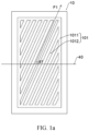
- An embodiment of the present disclosure provides an array substrate, as shown in FIG. 1a to FIG. 1c , including: a plurality of sub-pixel units, wherein the pixel units include a plurality of first sub-pixel units 10 displaying a first color, a plurality of second sub-pixel units 20 displaying a second color, and a plurality of third sub-pixel units 30 displaying a third color.
- the first color, the second color, and the third color are different, and a grayscale value of the first color and a grayscale value of the second color are greater than a grayscale value of the third color in a same display state.
- the array substrate includes a pair of short edges a parallel to a horizontal visual axis 40 and a pair of long edges b vertical to the horizontal visual axis 40.
- the first sub-pixel units 10 include a first pixel electrode 101.
- the first pixel electrode 101 includes at least two first branch electrodes 1012.
- the first branch electrodes 1012 extend along a first direction F1, and an acute angle between the first direction F1 and the horizontal visual axis 40 is a first angle ⁇ 1.
- the second sub-pixel units 20 include a second pixel electrode 201.
- the second pixel electrode 201 includes at least two second branch electrodes 2012.
- the second branch electrodes 2012 extend along a second direction F2, and an acute angle between the second direction F2 and the horizontal visual axis 40 is a second angle ⁇ 2.
- the third sub-pixel units 30 include a third pixel electrode 301.
- the third pixel electrode 301 includes at least two third branch electrodes 3012.
- the third branch electrodes 3012 extend along a third direction F3, and an acute angle between the third direction F2 and the horizontal visual axis 40 is a third angle ⁇ 3.
- the first angle ⁇ 1 is less than the third angle ⁇ 3, and the second angle ⁇ 2 is less than the third angle ⁇ 3.
- the array substrate of the present disclosure and a color filter substrate will be assembled to form a display panel which is a terminal product.
- the display panel may be a liquid crystal display (LCD) panel.
- the display panel may be a vertical alignment (VA) LCD panel.
- VA vertical alignment
- the assembled terminal product is the LCD panel which is taken as an example to describe the present embodiment.
- the LCD panel includes a color filter substrate CF and a thin-film transistor (TFT) array substrate AF arranged opposite to each other, and a liquid crystal layer LC arranged between the TFT substrate and the color filter substrate CF.
- the color filter substrate CF includes a red color resist, a green color resist, and a blue color resist.
- the array substrate AF includes a plurality of sub-pixel units, and one of the sub-pixel units corresponds to one of the color resists disposed on a color filter substrate CF.
- the first color, the second color, and the third color include, but are not limited to, any combinations of red (R), green (G), and blue (B).
- a grayscale value of the first color and a grayscale value of the second color are greater than a grayscale value of the third color.
- the first color is red
- the second color is green
- the third color is blue. That is, the first sub-pixel unit 10 corresponds to a red color resist, the second sub-pixel unit 20 corresponds to a green color resist, and the third sub-pixel unit 30 corresponds to the blue color resist.
- the first pixel electrode 101 of the first sub-pixel units 10, the second pixel electrode 201 of the second sub-pixel units 20, and the third sub-pixel unit 30 of the third pixel electrode 301 may have a single-domain structure, a double-domain structure, or a multi-domain structure, and are not limited in the present embodiment.
- the first sub-pixel units 10 include a main stem electrode, which is a shield electrode in a single-domain structure, and at least two first branch electrodes 1012 connected to the main stem electrode, extension directions of the two first branch electrodes 1012 are same and both extend along the first direction F1.
- the acute angle between the first direction F1 and the horizontal visual axis 40 is the first angle ⁇ 1.
- the second sub-pixel units 20 include a main stem electrode, which is a shield electrode in a single-domain structure, and at least two second branch electrodes 2012 connected to the main stem electrode, extension directions of the two second branch electrodes 2012 are same and both extend along the second direction F2.
- the acute angle between the second direction F2 and the horizontal visual axis 40 is the second angle ⁇ 2.
- the third sub-pixel units 10 include a main stem electrode, which is a shield electrode in a single-domain structure, and at least two third branch electrodes 3012 connected to the main stem electrode, extension directions of the two third branch electrodes 3012 are same and both extend along the third direction F3.
- the acute angle between the third direction F3 and the horizontal visual axis 40 is the third angle ⁇ 3.
- the skin tones are mixed color
- the skin tones are composed of sub-pixels having three colors R, G, and B.
- the sub-pixels having three colors of R, G, and B have different grayscale values and display different skin tones.
- the three sub-pixels in different grayscales need different degrees of improvement.
- a sub-pixel unit that displays blue is a low-grayscale sub-pixel unit.
- the low-grayscale sub-pixel unit that displays blue has worse viewing angle characteristics in VA LCD panel. That is, a color of an image displayed by the display panel viewed from a front side and a color of the image displayed by the display panel viewed from a lateral side are very different).
- the array substrate of the present disclosure is rectangular.
- the array substrate includes a pair of short edges a and a pair of long edges b.
- the long edges b are horizontal, and the short edges a are vertical, as shown in FIG. 2 .
- the long edges b are changed to be vertical and the short edges a are changed to be horizontal, and the display panel is in a portrait mode, as shown in Figure 2 .
- the display panel is changed from the landscape mode to the portrait mode.
- a visible length of the display panel viewed at vertical viewing angles is changed (the original short edges a becomes the long edge b), and a color shading issue will happen under vertical viewing angles.
- a structure of the sub-pixel units of the array substrate corresponding to the display panel is adjusted, and an angle between a branch electrode of a pixel electrode of the sub-pixel units and the horizontal visual axis 40 is adjusted, so that the color shift issue of the display panel viewed at vertical viewing angles is improved.
- the horizontal viewing axis 40 is parallel to the short edges a of the display panel and is perpendicular to the long edges b.
- the first angle ⁇ 1 is less than the third angle ⁇ 3, and the second angle ⁇ 2 is less than the third angle ⁇ 3, so that an angle between a branch electrode of the sub-pixel units having a low grayscale value and the horizontal visual axis 40 can be adjusted individually. Therefore, the angle between the branch electrode of the sub-pixel units having a low grayscale value and the horizontal visual axis 40 can be differentiated from angles between branch electrodes of the sub-pixel units having other grayscale value and the horizontal visual axis 40, thereby achieving a great improvement effect of a grayscale when three types of the sub-pixel units emit light.
- the array substrate includes three types of sub-pixel units displaying different colors.
- a grayscale value displayed by the first sub-pixel unit 10 a grayscale value displayed by the second sub-pixel unit 20, and a grayscale value displayed by the third sub-pixel unit 30 are different.
- An acute angle between a first electrode P1 of the first sub-pixel units and the horizontal visual axis 40 is the first angle ⁇ 1.
- An acute angle between a second electrode P2 of the second sub-pixel units and the horizontal visual axis 40 is the second angle ⁇ 2.
- An acute angle between a third electrode P3 of the third sub-pixel units and the horizontal visual axis 40 is the third angle ⁇ 3.
- the first angle ⁇ 1 is controlled to be less than the third angle ⁇ 3, the second angle ⁇ 2 is controlled to be less than the third angle ⁇ 3, and extensions direction of electrodes of the three sub-pixel units are respectively adjusted.
- the first angle ⁇ 1 and/or the second angle ⁇ 2 is greater than or equal to 45°
- the third angle ⁇ 3 is greater than 45°. Therefore, a plurality of branch electrodes of the sub-pixel units having poor viewing angles can be targetedly adjusted as much as possible, thereby achieving a great improvement effect of luminescence of the sub-pixel units having three different display colors as well as achieving a great optimization degree of vertical viewing angles of the sub-pixel units. As such, a color shading degree can be adjusted, and a color shading issue of display panels viewed at vertical viewing angles can be solved.
- first angle ⁇ 1 and/or the second angle ⁇ 2 are/is greater than or are/is equal to 45°, and the third angle ⁇ 3 is greater than 45°.
- an acute angle between branch electrodes and the horizontal viewing axis 40 is 45°, an image displayed by the display panel is even no matter the image is viewed from a lateral side or a right front side. (even if a color shading issue occurs, a color shading degree of the display panel viewed from the lateral side and a color shading degree of the display panel viewed from the right front side are same as long as lateral viewing angles are equal.).
- the acute angle is greater than 45°, an arrangement direction of the branch electrodes of the pixel electrodes in the sub-pixel units is closer to a vertical viewing angle of the display panel (compared to a horizontal viewing angle).
- first angle ⁇ 1 and/or the second angle ⁇ 2 are/is controlled to be greater than or equal to 45°
- the third angle ⁇ 3 is controlled to be greater than 45°. Therefore, an image displayed by the display panel viewed from a lateral side and having relatively a low color shading degree can be closer to the image displayed by the display panel viewed from a right front side. As such, a color shading issue of the display panel viewed at vertical viewing angles can be solved to a certain extent.
- a color shading degree of the third sub-pixel unit 30 is targetedly adjusted with respect to a color shading degree of the first sub-pixel units 10 and a color shading degree of the second sub-pixel unit 20. Therefore, vertical viewing angles of the sub-pixel units can be optimized as much as possible.
- first angle ⁇ 1 and/or the second angle ⁇ 2 are/is less than or equal to 60°, and the third angle ⁇ 3 is less than or equal to 65°.
- an acute angle between branch electrodes and the horizontal viewing axis 40 is 45°, an image displayed by the display panel is even no matter the image is viewed from a lateral side or a right front side. (even if a color shading issue occurs, a color shading degree of the display panel viewed from the lateral side and a color shading degree of the display panel viewed from the right front side are same as long as lateral viewing angles are equal.).
- the first angle ⁇ 1 and/or the second angle ⁇ 2 are/is less than or equal to 60°, arrangements of branch electrodes of the array substrate are much closer to closer to a vertical viewing angle of the display panel, and the display panel can still be used normally when the display panel is viewed at horizontal viewing angles.
- the acute angle between the branch electrodes and the horizontal viewing axis 40 is far away from 45°, transmittance of the sub-pixels will be reduced, affecting a display effect of the display panel.
- a difference between the first angle ⁇ 1 and the third angle ⁇ 3 is greater than 0.1° and is less than or equal to 20°, and a difference between the second angle ⁇ 2 and the third angle ⁇ 3 is greater than 0.1° and is less than or equal to 20°.
- first angle ⁇ 1 and/or the second angle ⁇ 2 less than or equal to 60° and making the third angle ⁇ 3 less than or equal to 65°, a color shading issue of the display panel viewed at vertical viewing angles can be solved without affecting transmittance of the display panel. As such, a display effect of the display panel can be prevented from being reduced.
- a difference between the first angle ⁇ 1 and the third angle ⁇ 3 is greater than 0.1° and is less than or equal to 10°; and/or a difference between the second angle ⁇ 2 and the third angle ⁇ 3 is greater than 0.1° and is less than or equal to 10°.
- differences between the first angle ⁇ 1, the second angle ⁇ 2, and the three angle ⁇ 3 are further controlled to be within a range of 0.1° to 10° (endpoints are included).
- a difference between the first angle ⁇ 1 and the third angle ⁇ 1 is 5°
- a difference between the second angle ⁇ 2 and the third angle ⁇ 3 is 5°
- the difference is 5°.
- Experimental comparison data of color shading adjustment effects of the preferred embodiment and a conventional technology are as shown below.
- the first angle ⁇ 1 is equal to the second angle ⁇ 2.
- first angle ⁇ 1 and the second angle ⁇ 2 can be greater than or equal to 45°, or can be less than or equal to 60°.
- the first pixel units 101 include a criss-cross-shaped first main stem electrode 1011.
- the first branch electrode 1012 are connected to the first main stem electrode 1011.
- Each of the first sub-pixel units 10 is divided into four pixel domains by the first main stem electrode 1011.
- the first branch electrodes 1012 are separatedly disposed in the four pixel domains.
- the first branch electrodes 1012 disposed in the four pixel domains extend from an intersection center of the first main stem electrode 1011 in four different directions.
- Four acute angles between extension directions of the first branch electrodes 1012 disposed in the four pixel domains and the horizontal visual axis 40 constitute a set of the first angles;
- the second pixel units 201 include a criss-cross-shaped second main stem electrode 1011.
- the second branch electrode 2012 are connected to the second main stem electrode 2011.
- Each of the second sub-pixel units 20 is divided into four pixel domains by the second main stem electrode 2011.
- the second branch electrodes 2012 are separatedly disposed in the four pixel domains.
- the second branch electrodes 2012 disposed in the four pixel domains extend from an intersection center of the second main stem electrode 2011 in four different directions.
- Four acute angles between extension directions of the second branch electrodes 2012 disposed in the four pixel domains and the horizontal visual axis 40 constitute a set of the second angles.
- the third pixel units 301 include a criss-cross-shaped third main stem electrode 3011.
- the third branch electrode 3012 are connected to the third main stem electrode 3011.
- Each of the third sub-pixel units 30 is divided into four pixel domains by the third main stem electrode 3011.
- the third branch electrodes 3012 are separatedly disposed in the four pixel domains.
- the third branch electrodes 3012 disposed in the four pixel domains extend from an intersection center of the third main stem electrode 3011 in four different directions.
- Four acute angles between extension directions of the third branch electrodes 3012 disposed in the four pixel domains and the horizontal visual axis 40 constitute a set of the third angles.
- any one of the third angles ⁇ 3 in the set of the third angles ⁇ 3 is greater than any one of the first angles ⁇ 1 in the set of the first angles ⁇ 1.
- Any one of the third angles ⁇ 3 in the set of the third angles ⁇ 3 is greater than any one of the second angles ⁇ 2 in the set of the second angles ⁇ 2.
- the sub-pixel units of the present embodiments all have a four-domain structure.
- the first main stem electrode 1011, the second main stem electrode 2011, and the third main stem electrode 3011 are criss-cross-shaped.
- the first main stem electrode 1011 is disposed on a center of the first sub-pixel units 10, thereby dividing the first sub-pixel units 10 into four domains with an equal area.
- the second main stem electrode 2011 disposed in the second sub-pixel units 20 and the third main stem electrode 3011 disposed in the third sub-pixel units 30 and the first main stem electrode 1011 have a same arrangement.
- the first branch electrodes 1012 disposed in the four pixel domains have different extension directions (including four first sub-directions).
- a first direction F1 includes any one of the four first sub-directions.
- the second sub-pixel units 20, the third sub-pixel units 30, and the first sub-pixel units have a same structure. That is, a second direction F2 includes any one of four second sub-directions (the second branch electrodes 2012 disposed in the four pixel domains have different extension directions).
- a third direction F3 includes any one of four third sub-directions (the third branch electrodes 3012 disposed in the four pixel domains have different extension directions).
- electrodes as shown in FIG. 4b and FIG. 4c and electrodes as shown in FIG. 4a have a similar arrangement.
- a main difference therebetween is that an inclined angle between branch electrodes disposed in each of domain areas and the horizontal visual axis 40 as shown in FIG. 4c and an inclined angle between branch electrodes disposed in each domain areas and the horizontal visual axis 40 as shown in FIG. 4a and FIG. 4b is different.
- the first stem electrode 1011 divides the first sub-pixel units 10 into four pixel domains, which are sequentially a first pixel domain A1, a second pixel domain A2, a third pixel domain A3, and a fourth pixel domain A4 in a counterclockwise order.
- the first branch electrodes 1012 in the four pixel domains are sequentially a first electrode P1, a second electrode P2, a third electrode P3, and a fourth electrode P4 in a counterclockwise order.
- the four electrodes respectively extend in four directions from an intersection of the first main stem electrode 1011.
- the horizontal visual axis 40 is an X axis and a right extension direction of the horizontal visual axis 40 is a positive direction.
- An angle a between the first electrode P1 and the horizontal visual axis 40 ranges from 45° to 60° (an acute angle between the first electrode P1 and the horizontal visual axis 40 ranges from 45° to 60°).
- the angle may be any one of 45°, 46°, 47°, 48°, 49°, 50°, 51°, 52°, 53°, 54°, 55°, 56°, 57°, 58°, 59°, or 60°.
- An angle b between the second electrode P2 and the horizontal visual axis 40 ranges from 135° to 120° (an acute angle between the second electrode P2 and the horizontal visual axis 40 ranges from 45° to 60°).
- the angle may be any one of 135°, 134°, 133°, 132°, 131°, 130°, 129°, 128°, 127°, 126°, 125°, 124°, 123°, 122°, 121°, or 120°.
- An angle c between the third electrode P3 and the horizontal visual axis 40 ranges from 225° to 240° (an acute angle between the third electrode P3 and the horizontal visual axis 40 ranges from 45° to 60°).
- the angle may be any one of 225°, 226°, 227°. 228°, 229°, 230°, 231°, 232°, 233°, 234°, 235°, 236°, 237°, 238°, 239°, or 240°.
- An angle d between the fourth electrode P4 and the horizontal visual axis 40 ranges from 315° to 300° (an acute angle between the fourth electrode P4 and the horizontal visual axis 40 ranges from 45° to 60°).
- the angle may be any one of 315°, 314°, 313°, 312°, 311°, 310°, 309°, 308°, 307°, 306°, 305°, 304°, 303°, 302°, 301°, or 300°.
- the second sub-pixel units 20 and the first sub-pixel units 10 have a same structure, and angles (a21, a22, a23, a24) are equal, which are not described here again.
- the first angle ⁇ 1 of the first branch electrodes 1012 of the first sub-pixel units 10 is 5° greater than the second angle ⁇ 2 of the second branch electrodes 2012 of the second pixel units 20.
- the third stem electrode 3011 divides the first sub-pixel units 30 into four pixel domains, which are sequentially a first pixel domain A1, a second pixel domain A2, a third pixel domain A3, and a fourth pixel domain A4 in a counterclockwise order.
- the third branch electrodes 3012 in the four pixel domains are sequentially a first electrode P1, a second electrode P2, a third electrode P3, and a fourth electrode P4 in a counterclockwise order.
- the four electrodes respectively extend in four directions from an intersection of the first main stem electrode 1011.
- the horizontal visual axis 40 is an X axis and a right extension direction of the horizontal visual axis 40 is a positive direction.
- An angle e between the first electrode P1 and the horizontal visual axis 40 ranges from 50° to 65° (an acute angle between the first electrode P1 and the horizontal visual axis 40 ranges from 55° to 65°).
- the angle may be any one of 50°, 51°, 52°, 53°, 54°, 55°, 56°, 57°, 58°, 59°, 60°, 61°, 62°, 63°, 64°, or 65°.
- An angle f between the second electrode P2 and the horizontal visual axis 40 ranges from 135° to 115° (an acute angle between the second electrode P2 and the horizontal visual axis 40 ranges from 55° to 65°).
- the angle may be any one of 130°, 129°, 128°, 127°, 126°, 125°, 124°, 123°, 122°, 121°, 120°, 119°, 118°, 117°, 116°, or 115°.
- An angle g between the third electrode P3 and the horizontal visual axis 40 ranges from 230° to 245° (an acute angle between the third electrode P3 and the horizontal visual axis 40 ranges from 55° to 65°).
- the angle may be any one of 230°, 231°, 232°. 233°, 234°, 235°, 236°, 237°, 238°, 239°, 240°, 241°, 242°, 243°, 244°, or 245°.
- An angle h between the fourth electrode P4 and the horizontal visual axis 40 ranges from 310° to 290° (an acute angle between the fourth electrode P4 and the horizontal visual axis 40 ranges from 55° to 65°).
- the angle may be any one of 310°, 309°, 308°, 307°, 306°, 305°, 304°, 303°, 302°, 301°, 300°, 299°, 298°, 297°, 296°, or 295°.
- the set of the first angles may include 45°, 46°, 45°, and 46°
- the set of the second angles may include 45°, 46°, 45°, and 46°
- the set of the third angles may include 50°, 61°, 50°, and 61°.
- any one of the third angles ⁇ 3 in the set of the third angles ⁇ 3 is greater than any one of the first angles ⁇ 1 in the set of the first angles ⁇ 1.
- Any one of the third angles ⁇ 3 in the set of the third angles ⁇ 3 is greater than any one of the second angles ⁇ 2 in the set of the second angles ⁇ 2.
- a color shading issue of the display panel viewed at vertical viewing angles can be solved. Therefore, in the array substrate, a light-shading area of an opaque part and a via hole of a thin-film transistor can be balanced. Aperture ratios of different domains of the pixel units can be equal. As such, a color shading issue can be solved to a certain extent no matter what angles the display panel is viewed at.
- the third angles ⁇ 3 in the set of the third angles are a same, the second angles ⁇ 2 in the set of the second angles are a same, and the first angles ⁇ 1 in the set of the first angles are a same.
- angles in a set of the angles are a same (as shown in FIG. 4a , FIG. 4b , and FIG. 4c , branch electrodes of four domains of the first sub-pixel units 10, the second sub-pixel units 20, and the third sub-pixel units 30 are symmetrically arranged with respect to an intersection point of the first stem electrode corresponding to the branch electrodes). That is, the set of the first angles includes 45°, 45°, 45°, and 45°, the set of the second angles includes 45°, 45°, 45°, and 45°, and the set of the third angles includes 50°, 50°, 50°, and 50°.
- branch electrodes disposed in the four pixel domains in a same pixel unit can be symmetrically arranged, which improves a display effect of the display panel
- an embodiment of the present disclosure further provides a mobile terminal.
- the mobile terminal includes any one of the array substrates mentioned in the above embodiments and a main terminal body.
- the main terminal body and the array substrate are integrated.
- C is a color saturation, and a is a red-green chromaticity.
- a value a being changed from positive to negative means that a color is changed from red (positive) to green (negative).
- b is a yellow-blue color chromaticity.
- a value b being changed from positive to negative means that a color is changed from yellow (positive) to blue (negative).
- a display having a sub-pixel unit having a four-domain structure is taken as a test sample.
- Original data are obtained by calculating a ratio of a color saturation viewed from the lateral side to a color saturation viewed from the right front side.
- Comparative example a conventional method of solving a color shading issue. Specifically, acute angles between pixel electrodes of three types of R, G, B sub-pixel units and the horizontal visual axis 40 are 50°.
- Blank example a conventional design. Specifically, acute angles between pixel electrodes of three types of R, G, B sub-pixel units and the horizontal visual axis 40 are 45°.
- Embodiment one technical solution of the present disclosure. Specifically, acute angles between pixel electrodes of R and G sub-pixel units and the horizontal visual axis 40 are 50°, and acute angles between pixel electrodes of B sub-pixel units and the horizontal visual axis 40 is 55°.
- Table 2 Skin2 observed angle Dc Dc improvement degree blank example comparative example embodiment blank example comparative example embodiment -60 0.6785 0.7032 0.7902 0.0000 0.0247 0.1117 -45 0.7074 0.7399 0.8226 0.0000 0.0325 0.1152 0 1.0000 1.0000 1.0000 0.0000 0.0000 0.0000 0.0000 45 0.7074 0.7399 0.8226 0.0000 0.0325 0.1152 60 0.6785 0.7032 0.7902 0.0000 0.0247 0.1117 Table 3.
- the embodiment of the present disclosure when a display color is skin2, compared to methods of simultaneously adjusting electrodes of R, G, and B sub-pixels, the embodiment of the present disclosure has a greater color shading improvement degree.
- the color shading improvement degree of the disclosure is 3 to 5 times a color shading improvement degree of the comparative example.
- the embodiment of the present disclosure when a display color is skin4, compared to methods of simultaneously adjusting electrodes of R, G, and B sub-pixels, the embodiment of the present disclosure has a greater color shading improvement degree.
- the color shading improvement degree of the disclosure is 3 to 4 times a color shading improvement degree of the comparative example.
- the embodiment of the present disclosure when a display color is skin5, compared to methods of simultaneously adjusting electrodes of R, G, and B sub-pixels, the embodiment of the present disclosure has a greater color shading improvement degree.
- the color shading improvement degree of the disclosure is 4 to 7 times a color shading improvement degree of the comparative example.
- the embodiment of the present disclosure has a greater color shading improvement degree.
- the color shading improvement degree of the disclosure is 2 to 4 times a color shading improvement degree of the comparative example.
- the array substrate provided by the present disclosure includes the sub-pixel units having three different display colors.
- a grayscale value of the first sub-pixel unit 10 In a same display state, a grayscale value of the first sub-pixel unit 10, a grayscale value of the second sub-pixel unit 20, and a grayscale value of the third sub-pixel units 30 are different.
- An acute angle between the first electrode P1 of the first sub-pixel unit and a horizontal visual axis is a first angle ⁇ 1
- an acute angle between the second electrode P2 of the second sub-pixel unit and the horizontal visual axis is the second angle ⁇ 2
- an acute angle between the third electrode P3 of the third sub-pixel unit and the horizontal visual axis is the third angle ⁇ 3.
- the first angle ⁇ 1 is controlled to be less than the third angle ⁇ 3
- the second angle ⁇ 2 is controlled to be less than the third angle ⁇ 3
- extension directions of electrodes of the three sub-pixel units are respectively adjusted. Therefore, a plurality of branch electrodes of the sub-pixel units having poor viewing angles can be targetedly adjusted as much as possible, thereby achieving a great improvement effect of luminescence of the sub-pixel units having three different display colors as well as optimizing vertical viewing angles of the sub-pixel units as much as possible. As such, a color shading degree can be adjusted, and a color shading issue of display panels viewed at vertical viewing angles can be solved.
Landscapes
- Physics & Mathematics (AREA)
- Nonlinear Science (AREA)
- Optics & Photonics (AREA)
- Crystallography & Structural Chemistry (AREA)
- Chemical & Material Sciences (AREA)
- General Physics & Mathematics (AREA)
- Mathematical Physics (AREA)
- Geometry (AREA)
- Spectroscopy & Molecular Physics (AREA)
- Engineering & Computer Science (AREA)
- Signal Processing (AREA)
- Liquid Crystal (AREA)
- Devices For Indicating Variable Information By Combining Individual Elements (AREA)
Abstract
Description
- The present disclosure relates to a field of display technologies, and more particularly, to an array substrate and a mobile terminal.
- Nowadays, flat display devices, such as liquid crystal displays, dominate a flat display device market because they have characteristics such as small size, light weight, small thickness, low power consumption, and no radiation.
- As usage scenarios become more and more diverse, liquid crystal display (LCD) panels include different display methods according to users' demands. When display panels are changed from a landscape mode to a portrait mode, a color shading issue may occur on the display panels because viewing angles are changed (from horizontal viewing angles to vertical viewing angles), resulting in a bad display effect of the display panels. Consequently, users may make a complaint because their experiences are affected.
- Embodiments of the present disclosure provide an array substrate and a mobile terminal to solve a following issue: when display panels are changed from a landscape mode to a portrait mode, a color shading issue may occur on the display panels because viewing angles are changed (from horizontal viewing angles to vertical viewing angles).
- To solve the above issue, technical solutions provided by the present disclosure are described as follows.
- An embodiment of the present disclosure provides an array substrate, comprising:
- a plurality of sub-pixel units, wherein the pixel units comprise a plurality of first sub-pixel units displaying a first color, a plurality of second sub-pixel units displaying a second color, and a plurality of third sub-pixel units displaying a third color, the first color, the second color, and the third color are different, a grayscale value of the first color and a grayscale value of the second color both are greater than a grayscale value of the third color;
- the array substrate comprises a pair of short edges parallel to a horizontal visual axis and a pair of long edges vertical to the horizontal visual axis;
- the first sub-pixel units comprise a first pixel electrode, the first pixel electrode comprises at least two first branch electrodes, the first branch electrodes extend along a first direction, and an acute angle between the first direction and the horizontal visual axis is a first angle;
- the second sub-pixel units comprise a second pixel electrode, the second pixel electrode comprises at least two second branch electrodes, the second branch electrodes extend along a second direction, and an acute angle between the second direction and the horizontal visual axis is a second angle;
- the third sub-pixel units comprise a third pixel electrode, the third pixel electrode comprises at least two third branch electrodes, the third branch electrodes extend along a third direction, and an acute angle between the third direction and the horizontal visual axis is a third angle; and
- wherein the first angle is less than the third angle, and the second angle is less than the third angle.
- In one embodiment, the first angle and/or the second angle are/is greater than or equal to 45°, and the third angle is greater than 45°.
- In one embodiment, the first angle and/or the second angle are/is less than or equal to 60°, and the third angle is less than or equal to 65°.
- In one embodiment, a difference between the first angle and the third angle is greater than 0.1° and is less than or equal to 10°; and/or
a difference between the second angle and the third angle is greater than 0.1° and is less than or equal to 10°. - In one embodiment, the difference between the first angle and the third angle is 5°, and the difference between the second angle and the third angle is 5°.
- In one embodiment, the first angle is equal to the second angle.
- In one embodiment, the first pixel electrodes comprise a first main stem electrode, the first main stem electrode is criss-cross-shaped, the first branch electrodes are connected to the first main stem electrode, each of the first sub-pixel units is divided into four pixel domains by the first main stem electrode, the first branch electrodes are separately disposed in the four pixel domains, the first branch electrodes disposed in the four pixel domains extend from an intersection center of the first main stem electrode in four different directions, and four acute angles between extension directions of the first branch electrodes disposed in the four pixel domains and the horizontal visual axis constitute a set of first angles;
- the second pixel electrodes comprise a second main stem electrode, the second main stem electrode is criss-cross-shaped, the second branch electrodes are connected to the second main stem electrode, each of the second sub-pixel units is divided into four pixel domains by the second main stem electrode, the second branch electrodes are separately disposed in the four pixel domains, the second branch electrodes disposed in the four pixel domains extend from an intersection center of the second main stem electrode in four different directions, and four acute angles between extension directions of the second branch electrodes disposed in the four pixel domains and the horizontal visual axis constitute a set of second angles;
- the third pixel electrodes comprise a third main stem electrode, the third main stem electrode is criss-cross-shaped, the third branch electrodes are connected to the third main stem electrode, each of the third sub-pixel units is divided into four pixel domains by the third main stem electrode, the third branch electrodes are separately disposed in the four pixel domains, the third branch electrodes disposed in the four pixel domains extend from an intersection center of the third main stem electrode in four different directions, and four acute angles between extension directions of the third branch electrodes disposed in the four pixel domains and the horizontal visual axis constitute a set of third angles; and
- any one of the third angles in the set of the third angles is greater than any one of the first angles in the set of the first angles, and any one of the third angles in the set of the third angles is greater than any one of the second angles in the set of the second angles.
- In one embodiment, the third angles in the set of the third angles are equal, the second angles in the set of the second angles are equal, and the first angles in the set of the first angles are equal.
- In one embodiment, the third angles in the set of the third angles are 55°, the first angles in the set of the first angles and the second angles in the set of the second angles are 50°.
- In one embodiment, the first color and the second color comprise any one of red or green, and the third color comprises blue.
- The present disclosure further provides a mobile terminal, comprising an array substrate and a main terminal body, and the array substrate and the main terminal body are integrated;
wherein the array substrate comprises: - a plurality of sub-pixel units, wherein the pixel units comprise a plurality of first sub-pixel units displaying a first color, a plurality of second sub-pixel units displaying a second color, and a plurality of third sub-pixel units displaying a third color, the first color, the second color, and the third color are different, a grayscale value of the first color and a grayscale value of the second color both are greater than a grayscale value of the third color;
- the array substrate comprises a pair of short edges parallel to a horizontal visual axis and a pair of long edges vertical to the horizontal visual axis;
- the first sub-pixel units comprise a first pixel electrode, the first pixel electrode comprises at least two first branch electrodes, the first branch electrodes extend along a first direction, and an acute angle between the first direction and the horizontal visual axis is a first angle;
- the second sub-pixel units comprise a second pixel electrode, the second pixel electrode comprises at least two second branch electrodes, the second branch electrodes extend along a second direction, and an acute angle between the second direction and the horizontal visual axis is a second angle;
- the third sub-pixel units comprise a third pixel electrode, the third pixel electrode comprises at least two third branch electrodes, the third branch electrodes extend along a third direction, and an acute angle between the third direction and the horizontal visual axis is a third angle; and
- wherein the first angle is less than the third angle, and the second angle is less than the third angle.
- In one embodiment, the first angle and/or the second angle are/is greater than or equal to 45°, and the third angle is greater than 45°.
- In one embodiment, the first angle and/or the second angle are/is less than or equal to 60°, and the third angle is less than or equal to 65°.
- In one embodiment, a difference between the first angle and the third angle is greater than 0.1° and is less than or equal to 10°; and/or
a difference between the second angle and the third angle is greater than 0.1° and is less than or equal to 10°. - In one embodiment, the difference between the first angle and the third angle is 5°, and the difference between the second angle and the third angle is 5°.
- In one embodiment, the first angle is equal to the second angle.
- In one embodiment, the first pixel electrodes comprise a first main stem electrode, the first main stem electrode is criss-cross-shaped, the first branch electrodes are connected to the first main stem electrode, each of the first sub-pixel units is divided into four pixel domains by the first main stem electrode, the first branch electrodes are separately disposed in the four pixel domains, the first branch electrodes disposed in the four pixel domains extend from an intersection center of the first main stem electrode in four different directions, and four acute angles between extension directions of the first branch electrodes disposed in the four pixel domains and the horizontal visual axis constitute a set of first angles;
- the second pixel electrodes comprise a second main stem electrode, the second main stem electrode is criss-cross-shaped, the second branch electrodes are connected to the second main stem electrode, each of the second sub-pixel units is divided into four pixel domains by the second main stem electrode, the second branch electrodes are separately disposed in the four pixel domains, the second branch electrodes disposed in the four pixel domains extend from an intersection center of the second main stem electrode in four different directions, and four acute angles between extension directions of the second branch electrodes disposed in the four pixel domains and the horizontal visual axis constitute a set of second angles;
- the third pixel electrodes comprise a third main stem electrode, the third main stem electrode is criss-cross-shaped, the third branch electrodes are connected to the third main stem electrode, each of the third sub-pixel units is divided into four pixel domains by the third main stem electrode, the third branch electrodes are separately disposed in the four pixel domains, the third branch electrodes disposed in the four pixel domains extend from an intersection center of the third main stem electrode in four different directions, and four acute angles between extension directions of the third branch electrodes disposed in the four pixel domains and the horizontal visual axis constitute a set of third angles; and
- any one of the third angles in the set of the third angles is greater than any one of the first angles in the set of the first angles, and any one of the third angles in the set of the third angles is greater than any one of the second angles in the set of the second angles.
- In one embodiment, the third angles in the set of the third angles are equal, the second angles in the set of the second angles are equal, and the first angles in the set of the first angles are equal.
- In one embodiment, the third angles in the set of the third angles are 55°, the first angles in the set of the first angles and the second angles in the set of the second angles are 50°.
- In one embodiment, the first color and the second color comprise any one of red or green, and the third color comprises blue.
- Regarding the beneficial effects:
an array substrate provided by the present disclosure includes a plurality of sub-pixel units having three different display colors. In a same display state, a grayscale value of a first sub-pixel unit, a grayscale value of a second sub-pixel unit, and a grayscale value of a third sub-pixel units are different. An acute angle between a first electrode of the first sub-pixel unit and a horizontal visual axis is a first angle, an acute angle between a second electrode of the second sub-pixel unit and the horizontal visual axis is a second angle, and an acute angle between a third electrode of the third sub-pixel unit and the horizontal visual axis is a third angle. The first angle is controlled to be less than the third angle, the second angle is controlled to be less than the third angle, and extension directions of electrodes of the three sub-pixel units are respectively adjusted. Therefore, a plurality of branch electrodes of the sub-pixel units having poor viewing angles can be targetedly adjusted as much as possible, thereby achieving a great improvement effect of luminescence of the sub-pixel units having three different display colors as well as optimizing vertical viewing angles of the sub-pixel units as much as possible. As such, a color shading degree can be adjusted, and a color shading issue of display panels viewed at vertical viewing angles can be solved. -
-
FIG. 1a is a structural schematic view showing a single-domain first sub-pixel unit provided by an embodiment of the present disclosure. -
FIG. 1b is a structural schematic view showing a single-domain second sub-pixel unit provided by the embodiment of the present disclosure. -
FIG. 1c is a structural schematic view showing a single-domain third sub-pixel unit provided by the embodiment of the present disclosure. -
FIG. 2 is a schematic view showing a method of using a display panel assembled from an array substrate provided by an embodiment of the present disclosure. -
FIG. 3 is a structural schematic view showing the display panel assembled from the array substrate provided by the embodiment of the present disclosure. -
FIG. 4a is a structural schematic view showing a four-domain first sub-pixel unit provided by an embodiment of the present disclosure. -
FIG. 4b is a structural schematic view showing a four-domain second sub-pixel unit provided by an embodiment of the present disclosure. -
FIG. 4c is a structural schematic view showing a four-domain second sub-pixel unit provided by an embodiment of the present disclosure. - The present disclosure provides an array substrate and a mobile terminal. Embodiments are further described below in detail with reference to accompanying drawings to make objectives, technical solutions, and effects of the present disclosure clearer and more precise. It should be noted that described embodiments are merely used to construct the present disclosure and are not intended to limit the present disclosure.
- An embodiment of the present disclosure provides an array substrate, as shown in
FIG. 1a to FIG. 1c , including:
a plurality of sub-pixel units, wherein the pixel units include a plurality of firstsub-pixel units 10 displaying a first color, a plurality of secondsub-pixel units 20 displaying a second color, and a plurality of thirdsub-pixel units 30 displaying a third color. The first color, the second color, and the third color are different, and a grayscale value of the first color and a grayscale value of the second color are greater than a grayscale value of the third color in a same display state. - The array substrate includes a pair of short edges a parallel to a horizontal
visual axis 40 and a pair of long edges b vertical to the horizontalvisual axis 40. - The
first sub-pixel units 10 include a first pixel electrode 101. The first pixel electrode 101 includes at least two first branch electrodes 1012. The first branch electrodes 1012 extend along a first direction F1, and an acute angle between the first direction F1 and the horizontalvisual axis 40 is a first angle α1. - The
second sub-pixel units 20 include asecond pixel electrode 201. Thesecond pixel electrode 201 includes at least twosecond branch electrodes 2012. Thesecond branch electrodes 2012 extend along a second direction F2, and an acute angle between the second direction F2 and the horizontalvisual axis 40 is a second angle α2. - The third
sub-pixel units 30 include athird pixel electrode 301. Thethird pixel electrode 301 includes at least twothird branch electrodes 3012. Thethird branch electrodes 3012 extend along a third direction F3, and an acute angle between the third direction F2 and the horizontalvisual axis 40 is a third angle α3. - The first angle α1 is less than the third angle α3, and the second angle α2 is less than the third angle α3.
- It should be noted that the array substrate of the present disclosure and a color filter substrate will be assembled to form a display panel which is a terminal product. The display panel may be a liquid crystal display (LCD) panel. Specifically, the display panel may be a vertical alignment (VA) LCD panel. The assembled terminal product is the LCD panel which is taken as an example to describe the present embodiment.
- As shown in
FIG. 3 , the LCD panel includes a color filter substrate CF and a thin-film transistor (TFT) array substrate AF arranged opposite to each other, and a liquid crystal layer LC arranged between the TFT substrate and the color filter substrate CF. The color filter substrate CF includes a red color resist, a green color resist, and a blue color resist. - The array substrate AF includes a plurality of sub-pixel units, and one of the sub-pixel units corresponds to one of the color resists disposed on a color filter substrate CF.
- Specifically, the first color, the second color, and the third color include, but are not limited to, any combinations of red (R), green (G), and blue (B). In a same display state, a grayscale value of the first color and a grayscale value of the second color are greater than a grayscale value of the third color.
- In the present embodiment, the first color is red, the second color is green, and the third color is blue. That is, the
first sub-pixel unit 10 corresponds to a red color resist, thesecond sub-pixel unit 20 corresponds to a green color resist, and thethird sub-pixel unit 30 corresponds to the blue color resist. - It should be noted that, in the array substrate provided by the embodiment of the present disclosure, the first pixel electrode 101 of the
first sub-pixel units 10, thesecond pixel electrode 201 of thesecond sub-pixel units 20, and thethird sub-pixel unit 30 of thethird pixel electrode 301 may have a single-domain structure, a double-domain structure, or a multi-domain structure, and are not limited in the present embodiment. - For example, as shown in
FIG. 1a , thefirst sub-pixel units 10 include a main stem electrode, which is a shield electrode in a single-domain structure, and at least two first branch electrodes 1012 connected to the main stem electrode, extension directions of the two first branch electrodes 1012 are same and both extend along the first direction F1. The acute angle between the first direction F1 and the horizontalvisual axis 40 is the first angle α1. - For example, as shown in
FIG. 1b , thesecond sub-pixel units 20 include a main stem electrode, which is a shield electrode in a single-domain structure, and at least twosecond branch electrodes 2012 connected to the main stem electrode, extension directions of the twosecond branch electrodes 2012 are same and both extend along the second direction F2. The acute angle between the second direction F2 and the horizontalvisual axis 40 is the second angle α2. - For example, as shown in
FIG. 1c , the thirdsub-pixel units 10 include a main stem electrode, which is a shield electrode in a single-domain structure, and at least twothird branch electrodes 3012 connected to the main stem electrode, extension directions of the twothird branch electrodes 3012 are same and both extend along the third direction F3. The acute angle between the third direction F3 and the horizontalvisual axis 40 is the third angle α3. - Taking a display panel displaying different skin tones (the skin tones are mixed color) as an example, when an LCD panel displays, the skin tones are composed of sub-pixels having three colors R, G, and B. A difference therebetween is that the sub-pixels having three colors of R, G, and B have different grayscale values and display different skin tones. According to the above principle, when improving viewing angles, the three sub-pixels in different grayscales need different degrees of improvement. Commonly, among the three colors of the mixture color, a sub-pixel unit that displays blue is a low-grayscale sub-pixel unit. The low-grayscale sub-pixel unit that displays blue has worse viewing angle characteristics in VA LCD panel. That is, a color of an image displayed by the display panel viewed from a front side and a color of the image displayed by the display panel viewed from a lateral side are very different).
- Users may watch a display image displayed by display panels at different viewing angles. When the display panel is viewed from a right front side and a visual line is vertical to the display panel, a color shading issue will not happen. When the display panel is viewed from a lateral side instead of from the right front side, a color shading issue will happen. When lateral viewing angles range from 0° to 90° (endpoints are excluded), a greater the lateral viewing angles, a more serious a color shading issue occurring on the display panel.
- The array substrate of the present disclosure is rectangular. The array substrate includes a pair of short edges a and a pair of long edges b. Commonly, when the display panel is in a landscape mode, the long edges b are horizontal, and the short edges a are vertical, as shown in
FIG. 2 . However, in some usage scenarios, it is necessary to change a usage mode of the display panel. The long edges b are changed to be vertical and the short edges a are changed to be horizontal, and the display panel is in a portrait mode, as shown inFigure 2 . Although users' viewing angles do not change, the display panel is changed from the landscape mode to the portrait mode. Therefore, a visible length of the display panel viewed at vertical viewing angles is changed (the original short edges a becomes the long edge b), and a color shading issue will happen under vertical viewing angles. As such, in the present disclosure, a structure of the sub-pixel units of the array substrate corresponding to the display panel is adjusted, and an angle between a branch electrode of a pixel electrode of the sub-pixel units and the horizontalvisual axis 40 is adjusted, so that the color shift issue of the display panel viewed at vertical viewing angles is improved. - Specifically, the
horizontal viewing axis 40 is parallel to the short edges a of the display panel and is perpendicular to the long edges b. - Specifically, the first angle α1 is less than the third angle α3, and the second angle α2 is less than the third angle α3, so that an angle between a branch electrode of the sub-pixel units having a low grayscale value and the horizontal
visual axis 40 can be adjusted individually. Therefore, the angle between the branch electrode of the sub-pixel units having a low grayscale value and the horizontalvisual axis 40 can be differentiated from angles between branch electrodes of the sub-pixel units having other grayscale value and the horizontalvisual axis 40, thereby achieving a great improvement effect of a grayscale when three types of the sub-pixel units emit light. - It should be understood that the array substrate includes three types of sub-pixel units displaying different colors. In a same display state, a grayscale value displayed by the
first sub-pixel unit 10, a grayscale value displayed by thesecond sub-pixel unit 20, and a grayscale value displayed by thethird sub-pixel unit 30 are different. An acute angle between a first electrode P1 of the first sub-pixel units and the horizontalvisual axis 40 is the first angle α1. An acute angle between a second electrode P2 of the second sub-pixel units and the horizontalvisual axis 40 is the second angle α2. An acute angle between a third electrode P3 of the third sub-pixel units and the horizontalvisual axis 40 is the third angle α3. The first angle α1 is controlled to be less than the third angle α3, the second angle α2 is controlled to be less than the third angle α3, and extensions direction of electrodes of the three sub-pixel units are respectively adjusted. - In one embodiment, the first angle α1 and/or the second angle α2 is greater than or equal to 45°, and the third angle α3 is greater than 45°. Therefore, a plurality of branch electrodes of the sub-pixel units having poor viewing angles can be targetedly adjusted as much as possible, thereby achieving a great improvement effect of luminescence of the sub-pixel units having three different display colors as well as achieving a great optimization degree of vertical viewing angles of the sub-pixel units. As such, a color shading degree can be adjusted, and a color shading issue of display panels viewed at vertical viewing angles can be solved.
- In one embodiment, the first angle α1 and/or the second angle α2 are/is greater than or are/is equal to 45°, and the third angle α3 is greater than 45°.
- Specifically, when an acute angle between branch electrodes and the
horizontal viewing axis 40 is 45°, an image displayed by the display panel is even no matter the image is viewed from a lateral side or a right front side. (even if a color shading issue occurs, a color shading degree of the display panel viewed from the lateral side and a color shading degree of the display panel viewed from the right front side are same as long as lateral viewing angles are equal.). When the acute angle is greater than 45°, an arrangement direction of the branch electrodes of the pixel electrodes in the sub-pixel units is closer to a vertical viewing angle of the display panel (compared to a horizontal viewing angle). - It should be understood that the first angle α1 and/or the second angle α2 are/is controlled to be greater than or equal to 45°, and the third angle α3 is controlled to be greater than 45°. Therefore, an image displayed by the display panel viewed from a lateral side and having relatively a low color shading degree can be closer to the image displayed by the display panel viewed from a right front side. As such, a color shading issue of the display panel viewed at vertical viewing angles can be solved to a certain extent. Furthermore, because the third angle α3 is greater than the first angle α1 and the second angle α2, a color shading degree of the
third sub-pixel unit 30 is targetedly adjusted with respect to a color shading degree of thefirst sub-pixel units 10 and a color shading degree of thesecond sub-pixel unit 20. Therefore, vertical viewing angles of the sub-pixel units can be optimized as much as possible. - In an embodiment, the first angle α1 and/or the second angle α2 are/is less than or equal to 60°, and the third angle α3 is less than or equal to 65°.
- Specifically, when an acute angle between branch electrodes and the
horizontal viewing axis 40 is 45°, an image displayed by the display panel is even no matter the image is viewed from a lateral side or a right front side. (even if a color shading issue occurs, a color shading degree of the display panel viewed from the lateral side and a color shading degree of the display panel viewed from the right front side are same as long as lateral viewing angles are equal.). By making the first angle α1 and/or the second angle α2 are/is less than or equal to 60°, arrangements of branch electrodes of the array substrate are much closer to closer to a vertical viewing angle of the display panel, and the display panel can still be used normally when the display panel is viewed at horizontal viewing angles. Furthermore, if the acute angle between the branch electrodes and thehorizontal viewing axis 40 is far away from 45°, transmittance of the sub-pixels will be reduced, affecting a display effect of the display panel. - Specifically, according to the above ranges, a difference between the first angle α1 and the third angle α3 is greater than 0.1° and is less than or equal to 20°, and a difference between the second angle α2 and the third angle α3 is greater than 0.1° and is less than or equal to 20°.
- By making the first angle α1 and/or the second angle α2 less than or equal to 60° and making the third angle α3 less than or equal to 65°, a color shading issue of the display panel viewed at vertical viewing angles can be solved without affecting transmittance of the display panel. As such, a display effect of the display panel can be prevented from being reduced.
- In one embodiment, a difference between the first angle α1 and the third angle α3 is greater than 0.1° and is less than or equal to 10°; and/or
a difference between the second angle α2 and the third angle α3 is greater than 0.1° and is less than or equal to 10°. - Specifically, to prevent a color shading issue from occurring on a white image mixed from red light, green light, and blue light emitted by three types of the sub-pixels, differences between the first angle α1, the second angle α2, and the three angle α3 are further controlled to be within a range of 0.1° to 10° (endpoints are included).
- By controlling the difference between the first angle α1, the second angle α2, and the third angle α3 to be within the range of 0.1° to 10°, a color shading degree of the display panel assembled from the array substrate viewed at vertical viewing angles can be reduced
- In one embodiment, a difference between the first angle α1 and the third angle α1 is 5°, and a difference between the second angle α2 and the third angle α3 is 5°.
- Specifically, in a preferred embodiment, the difference is 5°. Experimental comparison data of color shading adjustment effects of the preferred embodiment and a conventional technology are as shown below.
- In one embodiment, the first angle α1 is equal to the second angle α2.
- Specifically, the first angle α1 and the second angle α2 can be greater than or equal to 45°, or can be less than or equal to 60°.
- It should be understood that because a grayscale value of a color displayed by the
first sub-pixel units 10 and a grayscale value of a color displayed by thesecond sub-pixel units 20 are not very different, making the first angle α1 equal to the second angle α2 can further simplifying manufacturing processes and reducing difficulty of manufacturing the array substrate. - In one embodiment, the first pixel units 101 include a criss-cross-shaped first
main stem electrode 1011. The first branch electrode 1012 are connected to the firstmain stem electrode 1011. Each of thefirst sub-pixel units 10 is divided into four pixel domains by the firstmain stem electrode 1011. The first branch electrodes 1012 are separatedly disposed in the four pixel domains. The first branch electrodes 1012 disposed in the four pixel domains extend from an intersection center of the firstmain stem electrode 1011 in four different directions. Four acute angles between extension directions of the first branch electrodes 1012 disposed in the four pixel domains and the horizontalvisual axis 40 constitute a set of the first angles; - The
second pixel units 201 include a criss-cross-shaped secondmain stem electrode 1011. Thesecond branch electrode 2012 are connected to the secondmain stem electrode 2011. Each of thesecond sub-pixel units 20 is divided into four pixel domains by the secondmain stem electrode 2011. Thesecond branch electrodes 2012 are separatedly disposed in the four pixel domains. Thesecond branch electrodes 2012 disposed in the four pixel domains extend from an intersection center of the secondmain stem electrode 2011 in four different directions. Four acute angles between extension directions of thesecond branch electrodes 2012 disposed in the four pixel domains and the horizontalvisual axis 40 constitute a set of the second angles. - The
third pixel units 301 include a criss-cross-shaped thirdmain stem electrode 3011. Thethird branch electrode 3012 are connected to the thirdmain stem electrode 3011. Each of the thirdsub-pixel units 30 is divided into four pixel domains by the thirdmain stem electrode 3011. Thethird branch electrodes 3012 are separatedly disposed in the four pixel domains. Thethird branch electrodes 3012 disposed in the four pixel domains extend from an intersection center of the thirdmain stem electrode 3011 in four different directions. Four acute angles between extension directions of thethird branch electrodes 3012 disposed in the four pixel domains and the horizontalvisual axis 40 constitute a set of the third angles. - Any one of the third angles α3 in the set of the third angles α3 is greater than any one of the first angles α1 in the set of the first angles α1. Any one of the third angles α3 in the set of the third angles α3 is greater than any one of the second angles α2 in the set of the second angles α2. Specifically, as shown in
FIG. 4a ,FIG. 4b , andFIG. 4c , the sub-pixel units of the present embodiments all have a four-domain structure. The firstmain stem electrode 1011, the secondmain stem electrode 2011, and the thirdmain stem electrode 3011 are criss-cross-shaped. The firstmain stem electrode 1011 is disposed on a center of thefirst sub-pixel units 10, thereby dividing thefirst sub-pixel units 10 into four domains with an equal area. The secondmain stem electrode 2011 disposed in thesecond sub-pixel units 20 and the thirdmain stem electrode 3011 disposed in the thirdsub-pixel units 30 and the firstmain stem electrode 1011 have a same arrangement. - Specifically, in the first sub-pixel units, the first branch electrodes 1012 disposed in the four pixel domains have different extension directions (including four first sub-directions). A first direction F1 includes any one of the four first sub-directions. The
second sub-pixel units 20, the thirdsub-pixel units 30, and the first sub-pixel units have a same structure. That is, a second direction F2 includes any one of four second sub-directions (thesecond branch electrodes 2012 disposed in the four pixel domains have different extension directions). A third direction F3 includes any one of four third sub-directions (thethird branch electrodes 3012 disposed in the four pixel domains have different extension directions). - In one specific embodiment, as shown in
FIG. 4a ,FIG. 4b , andFIG. 4c , electrodes as shown inFIG. 4b andFIG. 4c and electrodes as shown inFIG. 4a have a similar arrangement. A main difference therebetween is that an inclined angle between branch electrodes disposed in each of domain areas and the horizontalvisual axis 40 as shown inFIG. 4c and an inclined angle between branch electrodes disposed in each domain areas and the horizontalvisual axis 40 as shown inFIG. 4a andFIG. 4b is different. - For example, in
FIG. 4a , thefirst stem electrode 1011 divides thefirst sub-pixel units 10 into four pixel domains, which are sequentially a first pixel domain A1, a second pixel domain A2, a third pixel domain A3, and a fourth pixel domain A4 in a counterclockwise order. The first branch electrodes 1012 in the four pixel domains are sequentially a first electrode P1, a second electrode P2, a third electrode P3, and a fourth electrode P4 in a counterclockwise order. The four electrodes respectively extend in four directions from an intersection of the firstmain stem electrode 1011. The horizontalvisual axis 40 is an X axis and a right extension direction of the horizontalvisual axis 40 is a positive direction. An angle a between the first electrode P1 and the horizontalvisual axis 40 ranges from 45° to 60° (an acute angle between the first electrode P1 and the horizontalvisual axis 40 ranges from 45° to 60°). Specifically, the angle may be any one of 45°, 46°, 47°, 48°, 49°, 50°, 51°, 52°, 53°, 54°, 55°, 56°, 57°, 58°, 59°, or 60°. - An angle b between the second electrode P2 and the horizontal
visual axis 40 ranges from 135° to 120° (an acute angle between the second electrode P2 and the horizontalvisual axis 40 ranges from 45° to 60°). Specifically, the angle may be any one of 135°, 134°, 133°, 132°, 131°, 130°, 129°, 128°, 127°, 126°, 125°, 124°, 123°, 122°, 121°, or 120°. - An angle c between the third electrode P3 and the horizontal
visual axis 40 ranges from 225° to 240° (an acute angle between the third electrode P3 and the horizontalvisual axis 40 ranges from 45° to 60°). Specifically, the angle may be any one of 225°, 226°, 227°. 228°, 229°, 230°, 231°, 232°, 233°, 234°, 235°, 236°, 237°, 238°, 239°, or 240°. - An angle d between the fourth electrode P4 and the horizontal
visual axis 40 ranges from 315° to 300° (an acute angle between the fourth electrode P4 and the horizontalvisual axis 40 ranges from 45° to 60°). Specifically, the angle may be any one of 315°, 314°, 313°, 312°, 311°, 310°, 309°, 308°, 307°, 306°, 305°, 304°, 303°, 302°, 301°, or 300°. - In
FIG. 4b , thesecond sub-pixel units 20 and thefirst sub-pixel units 10 have a same structure, and angles (a21, a22, a23, a24) are equal, which are not described here again. - In
FIG. 4c , compared to the third angle α3 of thethird branch electrodes 3012 of the thirdsub-pixel units 30, the first angle α1 of the first branch electrodes 1012 of thefirst sub-pixel units 10 is 5° greater than the second angle α2 of thesecond branch electrodes 2012 of thesecond pixel units 20. - In the third
sub-pixel units 30, thethird stem electrode 3011 divides thefirst sub-pixel units 30 into four pixel domains, which are sequentially a first pixel domain A1, a second pixel domain A2, a third pixel domain A3, and a fourth pixel domain A4 in a counterclockwise order. Thethird branch electrodes 3012 in the four pixel domains are sequentially a first electrode P1, a second electrode P2, a third electrode P3, and a fourth electrode P4 in a counterclockwise order. The four electrodes respectively extend in four directions from an intersection of the firstmain stem electrode 1011. The horizontalvisual axis 40 is an X axis and a right extension direction of the horizontalvisual axis 40 is a positive direction. An angle e between the first electrode P1 and the horizontalvisual axis 40 ranges from 50° to 65° (an acute angle between the first electrode P1 and the horizontalvisual axis 40 ranges from 55° to 65°). Specifically, the angle may be any one of 50°, 51°, 52°, 53°, 54°, 55°, 56°, 57°, 58°, 59°, 60°, 61°, 62°, 63°, 64°, or 65°. - An angle f between the second electrode P2 and the horizontal
visual axis 40 ranges from 135° to 115° (an acute angle between the second electrode P2 and the horizontalvisual axis 40 ranges from 55° to 65°). Specifically, the angle may be any one of 130°, 129°, 128°, 127°, 126°, 125°, 124°, 123°, 122°, 121°, 120°, 119°, 118°, 117°, 116°, or 115°. - An angle g between the third electrode P3 and the horizontal
visual axis 40 ranges from 230° to 245° (an acute angle between the third electrode P3 and the horizontalvisual axis 40 ranges from 55° to 65°). Specifically, the angle may be any one of 230°, 231°, 232°. 233°, 234°, 235°, 236°, 237°, 238°, 239°, 240°, 241°, 242°, 243°, 244°, or 245°. - An angle h between the fourth electrode P4 and the horizontal
visual axis 40 ranges from 310° to 290° (an acute angle between the fourth electrode P4 and the horizontalvisual axis 40 ranges from 55° to 65°). Specifically, the angle may be any one of 310°, 309°, 308°, 307°, 306°, 305°, 304°, 303°, 302°, 301°, 300°, 299°, 298°, 297°, 296°, or 295°. - Specifically, in the above ranges, the set of the first angles may include 45°, 46°, 45°, and 46°, and the set of the second angles may include 45°, 46°, 45°, and 46°, and the set of the third angles may include 50°, 61°, 50°, and 61°.
- Specifically, any one of the third angles α3 in the set of the third angles α3 is greater than any one of the first angles α1 in the set of the first angles α1. Any one of the third angles α3 in the set of the third angles α3 is greater than any one of the second angles α2 in the set of the second angles α2.
- By disposing the four-domain structure, a color shading issue of the display panel viewed at vertical viewing angles can be solved. Therefore, in the array substrate, a light-shading area of an opaque part and a via hole of a thin-film transistor can be balanced. Aperture ratios of different domains of the pixel units can be equal. As such, a color shading issue can be solved to a certain extent no matter what angles the display panel is viewed at.
- In one embodiment, the third angles α3 in the set of the third angles are a same, the second angles α2 in the set of the second angles are a same, and the first angles α1 in the set of the first angles are a same.
- Specifically, angles in a set of the angles are a same (as shown in
FIG. 4a ,FIG. 4b , andFIG. 4c , branch electrodes of four domains of thefirst sub-pixel units 10, thesecond sub-pixel units 20, and the thirdsub-pixel units 30 are symmetrically arranged with respect to an intersection point of the first stem electrode corresponding to the branch electrodes). That is, the set of the first angles includes 45°, 45°, 45°, and 45°, the set of the second angles includes 45°, 45°, 45°, and 45°, and the set of the third angles includes 50°, 50°, 50°, and 50°. - By making the third angles α3 in the set of the third angles equal, making the second angles α2 in the set of the second angles equal, and making the first angles α1 in the set of the first angles equal, branch electrodes disposed in the four pixel domains in a same pixel unit can be symmetrically arranged, which improves a display effect of the display panel
- In addition, an embodiment of the present disclosure further provides a mobile terminal. The mobile terminal includes any one of the array substrates mentioned in the above embodiments and a main terminal body. The main terminal body and the array substrate are integrated.
-
- evaluation standard
- definition of color shading improvement:
- a method of comparing a color saturation viewed from a lateral side to a color saturation viewed from a right front side:

- Cviewed from the lateral side is the color saturation viewed from the lateral side, and Cviewsed from the right front side is the color saturation viewed from a right front side.
- Based on a CIE1976L*a*b* color space (CIE LAB color space) color measurement system, color saturations of samples viewed at different viewing angles are observed.

- C is a color saturation, and a is a red-green chromaticity. A value a being changed from positive to negative means that a color is changed from red (positive) to green (negative). b is a yellow-blue color chromaticity. A value b being changed from positive to negative means that a color is changed from yellow (positive) to blue (negative).
- In the present disclosure, four skin tones (colors) are chosen to be standards to conduct a test. A display having a sub-pixel unit having a four-domain structure is taken as a test sample. Original data are obtained by calculating a ratio of a color saturation viewed from the lateral side to a color saturation viewed from the right front side.
- Display grayscale values of the four tones of skin2, skin4, skin5, skin6, skin2, skin4, skin5, and skin6 are shown in Table 1.
Table 1. R G B Skin2 133 101 75 Skin4 192 156 129 Skin5 186 161 143 Skin6 211 153 126 - Comparative example: a conventional method of solving a color shading issue. Specifically, acute angles between pixel electrodes of three types of R, G, B sub-pixel units and the horizontal
visual axis 40 are 50°. - Blank example: a conventional design. Specifically, acute angles between pixel electrodes of three types of R, G, B sub-pixel units and the horizontal
visual axis 40 are 45°. - Embodiment: one technical solution of the present disclosure. Specifically, acute angles between pixel electrodes of R and G sub-pixel units and the horizontal
visual axis 40 are 50°, and acute angles between pixel electrodes of B sub-pixel units and the horizontalvisual axis 40 is 55°.Table 2. Skin2 observed angle Dc Dc improvement degree blank example comparative example embodiment blank example comparative example embodiment -60 0.6785 0.7032 0.7902 0.0000 0.0247 0.1117 -45 0.7074 0.7399 0.8226 0.0000 0.0325 0.1152 0 1.0000 1.0000 1.0000 0.0000 0.0000 0.0000 45 0.7074 0.7399 0.8226 0.0000 0.0325 0.1152 60 0.6785 0.7032 0.7902 0.0000 0.0247 0.1117 Table 3. Skin4 observed angle Dc Dc improvement degree blank example comparative example embodiment blank example comparative example embodiment -60 0.7104 0.7328 0.8148 0.0000 0.0224 0.1044 -45 0.7846 0.8088 0.8742 0.0000 0.0242 0.0896 0 1.0000 1.0000 1.0000 0.0000 0.0000 0.0000 45 0.7846 0.8088 0.8742 0.0000 0.0242 0.0896 60 0.7104 0.7328 0.8148 0.0000 0.0224 0.1044 Table 4. Skin5 observed angle Dc Dc improvement degree blank example comparative example embodiment blank example comparative example embodiment -60 0.8114 0.8392 0.9882 0.0000 0.0278 0.1768 -45 0.7506 0.7851 0.8978 0.0000 0.0345 0.1472 0 1.0000 1.0000 1.0000 0.0000 0.0000 0.0000 45 0.7506 0.7851 0.8978 0.0000 0.0345 0.1472 60 0.8114 0.8392 0.9882 0.0000 0.0278 0.1768 Table 5. Skin6 observed angle Dc Dc improvement degree blank example comparative example embodiment blank example comparative example embodiment -60 0.4893 0.5084 0.5619 0.0000 0.0191 0.0727 -45 0.5850 0.6109 0.6494 0.0000 0.0259 0.0644 0 1.0000 1.0000 1.0000 0.0000 0.0000 0.0000 45 0.5850 0.6109 0.6494 0.0000 0.0259 0.0644 60 0.4893 0.5084 0.5619 0.0000 0.0191 0.0727 - According to Table 2, when a display color is skin2, compared to methods of simultaneously adjusting electrodes of R, G, and B sub-pixels, the embodiment of the present disclosure has a greater color shading improvement degree. The color shading improvement degree of the disclosure is 3 to 5 times a color shading improvement degree of the comparative example.
- According to Table 3, when a display color is skin4, compared to methods of simultaneously adjusting electrodes of R, G, and B sub-pixels, the embodiment of the present disclosure has a greater color shading improvement degree. The color shading improvement degree of the disclosure is 3 to 4 times a color shading improvement degree of the comparative example.
- According to Table 4, when a display color is skin5, compared to methods of simultaneously adjusting electrodes of R, G, and B sub-pixels, the embodiment of the present disclosure has a greater color shading improvement degree. The color shading improvement degree of the disclosure is 4 to 7 times a color shading improvement degree of the comparative example.
- According to Table 5, when a display color is skin6, compared to methods of simultaneously adjusting electrodes of R, G, and B sub-pixels, the embodiment of the present disclosure has a greater color shading improvement degree. The color shading improvement degree of the disclosure is 2 to 4 times a color shading improvement degree of the comparative example.
- In summary, the array substrate provided by the present disclosure includes the sub-pixel units having three different display colors. In a same display state, a grayscale value of the
first sub-pixel unit 10, a grayscale value of thesecond sub-pixel unit 20, and a grayscale value of the thirdsub-pixel units 30 are different. An acute angle between the first electrode P1 of the first sub-pixel unit and a horizontal visual axis is a first angle α1, an acute angle between the second electrode P2 of the second sub-pixel unit and the horizontal visual axis is the second angle α2, and an acute angle between the third electrode P3 of the third sub-pixel unit and the horizontal visual axis is the third angle α3. The first angle α1 is controlled to be less than the third angle α3, the second angle α2 is controlled to be less than the third angle α3, and extension directions of electrodes of the three sub-pixel units are respectively adjusted. Therefore, a plurality of branch electrodes of the sub-pixel units having poor viewing angles can be targetedly adjusted as much as possible, thereby achieving a great improvement effect of luminescence of the sub-pixel units having three different display colors as well as optimizing vertical viewing angles of the sub-pixel units as much as possible. As such, a color shading degree can be adjusted, and a color shading issue of display panels viewed at vertical viewing angles can be solved. - It should be noted that many changes and modifications to the described embodiments can be carried out by those skilled in the art, and all such changes and modifications are intended to be included within the scope of the appended claims.
Claims (20)
- An array substrate, comprising:a plurality of sub-pixel units, wherein the pixel units comprise a plurality of first sub-pixel units displaying a first color, a plurality of second sub-pixel units displaying a second color, and a plurality of third sub-pixel units displaying a third color, the first color, the second color, and the third color are different, a grayscale value of the first color and a grayscale value of the second color both are greater than a grayscale value of the third color;the array substrate comprises a pair of short edges parallel to a horizontal visual axis and a pair of long edges vertical to the horizontal visual axis;the first sub-pixel units comprise a first pixel electrode, the first pixel electrode comprises at least two first branch electrodes, the first branch electrodes extend along a first direction, and an acute angle between the first direction and the horizontal visual axis is a first angle;the second sub-pixel units comprise a second pixel electrode, the second pixel electrode comprises at least two second branch electrodes, the second branch electrodes extend along a second direction, and an acute angle between the second direction and the horizontal visual axis is a second angle;the third sub-pixel units comprise a third pixel electrode, the third pixel electrode comprises at least two third branch electrodes, the third branch electrodes extend along a third direction, and an acute angle between the third direction and the horizontal visual axis is a third angle; andthe first angle is less than the third angle, and the second angle is less than the third angle.
- The array substrate of claim 1, wherein the first angle and/or the second angle are/is greater than or equal to 45°, and the third angle is greater than 45°.
- The array substrate of claim 2, wherein the first angle and/or the second angle are/is less than or equal to 60°, and the third angle is less than or equal to 65°.
- The array substrate of claim 1, wherein a difference between the first angle and the third angle is greater than 0.1° and is less than or equal to 10°; and/or
a difference between the second angle and the third angle is greater than 0.1° and is less than or equal to 10°. - The array substrate of claim 4, wherein the difference between the first angle and the third angle is 5°, and the difference between the second angle and the third angle is 5°.
- The array substrate of claim 1, wherein the first angle is equal to the second angle.
- The array substrate of claim 1, wherein the first pixel electrodes comprise a first main stem electrode, the first main stem electrode is criss-cross-shaped, the first branch electrodes are connected to the first main stem electrode, each of the first sub-pixel units is divided into four pixel domains by the first main stem electrode, the first branch electrodes are separately disposed in the four pixel domains, the first branch electrodes disposed in the four pixel domains extend from an intersection center of the first main stem electrode in four different directions, and four acute angles between extension directions of the first branch electrodes disposed in the four pixel domains and the horizontal visual axis constitute a set of the plurality of first angles;the second pixel electrodes comprise a second main stem electrode, the second main stem electrode is criss-cross-shaped, the second branch electrodes are connected to the second main stem electrode, each of the second sub-pixel units is divided into four pixel domains by the second main stem electrode, the second branch electrodes are separately disposed in the four pixel domains, the second branch electrodes disposed in the four pixel domains extend from an intersection center of the second main stem electrode in four different directions, and four acute angles between extension directions of the second branch electrodes disposed in the four pixel domains and the horizontal visual axis constitute a set of the plurality of second angles;the third pixel electrodes comprise a third main stem electrode, the third main stem electrode is criss-cross-shaped, the third branch electrodes are connected to the third main stem electrode, each of the third sub-pixel units is divided into four pixel domains by the third main stem electrode, the third branch electrodes are separately disposed in the four pixel domains, the third branch electrodes disposed in the four pixel domains extend from an intersection center of the third main stem electrode in four different directions, and four acute angles between extension directions of the third branch electrodes disposed in the four pixel domains and the horizontal visual axis constitute a set of the plurality of third angles; andany one of the third angles in the set of the third angles is greater than any one of the first angles in the set of the first angles, and any one of the third angles in the set of the third angles is greater than any one of the second angles in the set of the second angles.
- The array substrate of claim 7, wherein the third angles in the set of the third angles are equal, the second angles in the set of the second angles are equal, and the first angles in the set of the first angles are equal.
- The array substrate of claim 8, wherein the third angles in the set of the third angles are 55°, the first angles in the set of the first angles and the second angles in the set of the second angles are 50°.
- The array substrate of claim 1, wherein the first color and the second color comprise any one of red or green, and the third color comprises blue.
- A mobile terminal, comprising an array substrate and a main terminal body, and the array substrate and the main terminal body are integrated;
wherein the array substrate comprises:a plurality of sub-pixel units, wherein the pixel units comprise a plurality of first sub-pixel units displaying a first color, a plurality of second sub-pixel units displaying a second color, and a plurality of third sub-pixel units displaying a third color, the first color, the second color, and the third color are different, a grayscale value of the first color and a grayscale value of the second color both are greater than a grayscale value of the third color;the array substrate comprises a pair of short edges parallel to a horizontal visual axis and a pair of long edges vertical to the horizontal visual axis;the first sub-pixel units comprise a first pixel electrode, the first pixel electrode comprises at least two first branch electrodes, the first branch electrodes extend along a first direction, and an acute angle between the first direction and the horizontal visual axis is a first angle;the second sub-pixel units comprise a second pixel electrode, the second pixel electrode comprises at least two second branch electrodes, the second branch electrodes extend along a second direction, and an acute angle between the second direction and the horizontal visual axis is a second angle;the third sub-pixel units comprise a third pixel electrode, the third pixel electrode comprises at least two third branch electrodes, the third branch electrodes extend along a third direction, and an acute angle between the third direction and the horizontal visual axis is a third angle; andwherein the first angle is less than the third angle, and the second angle is less than the third angle. - The mobile terminal of claim 11, wherein the first angle and/or the second angle are/is greater than or equal to 45°, and the third angle is greater than 45°.
- The mobile terminal of claim 12, wherein the first angle and/or the second angle are/is less than or equal to 60°, and the third angle is less than or equal to 65°.
- The mobile terminal of claim 11, wherein a difference between the first angle and the third angle is greater than 0.1° and is less than or equal to 10°; and/or
a difference between the second angle and the third angle is greater than 0.1° and is less than or equal to 10°. - The mobile terminal of claim 14, wherein the difference between the first angle and the third angle is 5°, and the difference between the second angle and the third angle is 5°.
- The mobile terminal of claim 11, wherein the first angle is equal to the second angle.
- The mobile terminal of claim 11, wherein the first pixel electrodes comprise a first main stem electrode, the first main stem electrode is criss-cross-shaped, the first branch electrodes are connected to the first main stem electrode, each of the first sub-pixel units is divided into four pixel domains by the first main stem electrode, the first branch electrodes are separately disposed in the four pixel domains, the first branch electrodes disposed in the four pixel domains extend from an intersection center of the first main stem electrode in four different directions, and four acute angles between extension directions of the first branch electrodes disposed in the four pixel domains and the horizontal visual axis constitute a set of first angles;the second pixel electrodes comprise a second main stem electrode, the second main stem electrode is criss-cross-shaped, the second branch electrodes are connected to the second main stem electrode, each of the second sub-pixel units is divided into four pixel domains by the second main stem electrode, the second branch electrodes are separately disposed in the four pixel domains, the second branch electrodes disposed in the four pixel domains extend from an intersection center of the second main stem electrode in four different directions, and four acute angles between extension directions of the second branch electrodes disposed in the four pixel domains and the horizontal visual axis constitute a set of second angles;the third pixel electrodes comprise a third main stem electrode, the third main stem electrode is criss-cross-shaped, the third branch electrodes are connected to the third main stem electrode, each of the third sub-pixel units is divided into four pixel domains by the third main stem electrode, the third branch electrodes are separately disposed in the four pixel domains, the third branch electrodes disposed in the four pixel domains extend from an intersection center of the third main stem electrode in four different directions, and four acute angles between extension directions of the third branch electrodes disposed in the four pixel domains and the horizontal visual axis constitute a set of third angles; andany one of the third angles in the set of the third angles is greater than any one of the first angles in the set of the first angles, and any one of the third angles in the set of the third angles is greater than any one of the second angles in the set of the second angles.
- The mobile terminal of claim 17, wherein the third angles in the set of the third angles are equal, the second angles in the set of the second angles are equal, and the first angles in the set of the first angles are equal.
- The mobile terminal of claim 18, wherein the third angles in the set of the third angles are 55°, the first angles in the set of the first angles and the second angles in the set of the second angles are 50°.
- The array substrate of claim 11, wherein the first color and the second color comprise any one of red or green, and the third color comprises blue.
Applications Claiming Priority (2)
| Application Number | Priority Date | Filing Date | Title |
|---|---|---|---|
| CN202210498320.9A CN114815410B (en) | 2022-05-09 | 2022-05-09 | Array substrate and mobile terminal |
| PCT/CN2022/093817 WO2023216292A1 (en) | 2022-05-09 | 2022-05-19 | Array substrate and mobile terminal |
Publications (2)
| Publication Number | Publication Date |
|---|---|
| EP4524647A1 true EP4524647A1 (en) | 2025-03-19 |
| EP4524647A4 EP4524647A4 (en) | 2026-03-25 |
Family
ID=82513683
Family Applications (1)
| Application Number | Title | Priority Date | Filing Date |
|---|---|---|---|
| EP22799836.6A Pending EP4524647A4 (en) | 2022-05-09 | 2022-05-19 | ARRAY SUBSTRATE AND MOBILE DEVICE |
Country Status (6)
| Country | Link |
|---|---|
| US (1) | US12517388B2 (en) |
| EP (1) | EP4524647A4 (en) |
| JP (1) | JP7784195B2 (en) |
| KR (1) | KR102666057B1 (en) |
| CN (1) | CN114815410B (en) |
| WO (1) | WO2023216292A1 (en) |
Family Cites Families (20)
| Publication number | Priority date | Publication date | Assignee | Title |
|---|---|---|---|---|
| JP5138481B2 (en) | 2008-06-30 | 2013-02-06 | 三菱電機株式会社 | Liquid crystal display |
| JP5433309B2 (en) * | 2009-06-03 | 2014-03-05 | 株式会社ジャパンディスプレイ | Display device |
| US8982305B2 (en) * | 2012-05-24 | 2015-03-17 | Shenzhen China Star Optoelectronics Technology Co., Ltd. | Liquid crystal display panel and display apparatus using the same |
| CN102707519B (en) * | 2012-05-24 | 2015-04-22 | 深圳市华星光电技术有限公司 | Liquid crystal display panel and display device applied by liquid crystal display panel |
| JP5979781B2 (en) * | 2012-06-07 | 2016-08-31 | パナソニック液晶ディスプレイ株式会社 | Display device and manufacturing method of display device |
| KR101997745B1 (en) * | 2013-01-25 | 2019-07-09 | 삼성디스플레이 주식회사 | Liquid crystal display |
| CN103645590B (en) * | 2013-12-12 | 2016-10-05 | 京东方科技集团股份有限公司 | A kind of array base palte and preparation method thereof, liquid crystal indicator |
| KR20160086018A (en) * | 2015-01-08 | 2016-07-19 | 삼성디스플레이 주식회사 | Liquid crystal display device |
| CN105093723A (en) * | 2015-09-08 | 2015-11-25 | 深圳市华星光电技术有限公司 | Liquid crystal display panel capable of improving color error |
| KR102364864B1 (en) * | 2017-09-12 | 2022-02-18 | 삼성디스플레이 주식회사 | Display device |
| CN107656650B (en) * | 2017-09-30 | 2020-08-07 | 厦门天马微电子有限公司 | Display substrate, display panel and display device thereof |
| CN109119038A (en) | 2018-09-03 | 2019-01-01 | 惠科股份有限公司 | Display panel and display device |
| CN110955085A (en) * | 2018-09-26 | 2020-04-03 | 咸阳彩虹光电科技有限公司 | Pixel structure, pixel unit and display panel |
| CN109036324B (en) * | 2018-10-08 | 2020-10-09 | 惠科股份有限公司 | Display panel and display device |
| CN109283756B (en) * | 2018-10-29 | 2021-07-06 | Tcl华星光电技术有限公司 | multi-domain liquid crystal display |
| US20210294165A1 (en) * | 2020-03-18 | 2021-09-23 | Tcl China Star Optoelectronics Technology Co., Ltd. | Display panel and display device |
| CN111338135B (en) * | 2020-04-10 | 2021-07-06 | Tcl华星光电技术有限公司 | Display panel and display device |
| CN111538191B (en) * | 2020-05-29 | 2021-09-03 | Tcl华星光电技术有限公司 | Display panel and display device |
| CN214896134U (en) * | 2021-04-12 | 2021-11-26 | 惠科股份有限公司 | Pixel unit and liquid crystal display panel |
| CN113703232B (en) * | 2021-08-30 | 2022-07-12 | 惠州华星光电显示有限公司 | Array substrate and liquid crystal display panel |
-
2022
- 2022-05-09 CN CN202210498320.9A patent/CN114815410B/en active Active
- 2022-05-19 US US17/758,225 patent/US12517388B2/en active Active
- 2022-05-19 KR KR1020227025835A patent/KR102666057B1/en active Active
- 2022-05-19 WO PCT/CN2022/093817 patent/WO2023216292A1/en not_active Ceased
- 2022-05-19 EP EP22799836.6A patent/EP4524647A4/en active Pending
- 2022-05-19 JP JP2022542671A patent/JP7784195B2/en active Active
Also Published As
| Publication number | Publication date |
|---|---|
| EP4524647A4 (en) | 2026-03-25 |
| CN114815410B (en) | 2023-10-13 |
| KR102666057B1 (en) | 2024-05-16 |
| JP2024523767A (en) | 2024-07-02 |
| JP7784195B2 (en) | 2025-12-11 |
| US12517388B2 (en) | 2026-01-06 |
| WO2023216292A1 (en) | 2023-11-16 |
| KR20230159235A (en) | 2023-11-21 |
| US20240201526A1 (en) | 2024-06-20 |
| CN114815410A (en) | 2022-07-29 |
Similar Documents
| Publication | Publication Date | Title |
|---|---|---|
| CN105529008B (en) | The driving method of liquid crystal display panel | |
| CN105182581B (en) | Dot structure and liquid crystal display panel | |
| KR100737882B1 (en) | Substrate for a liquid crystal display device, liquid crystal display device having it, and driving method of a liquid crystal display device | |
| US11488553B2 (en) | Display panel and display device | |
| US20170039921A1 (en) | Pixel Structure and Driving Method Thereof, Array Substrate and Display Device | |
| US20200278579A1 (en) | Color filter substrate, manufacturing method thereof, and display device | |
| TW201415144A (en) | Pixel structure of transparent liquid crystal display panel | |
| WO2020087582A1 (en) | Multi-domain liquid crystal display | |
| US12306485B2 (en) | Electronic device | |
| WO2018133142A1 (en) | Pixel structure and liquid-crystal display panel | |
| WO2017049713A1 (en) | Pixel electrode and array substrate | |
| CN101349852B (en) | Dual image plane display device and signal control method thereof | |
| US6970220B2 (en) | Liquid crystal display having improved contrast ratio and color reproduction when viewed in the lateral direction | |
| CN111077689B (en) | Liquid crystal display panel and display device | |
| US12517388B2 (en) | Array substrate and mobile terminal | |
| US9035869B2 (en) | Liquid crystal display device | |
| US11862120B1 (en) | Method for calculating a chromaticity value of a white screen of a display device | |
| CN111474763A (en) | Liquid crystal display panel and display device | |
| CN111781767A (en) | Liquid crystal display panel and preparation method thereof | |
| US20220187663A1 (en) | Display panel and display device | |
| US20260072316A1 (en) | Liquid crystal display device | |
| US12555550B2 (en) | Liquid crystal display panel and display terminal | |
| JP2591055B2 (en) | Chromaticity setting method of illumination light of liquid crystal display device | |
| US11086172B2 (en) | Pixel unit, display panel and display device | |
| KR101026799B1 (en) | 6-color liquid crystal display |
Legal Events
| Date | Code | Title | Description |
|---|---|---|---|
| STAA | Information on the status of an ep patent application or granted ep patent |
Free format text: STATUS: UNKNOWN |
|
| STAA | Information on the status of an ep patent application or granted ep patent |
Free format text: STATUS: THE INTERNATIONAL PUBLICATION HAS BEEN MADE |
|
| PUAI | Public reference made under article 153(3) epc to a published international application that has entered the european phase |
Free format text: ORIGINAL CODE: 0009012 |
|
| STAA | Information on the status of an ep patent application or granted ep patent |
Free format text: STATUS: REQUEST FOR EXAMINATION WAS MADE |
|
| 17P | Request for examination filed |
Effective date: 20221114 |
|
| AK | Designated contracting states |
Kind code of ref document: A1 Designated state(s): AL AT BE BG CH CY CZ DE DK EE ES FI FR GB GR HR HU IE IS IT LI LT LU LV MC MK MT NL NO PL PT RO RS SE SI SK SM TR |
|
| DAV | Request for validation of the european patent (deleted) | ||
| DAX | Request for extension of the european patent (deleted) | ||
| A4 | Supplementary search report drawn up and despatched |
Effective date: 20260219 |
|
| RIC1 | Information provided on ipc code assigned before grant |
Ipc: G02F 1/1343 20060101AFI20260213BHEP |