EP4524602A1 - Signal processing for ofdm radar systems - Google Patents
Signal processing for ofdm radar systems Download PDFInfo
- Publication number
- EP4524602A1 EP4524602A1 EP24197375.9A EP24197375A EP4524602A1 EP 4524602 A1 EP4524602 A1 EP 4524602A1 EP 24197375 A EP24197375 A EP 24197375A EP 4524602 A1 EP4524602 A1 EP 4524602A1
- Authority
- EP
- European Patent Office
- Prior art keywords
- ofdm
- symbols
- subcarriers
- isac
- sensing
- Prior art date
- Legal status (The legal status is an assumption and is not a legal conclusion. Google has not performed a legal analysis and makes no representation as to the accuracy of the status listed.)
- Pending
Links
Images




Classifications
-
- G—PHYSICS
- G01—MEASURING; TESTING
- G01S—RADIO DIRECTION-FINDING; RADIO NAVIGATION; DETERMINING DISTANCE OR VELOCITY BY USE OF RADIO WAVES; LOCATING OR PRESENCE-DETECTING BY USE OF THE REFLECTION OR RERADIATION OF RADIO WAVES; ANALOGOUS ARRANGEMENTS USING OTHER WAVES
- G01S7/00—Details of systems according to groups G01S13/00, G01S15/00, G01S17/00
- G01S7/003—Transmission of data between radar, sonar or lidar systems and remote stations
- G01S7/006—Transmission of data between radar, sonar or lidar systems and remote stations using shared front-end circuitry, e.g. antennas
-
- G—PHYSICS
- G01—MEASURING; TESTING
- G01S—RADIO DIRECTION-FINDING; RADIO NAVIGATION; DETERMINING DISTANCE OR VELOCITY BY USE OF RADIO WAVES; LOCATING OR PRESENCE-DETECTING BY USE OF THE REFLECTION OR RERADIATION OF RADIO WAVES; ANALOGOUS ARRANGEMENTS USING OTHER WAVES
- G01S7/00—Details of systems according to groups G01S13/00, G01S15/00, G01S17/00
- G01S7/02—Details of systems according to groups G01S13/00, G01S15/00, G01S17/00 of systems according to group G01S13/00
- G01S7/28—Details of pulse systems
- G01S7/282—Transmitters
-
- G—PHYSICS
- G01—MEASURING; TESTING
- G01S—RADIO DIRECTION-FINDING; RADIO NAVIGATION; DETERMINING DISTANCE OR VELOCITY BY USE OF RADIO WAVES; LOCATING OR PRESENCE-DETECTING BY USE OF THE REFLECTION OR RERADIATION OF RADIO WAVES; ANALOGOUS ARRANGEMENTS USING OTHER WAVES
- G01S7/00—Details of systems according to groups G01S13/00, G01S15/00, G01S17/00
- G01S7/02—Details of systems according to groups G01S13/00, G01S15/00, G01S17/00 of systems according to group G01S13/00
- G01S7/023—Interference mitigation, e.g. reducing or avoiding non-intentional interference with other HF-transmitters, base station transmitters for mobile communication or other radar systems, e.g. using electro-magnetic interference [EMI] reduction techniques
-
- H—ELECTRICITY
- H04—ELECTRIC COMMUNICATION TECHNIQUE
- H04L—TRANSMISSION OF DIGITAL INFORMATION, e.g. TELEGRAPHIC COMMUNICATION
- H04L25/00—Baseband systems
- H04L25/02—Details ; arrangements for supplying electrical power along data transmission lines
- H04L25/0202—Channel estimation
-
- H—ELECTRICITY
- H04—ELECTRIC COMMUNICATION TECHNIQUE
- H04L—TRANSMISSION OF DIGITAL INFORMATION, e.g. TELEGRAPHIC COMMUNICATION
- H04L25/00—Baseband systems
- H04L25/02—Details ; arrangements for supplying electrical power along data transmission lines
- H04L25/0202—Channel estimation
- H04L25/022—Channel estimation of frequency response
-
- H—ELECTRICITY
- H04—ELECTRIC COMMUNICATION TECHNIQUE
- H04L—TRANSMISSION OF DIGITAL INFORMATION, e.g. TELEGRAPHIC COMMUNICATION
- H04L27/00—Modulated-carrier systems
- H04L27/26—Systems using multi-frequency codes
- H04L27/2601—Multicarrier modulation systems
- H04L27/2602—Signal structure
- H04L27/261—Details of reference signals
- H04L27/2613—Structure of the reference signals
- H04L27/26132—Structure of the reference signals using repetition
-
- H—ELECTRICITY
- H04—ELECTRIC COMMUNICATION TECHNIQUE
- H04L—TRANSMISSION OF DIGITAL INFORMATION, e.g. TELEGRAPHIC COMMUNICATION
- H04L27/00—Modulated-carrier systems
- H04L27/26—Systems using multi-frequency codes
- H04L27/2601—Multicarrier modulation systems
- H04L27/2647—Arrangements specific to the receiver only
-
- H—ELECTRICITY
- H04—ELECTRIC COMMUNICATION TECHNIQUE
- H04L—TRANSMISSION OF DIGITAL INFORMATION, e.g. TELEGRAPHIC COMMUNICATION
- H04L5/00—Arrangements affording multiple use of the transmission path
- H04L5/0001—Arrangements for dividing the transmission path
- H04L5/0003—Two-dimensional division
- H04L5/0005—Time-frequency
- H04L5/0007—Time-frequency the frequencies being orthogonal, e.g. OFDM(A) or DMT
-
- H—ELECTRICITY
- H04—ELECTRIC COMMUNICATION TECHNIQUE
- H04L—TRANSMISSION OF DIGITAL INFORMATION, e.g. TELEGRAPHIC COMMUNICATION
- H04L5/00—Arrangements affording multiple use of the transmission path
- H04L5/0091—Signalling for the administration of the divided path, e.g. signalling of configuration information
- H04L5/0096—Indication of changes in allocation
- H04L5/0098—Signalling of the activation or deactivation of component carriers, subcarriers or frequency bands
-
- H—ELECTRICITY
- H04—ELECTRIC COMMUNICATION TECHNIQUE
- H04L—TRANSMISSION OF DIGITAL INFORMATION, e.g. TELEGRAPHIC COMMUNICATION
- H04L5/00—Arrangements affording multiple use of the transmission path
- H04L5/14—Two-way operation using the same type of signal, i.e. duplex
-
- H—ELECTRICITY
- H04—ELECTRIC COMMUNICATION TECHNIQUE
- H04L—TRANSMISSION OF DIGITAL INFORMATION, e.g. TELEGRAPHIC COMMUNICATION
- H04L5/00—Arrangements affording multiple use of the transmission path
- H04L5/003—Arrangements for allocating sub-channels of the transmission path
- H04L5/0048—Allocation of pilot signals, i.e. of signals known to the receiver
Definitions
- Integrated sensing and communication (ISAC) systems leverage wireless communication systems and sensor systems to facilitate both communications and radar sensing such that information collected from the radar sensing systems can be efficiently communicated to other devices or systems via the communication systems.
- ISAC Integrated sensing and communication
- techniques for reducing this overhead for the communications systems can introduce a low target signal-to-noise ratio for target estimation in the sensing systems.
- a method comprising: operating, by an integrated sensing and communication (ISAC) system, an orthogonal frequency division multiplication (OFDM) transceiver in full-duplex mode in a downlink communication phase; generating, by the ISAC system, sensing symbols for an OFDM radar system by combining communication symbols and repetitions of the communication symbols as the sensing symbols.
- IIC integrated sensing and communication
- OFDM orthogonal frequency division multiplication
- the method further comprises: attenuating, by the OFDM transceiver in the full-duplex mode, subcarriers of received sensing symbols for processing by the OFDM radar system to increase a signal-to-noise ratio of the received sensing symbols.
- Attenuating the subcarriers removes the subcarriers from the received sensing symbols.
- the subcarriers are attenuated at one or both of a transmitter and a receiver of the OFDM transceiver.
- the subcarriers are attenuated and complex conjugate multiplication (CCM) is used to obtain channel information.
- CCM complex conjugate multiplication
- the subcarriers are attenuated based on having amplitudes that are greater than a high amplitude threshold.
- the subcarriers are attenuated and spectral division (SD) is used to obtain channel information.
- SD spectral division
- the subcarriers are attenuated based on having amplitudes that are less than a low amplitude threshold.
- the method further comprises: processing the received sensing symbols based on minimum mean square error (MMSE) estimation.
- MMSE minimum mean square error
- an ISAC system comprising: an OFDM radar system configured to process sensing symbols generated by combining communication symbols and repetitions of the communication symbols as the sensing symbols; and an OFDM transceiver configured to: operate in full-duplex mode in a downlink communication phase.
- the OFDM transceiver is further configured to: attenuate subcarriers of received sensing symbols for processing by the OFDM radar system to increase a signal-to-noise ratio of the received sensing symbols.
- the subcarriers are attenuated at one or both of a transmitter and a receiver of the OFDM transceiver.
- the subcarriers are attenuated using CCM based on having amplitudes that are greater than a high amplitude threshold.
- the subcarriers are attenuated using SD based on having amplitudes that are less than a low amplitude threshold.
- Attenuating the subcarriers removes the subcarriers from the received sensing symbols.
- the OFDM radar is configured to process the received sensing symbols based on MMSE estimation.
- a non-transitory computer-readable medium storing a set of executable instructions, the set of executable instructions to manipulate at least one processor to: operate an OFDM transceiver of an ISAC system in full-duplex mode in a downlink communication phase; generate sensing symbols for an OFDM radar system of the ISAC system by combining communication symbols and repetitions of the communication symbols as the sensing symbols; and attenuate subcarriers of received sensing symbols for processing by the OFDM radar system to increase a signal-to-noise ratio of the received sensing symbols.
- the subcarriers are attenuated using CCM based on having amplitudes that are greater than a high amplitude threshold.
- the subcarriers are attenuated using SD based on having amplitudes that are less than a low amplitude threshold.
- the set of executable instructions are configured to further manipulate the at least one processor to: process the received sensing symbols based on MMSE estimation.
- ISAC systems are capable of facilitating both communications and radar sensing such that information collected from the radar sensing can be efficiently communicated to other devices or systems.
- an ISAC system that includes a base station utilizing range and Doppler measurements as part of a radar sensing system estimates distances and velocities of objects (e.g., pedestrians) in a local environment, and then the ISAC system communicates the estimated distances and velocities to an autonomous vehicle via a communications system.
- the autonomous vehicle receives and processes the communicated information to improve adaptive cruise control, collision warning functionalities, and the like.
- An ISAC system includes a transmitting device that generates and transmits an OFDM signal representing a sequence of OFDM symbols, which in turn represent a set of communication data.
- the OFDM signal (bitstream) representing the communication data is divided into multiple streams, and multiple orthogonal subcarrier signals with overlapping spectra are also transmitted, with each carrier modulated with symbols from the incoming stream so multiple symbols are being transmitted in parallel.
- the OFDM signal is received at a receiving device, which processes the OFDM signal to extract the set of communication data represented by the OFDM signal.
- the OFDM signal is also scattered by at least one object in the local environment of the transmitting device.
- the receiving device thus may also receive the scattered OFDM signal and extract the OFDM symbols represented in the scattered OFDM signal. By comparing the differences between the originally transmitted OFDM symbols and the received OFDM symbols, the transmitting device can estimate the distance and speed of the object.
- a repetition of a communication symbol is used as the sensing symbol, thus freeing up more symbols for to be used as communication symbols.
- particular subcarriers are attenuated at a transmitter and/or at a receiver of a OFDM transceiver of an ISAC system.
- the particular subcarriers are attenuated by setting to zero the particular subcarriers or by designing subcarrier symbols such that the subcarrier symbols do not exhibit relatively small and/or relatively large energy values.
- first techniques for CCM or SD are applied.
- CCM CCM subcarriers with relatively high amplitude are set to zero to avoid amplification of noise terms and distortions on the channel estimation.
- OCCM optimized CCM
- SD subcarriers with relatively low energy and/or relatively high energy are set to zero to avoid amplification of noise terms.
- OSD optimized SD
- a second technique utilizing MMSE methods is combined with the first techniques resulting in optimized MMSE (OMMSE).
- OMMSE optimized MMSE
- Evaluations of OSD, OCCM, and OMMSE demonstrate similar performance to conventional techniques, and removal of subcarriers to be processed can result in an overall reduction in complexity.
- FIG. 1 illustrates an example ISAC or JCAS system 100 (referred to herein as the ISAC system 100) utilizing integrated or concurrent radar sensing and communication with repetition of communication symbols as sensing symbols and attenuation of subcarriers in accordance with some embodiments.
- the ISAC system 100 includes an ISAC device 102 employing OFDM signaling for both transmission of data to at least a second device 104 and for radar sensing of objects, such as object 106, in a local environment of the ISAC device 102.
- the ISAC system 100 may be a cellular system in which the ISAC device 102 is a base station and the device 104 is a user equipment (UE), with the base station utilizing OFDM signaling to communicate data to the UE in accordance with, for example, a Fourth Generation Long Term Evolution (4G LTE) cellular protocol or a Third Generation Partnership Protocol (3GPP) Fifth Generation New Radio (5G NR) protocol, while also attempting to sense the range and velocity of objects in the local environment utilizing the same OFDM signaling.
- 4G LTE Fourth Generation Long Term Evolution
- 3GPP Third Generation Partnership Protocol
- 5G NR Fifth Generation New Radio
- the ISAC device 102 could be the UE and the device 104 the base station.
- the ISAC system 100 could be a wireless local area network (WLAN) system using OFDM-based IEEE 802.11 wireless transmissions to communicate data with the device 104 in the form of a UE, while also using the same OFDM signaling to sense objects in the local environment.
- WLAN wireless local area network
- the ISAC device 102 converts a set of data for transmission to the device 104 to a sequence of one or more OFDM symbols, which is then converted to an analog signal that is modulated with a carrier frequency signal to generate a radio frequency (RF) signal 108, which is emitted by the ISAC device 102 and propagated through the local environment.
- the device 104 receives the emitted RF signal 108 and processes the RF signal 108 to extract the set of data for further processing. Further, the emitted RF signal 108 is scattered by objects in the local environment, such as object 106 (e.g., a vehicle).
- the resulting scattered RF signal 110 is propagated to the ISAC device 102, whereupon the ISAC device 102 processes the scattered RF signal 110 to determine either or both of a range (distance) or a velocity of the object 106 relative to the ISAC device 102 (as range/doppler data 112) using the techniques described herein.
- the range/doppler data 112 then may be used by the ISAC device 102 to modify one or more of its operations.
- the range/doppler data 112 may inform the ISAC device 102 of a relative location of an interfering object, in response to which the ISAC device 102 may modify one or more of its transmission parameters, such as transmission power, beam direction, etc., to compensate for the interfering object.
- the ISAC device 102 may be a vehicle that implements some form of autonomous driving, and the relative distance and speed of objects identified in the range/doppler data 112 may inform one or more driving operations of the vehicle. Still further, the ISAC device 102 may transmit the range/doppler data 112 to other devices for their own use.
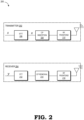
- FIG. 2 illustrates an example OFDM transceiver 200 of an ISAC system in accordance with some embodiments.
- the ISAC system is capable of implementing or facilitating wireless communications and sensing applications including radar sensing, and the OFDM transceiver 200 includes an OFDM transmitter path 202 ("transmitter 102") and an OFDM receiver path 204 ("receiver 204").
- the ISAC system operates the OFDM transceiver 200 in full duplex mode in a downlink communication phase in accordance with some embodiments. In other words, the OFDM both transmits and receives data simultaneously in a downlink communication phase.
- the transmitter 202 is illustrated to include symbols S such as sensing symbols which are represented in a first domain (e.g., a frequency domain).
- An inverse fast Fourier transform (IFFT) component 206 of the transmitter 202 represents symbols x such as the sensing symbols in a second domain (e.g., a time domain).
- the transmitter 202 also includes a cyclic prefix (CP) insertion component 208 and a RF frontend 210 in accordance with some embodiments.
- CP cyclic prefix
- the receiver 204 is illustrated as including received subcarriers y.
- the receiver 204 also includes a fast Fourier transform (FFT) component 212, a CP removal component 214, and an RF frontend 216.
- FFT fast Fourier transform
- the RF frontends 210 and 216 are typically implemented using well-known RF hardware, such as digital-to-analog converters (DACs), signal generators, modulators/mixers, low pass filters (LPFs), antenna arrays, and the like.
- DACs digital-to-analog converters
- LPFs low pass filters
- the components 206, 208, 212, and 214 each may be implemented as hardcoded logic, one or more processors executing software, programmable logic, or combinations thereof.
- FIG. 3 illustrates an example 300 of an OFDM communication symbol combined with a repetition of the OFDM communication symbol as a sensing symbol in accordance with some embodiments.
- the example 300 is illustrated to include an OFDM communication symbol 302 which has a length of C 304 + N 306 where N is the FFT size and C is the CP size.
- C ⁇ N and typically C ⁇ N.
- a signal with N samples followed by the same signal with N samples can be utilized.
- two OFDM symbols 310 are reservable in order to reserve 2 N samples 308 which is referred to as a standard sensing symbol.
- the previous OFDM communication symbol 302 is repeated to include 2 N + 2 C samples (e.g., two OFDM symbols 310), then 2N samples 308 (e.g., 2N consecutive samples) are extractable with the first N samples being a repetition of the next N samples. In this scenario, these 2 N consecutive samples are usable as a sensing symbol while only one OFDM communication symbol 302 is reserved for sensing (which is a repetition of the OFDM communication symbol 302).
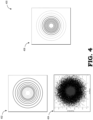
- FIG. 4 illustrates examples of attenuated subcarriers 400 for processing by an OFDM radar system to improve a signal-to-noise ratio for target estimation in accordance with some embodiments.
- a first attenuation technique particular subcarriers are set to zero (or a small value) at the transmitter 202 and/or at the receiver 204.
- the transmitter 202 instead of setting particular subcarriers to zero, it is possible to design subcarrier symbols such that the subcarrier symbols do not exhibit relatively small and/or relatively large energy values.
- the first attenuation technique applies SD or CCM.
- the examples of attenuated subcarriers 400 include a representation 402 of inner transmitter 202 subcarriers set to zero; a representation 404 of inner receiver 204 subcarriers set to zero; and a representation 406 of outer transmitter 202 subcarriers set to zero.
- the subcarriers with relatively high amplitude e.g., outer rings
- OCCM optimized CCM
- the subcarriers with relatively low energy are set to zero to avoid amplification of the noise term n s .
- Examples of low energy symbols set to zero at the transmitter 202 and at the receiver 204 are illustrated in the representations 402 and 404, respectively.
- This SD case is referred to as optimized SD (OSD).
- MMSE methods are combined with the first attenuation technique which is referred to OMMSE.
- FIG. 5 is a flow diagram of a method 500 of repeating communication OFDM symbols to compose sensing symbols and removing data information from received sensing symbols in accordance with some embodiments.
- the method 500 of FIG. 5 illustrates a general overview of the operation of the ISAC device 102 of FIGs. 1 and 2 .
- the transmitter 202 transmits an OFDM-based RF signal that serves two purposes: as a carrier of communications data for receipt by another device; and as a radar signal for radar sensing.
- the transmitter 202 receives a data input in the form of a sequence of symbols representing communication data (e.g., from an application executing at the ISAC device 102) and from this data input generates, based on OFDM principles, an RF signal (e.g., RF signal 108, FIG. 1 ) that is emitted into the local environment.
- the ISAC device 102 repurposes a portion of the receiver path along with use of the radar sensing path, to perform radar processing on RF signaling received via the receiver path as a result of scattering/reflection of RF signaling concurrently transmitted by the transmitter path.
- an input of transmission bits of a data stream is received and encoded into a data symbol on which the IFFT component 206 performs an IFFT, resulting in an OFDM symbol.
- the transmitter 202 repeats the OFDM communication symbol at block 502, and at block 504, the transmitter 202 uses both the OFDM communication symbol and the repeated OFDM communication symbol as a sensing symbol.
- the CP insertion component 208 appends (or prepends) a CP to each OFDM symbol.
- the CP is a copy of an end portion of the OFDM symbol so that a receiver receiving the resulting RF signal will be able to integrate over an integer number of sinusoid cycles for each of the multipaths when the receiver performs OFDM demodulation with a FFT.
- the OFDM symbol vector is provided to the RF frontend 210 of the transmitter path 202, whereupon the OFDM symbol vector is converted to analog signaling by a digital-to-analog (D/A) converter (not shown), the analog signaling is low-pass filtered by a low-pass filter (not shown), and the resulting filtered analog signaling is then modulated with a carrier signal having a frequency f c to generate an RF signal 108 emitted into the local environment by an antenna array of the RF frontend 210.
- the RF signal 108 then propagates one or more receiving devices (e.g., device 104, FIG. 1 ), whereupon each receiving device processes the RF signal 108 to recover the original N symbols.
- D/A digital-to-analog
- the receiver 204 Concurrently with the generation and transmission of the RF signal 108, the receiver 204 operates to generate a radar profile of the local environment using scattering/reflection of the RF signal by objects in the local environment. Accordingly, at block 508, the receiver path 204 is activated concurrent with transmission so as to receive scattered representation(s) of the RF signal 108 for radar sensing purposes. For example, when the RF signal 108 encounters an object 106 ( FIG. 1 ) in the local environment, the object 106 scatters the RF signal 108, resulting in a scattered RF signal 110 propagating back to the ISAC device 102 and being received at the RF frontend 216 of the receiver path 204. The RF frontend 216 converts the scattered RF signal 110 from an analog signal to a digital signal, which is parallelized into N channels, with each channel representing a recovered symbol and a corresponding appended CP.
- the CP removal component 214 removes the CPs and component 212 applies an FFT. Also at block 510, some high and/or low amplitude subcarriers are attenuated. For example, in some embodiments, if the receiver 204 applies CCM to obtain the channel estimation ⁇ , the receiver 204 sets rings having an amplitude above a first threshold to zero (or a small value) to avoid amplification of the noise term s*n. In some embodiments, if the receiver 204 applies SD to obtain the channel estimation ⁇ , the receiver 204 sets rings having an amplitude below a second threshold to zero (or a small value) to avoid amplification of the noise term n s .
- the method flow continues to block 512, representing OCCM. If the receiver applies SD to obtain the channel estimation ⁇ , the method flow continues to block 514, representing OSD. If the receiver applies MMSE to obtain the channel estimation ⁇ , the method flow continues to block 516, representing OMMSE.
- the subcarrier symbols are designed such that they do not assume small and/or large energy values.
- the result is an estimation of the transfer function of the propagation path, that is, of the local environment with the scattering object 106.
- the radar sensing path operates to extract a representation of this transfer function for the local environment based on correlation between the original OFDM symbol and the received OFDM symbol, and from this representation of the transfer function determine one or both of the range and velocity of scattering objects, such as scattering object 106, within the local environment, as described herein.
- FIG. 6 illustrates an example plot 600 of average target signal-to-noise ratios after applying signal processing for OFDM radar systems in accordance with some embodiments.
- the plot 600 includes average target signal-to-noise ratios for a given channel signal-to-noise ratio for SD 602, CCM 604, MMSE 606, OSD 608, OCCM 610, and OMMSE 612.
- SD 602 is outperformed by CCM 604 and OMMSE 612.
- SD 602 converges to OMMSE 612 and CCM 604 is outperformed by both SD 602 and OMMSE 612.
- OSD 608 When applying OSD 608 by setting to zero constellation points below a first energy threshold (e.g., the first energy threshold is determined heuristically based on particular environmental characteristics and/or specific sensing applications and may be recalibrated based on changes in environmental characteristics and/or sensing applications), OSD 608 closely follows performance of OMMSE 612 even at low signal-to-noise ratios.
- a second energy threshold e.g., the second energy threshold is determined heuristically based on particular environmental characteristics and/or specific sensing applications and may be recalibrated based on changes in environmental characteristics and/or sensing applications
- the performance of OCCM 610 closely follows CCM 604.
- OSD 608, OCCM 610, and OMMSE 612 are similar to performances illustrated by other curves included in plot 600, removal of the subcarriers to be processed could lead to less overall complexity (e.g., a reduction in complexity).
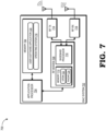
- FIG. 7 illustrates an example hardware implementation 700 of an ISAC system 702 in accordance with some embodiments.
- the ISAC system 702 includes at least one application processor 704 (e.g., a central processing unit (CPU) or other general processor), a system memory 706, one or more RF modems 708, a transmitter (TX) RF frontend 714 (e.g., one embodiment of the RF frontend 210) and a receiver (RX) RF frontend 716 (e.g., one embodiment of the RF frontend 216).
- TX transmitter
- RX receiver
- the RF modem 708 includes a baseband processor 710 and a memory 712, which can include, for example, a Flash memory, non-volatile random-access memory (NVRAM) or other non-volatile memory, or static RAM (SRAM) or dynamic RAM (DRAM) or other volatile memory, or a combination thereof.
- NVRAM non-volatile random-access memory
- SRAM static RAM
- DRAM dynamic RAM
- the ISAC system 702 can include a number of additional components omitted from FIG.
- a transmitter system e.g., including an encoder, a modulator, an OFDM generator, etc.
- a radar sensing system e.g., including one or more antennae, a duplexer, a radar transceiver, a radar signal processing component, a radar control component, etc.
- a receiver system e.g., including an OFDM demodulator, a decoder, a radar data processing component, etc.
- one or more displays one or more touchscreens, keypads, mice, touchpads, microphones, speakers, and other user input/output devices, one or more sensors, batteries or other power sources, graphical processing units (GPUs) or other coprocessors, and the like.
- GPUs graphical processing units
- the application processor 704 executes executable instructions from a software stack that includes an operating system (OS) 718 and one or more user software applications, such as user software application 720, and which further can include protocol stacks executed by the baseband processor 710 of the RF modem(s) 708.
- OS operating system
- user software application 720 user software application 720
- protocol stacks executed by the baseband processor 710 of the RF modem(s) 708.
- the OS 718 through manipulation of the application processor 704, manages the general operation of the various hardware components of the ISAC system 702 as well as supports the execution of the one or more user software applications, with the executable instructions representing the OS 718 and the user software application typically accessed from system memory 706 for execution by the application processor 704.
- the memory 712 of the RF modem 708 stores one or more sets of executable instructions that, when executed by the baseband processor 710, manipulate the baseband processor 710 to perform various operations in accordance with one or more communication protocols associated with the air interfaces provided by RF frontends 714 and 716.
- These operations can include various OFDM-related operations performed by execution of OFDM software 722, such as the operations described above with reference to the components 206, 208, 212, and 214 and radar sensing operations performed by execution of radar sensing software 724.
- one or more operations are performed by an application processor 704 (or a dedicated processor, such as a graphics processing unit, or GPU) executing software stored in the system memory 706.
- the OFDM-related operations of the transmitter 202 and the receiver 204 may be performed at one or more RF modems 708.
- an OFDM transceiver of an ISAC system is operated in full-duplex mode in a downlink communication phase.
- the ISAC system generates sensing symbols for an OFDM radar system by combining OFDM communication symbols and repetitions of the OFDM communication symbols as the sensing symbols.
- the OFDM transceiver attenuates subcarriers of received sensing symbols for processing by the OFDM radar system to increase a signal-to-noise ratio of the received sensing symbols.
Landscapes
- Engineering & Computer Science (AREA)
- Computer Networks & Wireless Communication (AREA)
- Signal Processing (AREA)
- Radar, Positioning & Navigation (AREA)
- Remote Sensing (AREA)
- Physics & Mathematics (AREA)
- General Physics & Mathematics (AREA)
- Power Engineering (AREA)
- Radar Systems Or Details Thereof (AREA)
Abstract
In implementations of signal processing for OFDM radar systems, an OFDM transceiver of an ISAC system is operated in full-duplex mode in a downlink communication phase. The ISAC system generates sensing symbols for an OFDM radar system by combining OFDM communication symbols and repetitions of the OFDM communication symbols as the sensing symbols. The OFDM transceiver attenuates subcarriers of received sensing symbols for processing by the OFDM radar system to increase a signal-to-noise ratio of the received sensing symbols.
Description
- Integrated sensing and communication (ISAC) systems leverage wireless communication systems and sensor systems to facilitate both communications and radar sensing such that information collected from the radar sensing systems can be efficiently communicated to other devices or systems via the communication systems. When performing ISAC, there is typically at least some trade-off between the sensing and communication applications. For example, utilization of sensing symbols for radar sensing is additional overhead for the communications systems. In another trade-off example, techniques for reducing this overhead for the communications systems can introduce a low target signal-to-noise ratio for target estimation in the sensing systems.
- Aspect of the disclosure are defined in the accompanying claims.
- In a first aspect, there is provided a method comprising: operating, by an integrated sensing and communication (ISAC) system, an orthogonal frequency division multiplication (OFDM) transceiver in full-duplex mode in a downlink communication phase; generating, by the ISAC system, sensing symbols for an OFDM radar system by combining communication symbols and repetitions of the communication symbols as the sensing symbols.
- In some embodiments, the method further comprises: attenuating, by the OFDM transceiver in the full-duplex mode, subcarriers of received sensing symbols for processing by the OFDM radar system to increase a signal-to-noise ratio of the received sensing symbols.
- In some embodiments, attenuating the subcarriers removes the subcarriers from the received sensing symbols.
- In some embodiments, the subcarriers are attenuated at one or both of a transmitter and a receiver of the OFDM transceiver.
- In some embodiments, the subcarriers are attenuated and complex conjugate multiplication (CCM) is used to obtain channel information.
- In some embodiments, the subcarriers are attenuated based on having amplitudes that are greater than a high amplitude threshold.
- In some embodiments, the subcarriers are attenuated and spectral division (SD) is used to obtain channel information.
- In some embodiments, the subcarriers are attenuated based on having amplitudes that are less than a low amplitude threshold.
- In some embodiments, the method further comprises: processing the received sensing symbols based on minimum mean square error (MMSE) estimation.
- In a second aspect, there is provided an ISAC system comprising: an OFDM radar system configured to process sensing symbols generated by combining communication symbols and repetitions of the communication symbols as the sensing symbols; and an OFDM transceiver configured to: operate in full-duplex mode in a downlink communication phase.
- In some embodiments, the OFDM transceiver is further configured to: attenuate subcarriers of received sensing symbols for processing by the OFDM radar system to increase a signal-to-noise ratio of the received sensing symbols.
- In some embodiments, the subcarriers are attenuated at one or both of a transmitter and a receiver of the OFDM transceiver.
- In some embodiments, the subcarriers are attenuated using CCM based on having amplitudes that are greater than a high amplitude threshold.
- In some embodiments, the subcarriers are attenuated using SD based on having amplitudes that are less than a low amplitude threshold.
- In some embodiments, attenuating the subcarriers removes the subcarriers from the received sensing symbols.
- In some embodiments, the OFDM radar is configured to process the received sensing symbols based on MMSE estimation.
- In a third aspect, there is provided a non-transitory computer-readable medium storing a set of executable instructions, the set of executable instructions to manipulate at least one processor to: operate an OFDM transceiver of an ISAC system in full-duplex mode in a downlink communication phase; generate sensing symbols for an OFDM radar system of the ISAC system by combining communication symbols and repetitions of the communication symbols as the sensing symbols; and attenuate subcarriers of received sensing symbols for processing by the OFDM radar system to increase a signal-to-noise ratio of the received sensing symbols.
- In some embodiments of the non-transitory computer-readable medium, the subcarriers are attenuated using CCM based on having amplitudes that are greater than a high amplitude threshold.
- In some embodiments of the non-transitory computer-readable medium, the subcarriers are attenuated using SD based on having amplitudes that are less than a low amplitude threshold.
- In some embodiments of the non-transitory computer-readable medium, the set of executable instructions are configured to further manipulate the at least one processor to: process the received sensing symbols based on MMSE estimation.
- The present disclosure may be better understood, and its numerous features and advantages made apparent to those skilled in the art by referencing the accompanying drawings. The use of the same reference symbols in different drawings indicates similar or identical items.
-
FIG. 1 is a diagram illustrating an ISAC or joint communication and sensing (JCAS) system utilizing OFDM signaling for both communications and radar sensing in accordance with some embodiments. -
FIG. 2 is a diagram illustrating an OFDM transceiver of an ISAC system in accordance with some embodiments. -
FIG. 3 is a diagram illustrating an OFDM communication symbol combined with a repetition of the OFDM communication symbol as a sensing symbol in accordance with some embodiments. -
FIG. 4 is a diagram illustrating attenuated subcarriers for processing by an OFDM radar system to improve a signal-to-noise ratio for target estimation in accordance with some embodiments. -
FIG. 5 is a flow diagram of a method of repeating communication OFDM symbols to compose sensing symbols and removing data information from received sensing symbols in accordance with some embodiments. -
FIG. 6 is a diagram illustrating a plot of average target signal-to-noise ratios after applying signal processing for OFDM radar systems in accordance with some embodiments. -
FIG. 7 is a diagram illustrating an example hardware implementation of an ISAC system in accordance with some embodiments. - ISAC systems are capable of facilitating both communications and radar sensing such that information collected from the radar sensing can be efficiently communicated to other devices or systems. For example, an ISAC system that includes a base station utilizing range and Doppler measurements as part of a radar sensing system estimates distances and velocities of objects (e.g., pedestrians) in a local environment, and then the ISAC system communicates the estimated distances and velocities to an autonomous vehicle via a communications system. In this example, the autonomous vehicle receives and processes the communicated information to improve adaptive cruise control, collision warning functionalities, and the like.
- An ISAC system includes a transmitting device that generates and transmits an OFDM signal representing a sequence of OFDM symbols, which in turn represent a set of communication data. The OFDM signal (bitstream) representing the communication data is divided into multiple streams, and multiple orthogonal subcarrier signals with overlapping spectra are also transmitted, with each carrier modulated with symbols from the incoming stream so multiple symbols are being transmitted in parallel. The OFDM signal is received at a receiving device, which processes the OFDM signal to extract the set of communication data represented by the OFDM signal. The OFDM signal is also scattered by at least one object in the local environment of the transmitting device. The receiving device thus may also receive the scattered OFDM signal and extract the OFDM symbols represented in the scattered OFDM signal. By comparing the differences between the originally transmitted OFDM symbols and the received OFDM symbols, the transmitting device can estimate the distance and speed of the object.
- When implementing ISAC systems, there are usually some trade-offs between the sensing and communication applications. In an example of these trade-offs, symbols that are reserved for radar sensing cannot also be used for communications, so fewer symbols (and, by extension, data) are available for communications. In another trade-off example, techniques for reducing this overhead for the communications systems can introduce a low target signal-to-noise ratio for target estimation in the sensing systems.
- In order to overcome the limitations of conventional ISAC systems, in some embodiments a repetition of a communication symbol is used as the sensing symbol, thus freeing up more symbols for to be used as communication symbols. In some embodiments, particular subcarriers are attenuated at a transmitter and/or at a receiver of a OFDM transceiver of an ISAC system. In an example, the particular subcarriers are attenuated by setting to zero the particular subcarriers or by designing subcarrier symbols such that the subcarrier symbols do not exhibit relatively small and/or relatively large energy values. In this example, first techniques for CCM or SD are applied.
- In the case of CCM, subcarriers with relatively high amplitude are set to zero to avoid amplification of noise terms and distortions on the channel estimation. The CCM case is referred to as optimized CCM (OCCM). In the case of SD, subcarriers with relatively low energy and/or relatively high energy are set to zero to avoid amplification of noise terms. The SD case is referred to as optimized SD (OSD).
- A second technique utilizing MMSE methods is combined with the first techniques resulting in optimized MMSE (OMMSE). In accordance with some embodiments of the second technique, if noise power is high, then estimation tends to CCM, and if noise power is low, then estimation tends to SD. Evaluations of OSD, OCCM, and OMMSE demonstrate similar performance to conventional techniques, and removal of subcarriers to be processed can result in an overall reduction in complexity.
-
FIG. 1 illustrates an example ISAC or JCAS system 100 (referred to herein as the ISAC system 100) utilizing integrated or concurrent radar sensing and communication with repetition of communication symbols as sensing symbols and attenuation of subcarriers in accordance with some embodiments. TheISAC system 100 includes anISAC device 102 employing OFDM signaling for both transmission of data to at least asecond device 104 and for radar sensing of objects, such asobject 106, in a local environment of theISAC device 102. To illustrate, the ISACsystem 100 may be a cellular system in which theISAC device 102 is a base station and thedevice 104 is a user equipment (UE), with the base station utilizing OFDM signaling to communicate data to the UE in accordance with, for example, a Fourth Generation Long Term Evolution (4G LTE) cellular protocol or a Third Generation Partnership Protocol (3GPP) Fifth Generation New Radio (5G NR) protocol, while also attempting to sense the range and velocity of objects in the local environment utilizing the same OFDM signaling. Alternatively, the ISACdevice 102 could be the UE and thedevice 104 the base station. As yet another example, theISAC system 100 could be a wireless local area network (WLAN) system using OFDM-based IEEE 802.11 wireless transmissions to communicate data with thedevice 104 in the form of a UE, while also using the same OFDM signaling to sense objects in the local environment. - In operation, the
ISAC device 102 converts a set of data for transmission to thedevice 104 to a sequence of one or more OFDM symbols, which is then converted to an analog signal that is modulated with a carrier frequency signal to generate a radio frequency (RF) signal 108, which is emitted by theISAC device 102 and propagated through the local environment. Thedevice 104 receives the emitted RF signal 108 and processes the RF signal 108 to extract the set of data for further processing. Further, the emitted RF signal 108 is scattered by objects in the local environment, such as object 106 (e.g., a vehicle). The resultingscattered RF signal 110 is propagated to theISAC device 102, whereupon theISAC device 102 processes thescattered RF signal 110 to determine either or both of a range (distance) or a velocity of theobject 106 relative to the ISAC device 102 (as range/doppler data 112) using the techniques described herein. The range/doppler data 112 then may be used by theISAC device 102 to modify one or more of its operations. For example, the range/doppler data 112 may inform theISAC device 102 of a relative location of an interfering object, in response to which theISAC device 102 may modify one or more of its transmission parameters, such as transmission power, beam direction, etc., to compensate for the interfering object. As another example, theISAC device 102 may be a vehicle that implements some form of autonomous driving, and the relative distance and speed of objects identified in the range/doppler data 112 may inform one or more driving operations of the vehicle. Still further, theISAC device 102 may transmit the range/doppler data 112 to other devices for their own use. -
FIG. 2 illustrates anexample OFDM transceiver 200 of an ISAC system in accordance with some embodiments. The ISAC system is capable of implementing or facilitating wireless communications and sensing applications including radar sensing, and theOFDM transceiver 200 includes an OFDM transmitter path 202 ("transmitter 102") and an OFDM receiver path 204 ("receiver 204"). The ISAC system operates theOFDM transceiver 200 in full duplex mode in a downlink communication phase in accordance with some embodiments. In other words, the OFDM both transmits and receives data simultaneously in a downlink communication phase. - The
transmitter 202 is illustrated to include symbols S such as sensing symbols which are represented in a first domain (e.g., a frequency domain). An inverse fast Fourier transform (IFFT)component 206 of thetransmitter 202 represents symbols x such as the sensing symbols in a second domain (e.g., a time domain). Thetransmitter 202 also includes a cyclic prefix (CP)insertion component 208 and aRF frontend 210 in accordance with some embodiments. - The
receiver 204 is illustrated as including received subcarriers y. In an example, the received subcarriers y can be described as:
- The
receiver 204 also includes a fast Fourier transform (FFT)component 212, aCP removal component 214, and anRF frontend 216. TheRF frontends components -
FIG. 3 illustrates an example 300 of an OFDM communication symbol combined with a repetition of the OFDM communication symbol as a sensing symbol in accordance with some embodiments. The example 300 is illustrated to include anOFDM communication symbol 302 which has a length ofC 304 +N 306 where N is the FFT size and C is the CP size. In accordance with some embodiments, C ≤ N and typically C << N. In order to estimate up to a maximum unambiguous distance for OFDM radar sensing (e.g., totaling 2N samples 308), a signal with N samples followed by the same signal with N samples can be utilized. In a scenario in which a sensing symbol is not a communication symbol, twoOFDM symbols 310 are reservable in order to reserve 2Nsamples 308 which is referred to as a standard sensing symbol. - If the previous
OFDM communication symbol 302 is repeated to include 2N + 2C samples (e.g., two OFDM symbols 310), then 2N samples 308 (e.g., 2N consecutive samples) are extractable with the first N samples being a repetition of the next N samples. In this scenario, these 2N consecutive samples are usable as a sensing symbol while only oneOFDM communication symbol 302 is reserved for sensing (which is a repetition of the OFDM communication symbol 302). - Returning to the example in which the received subcarriers y are describable as:

- In accordance with some embodiments, two example techniques are described for extracting the channel information h. In the first example technique, CCM of the transmitted N samples of sensing subcarriers in the frequency domain by y is representable as:

- In the second example technique, SD is utilized to divide the received subcarriers y by the transmitted subcarriers s in the frequency domain which is describable as:

-
FIG. 4 illustrates examples ofattenuated subcarriers 400 for processing by an OFDM radar system to improve a signal-to-noise ratio for target estimation in accordance with some embodiments. In a first attenuation technique, particular subcarriers are set to zero (or a small value) at thetransmitter 202 and/or at thereceiver 204. Alternatively, at thetransmitter 202, instead of setting particular subcarriers to zero, it is possible to design subcarrier symbols such that the subcarrier symbols do not exhibit relatively small and/or relatively large energy values. In either alternative, the first attenuation technique applies SD or CCM. - The examples of
attenuated subcarriers 400 include arepresentation 402 ofinner transmitter 202 subcarriers set to zero; arepresentation 404 ofinner receiver 204 subcarriers set to zero; and arepresentation 406 ofouter transmitter 202 subcarriers set to zero. In the case of CCM, the subcarriers with relatively high amplitude (e.g., outer rings) are set to zero to avoid amplification of the noise term s*n. This CCM case is referred to as optimized CCM (OCCM). - In the case of SD, the subcarriers with relatively low energy (e.g., inner rings) are set to zero to avoid amplification of the noise term

transmitter 202 and at thereceiver 204 are illustrated in therepresentations - In a second attenuation technique, MMSE methods are combined with the first attenuation technique which is referred to OMMSE. The estimation ĥ by a pure MMSE is describable as:

-
FIG. 5 is a flow diagram of amethod 500 of repeating communication OFDM symbols to compose sensing symbols and removing data information from received sensing symbols in accordance with some embodiments. Themethod 500 ofFIG. 5 illustrates a general overview of the operation of theISAC device 102 ofFIGs. 1 and2 . At startup or for the initiation of the process for transmission of an OFDM frame containing OFDM symbols representing communication data, thetransmitter 202 transmits an OFDM-based RF signal that serves two purposes: as a carrier of communications data for receipt by another device; and as a radar signal for radar sensing. As such, thetransmitter 202 receives a data input in the form of a sequence of symbols representing communication data (e.g., from an application executing at the ISAC device 102) and from this data input generates, based on OFDM principles, an RF signal (e.g., RF signal 108,FIG. 1 ) that is emitted into the local environment. For radar sensing, theISAC device 102 repurposes a portion of the receiver path along with use of the radar sensing path, to perform radar processing on RF signaling received via the receiver path as a result of scattering/reflection of RF signaling concurrently transmitted by the transmitter path. - Starting with the transmission process, at
block 502, an input of transmission bits of a data stream is received and encoded into a data symbol on which theIFFT component 206 performs an IFFT, resulting in an OFDM symbol. Thetransmitter 202 repeats the OFDM communication symbol atblock 502, and atblock 504, thetransmitter 202 uses both the OFDM communication symbol and the repeated OFDM communication symbol as a sensing symbol. - After the IFFT process, at
block 506 theCP insertion component 208 appends (or prepends) a CP to each OFDM symbol. Typically, the CP is a copy of an end portion of the OFDM symbol so that a receiver receiving the resulting RF signal will be able to integrate over an integer number of sinusoid cycles for each of the multipaths when the receiver performs OFDM demodulation with a FFT. - Following CP insertion, the OFDM symbol vector is provided to the RF frontend 210 of the
transmitter path 202, whereupon the OFDM symbol vector is converted to analog signaling by a digital-to-analog (D/A) converter (not shown), the analog signaling is low-pass filtered by a low-pass filter (not shown), and the resulting filtered analog signaling is then modulated with a carrier signal having a frequency fc to generate an RF signal 108 emitted into the local environment by an antenna array of theRF frontend 210. The RF signal 108 then propagates one or more receiving devices (e.g.,device 104,FIG. 1 ), whereupon each receiving device processes the RF signal 108 to recover the original N symbols. - Concurrently with the generation and transmission of the RF signal 108, the
receiver 204 operates to generate a radar profile of the local environment using scattering/reflection of the RF signal by objects in the local environment. Accordingly, atblock 508, thereceiver path 204 is activated concurrent with transmission so as to receive scattered representation(s) of the RF signal 108 for radar sensing purposes. For example, when the RF signal 108 encounters an object 106 (FIG. 1 ) in the local environment, theobject 106 scatters the RF signal 108, resulting in a scattered RF signal 110 propagating back to theISAC device 102 and being received at the RF frontend 216 of thereceiver path 204. The RF frontend 216 converts the scattered RF signal 110 from an analog signal to a digital signal, which is parallelized into N channels, with each channel representing a recovered symbol and a corresponding appended CP. - At
block 510, theCP removal component 214 removes the CPs andcomponent 212 applies an FFT. Also atblock 510, some high and/or low amplitude subcarriers are attenuated. For example, in some embodiments, if thereceiver 204 applies CCM to obtain the channel estimation ĥ, thereceiver 204 sets rings having an amplitude above a first threshold to zero (or a small value) to avoid amplification of the noise term s*n. In some embodiments, if thereceiver 204 applies SD to obtain the channel estimation ĥ, thereceiver 204 sets rings having an amplitude below a second threshold to zero (or a small value) to avoid amplification of the noise term
receiver 204 applies CCM to obtain the channel estimation ĥ, the method flow continues to block 512, representing OCCM. If the receiver applies SD to obtain the channel estimation ĥ , the method flow continues to block 514, representing OSD. If the receiver applies MMSE to obtain the channel estimation ĥ, the method flow continues to block 516, representing OMMSE. In some embodiments, at thetransmitter 202 side, the subcarrier symbols are designed such that they do not assume small and/or large energy values. - After applying one of the
blocks scattering object 106. Thus, the radar sensing path operates to extract a representation of this transfer function for the local environment based on correlation between the original OFDM symbol and the received OFDM symbol, and from this representation of the transfer function determine one or both of the range and velocity of scattering objects, such as scatteringobject 106, within the local environment, as described herein. -
FIG. 6 illustrates anexample plot 600 of average target signal-to-noise ratios after applying signal processing for OFDM radar systems in accordance with some embodiments. Theplot 600 includes average target signal-to-noise ratios for a given channel signal-to-noise ratio forSD 602,CCM 604,MMSE 606,OSD 608,OCCM 610, andOMMSE 612. As shown in theexample plot 600, at low channel signal-to-noise ratios,SD 602 is outperformed byCCM 604 andOMMSE 612. At high channel signal-to-noise ratios,SD 602 converges to OMMSE 612 andCCM 604 is outperformed by bothSD 602 andOMMSE 612. - When applying
OSD 608 by setting to zero constellation points below a first energy threshold (e.g., the first energy threshold is determined heuristically based on particular environmental characteristics and/or specific sensing applications and may be recalibrated based on changes in environmental characteristics and/or sensing applications),OSD 608 closely follows performance ofOMMSE 612 even at low signal-to-noise ratios. When applyingOCCM 610 by setting to zero constellation points above a second energy threshold (e.g., the second energy threshold is determined heuristically based on particular environmental characteristics and/or specific sensing applications and may be recalibrated based on changes in environmental characteristics and/or sensing applications), the performance ofOCCM 610 closely followsCCM 604. Notably, although the performances ofOSD 608,OCCM 610, andOMMSE 612 are similar to performances illustrated by other curves included inplot 600, removal of the subcarriers to be processed could lead to less overall complexity (e.g., a reduction in complexity). -
FIG. 7 illustrates anexample hardware implementation 700 of anISAC system 702 in accordance with some embodiments. In the depicted example, theISAC system 702 includes at least one application processor 704 (e.g., a central processing unit (CPU) or other general processor), asystem memory 706, one ormore RF modems 708, a transmitter (TX) RF frontend 714 (e.g., one embodiment of the RF frontend 210) and a receiver (RX) RF frontend 716 (e.g., one embodiment of the RF frontend 216). Although asingle RF modem 708 is illustrated as supporting operation of bothRF frontends dedicated RF modem 708. TheRF modem 708 includes abaseband processor 710 and amemory 712, which can include, for example, a Flash memory, non-volatile random-access memory (NVRAM) or other non-volatile memory, or static RAM (SRAM) or dynamic RAM (DRAM) or other volatile memory, or a combination thereof. Further, it will be appreciated that theISAC system 702 can include a number of additional components omitted fromFIG. 7 for ease of illustration including, for example, a transmitter system (e.g., including an encoder, a modulator, an OFDM generator, etc.), a radar sensing system (e.g., including one or more antennae, a duplexer, a radar transceiver, a radar signal processing component, a radar control component, etc.), a receiver system (e.g., including an OFDM demodulator, a decoder, a radar data processing component, etc.), one or more displays, one or more touchscreens, keypads, mice, touchpads, microphones, speakers, and other user input/output devices, one or more sensors, batteries or other power sources, graphical processing units (GPUs) or other coprocessors, and the like. - The
application processor 704 executes executable instructions from a software stack that includes an operating system (OS) 718 and one or more user software applications, such as user software application 720, and which further can include protocol stacks executed by thebaseband processor 710 of the RF modem(s) 708. TheOS 718, through manipulation of theapplication processor 704, manages the general operation of the various hardware components of theISAC system 702 as well as supports the execution of the one or more user software applications, with the executable instructions representing theOS 718 and the user software application typically accessed fromsystem memory 706 for execution by theapplication processor 704. - Further, the
memory 712 of theRF modem 708 stores one or more sets of executable instructions that, when executed by thebaseband processor 710, manipulate thebaseband processor 710 to perform various operations in accordance with one or more communication protocols associated with the air interfaces provided byRF frontends OFDM software 722, such as the operations described above with reference to thecomponents radar sensing software 724. In other embodiments, one or more operations are performed by an application processor 704 (or a dedicated processor, such as a graphics processing unit, or GPU) executing software stored in thesystem memory 706. For example, the OFDM-related operations of thetransmitter 202 and thereceiver 204 may be performed at one or more RF modems 708. - In implementations of signal processing for OFDM radar systems, an OFDM transceiver of an ISAC system is operated in full-duplex mode in a downlink communication phase. The ISAC system generates sensing symbols for an OFDM radar system by combining OFDM communication symbols and repetitions of the OFDM communication symbols as the sensing symbols. The OFDM transceiver attenuates subcarriers of received sensing symbols for processing by the OFDM radar system to increase a signal-to-noise ratio of the received sensing symbols.
- Note that not all of the activities or elements described above in the general description are required, that a portion of a specific activity or device may not be required, and that one or more further activities may be performed, or elements included, in addition to those described. Still further, the order in which activities are listed are not necessarily the order in which they are performed. Also, the concepts have been described with reference to specific embodiments. However, one of ordinary skill in the art appreciates that various modifications and changes can be made without departing from the scope of the present disclosure as set forth in the claims below. Accordingly, the specification and figures are to be regarded in an illustrative rather than a restrictive sense, and all such modifications are intended to be included within the scope of the present disclosure.
- Benefits, other advantages, and solutions to problems have been described above with regard to specific embodiments. However, the benefits, advantages, solutions to problems, and any feature(s) that may cause any benefit, advantage, or solution to occur or become more pronounced are not to be construed as a critical, required, or essential feature of any or all the claims. Moreover, the particular embodiments disclosed above are illustrative only, as the disclosed subject matter may be modified and practiced in different but equivalent manners apparent to those skilled in the art having the benefit of the teachings herein. No limitations are intended to the details of construction or design herein shown, other than as described in the claims below. It is therefore evident that the particular embodiments disclosed above may be altered or modified and all such variations are considered within the scope of the disclosed subject matter. Accordingly, the protection sought herein is as set forth in the claims below.
Claims (15)
- A method comprising:operating, by an integrated sensing and communication (ISAC) system, an orthogonal frequency division multiplication (OFDM) transceiver in full-duplex mode in a downlink communication phase; andgenerating, by the ISAC system, sensing symbols for an OFDM radar system by combining communication symbols and repetitions of the communication symbols.
- The method of claim 1, further comprising:
attenuating, by the OFDM transceiver in the full-duplex mode, subcarriers of received sensing symbols for processing by the OFDM radar system. - The method of claim 2, wherein attenuating the subcarriers removes the subcarriers from the received sensing symbols.
- The method of claim 2 or 3, wherein the subcarriers are attenuated at one or both of a transmitter and a receiver of the OFDM transceiver.
- The method of any of claims 2 to 4, wherein the subcarriers are attenuated and complex conjugate multiplication (CCM) is applied.
- The method of claim 5, wherein the subcarriers are attenuated based on having amplitudes that are greater than a high amplitude threshold.
- The method of any of claims 2 to 6, wherein the subcarriers are attenuated and spectral division (SD) is applied.
- The method of claim 7, wherein the subcarriers are attenuated based on having amplitudes that are less than a low amplitude threshold.
- The method of any preceding claim, further comprising:
processing the received sensing symbols based on minimum mean square error (MMSE) estimation. - An integrated sensing and communication (ISAC) system comprising:an orthogonal frequency division multiplication (OFDM) radar system configured to process sensing symbols comprising communication symbols and repetitions of the communication symbols; andan OFDM transceiver configured to:
operate in full-duplex mode in a downlink communication phase. - The ISAC system of claim 10, wherein the OFDM transceiver is further configured to:
attenuate subcarriers of received sensing symbols for processing by the OFDM radar system to increase a signal-to-noise ratio of the received sensing symbols. - The ISAC system of claim 11, wherein the subcarriers are attenuated at one or both of a transmitter and a receiver of the OFDM transceiver.
- The ISAC system of claim 11 or 12, wherein the subcarriers are attenuated using complex conjugate multiplication (CCM) based on having amplitudes that are greater than a high amplitude threshold.
- The ISAC system of any of claims 11 to 13, wherein the subcarriers are attenuated using spectral division (SD) based on having amplitudes that are less than a low amplitude threshold.
- The ISAC system of any of claims 11 to 14, wherein attenuating the subcarriers removes the subcarriers from the received sensing symbols.
Applications Claiming Priority (1)
| Application Number | Priority Date | Filing Date | Title |
|---|---|---|---|
| US18/368,614 US12625230B2 (en) | 2023-09-15 | 2023-09-15 | Signal processing for OFDM radar systems |
Publications (1)
| Publication Number | Publication Date |
|---|---|
| EP4524602A1 true EP4524602A1 (en) | 2025-03-19 |
Family
ID=92626769
Family Applications (1)
| Application Number | Title | Priority Date | Filing Date |
|---|---|---|---|
| EP24197375.9A Pending EP4524602A1 (en) | 2023-09-15 | 2024-08-29 | Signal processing for ofdm radar systems |
Country Status (3)
| Country | Link |
|---|---|
| US (1) | US12625230B2 (en) |
| EP (1) | EP4524602A1 (en) |
| CN (1) | CN119652718A (en) |
Citations (3)
| Publication number | Priority date | Publication date | Assignee | Title |
|---|---|---|---|---|
| US20210382160A1 (en) * | 2019-03-07 | 2021-12-09 | Robert Bosch Gmbh | Method for operating an ofdm radar system |
| WO2023011560A1 (en) * | 2021-08-05 | 2023-02-09 | 华为技术有限公司 | Communication method and related apparatus |
| WO2023164342A1 (en) * | 2022-02-24 | 2023-08-31 | Qualcomm Incorporated | Waveform for joint communications and radio frequency (rf) sensing |
Family Cites Families (17)
| Publication number | Priority date | Publication date | Assignee | Title |
|---|---|---|---|---|
| KR101002873B1 (en) * | 2003-11-20 | 2010-12-21 | 학교법인 포항공과대학교 | Signal receiving device and method in OPDM communication system |
| US8797208B2 (en) * | 2010-12-13 | 2014-08-05 | Sony Corporation | Active radar system and method |
| DE102011009874B3 (en) * | 2011-01-31 | 2012-04-12 | Karlsruher Institut für Technologie | Method for transmitting signal separation in a radar system and radar system |
| US10126421B2 (en) * | 2015-05-15 | 2018-11-13 | Maxlinear, Inc. | Dynamic OFDM symbol shaping for radar applications |
| US10361766B2 (en) * | 2017-05-10 | 2019-07-23 | The United States Of America As Represented By The Secretary Of The Air Force | Space-time coding with signal separation |
| US11644529B2 (en) * | 2018-03-26 | 2023-05-09 | Qualcomm Incorporated | Using a side-communication channel for exchanging radar information to improve multi-radar coexistence |
| US10938615B2 (en) * | 2018-04-02 | 2021-03-02 | Maxlinear, Inc. | Signaling in an orthogonal frequency division multiplexed radar system |
| US10955547B2 (en) * | 2018-05-24 | 2021-03-23 | The Boeing Company | Combined radar and communications system using common signal waveform |
| US11280876B2 (en) * | 2018-06-18 | 2022-03-22 | Qualcomm Incorporated | Multi-radar coexistence using phase-coded frequency modulated continuous wave waveforms |
| US11385323B2 (en) * | 2018-06-25 | 2022-07-12 | Qualcomm Incorporated | Selection of frequency modulated continuous wave (FMWC) waveform parameters for multi-radar coexistence |
| US11585889B2 (en) * | 2018-07-25 | 2023-02-21 | Qualcomm Incorporated | Methods for radar coexistence |
| EP3627787B1 (en) * | 2018-09-22 | 2023-01-25 | IMEC vzw | Ofdm based radar detection |
| US11454696B2 (en) * | 2019-04-05 | 2022-09-27 | Infineon Technologies Ag | FMCW radar integration with communication system |
| DE102019209310A1 (en) * | 2019-06-27 | 2020-12-31 | Robert Bosch Gmbh | OFDM radar sensor system with actively retransmitting repeater |
| US11796631B2 (en) * | 2019-08-05 | 2023-10-24 | Electronics And Telecommunications Research Institute | Method of transmitting and receiving OFDM signal for radar applications and apparatuses performing the method |
| DE102019126988A1 (en) * | 2019-10-08 | 2021-04-08 | Friedrich-Alexander-Universität Erlangen-Nürnberg | Method for reducing interference in a radar system |
| US12339387B2 (en) * | 2022-05-03 | 2025-06-24 | Qualcomm Incorporated | GI-FMCW radar reference signal design for joint communication-radar |
-
2023
- 2023-09-15 US US18/368,614 patent/US12625230B2/en active Active
-
2024
- 2024-08-29 EP EP24197375.9A patent/EP4524602A1/en active Pending
- 2024-09-12 CN CN202411277477.4A patent/CN119652718A/en active Pending
Patent Citations (3)
| Publication number | Priority date | Publication date | Assignee | Title |
|---|---|---|---|---|
| US20210382160A1 (en) * | 2019-03-07 | 2021-12-09 | Robert Bosch Gmbh | Method for operating an ofdm radar system |
| WO2023011560A1 (en) * | 2021-08-05 | 2023-02-09 | 华为技术有限公司 | Communication method and related apparatus |
| WO2023164342A1 (en) * | 2022-02-24 | 2023-08-31 | Qualcomm Incorporated | Waveform for joint communications and radio frequency (rf) sensing |
Also Published As
| Publication number | Publication date |
|---|---|
| US12625230B2 (en) | 2026-05-12 |
| US20250093461A1 (en) | 2025-03-20 |
| CN119652718A (en) | 2025-03-18 |
Similar Documents
| Publication | Publication Date | Title |
|---|---|---|
| Raviteja et al. | Orthogonal time frequency space (OTFS) modulation based radar system | |
| CN114866124B (en) | Synaesthesia integrated signal design and beamforming method based on time-delay alignment modulation | |
| US8928524B1 (en) | Method and system for enhancing data rates | |
| US10686488B2 (en) | Method for demodulating a received signal, corresponding computer program and device | |
| CN102238110B (en) | Multi-user channel estimation method and device | |
| CN104155637B (en) | Radar and communication integrated method based on stepping variable-frequency waves | |
| Huang et al. | Index modulation for OFDM RadCom systems | |
| CN106353749A (en) | Super-resolution TDCSRAD (Transform Domain Communication System Radar) and communication integrated design method | |
| US11632281B1 (en) | System and method for joint radar-sensing and communication waveform utilizing unique word OFDM (UW-OFDM) | |
| CN104735017A (en) | Non-orthogonal multi-carrier digital modulation and demodulation method and device | |
| CN109061580B (en) | Method for mitigating mutual interference of frequency modulation discontinuous continuous wave radar | |
| CN103560991B (en) | The method being applicable to OFDM receiver suppression rangefinder impulse disturbances | |
| Singh et al. | Generalized adaptive spreading modulation: A novel waveform for integrated sensing and communication oriented vehicular applications | |
| CN117811671A (en) | A photon-assisted communication perception integrated method and system based on orthogonal frequency division multiplexing | |
| US12625230B2 (en) | Signal processing for OFDM radar systems | |
| EP4475499A1 (en) | Joint ofdm communication and sensing | |
| WO2026026093A1 (en) | Communication method and system, and related device | |
| CN117728871B (en) | Design method of communication perception integrated waveform | |
| CN116915554B (en) | A method and system for estimating and compensating phase noise in millimeter-wave LOS-MIMO OFDM | |
| CN113992489B (en) | Radar communication integrated method, device, equipment and medium based on OFDM signals | |
| CN101729466B (en) | Device and method for detecting and using blank frequency spectrum with peak interference | |
| WO2024168694A1 (en) | Communication method and apparatus | |
| CN115987739A (en) | A communication-aware integrated signal processing method based on dual time scales | |
| CN115396271A (en) | Method and equipment for transmitting and receiving single-carrier dual-antenna signal under multipath channel | |
| Ji et al. | Low-range-sidelobe waveform design for dual-function-radar-communication system |
Legal Events
| Date | Code | Title | Description |
|---|---|---|---|
| PUAI | Public reference made under article 153(3) epc to a published international application that has entered the european phase |
Free format text: ORIGINAL CODE: 0009012 |
|
| STAA | Information on the status of an ep patent application or granted ep patent |
Free format text: STATUS: THE APPLICATION HAS BEEN PUBLISHED |
|
| AK | Designated contracting states |
Kind code of ref document: A1 Designated state(s): AL AT BE BG CH CY CZ DE DK EE ES FI FR GB GR HR HU IE IS IT LI LT LU LV MC ME MK MT NL NO PL PT RO RS SE SI SK SM TR |
|
| STAA | Information on the status of an ep patent application or granted ep patent |
Free format text: STATUS: REQUEST FOR EXAMINATION WAS MADE |
|
| 17P | Request for examination filed |
Effective date: 20250919 |