EP4524575A1 - Chemical analysis device - Google Patents
Chemical analysis device Download PDFInfo
- Publication number
- EP4524575A1 EP4524575A1 EP23803599.2A EP23803599A EP4524575A1 EP 4524575 A1 EP4524575 A1 EP 4524575A1 EP 23803599 A EP23803599 A EP 23803599A EP 4524575 A1 EP4524575 A1 EP 4524575A1
- Authority
- EP
- European Patent Office
- Prior art keywords
- unit
- housing
- hollow fiber
- cylindrical body
- internal space
- Prior art date
- Legal status (The legal status is an assumption and is not a legal conclusion. Google has not performed a legal analysis and makes no representation as to the accuracy of the status listed.)
- Pending
Links
Images




Classifications
-
- B—PERFORMING OPERATIONS; TRANSPORTING
- B01—PHYSICAL OR CHEMICAL PROCESSES OR APPARATUS IN GENERAL
- B01L—CHEMICAL OR PHYSICAL LABORATORY APPARATUS FOR GENERAL USE
- B01L3/00—Containers or dishes for laboratory use, e.g. laboratory glassware; Droppers
- B01L3/50—Containers for the purpose of retaining a material to be analysed, e.g. test tubes
- B01L3/502—Containers for the purpose of retaining a material to be analysed, e.g. test tubes with fluid transport, e.g. in multi-compartment structures
-
- B—PERFORMING OPERATIONS; TRANSPORTING
- B01—PHYSICAL OR CHEMICAL PROCESSES OR APPARATUS IN GENERAL
- B01D—SEPARATION
- B01D19/00—Degasification of liquids
- B01D19/0031—Degasification of liquids by filtration
-
- B—PERFORMING OPERATIONS; TRANSPORTING
- B01—PHYSICAL OR CHEMICAL PROCESSES OR APPARATUS IN GENERAL
- B01D—SEPARATION
- B01D61/00—Processes of separation using semi-permeable membranes, e.g. dialysis, osmosis or ultrafiltration; Apparatus, accessories or auxiliary operations specially adapted therefor
- B01D61/02—Reverse osmosis; Hyperfiltration ; Nanofiltration
- B01D61/025—Reverse osmosis; Hyperfiltration
-
- B—PERFORMING OPERATIONS; TRANSPORTING
- B01—PHYSICAL OR CHEMICAL PROCESSES OR APPARATUS IN GENERAL
- B01D—SEPARATION
- B01D61/00—Processes of separation using semi-permeable membranes, e.g. dialysis, osmosis or ultrafiltration; Apparatus, accessories or auxiliary operations specially adapted therefor
- B01D61/02—Reverse osmosis; Hyperfiltration ; Nanofiltration
- B01D61/04—Feed pretreatment
-
- B—PERFORMING OPERATIONS; TRANSPORTING
- B01—PHYSICAL OR CHEMICAL PROCESSES OR APPARATUS IN GENERAL
- B01D—SEPARATION
- B01D63/00—Apparatus in general for separation processes using semi-permeable membranes
- B01D63/02—Hollow fibre modules
-
- B—PERFORMING OPERATIONS; TRANSPORTING
- B01—PHYSICAL OR CHEMICAL PROCESSES OR APPARATUS IN GENERAL
- B01D—SEPARATION
- B01D63/00—Apparatus in general for separation processes using semi-permeable membranes
- B01D63/02—Hollow fibre modules
- B01D63/024—Hollow fibre modules with a single potted end
- B01D63/0241—Hollow fibre modules with a single potted end being U-shaped
-
- G—PHYSICS
- G01—MEASURING; TESTING
- G01N—INVESTIGATING OR ANALYSING MATERIALS BY DETERMINING THEIR CHEMICAL OR PHYSICAL PROPERTIES
- G01N35/00—Automatic analysis not limited to methods or materials provided for in any single one of groups G01N1/00 - G01N33/00; Handling materials therefor
-
- B—PERFORMING OPERATIONS; TRANSPORTING
- B01—PHYSICAL OR CHEMICAL PROCESSES OR APPARATUS IN GENERAL
- B01D—SEPARATION
- B01D2311/00—Details relating to membrane separation process operations and control
- B01D2311/10—Temperature control
- B01D2311/103—Heating
-
- B—PERFORMING OPERATIONS; TRANSPORTING
- B01—PHYSICAL OR CHEMICAL PROCESSES OR APPARATUS IN GENERAL
- B01D—SEPARATION
- B01D2311/00—Details relating to membrane separation process operations and control
- B01D2311/26—Further operations combined with membrane separation processes
- B01D2311/2653—Degassing
-
- B—PERFORMING OPERATIONS; TRANSPORTING
- B01—PHYSICAL OR CHEMICAL PROCESSES OR APPARATUS IN GENERAL
- B01D—SEPARATION
- B01D2313/00—Details relating to membrane modules or apparatus
- B01D2313/04—Specific sealing means
-
- B—PERFORMING OPERATIONS; TRANSPORTING
- B01—PHYSICAL OR CHEMICAL PROCESSES OR APPARATUS IN GENERAL
- B01D—SEPARATION
- B01D2313/00—Details relating to membrane modules or apparatus
- B01D2313/16—Specific vents
-
- B—PERFORMING OPERATIONS; TRANSPORTING
- B01—PHYSICAL OR CHEMICAL PROCESSES OR APPARATUS IN GENERAL
- B01D—SEPARATION
- B01D2313/00—Details relating to membrane modules or apparatus
- B01D2313/20—Specific housing
- B01D2313/201—Closed housing, vessels or containers
-
- B—PERFORMING OPERATIONS; TRANSPORTING
- B01—PHYSICAL OR CHEMICAL PROCESSES OR APPARATUS IN GENERAL
- B01D—SEPARATION
- B01D2313/00—Details relating to membrane modules or apparatus
- B01D2313/20—Specific housing
- B01D2313/205—Specific housing characterised by the shape
-
- B—PERFORMING OPERATIONS; TRANSPORTING
- B01—PHYSICAL OR CHEMICAL PROCESSES OR APPARATUS IN GENERAL
- B01D—SEPARATION
- B01D2313/00—Details relating to membrane modules or apparatus
- B01D2313/22—Cooling or heating elements
-
- B—PERFORMING OPERATIONS; TRANSPORTING
- B01—PHYSICAL OR CHEMICAL PROCESSES OR APPARATUS IN GENERAL
- B01L—CHEMICAL OR PHYSICAL LABORATORY APPARATUS FOR GENERAL USE
- B01L2200/00—Solutions for specific problems relating to chemical or physical laboratory apparatus
- B01L2200/02—Adapting objects or devices to another
- B01L2200/028—Modular arrangements
-
- B—PERFORMING OPERATIONS; TRANSPORTING
- B01—PHYSICAL OR CHEMICAL PROCESSES OR APPARATUS IN GENERAL
- B01L—CHEMICAL OR PHYSICAL LABORATORY APPARATUS FOR GENERAL USE
- B01L2200/00—Solutions for specific problems relating to chemical or physical laboratory apparatus
- B01L2200/06—Fluid handling related problems
- B01L2200/0684—Venting, avoiding backpressure, avoid gas bubbles
-
- B—PERFORMING OPERATIONS; TRANSPORTING
- B01—PHYSICAL OR CHEMICAL PROCESSES OR APPARATUS IN GENERAL
- B01L—CHEMICAL OR PHYSICAL LABORATORY APPARATUS FOR GENERAL USE
- B01L2200/00—Solutions for specific problems relating to chemical or physical laboratory apparatus
- B01L2200/06—Fluid handling related problems
- B01L2200/0689—Sealing
-
- B—PERFORMING OPERATIONS; TRANSPORTING
- B01—PHYSICAL OR CHEMICAL PROCESSES OR APPARATUS IN GENERAL
- B01L—CHEMICAL OR PHYSICAL LABORATORY APPARATUS FOR GENERAL USE
- B01L2300/00—Additional constructional details
- B01L2300/04—Closures and closing means
- B01L2300/041—Connecting closures to device or container
-
- B—PERFORMING OPERATIONS; TRANSPORTING
- B01—PHYSICAL OR CHEMICAL PROCESSES OR APPARATUS IN GENERAL
- B01L—CHEMICAL OR PHYSICAL LABORATORY APPARATUS FOR GENERAL USE
- B01L2300/00—Additional constructional details
- B01L2300/06—Auxiliary integrated devices, integrated components
- B01L2300/0681—Filter
-
- G—PHYSICS
- G01—MEASURING; TESTING
- G01N—INVESTIGATING OR ANALYSING MATERIALS BY DETERMINING THEIR CHEMICAL OR PHYSICAL PROPERTIES
- G01N35/00—Automatic analysis not limited to methods or materials provided for in any single one of groups G01N1/00 - G01N33/00; Handling materials therefor
- G01N2035/00178—Special arrangements of analysers
- G01N2035/00306—Housings, cabinets, control panels (details)
-
- G—PHYSICS
- G01—MEASURING; TESTING
- G01N—INVESTIGATING OR ANALYSING MATERIALS BY DETERMINING THEIR CHEMICAL OR PHYSICAL PROPERTIES
- G01N35/00—Automatic analysis not limited to methods or materials provided for in any single one of groups G01N1/00 - G01N33/00; Handling materials therefor
- G01N2035/00346—Heating or cooling arrangements
- G01N2035/00356—Holding samples at elevated temperature (incubation)
- G01N2035/00386—Holding samples at elevated temperature (incubation) using fluid heat transfer medium
- G01N2035/00396—Holding samples at elevated temperature (incubation) using fluid heat transfer medium where the fluid is a liquid
-
- G—PHYSICS
- G01—MEASURING; TESTING
- G01N—INVESTIGATING OR ANALYSING MATERIALS BY DETERMINING THEIR CHEMICAL OR PHYSICAL PROPERTIES
- G01N35/00—Automatic analysis not limited to methods or materials provided for in any single one of groups G01N1/00 - G01N33/00; Handling materials therefor
- G01N2035/00465—Separating and mixing arrangements
Definitions
- the present invention relates to a chemical analyzer.
- a method of removing dissolved gas in the RO water is effective. Further, as a method in which the removal of dissolved gas can be efficiently performed, there is a method in which the hollow fiber degassing module is incorporated into the chemical analyzer to perform continuous degassing.
- the performance conditions for the hollow fiber degassing module to be incorporated into the device are as follows: (1) a predetermined degassing performance, (2) a size (small size) mountable on the device, (3) a low pressure loss, and (4) a long life.
- An object of the present invention is to provide a chemical analyzer equipped with a hollow fiber degassing module that is compact with low pressure loss, can maintain the original excellent degassing performance even after long periods of continuous use, and can also suppress the proliferation of bacteria and the like.
- a chemical analyzer for performing chemical analysis or biochemical analysis of a specimen, including: a degassing unit including a constant temperature tank for maintaining a temperature of a container containing a specimen, and a hollow fiber degassing module for removing dissolved gas contained in constant temperature water in the constant temperature tank, in which the hollow fiber degassing module includes a housing and a hollow fiber membrane disposed in an internal space of the housing, and the housing includes a first liquid supply unit for connecting an outside of the housing and an internal space of the hollow fiber membrane to each other, and for supplying the constant temperature water from the outside of the housing to the inside of the hollow fiber membrane, a first liquid discharge unit for connecting the internal space of the hollow fiber membrane and the outside of the housing to each other, and for discharging the constant temperature water degassed from the internal space of the hollow fiber membrane to the outside of the housing, at least one first gas discharge unit for connecting the internal space of the housing and the outside of the housing to each other, and for depress
- the cylindrical body may include a first screw unit where the cylindrical body and the first lid unit are screwed together, and a second screw unit where the cylindrical body and the second lid unit are screwed together.
- a chemical analyzer for performing chemical analysis or biochemical analysis of a specimen, including: a degassing unit including a constant temperature tank for maintaining a temperature of a container containing a specimen, and a hollow fiber degassing module for removing dissolved gas contained in constant temperature water in the constant temperature tank, in which the hollow fiber degassing module includes a housing and a hollow fiber membrane disposed in an internal space of the housing, and the housing includes a second liquid supply unit for connecting an outside of the housing and an internal space of the housing to each other, and for supplying the constant temperature water from the outside of the housing to the internal space of the housing, a third liquid discharge unit for connecting the internal space of the housing and the outside of the housing to each other, and for discharging the constant temperature water degassed from the internal space of the housing to the outside of the housing, at least one second gas discharge unit for connecting the internal space of the hollow fiber membrane and the outside of the housing to each other, and for depressurizing the internal space
- FIG. 1 is a view schematically illustrating an example of a configuration of a chemical analysis system including a chemical analyzer according to an embodiment of the present invention.
- the chemical analysis system includes a pure water supply device 1A and a chemical analyzer 2A.
- a degassing device (degassing unit) 3 for degassing the constant temperature water supplied from the pure water supply device 1A and a reaction tank 5 in a (bio)chemical analysis unit 4A are disposed.
- the pure water supply device 1A and the degassing device 3 are connected to each other by a flow path 3a, and the degassing device 3 and the reaction tank 5 are connected to each other by a flow path 3b.
- the degassing device 3 and a vacuum pump 6 are also connected to each other by a flow path 3c.
- the flow path 3c is configured with, for example, an intake pipe.
- the dissolved oxygen and air bubbles of the pure water supplied from the pure water supply device 1A to the degassing device 3 are removed by the operation of the vacuum pump.
- the pure water degassed by the degassing device 3 is supplied to the reaction tank (constant temperature tank) 5 via the flow path 3b.
- the degassing device 3 and the reaction tank 5 form a circulation path, and the pure water degassed by the degassing device 3 may be supplied to the circulation path.
- the degassing device 3 includes a hollow fiber degassing module 20A.
- the hollow fiber degassing module 20A has a hollow fiber membrane bundle 22 in which a plurality of hollow fiber membranes 220 are bundled in a curtain-like shape using vertical threads (refer to FIGS. 3(A) and 3(B) ).
- the hollow fiber membrane bundle 22 may be referred to as a "hollow fiber membrane 220". Details of the hollow fiber membranes will be described later.
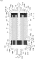
- FIG. 2 is a view schematically illustrating an example of a configuration of an internal perfusion type hollow fiber degassing module 20A provided in the chemical analyzer 2A of FIG. 1 .
- constant temperature water W1 is supplied to the inner side of the hollow fiber membrane 220, and the outer side of the hollow fiber membrane 220 is depressurized to degas the constant temperature water W1 to generate degassed constant temperature water W2.
- the hollow fiber degassing module 20A includes a housing 210 and a hollow fiber membrane 220 disposed in an internal space S1 of the housing 210.
- the housing 210 includes a cylindrical body 211 disposed such that an axial direction L is substantially horizontal, a first lid unit 212A attached to an axially lower end portion 211a of the cylindrical body 211, and a second lid unit 213A attached to an axially upper end portion 211b of the cylindrical body 211.
- the cylindrical body 211 has the internal space S1, and the hollow fiber membrane 220 is accommodated in the internal space S1.
- the cylindrical body 211 has, for example, a cylindrical shape extending in the axial direction L, and both end portions of the cylindrical body 211 are open.
- the cylindrical body 211 includes a first screw unit 214 where the cylindrical body 211 and the first lid unit 212A are screwed together, and a second screw unit 215 where the cylindrical body 211 and the second lid unit 213A are screwed together.
- the first lid unit 212A and the second lid unit 213A are fixed to the cylindrical body 211 by the first screw unit 214 and the second screw unit 215, respectively.
- the sealing unit can prevent liquid leakage that may occur between the cylindrical body 211 and the first lid unit 212A or the second lid unit 213A. Since the sealing unit does not always come into contact with liquid, the material of the sealing unit is not particularly limited within a range in which the above-described effect can be obtained. From the viewpoint of stain resistance, preferable materials for the sealing unit include polyolefin resins such as a polypropylene resin, the above-described fluororesins, or aromatic polyester resins such as a polycarbonate resin or polyethylene terephthalate.
- the first lid unit 212A includes a first wall unit 212Aa having an approximately disc shape provided perpendicularly to the axial direction L, and a second wall unit 212Ab having an approximately ring shape extending parallel to the axial direction L from the peripheral edge of the first wall unit 212Aa.
- the first lid unit 212A is fixed to the cylindrical body 211 by engaging the inner peripheral surface of the first lid unit 212A with the outer peripheral surface of the cylindrical body 211.
- the housing 210 includes a liquid supply unit (first liquid supply unit) 216A for connecting the outside of the housing 210 and an internal space S2 of the hollow fiber membrane 220 to each other, and for supplying the constant temperature water W1 from the outside of the housing 210 to the internal space S2 of the hollow fiber membrane 220.
- the liquid supply unit 216A includes a liquid supply port 216Aa that is formed, for example, on the first wall unit 212Aa of the first lid unit 212A, for supplying the constant temperature water W1 into the first lid unit 212A.
- the liquid supply port is not particularly limited, but is, for example, a circular opening in a side view formed on the central axis of the cylindrical body 211.
- the flow path 3a connected to the degassing device 3 is connected to the liquid supply unit 216A.
- the connection between the liquid supply unit 216A and the flow path 3a is not particularly limited, and may be performed by screwing or fitting.
- the second lid unit 213A includes a first wall unit 213Aa having an approximately disc shape provided perpendicularly to the axial direction L, and a second wall unit 213Ab having an approximately ring shape extending parallel to the axial direction L from the peripheral edge of the first wall unit 213Aa.
- the second lid unit 213A is fixed to the cylindrical body 211 by engaging the inner peripheral surface of the second lid unit 213A with the outer peripheral surface of the cylindrical body 211.
- the housing 210 includes a liquid discharge unit (first liquid discharge unit) 217A for connecting the internal space S2 of the hollow fiber membrane 220 and the outside of the housing 210 to each other, and for discharging the constant temperature water W2 degassed from the internal space S2 of the hollow fiber membrane 220 to the outside of the housing 210.
- the liquid discharge unit 217A includes a liquid discharge port 217Aa that is formed, for example, on the first wall unit 213Aa of the second lid unit 213A, for supplying the constant temperature water W2 to the outside.
- the liquid discharge port 217Aa is not particularly limited, but is, for example, a circular opening in a side view formed on the central axis of the cylindrical body 211.
- the flow path 3b connected to the reaction tank 5 is connected to the liquid discharge unit 217A.
- the connection between the liquid discharge unit 217A and the flow path 3b is not particularly limited, and may be performed by screwing or fitting.
- the housing 210 also includes a gas discharge unit (first gas discharge unit) 218A for connecting the internal space S1 of the housing 210 and the outside of the housing 210 to each other, and for depressurizing the internal space S1 of the housing 210.
- the gas discharge unit 218A includes a gas discharge port 218Aa that is formed, for example, in the cylindrical body 211 for discharging gas G in the internal space S1.
- the gas discharge unit 218A is disposed at the vertically upper portion of the housing 210, that is, above the vertically center position of the housing 210.
- the gas discharge unit 218A is provided on the outer peripheral portion of the housing 210.
- the amorphous fluoropolymer (hereinafter also referred to as "Teflon (registered trademark) AF”) may be an amorphous fluororesin containing a copolymer containing tetrafluoroethylene and perfluoro-2,2-dimethyl-1,3-dioxole as a comonomer.
- Teflon (registered trademark) AF an amorphous fluororesin containing a copolymer containing tetrafluoroethylene and perfluoro-2,2-dimethyl-1,3-dioxole as a comonomer.
- the polyolefin resin, the fluororesin, and the silicone resin are preferable.
- the membrane shape (shape of the side wall) of the hollow fiber membrane 220 include a porous membrane, a microporous membrane, and a homogeneous membrane (non-porous membrane) not having a porous membrane.
- Examples of the membrane form of the hollow fiber membrane 220 include a symmetrical membrane (homogeneous membrane) having a uniform chemical or physical structure of the entire membrane, and a non-symmetrical membrane (heterogeneous membrane) having a membrane chemically or physically different depending on the membrane part.
- the non-symmetrical membrane is a membrane having a non-porous dense layer and a porous material.
- the dense layer may be formed anywhere in the membrane, such as the surface layer part of the membrane or the inside of the porous membrane.
- the heterogeneous membrane includes a composite membrane having a different chemical structure and a multilayer structure membrane having a three-layer structure.
- the heterogeneous membrane using a poly(4-methylpentene-1) resin has a dense layer for blocking liquid, and thus the heterogeneous membrane is particularly preferable for degassing liquids other than water, such as constant temperature water.
- the dense layer is preferably formed on the outer surface of the hollow fiber.
- the hollow fiber membrane bundle 22 can be formed, for example, in a sheet-like article in which a plurality of hollow fiber membranes 220 are bundled in a curtain-like shape using vertical threads.
- the hollow fiber degassing module 20A can be produced by winding the sheet-like article to form the hollow fiber membrane bundle 22 and fixing both end portions of the hollow fiber membrane bundle 22 with a sealing material to be described later.
- preferable materials for the vertical threads include polyolefin resins such as a polypropylene resin, the above-described fluororesins, or aromatic polyester resins such as a polycarbonate resin or polyethylene terephthalate.
- FIG. 3(A) is a partial cross-sectional view illustrating a configuration of a first sealing unit 231A provided at an axially lower end portion 211a of the cylindrical body 211 illustrated in FIG. 2
- FIG. 3(B) is a partial cross-sectional view illustrating a configuration of a second sealing unit 232A provided at an axially upper end portion 211b of the cylindrical body 211 illustrated in FIG. 2 .
- the second sealing unit 232A is filled in the entire region of the hollow fiber membrane 220 other than the internal space S2 in a cross-section perpendicular to the axial direction L of the cylindrical body 211. That is, the second sealing unit 232A is not filled in the internal space S2 of the hollow fiber membrane 220, and is filled between the hollow fiber membranes 220 and between the hollow fiber membrane bundle 22 and the inner wall of the cylindrical body 211.
- the first sealing unit 231A and the second sealing unit 232A are not particularly limited. However, from the viewpoint of ease of production, chemical resistance, and stain resistance, the first sealing unit 231A and the second sealing unit 232A are preferably formed of, for example, a cured product of a curable resin composition containing an epoxy resin or a (meth)acrylic resin, or a polyolefin resin such as polyethylene or polypropylene.
- the first sealing unit 231A seals the axially lower end portion 211a of the cylindrical body 211 in a state where an internal space S3 of the first lid unit 212A and the internal space S2 of the hollow fiber membrane 220 communicate with each other.
- the second sealing unit 232A seals the axially upper end portion 211b of the cylindrical body 211 in a state where an internal space S4 of the second lid unit 213A and the internal space S2 of the hollow fiber membrane 220 communicate with each other.
- the internal space S3 of the first lid unit 212A and the internal space S4 of the second lid unit 213A are partitioned from the internal space S1 of the housing 210 by the first sealing unit 231A and the second sealing unit 232A, respectively, and the internal space S3 of the first lid unit 212A, the internal space S2 of the hollow fiber membrane 220, and the internal space S4 of the second lid unit 213A communicate with each other in this order.
- the constant temperature water W1 supplied from the liquid supply unit 216A to the internal space S3 of the first lid unit 212A is supplied only to the internal space S2 of the hollow fiber membrane 220, and is prevented from flowing into the internal space S1 of the housing 210. Further, since the gas is exhausted from the gas discharge port 218Aa by the vacuum pump 6, the internal space S1 of the housing 210 is depressurized, preferably to a vacuum. In other words, when the constant temperature water W1 passes through the internal space S2 of the hollow fiber membrane 220, the dissolved gas and air bubbles of the constant temperature water W1 are drawn to the outer side of the hollow fiber membrane 220, and accordingly, the degassing of the constant temperature water W1 is performed.
- the degassed constant temperature water W2 flows into the internal space S4 of the second lid unit 213A from only the internal space S2 of the hollow fiber membrane 220, and is supplied from the liquid discharge unit 217A into the reaction tank 5 of the (bio)chemical analysis unit 4A.
- the liquid contact unit of the constant temperature water W1 and W2 is mainly composed of the first lid unit 212A, the first sealing unit 231A, the hollow fiber membrane 220, the second sealing unit 232A, and the second lid unit 213A.
- the chemical resistance can be excellent and the mixing of foreign substances can be suppressed even when used for a long period in the degassing of the constant temperature water.
- the hollow fiber degassing module 20A for example, a predetermined number of hollow fiber membranes 220 are bundled together to form the hollow fiber membrane bundle 22.
- an outer support body 234 may be used to cover the hollow fiber membrane bundle 22 with the outer support body 234.
- the gas discharge port 218Aa is provided in the peripheral wall of the cylindrical body, and a screw unit and/or an O-ring groove unit is provided at both axial end portions of the cylindrical body as necessary to form the cylindrical body 211.
- the housing 210 includes the liquid discharge unit 219A that is provided at the vertically lower portion of the housing 210 for discharging the liquid generated in the housing 210, and thus water generated in the housing 210 is discharged to the outside of the housing 210 via the liquid discharge unit 219A. Accordingly, it becomes difficult for water to accumulate in the internal space S1 or the gas discharge unit 218A of the housing 210, and it is possible to maintain the original excellent degassing performance even after long periods of continuous use.
- the third lid unit 212B includes a first wall unit 212Ba having an approximately disc shape provided perpendicularly to the axial direction L, and a second wall unit 212Bb having an approximately ring shape extending parallel to the axial direction L from the peripheral edge of the first wall unit 212Ba.
- the third lid unit 212B is fixed to the cylindrical body 211 by engaging the inner peripheral surface of the third lid unit 212B with the outer peripheral surface of the cylindrical body 211.
- the housing 210 also includes a liquid discharge unit (third liquid discharge unit) 217B for connecting the internal space S1 of the housing 210 and the outside of the housing 210 to each other, and for discharging the constant temperature water W2 degassed from the internal space S1 of the housing 210 to the outside of the housing 210.
- the liquid discharge unit 217B is provided in the fourth lid unit 213B.
- the liquid discharge unit 217B includes a liquid discharge port 217Ba that is formed, for example, on the first wall unit 213Ba of the fourth lid unit 213B, for supplying the constant temperature water W2 to the outside.
- the liquid discharge port 217Ba is not particularly limited, but is, for example, a circular opening in a side view formed on the central axis of the cylindrical body 211.
- the flow path 3b connected to the reaction tank 5 is connected to the liquid discharge port 217Ba.
- the connection between the liquid discharge port 217Ba and the flow path 3b is not particularly limited, and may be performed by screwing or fitting.
- the housing 210 includes a gas discharge unit (second gas discharge unit) 218B for connecting the internal space S2 of the hollow fiber membrane 220 and the outside of the housing 210 to each other, and for depressurizing the internal space S2 of the hollow fiber membrane 220.
- the gas discharge unit 218B includes a gas discharge port 218Ba that is formed, for example, on the first wall unit 212Ba of the third lid unit 212B for discharging the gas G in the internal space S2.
- the gas discharge port 218Ba is not particularly limited, but is, for example, a circular opening in a side view formed on the central axis of the cylindrical body 211.
- the flow path 3c connected to the vacuum pump 6 is connected to the gas discharge unit 218B.
- the connection between the gas discharge unit 218B and the flow path 3c is not particularly limited, and may be performed by screwing or fitting.
- the materials for the cylindrical body 211, the third lid unit 212B, and the fourth lid unit 213B constituting the housing 210 and the material for the hollow fiber membrane 220 may be the same as those of the internal perfusion type hollow fiber degassing module 20A.
- the hollow fiber membrane bundle 22 can be formed, for example, in a sheet-like article in which a plurality of hollow fiber membranes 220 are bundled in a curtain-like shape using vertical threads.
- the hollow fiber degassing module 20B can be produced by bundling the sheet-like article into a cylindrical shape to form the hollow fiber membrane bundle and fixing both end portions of the hollow fiber membrane bundle bundled into a cylindrical shape with a sealing material.
- the material for the vertical thread the same materials as those of the internal perfusion type hollow fiber degassing module 20A can be used.
- FIG. 5(A) is a partial cross-sectional view illustrating a configuration of a third sealing unit 231B provided at one axial end portion 211c of the cylindrical body 211 illustrated in FIG. 4
- FIG. 5(B) is a partial cross-sectional view illustrating a configuration of a fourth sealing unit 232B provided at the other axial end portion 211d of the cylindrical body 211 illustrated in FIG. 4 .
- the hollow fiber degassing module 20B includes the third sealing unit 231B that seals one axial end portion 211c (refer to FIG. 4 ) of the cylindrical body 211, and the fourth sealing unit 232B that seals the other axial end portion 211d (refer to FIG. 2 ) of the cylindrical body 211.
- One longitudinal end portion 220a of the hollow fiber membrane 220 is fixed to the third sealing unit 231B, and the other longitudinal end portion 220b of the hollow fiber membrane 220 is fixed to the fourth sealing unit 232B. That is, one longitudinal end portion 22a of the hollow fiber membrane bundle 22 is fixed to the third sealing unit 231B, and the other longitudinal end portion 22b is fixed to the fourth sealing unit 232B.
- the third sealing unit 231B is filled in the entire region of the hollow fiber membrane 220 other than the internal space S2 in a cross-section perpendicular to the axial direction L of the cylindrical body 211. That is, the third sealing unit 231B is not filled in the internal space S2 of the hollow fiber membrane 220, and is filled between the hollow fiber membranes 220 and between the hollow fiber membrane bundle 22 and the inner wall of the cylindrical body 211.
- the fourth sealing unit 232B is filled in the entire region of the hollow fiber membrane 220 other than the internal space S2 in a cross-section perpendicular to the axial direction L of the cylindrical body 211. That is, the fourth sealing unit 232B is not filled in the internal space S2 of the hollow fiber membrane 220, and is filled between the hollow fiber membranes 220 and between the hollow fiber membrane bundle 22 and the inner wall of the cylindrical body 211.
- the fourth sealing unit 232B is provided with a communication port 232Ba that allows the internal space S1 of the housing 210 and the internal space S4 of the fourth lid unit 213B to communicate with each other.
- the fourth sealing unit 232B closes the other longitudinal end portion 220b of the hollow fiber membrane 220. Therefore, the internal space S2 of the hollow fiber membrane 220 does not communicate with the internal space S4 of the fourth lid unit 213B.
- the same materials as those of the internal perfusion type hollow fiber degassing module 20A can be used.
- the constant temperature water W1 supplied from the liquid supply unit 216B to the internal space S1 of the housing 210 is supplied only to the internal space S4 of the fourth lid unit 213B and prevented from flowing into the internal space S3 of the third lid unit 212B. Further, since the gas is exhausted from the gas discharge port 218Ba by the vacuum pump 6, the internal space S2 of the hollow fiber membrane 220 is depressurized, preferably to a vacuum. In other words, when the constant temperature water W1 passes through the internal space S1 of the housing 210, the dissolved gas and air bubbles of the constant temperature water W1 are drawn to the inner side of the hollow fiber membrane 220, and accordingly, the degassing of the constant temperature water W1 is performed.
- the liquid contact unit of the constant temperature water W1 and W2 is mainly composed of the third sealing unit 231B, the hollow fiber membrane 220, the fourth sealing unit 232B, and the fourth lid unit 213B.
- the chemical resistance can be excellent and the mixing of foreign substances can be suppressed even when used for a long period in the degassing of the constant temperature water.
- the hollow fiber degassing module 20B for example, a sheet-like article in which a plurality of hollow fiber membranes 220 are bundled in a curtain-like shape using vertical threads is wound around the cylindrical central pipe 233 and bundled into a cylindrical shape to form the hollow fiber membrane bundle 22.
- the outer support body 234 may be used to cover the hollow fiber membrane bundle 22 with the outer support body 234.
- the liquid supply port 216Ba is provided in the peripheral wall of the cylindrical body, and a screw unit and/or an O-ring groove unit is provided at both axial end portions of the cylindrical body as necessary to form the cylindrical body 211.
- the one axial end portion of the cylindrical body 211 and the one longitudinal end portion 22a of the hollow fiber membrane bundle 22 are fixed with a sealing material to form the third sealing unit 231B.
- the other axial end portion of the cylindrical body 211 and the other longitudinal end portion 22b of the hollow fiber membrane bundle 22 are fixed with a sealing material to form the fourth sealing unit 232B. Thereafter, only the end surface of the third sealing unit 231B or the end surfaces of the third sealing unit 231B and the fourth sealing unit 232B are cut.
- the third lid unit 212B is attached to the one axial end portion of the cylindrical body 211 provided with the third sealing unit 231B, and the fourth lid unit 213B is attached to the other axial end portion of the cylindrical body 211 provided with the fourth sealing unit 232B, respectively, to form the housing 210. Accordingly, the hollow fiber degassing module 20B including the housing 210 and the hollow fiber membrane 220 is produced.
- the housing 210 includes the liquid discharge unit 219B that is provided at the vertically lower end portion of the housing 210 for discharging the liquid generated in the housing 210, and thus water generated in the housing 210 is discharged to the outside of the housing 210 via the liquid discharge unit 219B. Accordingly, it becomes difficult for water to accumulate in the internal space S2 of the hollow fiber membrane 220 and the internal space S3 and the gas discharge unit 218B of the third lid unit 212B, and it is possible to maintain the original excellent degassing performance even after long periods of continuous use.
- the humidity of the internal space S2 of the hollow fiber membrane 220 and the internal space S3 and the gas discharge unit 218B of the third lid unit 212B can be kept low, bacteria and the like are less likely to be generated even when the internal space S2, the internal space S3, and the gas discharge unit 218B are opened after operation, and the proliferation of bacteria and the like in the internal space S2 of the hollow fiber membrane 220 and the internal space S3 and the gas discharge unit 218B of the third lid unit 212B can be suppressed.
- the constant temperature water can be degassed by supplying the constant temperature water to the outer side of the hollow fiber membrane and depressurizing the inner side of the hollow fiber membrane in the hollow fiber degassing module.
- a hollow fiber degassing module 20C includes a housing 210C and a hollow fiber membrane 220C disposed in an internal space S5 of the housing 210C.
- the housing 210C includes a cylindrical body 211C disposed such that the longitudinal direction L is substantially horizontal, and a lid unit 212C attached to one longitudinal end portion 211Ca of the cylindrical body 211C.
- the housing 210C also includes a gas discharge unit (first gas discharge unit) 218C for connecting the internal space S5 of the housing 210C and the outside of the housing 210C to each other, and for depressurizing the internal space S5 of the housing 210C.
- the gas discharge unit 218C includes a gas discharge port 218Ca that is formed, for example, in the cylindrical body 211C for discharging the gas G in the internal space S5.
- the gas discharge unit 218C is disposed at the vertically upper portion of the housing 210C, that is, above the vertically center position of the housing 210C.
- the gas discharge unit 218C is preferably provided at the vertically upper portion of the end surface of the cylindrical body 211C.
- the present configuration it becomes difficult for water to accumulate in the internal space S5 or the gas discharge unit 218C of the housing 210C, and it is possible to maintain the original excellent degassing performance even after long periods of continuous use.
- the humidity of the internal space S5 or the gas discharge unit 218C of the housing 210C can be kept low, bacteria and the like are less likely to be generated even when the internal space S5 or the gas discharge unit 218C is opened after operation, and the proliferation of bacteria and the like in the internal space S5 or the gas discharge unit 218C of the housing 210 can be suppressed.
- FIG. 7 is a block diagram illustrating a modification example of the chemical analyzer 2A illustrated in FIG. 1 .
- a chemical analyzer 2B includes a reaction disk 401, a reaction container 402, a reaction tank 403, and a circulation pump 306.
- the reaction container 402 attached to the circumference of the circular reaction disk 401 is immersed in the liquid maintained in the similarly circular reaction tank 403.
- the liquid in the reaction tank 403 is constantly circulated by the circulation pump 306 installed between a discharge pipe 404 and a supply pipe 405, and the temperature of the liquid is controlled by the on/off control of a heater 307.
- a path including the circulation pump 306 and the heater 307 between the discharge pipe 404 and the supply pipe 405 constitutes a hot water circulation path. Accordingly, the reaction solution maintained inside the reaction container 402 is maintained at an optimal temperature (for example, 37°C) for the reaction.
- the hot water circulation flow path may be provided with a cooling unit 308 for cooling the constant temperature water when the temperature of the constant temperature water in the reaction tank 403 becomes too high.
- a water supply tank 309 and a water supply pump 310 are connected to the hot water circulation flow path, and the supply of pure water from the water supply tank 309 is controlled by the water supply pump 310 and a water supply valve 311. Further, a waste liquid valve 312 is provided in the hot water circulation flow path, and the constant temperature water is discharged as waste liquid to the outside of the flow path when the high temperature water circulating in the reaction tank 403 is exchanged.
- a degassing device 313 having the hollow fiber degassing module 20A or 20B is provided, and the dissolved gas in the constant temperature water supplied into the degassing device 313 is degassed by the operation of a vacuum pump 314.
- the reaction solution obtained by mixing the sample and the reagent maintained in the reaction container 402 passes through the bundle of light emitted from the light source lamp 315, and the transmitted light is measured by the multi-wavelength photometer 316 to perform qualitative and quantitative analysis of the specific component in the sample.
- FIG. 8 is a block diagram schematically illustrating a modification example of the chemical analysis system of FIG. 1 .
- a chemical analyzer 2C includes a reaction disk 501, a reaction container 502, a reaction tank 503, a water supply tank 504, and a water supply pump 506.
- the reaction container 502 attached to the circumference of the circular reaction disk 501 is immersed in the constant temperature water maintained in the similarly circular reaction tank 503.
- the reaction tank 503 is supplied with the constant temperature water from the water supply tank 504.
- a degassing device 505 having the hollow fiber degassing module 20A or 20B is provided on the flow path between the water supply tank 504 and the reaction tank 503, and the supply of the constant temperature water is controlled by the water supply pump 506 and the water supply valve 507.
- the dissolved gas in the constant temperature water supplied into the degassing device 505 is degassed by the operation of a vacuum pump 508 and supplied from a supply pipe 517 to the reaction tank 503.
- the constant temperature water in the reaction tank 503 is constantly circulated by a circulation pump 511 installed between a discharge pipe 509 and a supply pipe 510, and the temperature of the constant temperature water is controlled by the on/off control of a heater 512.
- a path including the circulation pump 511 and a heater 514 between the discharge pipe 509 and the supply pipe 510 constitutes a hot water circulation path. Accordingly, the reaction solution maintained inside the reaction container 502 is maintained at an optimal temperature (for example, 37°C) for the reaction.
- the hot water circulation flow path may be provided with a cooling unit 513 for cooling the constant temperature water when the temperature of the constant temperature water in the reaction tank 503 becomes too high. Further, a waste liquid valve 514 is provided in the hot water circulation flow path, and the constant temperature water is discharged as waste liquid to the outside of the flow path when the constant temperature water circulating in the reaction tank 503 is exchanged.
- the reaction solution obtained by mixing the sample and the reagent maintained in the reaction container 502 passes through the bundle of light emitted from a light source lamp 515, and the transmitted light is measured by a multi-wavelength photometer 516 to perform qualitative and quantitative analysis of the specific component in the sample.
- FIG. 9 is a block diagram schematically illustrating a modification example of the (bio)chemical analysis unit 4A illustrated in FIG. 1 .
- a (bio)chemical analysis unit 4B may include a specimen container 601, a specimen dispensing mechanism 602, a reaction container 603, a reagent container 604, and a reagent dispensing mechanism 605.
- the specimen sent from the specimen container 601 to the reaction container 603 via the specimen dispensing mechanism 602 and the reagent sent from the reagent container 604 to the reaction container 603 via the reagent dispensing mechanism 605 can be mixed and stirred.
- the reaction container 603 is kept at a constant temperature by the constant temperature water stored in a reaction tank 606.
- a degassing device (not illustrated) including the hollow fiber degassing module 20A or 20B is provided, and the supply of the constant temperature water is controlled.
Landscapes
- Chemical & Material Sciences (AREA)
- Chemical Kinetics & Catalysis (AREA)
- Engineering & Computer Science (AREA)
- Water Supply & Treatment (AREA)
- Health & Medical Sciences (AREA)
- Analytical Chemistry (AREA)
- General Health & Medical Sciences (AREA)
- Nanotechnology (AREA)
- Hematology (AREA)
- Clinical Laboratory Science (AREA)
- Life Sciences & Earth Sciences (AREA)
- Immunology (AREA)
- Pathology (AREA)
- General Physics & Mathematics (AREA)
- Biochemistry (AREA)
- Physics & Mathematics (AREA)
- Separation Using Semi-Permeable Membranes (AREA)
- Degasification And Air Bubble Elimination (AREA)
- Automatic Analysis And Handling Materials Therefor (AREA)
Abstract
Description
- The present invention relates to a chemical analyzer.
- The chemical analyzer includes a degassing module having a hollow fiber membrane, and the degassing module has a mechanism of separating only gas in the liquid from the wall surface of the hollow fiber when the liquid passes through the inner side and the outer side of the hollow fiber membrane by applying a negative pressure to the outer side or the inner side of the hollow fiber membrane. The chemical analyzer is used as a device for measuring body fluid components such as blood and urine, and is widely used in an examination room, an examination center, and the like of a hospital.
- In a conventional chemical analyzer, for the purpose of miniaturizing the entire system and preventing deterioration in performance of a degassing unit in a degassed water storage tank, there has been proposed a device which enables removal of dissolved gas in pure water by heating pure water and maintaining the temperature of the pure water taken from the outside at a temperature slightly higher than a use temperature in a degassing unit formed around a preheat tank (PLT 1). However, in this method, in order to sufficiently cope with the increase in the speed of the system, a storage tank was required to store a large amount of degassed water, which made it difficult to achieve the miniaturization of the entire system.
- In order to cope with the increase in the speed of this system, it has been proposed to use a hollow fiber degassing module having a mechanism in which a hollow fiber membrane of a silicone resin is formed, and by applying a negative pressure to the outer side of the hollow fiber membrane, only gas in the liquid is separated from the wall surface of the hollow fiber when the liquid passes through the inner side of the hollow fiber membrane (PLT 2).
-
- Patent PLT 1:
JPS63-165761A - Patent PLT 2:
WO 2020/261659 - In recent years, amidst the changing environment surrounding healthcare, there is a strong demand for chemical analyzers to provide high-quality data, support rapid examination, and improve examination efficiency. However, there is a problem in that air bubbles in the reverse osmosis (RO) water used in the analysis reduce measurement accuracy.
- To solve this problem, a method of removing dissolved gas in the RO water is effective. Further, as a method in which the removal of dissolved gas can be efficiently performed, there is a method in which the hollow fiber degassing module is incorporated into the chemical analyzer to perform continuous degassing. The performance conditions for the hollow fiber degassing module to be incorporated into the device are as follows: (1) a predetermined degassing performance, (2) a size (small size) mountable on the device, (3) a low pressure loss, and (4) a long life.
- However, in the case of the hollow fiber degassing module as described above, since the hollow fiber degassing module is continuously used for a long period of time when installed in the analyzer, volatilized water may accumulate in the vacuum portion or the vacuum path inside the module, and the degassing performance may be lowered. In addition, since the vacuum path is opened periodically, bacteria proliferate and cause deterioration of performance.
- An object of the present invention is to provide a chemical analyzer equipped with a hollow fiber degassing module that is compact with low pressure loss, can maintain the original excellent degassing performance even after long periods of continuous use, and can also suppress the proliferation of bacteria and the like.
- According to a first aspect of the present invention, there is provided a chemical analyzer for performing chemical analysis or biochemical analysis of a specimen, including: a degassing unit including a constant temperature tank for maintaining a temperature of a container containing a specimen, and a hollow fiber degassing module for removing dissolved gas contained in constant temperature water in the constant temperature tank, in which the hollow fiber degassing module includes a housing and a hollow fiber membrane disposed in an internal space of the housing, and the housing includes a first liquid supply unit for connecting an outside of the housing and an internal space of the hollow fiber membrane to each other, and for supplying the constant temperature water from the outside of the housing to the inside of the hollow fiber membrane, a first liquid discharge unit for connecting the internal space of the hollow fiber membrane and the outside of the housing to each other, and for discharging the constant temperature water degassed from the internal space of the hollow fiber membrane to the outside of the housing, at least one first gas discharge unit for connecting the internal space of the housing and the outside of the housing to each other, and for depressurizing the internal space of the housing, and a second liquid discharge unit that is provided at a vertically lower end portion of the housing for discharging a liquid generated in the housing.
- The housing may include a cylindrical body disposed such that an axial direction is substantially vertical, a first lid unit attached to an axially lower end portion of the cylindrical body, and a second lid unit attached to an axially upper end portion of the cylindrical body, the first liquid supply unit may be provided in the first lid unit, and the first liquid discharge unit may be provided in the second lid unit, and the second liquid discharge unit may be provided at an outer peripheral portion of the cylindrical body.
- Further, the cylindrical body may have a cylindrical shape disposed such that the axial direction is parallel to a vertical direction, and the second liquid discharge unit may be provided in a peripheral wall of the cylindrical body.
- Furthermore, the cylindrical body may include a first screw unit where the cylindrical body and the first lid unit are screwed together, and a second screw unit where the cylindrical body and the second lid unit are screwed together.
- The hollow fiber degassing module may include a first sealing unit that seals the axially lower end portion of the cylindrical body and a second sealing unit that seals the axially upper end portion of the cylindrical body, and one longitudinal end portion of the hollow fiber membrane may be fixed to the first sealing unit, and the other longitudinal end portion of the hollow fiber membrane may be fixed to the second sealing unit.
- According to a second aspect of the present invention, there is provided a chemical analyzer for performing chemical analysis or biochemical analysis of a specimen, including: a degassing unit including a constant temperature tank for maintaining a temperature of a container containing a specimen, and a hollow fiber degassing module for removing dissolved gas contained in constant temperature water in the constant temperature tank, in which the hollow fiber degassing module includes a housing and a hollow fiber membrane disposed in an internal space of the housing, and the housing includes a second liquid supply unit for connecting an outside of the housing and an internal space of the housing to each other, and for supplying the constant temperature water from the outside of the housing to the internal space of the housing, a third liquid discharge unit for connecting the internal space of the housing and the outside of the housing to each other, and for discharging the constant temperature water degassed from the internal space of the housing to the outside of the housing, at least one second gas discharge unit for connecting the internal space of the hollow fiber membrane and the outside of the housing to each other, and for depressurizing the internal space of the hollow fiber membrane, and a fourth liquid discharge unit that is provided at a vertically lower end portion of the housing for discharging a liquid generated in the housing.
- The housing may include a cylindrical body disposed such that an axial direction is substantially horizontal, a third lid unit attached to one axial end portion of the cylindrical body, and a fourth lid unit attached to the other axial end portion of the cylindrical body, the second liquid supply unit may be provided in the cylindrical body, and the third liquid discharge unit may be provided in the fourth lid unit, and the fourth liquid discharge unit may be provided in the third lid unit.
- The cylindrical body may include a third screw unit where the cylindrical body and the third lid unit are screwed together, and a fourth screw unit where the cylindrical body and the fourth lid unit are screwed together.
- The hollow fiber degassing module may include a third sealing unit that seals the one axial end portion of the cylindrical body and a fourth sealing unit that seals the other axial end portion of the cylindrical body, and one longitudinal end portion of the hollow fiber membrane may be fixed to the third sealing unit, and the other longitudinal end portion of the hollow fiber membrane may be fixed to the fourth sealing unit.
- According to the present invention, it is possible to provide a chemical analyzer equipped with a hollow fiber degassing module that is compact with low pressure loss, can maintain the original excellent degassing performance even after long periods of continuous use, and can also suppress the proliferation of bacteria and the like.
-
-
FIG. 1 is a view schematically illustrating an example of a configuration of a chemical analysis system including a chemical analyzer according to an embodiment of the present invention. -
FIG. 2 is a view schematically illustrating an example of a configuration of an internal perfusion type hollow fiber degassing module provided in the chemical analyzer ofFIG. 1 . -
FIG. 3(A) is a partial cross-sectional view illustrating a configuration of a first sealing unit provided at an axially lower end portion of a cylindrical body illustrated inFIG. 2 , andFIG. 3(B) is a partial cross-sectional view illustrating a configuration of a second sealing unit provided at an axially upper end portion of the cylindrical body illustrated inFIG. 2 . -
FIG. 4 is a view illustrating an external perfusion type hollow fiber degassing module provided in the degassing device ofFIG. 1 . -
FIG. 5(A) is a partial cross-sectional view illustrating a configuration of a third sealing unit provided at the axially lower end portion of the cylindrical body illustrated inFIG. 2 , andFIG. 5(B) is a partial cross-sectional view illustrating a configuration of a fourth sealing unit provided at the axially upper end portion of the cylindrical body illustrated inFIG. 2 . -
FIG. 6 is a view illustrating a modification example of the internal perfusion type hollow fiber degassing module ofFIG. 2 . -
FIG. 7 is a block diagram schematically illustrating a modification example of the chemical analyzer illustrated inFIG. 1 . -
FIG. 8 is a block diagram schematically illustrating a modification example of the chemical analysis system ofFIG. 1 . -
FIG. 9 is a block diagram schematically illustrating a modification example of a (bio)chemical analysis unit illustrated inFIG. 1 . - Embodiments of the present invention will be described below. The present invention is not limited to the following embodiments.
-
FIG. 1 is a view schematically illustrating an example of a configuration of a chemical analysis system including a chemical analyzer according to an embodiment of the present invention. - As illustrated in
FIG. 1 , the chemical analysis system includes a purewater supply device 1A and achemical analyzer 2A. In thechemical analyzer 2A, a degassing device (degassing unit) 3 for degassing the constant temperature water supplied from the purewater supply device 1A and areaction tank 5 in a (bio)chemical analysis unit 4A are disposed. The purewater supply device 1A and thedegassing device 3 are connected to each other by aflow path 3a, and thedegassing device 3 and thereaction tank 5 are connected to each other by aflow path 3b. - The
degassing device 3 and avacuum pump 6 are also connected to each other by aflow path 3c. Theflow path 3c is configured with, for example, an intake pipe. The dissolved oxygen and air bubbles of the pure water supplied from the purewater supply device 1A to thedegassing device 3 are removed by the operation of the vacuum pump. In the present embodiment, the pure water degassed by thedegassing device 3 is supplied to the reaction tank (constant temperature tank) 5 via theflow path 3b. As will be described later, thedegassing device 3 and thereaction tank 5 form a circulation path, and the pure water degassed by thedegassing device 3 may be supplied to the circulation path. - The
degassing device 3 includes a hollowfiber degassing module 20A. The hollowfiber degassing module 20A has a hollowfiber membrane bundle 22 in which a plurality ofhollow fiber membranes 220 are bundled in a curtain-like shape using vertical threads (refer toFIGS. 3(A) and 3(B) ). Hereinafter, for convenience of description, the hollowfiber membrane bundle 22 may be referred to as a "hollow fiber membrane 220". Details of the hollow fiber membranes will be described later. - The
chemical analyzer 2A performs chemical analysis or biochemical analysis (hereinafter, "chemical analysis or biochemical analysis" is also referred to as "(bio)chemical analysis") of the specimen. The chemical analyzer 2Ais configured to separate only the gas in the liquid from the liquid through the wall surface of the hollow fiber when the liquid passes through the inner side or the outer side of the hollow fiber membrane by depressurizing the outer side or the inner side of the hollow fiber membrane. -
FIG. 2 is a view schematically illustrating an example of a configuration of an internal perfusion type hollowfiber degassing module 20A provided in thechemical analyzer 2A ofFIG. 1 . In the internal perfusion type hollowfiber degassing module 20A, constant temperature water W1 is supplied to the inner side of thehollow fiber membrane 220, and the outer side of thehollow fiber membrane 220 is depressurized to degas the constant temperature water W1 to generate degassed constant temperature water W2. - The hollow
fiber degassing module 20A includes ahousing 210 and ahollow fiber membrane 220 disposed in an internal space S1 of thehousing 210. Thehousing 210 includes acylindrical body 211 disposed such that an axial direction L is substantially horizontal, afirst lid unit 212A attached to an axiallylower end portion 211a of thecylindrical body 211, and asecond lid unit 213A attached to an axiallyupper end portion 211b of thecylindrical body 211. - The
cylindrical body 211 has the internal space S1, and thehollow fiber membrane 220 is accommodated in the internal space S1. Thecylindrical body 211 has, for example, a cylindrical shape extending in the axial direction L, and both end portions of thecylindrical body 211 are open. In the present embodiment, thecylindrical body 211 includes afirst screw unit 214 where thecylindrical body 211 and thefirst lid unit 212A are screwed together, and asecond screw unit 215 where thecylindrical body 211 and thesecond lid unit 213A are screwed together. Thefirst lid unit 212A and thesecond lid unit 213A are fixed to thecylindrical body 211 by thefirst screw unit 214 and thesecond screw unit 215, respectively. - The attachment of the
first lid unit 212A and thesecond lid unit 213A to thecylindrical body 211 is not limited to screwing, and can be performed by fitting, bonding, welding, or the like. Either or both of thefirst lid unit 212A and thesecond lid unit 213A may be detachably attached to thecylindrical body 211. A sealing unit (not illustrated) such as an O-ring may be provided at the attachment unit of thefirst lid unit 212A and thesecond lid unit 213A with respect to thecylindrical body 211. When the sealing unit is formed of an O-ring, it is preferable that the O-ring be disposed in an annular groove unit or the like formed at the axiallylower end portion 211a or the axiallyupper end portion 211b of thecylindrical body 211. The sealing unit can prevent liquid leakage that may occur between thecylindrical body 211 and thefirst lid unit 212A or thesecond lid unit 213A. Since the sealing unit does not always come into contact with liquid, the material of the sealing unit is not particularly limited within a range in which the above-described effect can be obtained. From the viewpoint of stain resistance, preferable materials for the sealing unit include polyolefin resins such as a polypropylene resin, the above-described fluororesins, or aromatic polyester resins such as a polycarbonate resin or polyethylene terephthalate. - The
first lid unit 212A includes a first wall unit 212Aa having an approximately disc shape provided perpendicularly to the axial direction L, and a second wall unit 212Ab having an approximately ring shape extending parallel to the axial direction L from the peripheral edge of the first wall unit 212Aa. Thefirst lid unit 212A is fixed to thecylindrical body 211 by engaging the inner peripheral surface of thefirst lid unit 212A with the outer peripheral surface of thecylindrical body 211. - The
housing 210 includes a liquid supply unit (first liquid supply unit) 216A for connecting the outside of thehousing 210 and an internal space S2 of thehollow fiber membrane 220 to each other, and for supplying the constant temperature water W1 from the outside of thehousing 210 to the internal space S2 of thehollow fiber membrane 220. Theliquid supply unit 216A includes a liquid supply port 216Aa that is formed, for example, on the first wall unit 212Aa of thefirst lid unit 212A, for supplying the constant temperature water W1 into thefirst lid unit 212A. The liquid supply port is not particularly limited, but is, for example, a circular opening in a side view formed on the central axis of thecylindrical body 211. Theflow path 3a connected to thedegassing device 3 is connected to theliquid supply unit 216A. The connection between theliquid supply unit 216A and theflow path 3a is not particularly limited, and may be performed by screwing or fitting. - The
second lid unit 213A includes a first wall unit 213Aa having an approximately disc shape provided perpendicularly to the axial direction L, and a second wall unit 213Ab having an approximately ring shape extending parallel to the axial direction L from the peripheral edge of the first wall unit 213Aa. Thesecond lid unit 213A is fixed to thecylindrical body 211 by engaging the inner peripheral surface of thesecond lid unit 213A with the outer peripheral surface of thecylindrical body 211. - The
housing 210 includes a liquid discharge unit (first liquid discharge unit) 217A for connecting the internal space S2 of thehollow fiber membrane 220 and the outside of thehousing 210 to each other, and for discharging the constant temperature water W2 degassed from the internal space S2 of thehollow fiber membrane 220 to the outside of thehousing 210. Theliquid discharge unit 217A includes a liquid discharge port 217Aa that is formed, for example, on the first wall unit 213Aa of thesecond lid unit 213A, for supplying the constant temperature water W2 to the outside. The liquid discharge port 217Aa is not particularly limited, but is, for example, a circular opening in a side view formed on the central axis of thecylindrical body 211. Theflow path 3b connected to thereaction tank 5 is connected to theliquid discharge unit 217A. The connection between theliquid discharge unit 217A and theflow path 3b is not particularly limited, and may be performed by screwing or fitting. - The
housing 210 also includes a gas discharge unit (first gas discharge unit) 218A for connecting the internal space S1 of thehousing 210 and the outside of thehousing 210 to each other, and for depressurizing the internal space S1 of thehousing 210. Thegas discharge unit 218A includes a gas discharge port 218Aa that is formed, for example, in thecylindrical body 211 for discharging gas G in the internal space S1. In the present embodiment, thegas discharge unit 218A is disposed at the vertically upper portion of thehousing 210, that is, above the vertically center position of thehousing 210. Thegas discharge unit 218A is provided on the outer peripheral portion of thehousing 210. When thecylindrical body 211 has a cylindrical shape disposed such that the axial direction L is parallel to the vertical direction, thegas discharge unit 218A is preferably provided in the peripheral wall of thecylindrical body 211. Thus, moisture generated in thecylindrical body 211 is discharged to the outside from the outer periphery of thecylindrical body 211 via thegas discharge unit 218A. Theflow path 3c connected to thevacuum pump 6 is connected to thegas discharge unit 218A. The connection between thegas discharge unit 218A and theflow path 3c is not particularly limited, and may be performed by screwing or fitting. - In the present embodiment, the
housing 210 includes onegas discharge unit housing 210 may have a plurality ofgas discharge units housing 210, the dimension of the gas discharge port 218Aa, the capacity of the vacuum pump, and the like. - The
housing 210 further includes a liquid discharge unit (second liquid discharge unit) 219A that is provided at the vertically lower end portion of thehousing 210 for discharging the liquid generated in thehousing 210. Theliquid discharge unit 219A includes a liquid discharge port 219Aa that is formed, for example, in thecylindrical body 211 for discharging a liquid W3 in the internal space S1. Theliquid discharge unit 219A is a drain through which water liquefied in the internal space S1 of thehousing 210 is discharged to the outside, and has a different purpose and function from thegas discharge unit 218A that discharges gas containing moisture. Theliquid discharge unit 219A is provided on the outer peripheral portion of thehousing 210. When thecylindrical body 211 has a cylindrical shape disposed such that the axial direction L is parallel to the vertical direction, theliquid discharge unit 219A is preferably provided in the peripheral wall of thecylindrical body 211. Accordingly, water generated in the internal space S1 of thehousing 210 is discharged to the outside of thehousing 210 via theliquid discharge unit 219A, and water can be prevented from accumulating in thehousing 210. In the present embodiment, oneliquid discharge unit 219A is provided, but a plurality ofliquid discharge units 219A may be provided. - The materials used for the
cylindrical body 211, thefirst lid unit 212A, and thesecond lid unit 213A, which constitute thehousing 210, are not particularly limited. However, from the viewpoint of ease of production, chemical resistance, and stain resistance, polyolefin resins such as a polypropylene resin, and aromatic polyester resins such as a polycarbonate resin or polyethylene terephthalate are preferred. In this case, thecylindrical body 211, thefirst lid unit 212A, and thesecond lid unit 213A can be produced by injection molding. - The
hollow fiber membrane 220 is a hollow fiber-shaped membrane that allows gases to permeate but does not allow liquids to permeate. The material, membrane shape, membrane form, and the like of thehollow fiber membrane 220 are not particularly limited. From the viewpoint of ease of production, chemical resistance, and stain resistance, the material of thehollow fiber membrane 220 include, for example, polyolefin resins such as polypropylene and poly(4-methylpentene-1), silicone resins, and fluororesins such as PTFE, amorphous fluoropolymers, tetrafluoroethylene-perfluoroalkyl vinyl ether copolymers (hereinafter also referred to as PFA), tetrafluoroethylene-hexafluoropropylene copolymers (hereinafter also referred to as FEP), tetrafluoroethylene-ethylene copolymers (hereinafter also referred to as ETFE), polychlorotrifluoroethylene (hereinafter also referred to as PCTFE), and polyvinylidene fluoride (hereinafter also referred to as PVDF). More specifically, the amorphous fluoropolymer (hereinafter also referred to as "Teflon (registered trademark) AF") may be an amorphous fluororesin containing a copolymer containing tetrafluoroethylene and perfluoro-2,2-dimethyl-1,3-dioxole as a comonomer. Among these, the polyolefin resin, the fluororesin, and the silicone resin are preferable. Examples of the membrane shape (shape of the side wall) of thehollow fiber membrane 220 include a porous membrane, a microporous membrane, and a homogeneous membrane (non-porous membrane) not having a porous membrane. Examples of the membrane form of thehollow fiber membrane 220 include a symmetrical membrane (homogeneous membrane) having a uniform chemical or physical structure of the entire membrane, and a non-symmetrical membrane (heterogeneous membrane) having a membrane chemically or physically different depending on the membrane part. The non-symmetrical membrane (heterogeneous membrane) is a membrane having a non-porous dense layer and a porous material. In this case, the dense layer may be formed anywhere in the membrane, such as the surface layer part of the membrane or the inside of the porous membrane. The heterogeneous membrane includes a composite membrane having a different chemical structure and a multilayer structure membrane having a three-layer structure. - In particular, the heterogeneous membrane using a poly(4-methylpentene-1) resin has a dense layer for blocking liquid, and thus the heterogeneous membrane is particularly preferable for degassing liquids other than water, such as constant temperature water. In addition, in the case of the hollow fiber used for the external perfusion type, the dense layer is preferably formed on the outer surface of the hollow fiber.
- The hollow
fiber membrane bundle 22 can be formed, for example, in a sheet-like article in which a plurality ofhollow fiber membranes 220 are bundled in a curtain-like shape using vertical threads. In this case, for example, the hollowfiber degassing module 20A can be produced by winding the sheet-like article to form the hollowfiber membrane bundle 22 and fixing both end portions of the hollowfiber membrane bundle 22 with a sealing material to be described later. From the viewpoint of ease of production, chemical resistance, and stain resistance, preferable materials for the vertical threads include polyolefin resins such as a polypropylene resin, the above-described fluororesins, or aromatic polyester resins such as a polycarbonate resin or polyethylene terephthalate. -
FIG. 3(A) is a partial cross-sectional view illustrating a configuration of afirst sealing unit 231A provided at an axiallylower end portion 211a of thecylindrical body 211 illustrated inFIG. 2 , andFIG. 3(B) is a partial cross-sectional view illustrating a configuration of asecond sealing unit 232A provided at an axiallyupper end portion 211b of thecylindrical body 211 illustrated inFIG. 2 . - As illustrated in
FIGS. 3(A) and 3(B) , the hollowfiber degassing module 20A includes the first sealing unit 23 1Athat seals the axiallylower end portion 211a (refer toFIG. 2 ) of thecylindrical body 211, and thesecond sealing unit 232A that seals the axiallyupper end portion 211b (refer toFIG. 2 ) of thecylindrical body 211. Onelongitudinal end portion 220a of thehollow fiber membrane 220 is fixed to thefirst sealing unit 231A, and the otherlongitudinal end portion 220b of thehollow fiber membrane 220 is fixed to thesecond sealing unit 232A. That is, onelongitudinal end portion 22a of the hollowfiber membrane bundle 22 is fixed to thefirst sealing unit 231A, and the otherlongitudinal end portion 22b is fixed to thesecond sealing unit 232A. - The
first sealing unit 231A is filled in the entire region of thehollow fiber membrane 220 other than the internal space S2 in a cross-section perpendicular to the axial direction L of thecylindrical body 211. That is, thefirst sealing unit 231A is not filled in the internal space S2 of thehollow fiber membrane 220, and is filled between thehollow fiber membranes 220 and between the hollowfiber membrane bundle 22 and the inner wall of thecylindrical body 211. - Similar to the
first sealing unit 231A, thesecond sealing unit 232A is filled in the entire region of thehollow fiber membrane 220 other than the internal space S2 in a cross-section perpendicular to the axial direction L of thecylindrical body 211. That is, thesecond sealing unit 232A is not filled in the internal space S2 of thehollow fiber membrane 220, and is filled between thehollow fiber membranes 220 and between the hollowfiber membrane bundle 22 and the inner wall of thecylindrical body 211. - The
first sealing unit 231A and thesecond sealing unit 232A are not particularly limited. However, from the viewpoint of ease of production, chemical resistance, and stain resistance, thefirst sealing unit 231A and thesecond sealing unit 232A are preferably formed of, for example, a cured product of a curable resin composition containing an epoxy resin or a (meth)acrylic resin, or a polyolefin resin such as polyethylene or polypropylene. - In the present embodiment, the
first sealing unit 231A seals the axiallylower end portion 211a of thecylindrical body 211 in a state where an internal space S3 of thefirst lid unit 212A and the internal space S2 of thehollow fiber membrane 220 communicate with each other. Thesecond sealing unit 232A seals the axiallyupper end portion 211b of thecylindrical body 211 in a state where an internal space S4 of thesecond lid unit 213A and the internal space S2 of thehollow fiber membrane 220 communicate with each other. That is, the internal space S3 of thefirst lid unit 212A and the internal space S4 of thesecond lid unit 213A are partitioned from the internal space S1 of thehousing 210 by thefirst sealing unit 231A and thesecond sealing unit 232A, respectively, and the internal space S3 of thefirst lid unit 212A, the internal space S2 of thehollow fiber membrane 220, and the internal space S4 of thesecond lid unit 213A communicate with each other in this order. - Therefore, the constant temperature water W1 supplied from the
liquid supply unit 216A to the internal space S3 of thefirst lid unit 212A is supplied only to the internal space S2 of thehollow fiber membrane 220, and is prevented from flowing into the internal space S1 of thehousing 210. Further, since the gas is exhausted from the gas discharge port 218Aa by thevacuum pump 6, the internal space S1 of thehousing 210 is depressurized, preferably to a vacuum. In other words, when the constant temperature water W1 passes through the internal space S2 of thehollow fiber membrane 220, the dissolved gas and air bubbles of the constant temperature water W1 are drawn to the outer side of thehollow fiber membrane 220, and accordingly, the degassing of the constant temperature water W1 is performed. - The degassed constant temperature water W2 flows into the internal space S4 of the
second lid unit 213A from only the internal space S2 of thehollow fiber membrane 220, and is supplied from theliquid discharge unit 217A into thereaction tank 5 of the (bio)chemical analysis unit 4A. - As described above, in the hollow
fiber degassing module 20A, the liquid contact unit of the constant temperature water W1 and W2 is mainly composed of thefirst lid unit 212A, thefirst sealing unit 231A, thehollow fiber membrane 220, thesecond sealing unit 232A, and thesecond lid unit 213A. By using the above-described preferable material for each unit, which constitute the liquid contact unit, the chemical resistance can be excellent and the mixing of foreign substances can be suppressed even when used for a long period in the degassing of the constant temperature water. - In the production method of the hollow
fiber degassing module 20A, for example, a predetermined number ofhollow fiber membranes 220 are bundled together to form the hollowfiber membrane bundle 22. At this time, anouter support body 234 may be used to cover the hollowfiber membrane bundle 22 with theouter support body 234. Further, the gas discharge port 218Aa is provided in the peripheral wall of the cylindrical body, and a screw unit and/or an O-ring groove unit is provided at both axial end portions of the cylindrical body as necessary to form thecylindrical body 211. In a state where the hollowfiber membrane bundle 22 is accommodated in thecylindrical body 211, one axial end portion of thecylindrical body 211 and onelongitudinal end portion 22a of the hollowfiber membrane bundle 22 are fixed with a sealing material to form thefirst sealing unit 231A, and further, the other axial end portion of thecylindrical body 211 and the otherlongitudinal end portion 22b of the hollowfiber membrane bundle 22 are fixed with a sealing material to form thesecond sealing unit 232A. Thereafter, the end surfaces of thefirst sealing unit 231A and thesecond sealing unit 232A are cut. Finally, thefirst lid unit 212A is attached to the one axial end portion of thecylindrical body 211, and thesecond lid unit 213A is attached to the other axial end portion of thecylindrical body 211, respectively, to form thehousing 210. Accordingly, the hollowfiber degassing module 20A including thehousing 210 and thehollow fiber membrane 220 is produced. - As described above, according to the present embodiment, in the hollow
fiber degassing module 20A, thehousing 210 includes theliquid discharge unit 219A that is provided at the vertically lower portion of thehousing 210 for discharging the liquid generated in thehousing 210, and thus water generated in thehousing 210 is discharged to the outside of thehousing 210 via theliquid discharge unit 219A. Accordingly, it becomes difficult for water to accumulate in the internal space S1 or thegas discharge unit 218A of thehousing 210, and it is possible to maintain the original excellent degassing performance even after long periods of continuous use. In addition, since the humidity of the internal space S1 or thegas discharge unit 218A of thehousing 210 can be kept low, bacteria and the like are less likely to be generated even when the internal space S1 or thegas discharge unit 218A are opened after operation, and the proliferation of bacteria and the like in the internal space S1 or thegas discharge unit 218A of thehousing 210 can be suppressed. - In a degassing method for removing the dissolved gas contained in the constant temperature water in the constant temperature tank in the chemical analyzer according to the present embodiment, the constant temperature water can be degassed by supplying the constant temperature water to the inner side of the hollow fiber membrane and depressurizing the outer side of the hollow fiber membrane in the hollow fiber degassing module.
-
FIG. 4 is a view illustrating an external perfusion type hollow fiber degassing module provided in thedegassing device 3 ofFIG. 1 . Thechemical analyzer 2A may include an external reflux type hollowfiber degassing module 20B instead of the internal reflux type hollow fiber degassing module. In the hollowfiber degassing module 20B, the constant temperature water W1 is supplied to the outer side of thehollow fiber membrane 220, and the inner side of thehollow fiber membrane 220 is depressurized to degas the constant temperature water W1 to generate the degassed constant temperature water W2. - The hollow
fiber degassing module 20B includes thehousing 210 and thehollow fiber membrane 220 disposed in the internal space S1 of thehousing 210. Thehousing 210 includes acylindrical body 211 disposed such that the axial direction L is substantially horizontal, athird lid unit 212B attached to oneaxial end portion 211c of thecylindrical body 211, and afourth lid unit 213B attached to the otheraxial end portion 211d of thecylindrical body 211. - The
cylindrical body 211 has the internal space S1, and thehollow fiber membrane 220 is accommodated in the internal space S1. Thecylindrical body 211 has, for example, a cylindrical shape extending in the axial direction L, and both end portions of thecylindrical body 211 are open. In the present embodiment, thecylindrical body 211 includes thefirst screw unit 214 where thecylindrical body 211 and thethird lid unit 212B are screwed together, and thesecond screw unit 215 where thecylindrical body 211 and thefourth lid unit 213B are screwed together. Thethird lid unit 212B and thefourth lid unit 213B are fixed to thecylindrical body 211 by thefirst screw unit 214 and thesecond screw unit 215, respectively. - The attachment of the
third lid unit 212B and thefourth lid unit 213B to thecylindrical body 211 is not limited to screwing, and can be performed by fitting, bonding, welding, or the like. Either or both of thethird lid unit 212B and thefourth lid unit 213B may be detachably attached to thecylindrical body 211. A sealing unit (not illustrated) such as an O-ring may be provided at the attachment unit of thethird lid unit 212B and thefourth lid unit 213B with respect to thecylindrical body 211. When the sealing unit is formed of an O-ring, it is preferable that the O-ring be disposed in an annular groove unit or the like formed at the oneaxial end portion 211c or the otheraxial end portion 211d of thecylindrical body 211. The sealing unit can prevent liquid leakage that may occur between thecylindrical body 211 and thethird lid unit 212B or thefourth lid unit 213B. Since the sealing unit does not always come into contact with liquid, the material of the sealing unit is not particularly limited within a range in which the above-described effect can be obtained. From the viewpoint of stain resistance, preferable materials for the sealing unit include polyolefin resins such as a polypropylene resin, the above-described fluororesins, or aromatic polyester resins such as a polycarbonate resin or polyethylene terephthalate. - The
third lid unit 212B includes a first wall unit 212Ba having an approximately disc shape provided perpendicularly to the axial direction L, and a second wall unit 212Bb having an approximately ring shape extending parallel to the axial direction L from the peripheral edge of the first wall unit 212Ba. Thethird lid unit 212B is fixed to thecylindrical body 211 by engaging the inner peripheral surface of thethird lid unit 212B with the outer peripheral surface of thecylindrical body 211. - The
fourth lid unit 213B includes a first wall unit 213Ba having an approximately disc shape provided perpendicularly to the axial direction L, and a second wall unit 213Bb having an approximately ring shape extending parallel to the axial direction L from the peripheral edge of the first wall unit 213Ba. Thefourth lid unit 213B is fixed to thecylindrical body 211 by engaging the inner peripheral surface of thefourth lid unit 213B with the outer peripheral surface of thecylindrical body 211. - The
housing 210 includes a liquid supply unit (second liquid supply unit) 216B for connecting the outside of thehousing 210 and the internal space S1 of thehousing 210 to each other, and for supplying the constant temperature water W1 from the outside of thehousing 210 to the internal space S1 of thehousing 210. In the present embodiment, theliquid supply unit 216B is provided in thecylindrical body 211. Theliquid supply unit 216B includes a liquid supply port 216Ba that is formed, for example, in thecylindrical body 211, for supplying the constant temperature water W1 into thecylindrical body 211. The liquid supply port is not particularly limited, but is a circular opening in a side view formed at the vertically lower end portion of thecylindrical body 211. Theflow path 3a connected to thedegassing device 3 is connected to the liquid supply port 216Ba. The connection between the liquid supply port 216Ba and theflow path 3a is not particularly limited, and may be performed by screwing or fitting. - The
housing 210 also includes a liquid discharge unit (third liquid discharge unit) 217B for connecting the internal space S1 of thehousing 210 and the outside of thehousing 210 to each other, and for discharging the constant temperature water W2 degassed from the internal space S1 of thehousing 210 to the outside of thehousing 210. In the present embodiment, theliquid discharge unit 217B is provided in thefourth lid unit 213B. Theliquid discharge unit 217B includes a liquid discharge port 217Ba that is formed, for example, on the first wall unit 213Ba of thefourth lid unit 213B, for supplying the constant temperature water W2 to the outside. The liquid discharge port 217Ba is not particularly limited, but is, for example, a circular opening in a side view formed on the central axis of thecylindrical body 211. Theflow path 3b connected to thereaction tank 5 is connected to the liquid discharge port 217Ba. The connection between the liquid discharge port 217Ba and theflow path 3b is not particularly limited, and may be performed by screwing or fitting. - Furthermore, the
housing 210 includes a gas discharge unit (second gas discharge unit) 218B for connecting the internal space S2 of thehollow fiber membrane 220 and the outside of thehousing 210 to each other, and for depressurizing the internal space S2 of thehollow fiber membrane 220. Thegas discharge unit 218B includes a gas discharge port 218Ba that is formed, for example, on the first wall unit 212Ba of thethird lid unit 212B for discharging the gas G in the internal space S2. The gas discharge port 218Ba is not particularly limited, but is, for example, a circular opening in a side view formed on the central axis of thecylindrical body 211. As a result, moisture generated in the internal space S2 of thehollow fiber membrane 220 and/or in the internal space S3 of thethird lid unit 212B is discharged to the outside from the one axial end portion of thehollow fiber membrane 220 via thegas discharge unit 218B. Theflow path 3c connected to thevacuum pump 6 is connected to thegas discharge unit 218B. The connection between thegas discharge unit 218B and theflow path 3c is not particularly limited, and may be performed by screwing or fitting. - The
housing 210 further includes a liquid discharge unit (fourth liquid discharge unit) 219B that is provided at the vertically lower end portion of thehousing 210 for discharging the liquid generated in thehousing 210. Theliquid discharge unit 219B includes a liquid discharge port 219Ba that is formed, for example, in thecylindrical body 211 for discharging the liquid W3 in the internal space S1. Theliquid discharge unit 219B is a drain through which water liquefied in the internal space S2 of thehollow fiber membrane 220 and/or the internal space S3 of thethird lid unit 212B is discharged to the outside, and has a different purpose and function from thegas discharge unit 218B that discharges gas containing moisture. Theliquid discharge unit 219B is provided on the outer peripheral portion of thehousing 210. When thecylindrical body 211 has a cylindrical shape disposed such that the axial direction L is parallel to the vertical direction, theliquid discharge unit 219B is preferably provided in the peripheral wall of thecylindrical body 211. Accordingly, moisture generated in the internal space S2 of thehollow fiber membrane 220 and/or the internal space S3 of thethird lid unit 212B is discharged to the outside of thehousing 210 via theliquid discharge unit 219B, and water can be prevented from accumulating in thehousing 210. In the present embodiment, oneliquid discharge unit 219B is provided, but twoliquid discharge units - The
housing 210 also includes acentral pipe 233 disposed on the inside of thecylindrical body 211 to be parallel to the axial direction of thecylindrical body 211, and theouter support body 234 substantially coaxial with thecentral pipe 233 and disposed between thecylindrical body 211 and thecentral pipe 233. Thecentral pipe 233, theouter support body 234, and thecylindrical body 211 are arranged in this order from the center toward the outer side in the radial direction of thehousing 210. A hollowfiber membrane bundle 22 is disposed between thecentral pipe 233 and theouter support body 234. - The materials for the
cylindrical body 211, thethird lid unit 212B, and thefourth lid unit 213B constituting thehousing 210 and the material for thehollow fiber membrane 220 may be the same as those of the internal perfusion type hollowfiber degassing module 20A. - The hollow
fiber membrane bundle 22 can be formed, for example, in a sheet-like article in which a plurality ofhollow fiber membranes 220 are bundled in a curtain-like shape using vertical threads. In this case, for example, the hollowfiber degassing module 20B can be produced by bundling the sheet-like article into a cylindrical shape to form the hollow fiber membrane bundle and fixing both end portions of the hollow fiber membrane bundle bundled into a cylindrical shape with a sealing material. As the material for the vertical thread, the same materials as those of the internal perfusion type hollowfiber degassing module 20A can be used. -
FIG. 5(A) is a partial cross-sectional view illustrating a configuration of athird sealing unit 231B provided at oneaxial end portion 211c of thecylindrical body 211 illustrated inFIG. 4 , andFIG. 5(B) is a partial cross-sectional view illustrating a configuration of afourth sealing unit 232B provided at the otheraxial end portion 211d of thecylindrical body 211 illustrated inFIG. 4 . - As illustrated in
FIGS. 5(A) and 5(B) , the hollowfiber degassing module 20B includes thethird sealing unit 231B that seals oneaxial end portion 211c (refer toFIG. 4 ) of thecylindrical body 211, and thefourth sealing unit 232B that seals the otheraxial end portion 211d (refer toFIG. 2 ) of thecylindrical body 211. Onelongitudinal end portion 220a of thehollow fiber membrane 220 is fixed to thethird sealing unit 231B, and the otherlongitudinal end portion 220b of thehollow fiber membrane 220 is fixed to thefourth sealing unit 232B. That is, onelongitudinal end portion 22a of the hollowfiber membrane bundle 22 is fixed to thethird sealing unit 231B, and the otherlongitudinal end portion 22b is fixed to thefourth sealing unit 232B. - The
third sealing unit 231B is filled in the entire region of thehollow fiber membrane 220 other than the internal space S2 in a cross-section perpendicular to the axial direction L of thecylindrical body 211. That is, thethird sealing unit 231B is not filled in the internal space S2 of thehollow fiber membrane 220, and is filled between thehollow fiber membranes 220 and between the hollowfiber membrane bundle 22 and the inner wall of thecylindrical body 211. - Similar to the
third sealing unit 231B, thefourth sealing unit 232B is filled in the entire region of thehollow fiber membrane 220 other than the internal space S2 in a cross-section perpendicular to the axial direction L of thecylindrical body 211. That is, thefourth sealing unit 232B is not filled in the internal space S2 of thehollow fiber membrane 220, and is filled between thehollow fiber membranes 220 and between the hollowfiber membrane bundle 22 and the inner wall of thecylindrical body 211. Thefourth sealing unit 232B is provided with a communication port 232Ba that allows the internal space S1 of thehousing 210 and the internal space S4 of thefourth lid unit 213B to communicate with each other. Thefourth sealing unit 232B closes the otherlongitudinal end portion 220b of thehollow fiber membrane 220. Therefore, the internal space S2 of thehollow fiber membrane 220 does not communicate with the internal space S4 of thefourth lid unit 213B. - As the material of the
third sealing unit 231B and thefourth sealing unit 232B, the same materials as those of the internal perfusion type hollowfiber degassing module 20A can be used. - In the present embodiment, the
third sealing unit 231B seals the oneaxial end portion 211c of thecylindrical body 211 in a state where the internal space S3 of thethird lid unit 212B and the internal space S2 of thehollow fiber membrane 220 communicate with each other. Thefourth sealing unit 232B seals the otheraxial end portion 211d of thecylindrical body 211 in a state where the internal space S4 of thefourth lid unit 213B and the internal space S2 of thehollow fiber membrane 220 are closed. That is, the internal space S3 of thethird lid unit 212B and the internal space S1 of thehousing 210 are partitioned by thethird sealing unit 231B, the internal space S4 of thefourth lid unit 213B and the internal space S1 of thehousing 210 communicate with each other, and the internal space S3 of thethird lid unit 212B and the internal space S2 of thehollow fiber membrane 220 communicate with each other. - Therefore, the constant temperature water W1 supplied from the
liquid supply unit 216B to the internal space S1 of thehousing 210 is supplied only to the internal space S4 of thefourth lid unit 213B and prevented from flowing into the internal space S3 of thethird lid unit 212B. Further, since the gas is exhausted from the gas discharge port 218Ba by thevacuum pump 6, the internal space S2 of thehollow fiber membrane 220 is depressurized, preferably to a vacuum. In other words, when the constant temperature water W1 passes through the internal space S1 of thehousing 210, the dissolved gas and air bubbles of the constant temperature water W1 are drawn to the inner side of thehollow fiber membrane 220, and accordingly, the degassing of the constant temperature water W1 is performed. - The degassed constant temperature water W2 flows into the internal space S4 of the
fourth lid unit 213B from only the internal space S1 of thehousing 210, and is supplied from theliquid discharge unit 217B into thereaction tank 5 of the (bio)chemical analysis unit 4A. - As described above, in the hollow
fiber degassing module 20B, the liquid contact unit of the constant temperature water W1 and W2 is mainly composed of thethird sealing unit 231B, thehollow fiber membrane 220, thefourth sealing unit 232B, and thefourth lid unit 213B. By using the above-described preferable material for each unit, which constitute the liquid contact unit, the chemical resistance can be excellent and the mixing of foreign substances can be suppressed even when used for a long period in the degassing of the constant temperature water. - In the production method of the hollow
fiber degassing module 20B, for example, a sheet-like article in which a plurality ofhollow fiber membranes 220 are bundled in a curtain-like shape using vertical threads is wound around the cylindricalcentral pipe 233 and bundled into a cylindrical shape to form the hollowfiber membrane bundle 22. At this time, theouter support body 234 may be used to cover the hollowfiber membrane bundle 22 with theouter support body 234. Further, the liquid supply port 216Ba is provided in the peripheral wall of the cylindrical body, and a screw unit and/or an O-ring groove unit is provided at both axial end portions of the cylindrical body as necessary to form thecylindrical body 211. In a state where the hollowfiber membrane bundle 22 and thecentral pipe 233 are accommodated in thecylindrical body 211, the one axial end portion of thecylindrical body 211 and the onelongitudinal end portion 22a of the hollowfiber membrane bundle 22 are fixed with a sealing material to form thethird sealing unit 231B. Further, the other axial end portion of thecylindrical body 211 and the otherlongitudinal end portion 22b of the hollowfiber membrane bundle 22 are fixed with a sealing material to form thefourth sealing unit 232B. Thereafter, only the end surface of thethird sealing unit 231B or the end surfaces of thethird sealing unit 231B and thefourth sealing unit 232B are cut. Thereafter, thethird lid unit 212B is attached to the one axial end portion of thecylindrical body 211 provided with thethird sealing unit 231B, and thefourth lid unit 213B is attached to the other axial end portion of thecylindrical body 211 provided with thefourth sealing unit 232B, respectively, to form thehousing 210. Accordingly, the hollowfiber degassing module 20B including thehousing 210 and thehollow fiber membrane 220 is produced. - As described above, according to the present embodiment, in the hollow
fiber degassing module 20B, thehousing 210 includes theliquid discharge unit 219B that is provided at the vertically lower end portion of thehousing 210 for discharging the liquid generated in thehousing 210, and thus water generated in thehousing 210 is discharged to the outside of thehousing 210 via theliquid discharge unit 219B. Accordingly, it becomes difficult for water to accumulate in the internal space S2 of thehollow fiber membrane 220 and the internal space S3 and thegas discharge unit 218B of thethird lid unit 212B, and it is possible to maintain the original excellent degassing performance even after long periods of continuous use. In addition, since the humidity of the internal space S2 of thehollow fiber membrane 220 and the internal space S3 and thegas discharge unit 218B of thethird lid unit 212B can be kept low, bacteria and the like are less likely to be generated even when the internal space S2, the internal space S3, and thegas discharge unit 218B are opened after operation, and the proliferation of bacteria and the like in the internal space S2 of thehollow fiber membrane 220 and the internal space S3 and thegas discharge unit 218B of thethird lid unit 212B can be suppressed. - In a degassing method for removing the dissolved gas contained in the constant temperature water in the constant temperature tank in the chemical analyzer according to the present embodiment, the constant temperature water can be degassed by supplying the constant temperature water to the outer side of the hollow fiber membrane and depressurizing the inner side of the hollow fiber membrane in the hollow fiber degassing module.
-
FIG. 6 is a view illustrating a modification example of the hollowfiber degassing module 20A ofFIG. 2 . - As illustrated in
FIG. 6 , a hollow fiber degassing module 20C includes ahousing 210C and ahollow fiber membrane 220C disposed in an internal space S5 of thehousing 210C. Thehousing 210C includes acylindrical body 211C disposed such that the longitudinal direction L is substantially horizontal, and alid unit 212C attached to one longitudinal end portion 211Ca of thecylindrical body 211C. - The
housing 210C includes a liquid supply unit (first liquid supply unit) 216C for connecting the outside of thehousing 210C and the internal space S5 of thehollow fiber membrane 220C to each other, and for supplying the constant temperature water W1 from the outside of thehousing 210C to the inside of thehollow fiber membrane 220C. The liquid supply unit 216C includes a first connector unit 216Ca that is formed, for example, on thelid unit 212C, for supplying the constant temperature water W1 into thefirst lid unit 212A. One longitudinal end portion 220Ca of thehollow fiber membrane 220C is fixed to the first connector unit 216Ca. - The
housing 210C includes a liquid discharge unit (first liquid discharge unit) 217C for connecting an internal space S6 of thehollow fiber membrane 220C and the outside of thehousing 210C to each other, and for discharging the constant temperature water W2 degassed from the internal space S5 of thehollow fiber membrane 220C to the outside of thehousing 210C. Theliquid discharge unit 217C includes a second connector unit 217Ca that is formed, for example, on thelid unit 212C, for supplying the constant temperature water W1 into thefirst lid unit 212A. The other longitudinal end portion 220Cb of thehollow fiber membrane 220C is fixed to the second connector unit 217Ca. Thehousing 210C may include anouter support body 234C covering a hollow fiber membrane bundle 22C composed of thehollow fiber membranes 220C. - The
housing 210C also includes a gas discharge unit (first gas discharge unit) 218C for connecting the internal space S5 of thehousing 210C and the outside of thehousing 210C to each other, and for depressurizing the internal space S5 of thehousing 210C. Thegas discharge unit 218C includes a gas discharge port 218Ca that is formed, for example, in thecylindrical body 211C for discharging the gas G in the internal space S5. Thegas discharge unit 218C is disposed at the vertically upper portion of thehousing 210C, that is, above the vertically center position of thehousing 210C. When thecylindrical body 211C has a cylindrical shape disposed such that the longitudinal direction L is parallel to the horizontal direction, thegas discharge unit 218C is preferably provided at the vertically upper portion of the end surface of thecylindrical body 211C. - The
housing 210C further includes a liquid discharge unit (second liquid discharge unit) 219C that is provided at the vertically lower end portion of thehousing 210C for discharging the liquid generated in thehousing 210C. Theliquid discharge unit 219C includes a liquid discharge port 219Ca that is formed, for example, in thecylindrical body 211C for discharging the liquid W3 in the internal space S5. Theliquid discharge unit 219C is a drain through which water liquefied in the internal space S5 of thehousing 210C is discharged to the outside, and has a different purpose and function from thegas discharge unit 218C that discharges gas containing moisture. The configuration of theliquid discharge unit 219C may be the same as that of theliquid discharge unit 219A. - According to the present configuration, it becomes difficult for water to accumulate in the internal space S5 or the
gas discharge unit 218C of thehousing 210C, and it is possible to maintain the original excellent degassing performance even after long periods of continuous use. In addition, since the humidity of the internal space S5 or thegas discharge unit 218C of thehousing 210C can be kept low, bacteria and the like are less likely to be generated even when the internal space S5 or thegas discharge unit 218C is opened after operation, and the proliferation of bacteria and the like in the internal space S5 or thegas discharge unit 218C of thehousing 210 can be suppressed. -
FIG. 7 is a block diagram illustrating a modification example of thechemical analyzer 2A illustrated inFIG. 1 . - As illustrated in
FIG. 7 , achemical analyzer 2B includes areaction disk 401, areaction container 402, areaction tank 403, and acirculation pump 306. Thereaction container 402 attached to the circumference of thecircular reaction disk 401 is immersed in the liquid maintained in the similarlycircular reaction tank 403. The liquid in thereaction tank 403 is constantly circulated by thecirculation pump 306 installed between adischarge pipe 404 and asupply pipe 405, and the temperature of the liquid is controlled by the on/off control of aheater 307. A path including thecirculation pump 306 and theheater 307 between thedischarge pipe 404 and thesupply pipe 405 constitutes a hot water circulation path. Accordingly, the reaction solution maintained inside thereaction container 402 is maintained at an optimal temperature (for example, 37°C) for the reaction. - The hot water circulation flow path may be provided with a
cooling unit 308 for cooling the constant temperature water when the temperature of the constant temperature water in thereaction tank 403 becomes too high. Awater supply tank 309 and awater supply pump 310 are connected to the hot water circulation flow path, and the supply of pure water from thewater supply tank 309 is controlled by thewater supply pump 310 and awater supply valve 311. Further, awaste liquid valve 312 is provided in the hot water circulation flow path, and the constant temperature water is discharged as waste liquid to the outside of the flow path when the high temperature water circulating in thereaction tank 403 is exchanged. Further, in the hot water circulation flow path, adegassing device 313 having the hollowfiber degassing module degassing device 313 is degassed by the operation of avacuum pump 314. - In the
chemical analyzer 2B, the reaction solution obtained by mixing the sample and the reagent maintained in thereaction container 402 passes through the bundle of light emitted from thelight source lamp 315, and the transmitted light is measured by themulti-wavelength photometer 316 to perform qualitative and quantitative analysis of the specific component in the sample. -
FIG. 8 is a block diagram schematically illustrating a modification example of the chemical analysis system ofFIG. 1 . - As illustrated in
FIG. 8 , a chemical analyzer 2C includes areaction disk 501, areaction container 502, areaction tank 503, awater supply tank 504, and awater supply pump 506. Thereaction container 502 attached to the circumference of thecircular reaction disk 501 is immersed in the constant temperature water maintained in the similarlycircular reaction tank 503. Thereaction tank 503 is supplied with the constant temperature water from thewater supply tank 504. Adegassing device 505 having the hollowfiber degassing module water supply tank 504 and thereaction tank 503, and the supply of the constant temperature water is controlled by thewater supply pump 506 and thewater supply valve 507. The dissolved gas in the constant temperature water supplied into thedegassing device 505 is degassed by the operation of avacuum pump 508 and supplied from asupply pipe 517 to thereaction tank 503. - On the other hand, the constant temperature water in the
reaction tank 503 is constantly circulated by acirculation pump 511 installed between adischarge pipe 509 and asupply pipe 510, and the temperature of the constant temperature water is controlled by the on/off control of aheater 512. A path including thecirculation pump 511 and aheater 514 between thedischarge pipe 509 and thesupply pipe 510 constitutes a hot water circulation path. Accordingly, the reaction solution maintained inside thereaction container 502 is maintained at an optimal temperature (for example, 37°C) for the reaction. - The hot water circulation flow path may be provided with a
cooling unit 513 for cooling the constant temperature water when the temperature of the constant temperature water in thereaction tank 503 becomes too high. Further, awaste liquid valve 514 is provided in the hot water circulation flow path, and the constant temperature water is discharged as waste liquid to the outside of the flow path when the constant temperature water circulating in thereaction tank 503 is exchanged. - In the chemical analysis system, the reaction solution obtained by mixing the sample and the reagent maintained in the
reaction container 502 passes through the bundle of light emitted from alight source lamp 515, and the transmitted light is measured by amulti-wavelength photometer 516 to perform qualitative and quantitative analysis of the specific component in the sample. -
FIG. 9 is a block diagram schematically illustrating a modification example of the (bio)chemical analysis unit 4A illustrated inFIG. 1 . - As illustrated in
FIG. 9 , a (bio)chemical analysis unit 4B may include aspecimen container 601, aspecimen dispensing mechanism 602, areaction container 603, areagent container 604, and areagent dispensing mechanism 605. In the (bio)chemical analysis unit 4A, for example, the specimen sent from thespecimen container 601 to thereaction container 603 via thespecimen dispensing mechanism 602, and the reagent sent from thereagent container 604 to thereaction container 603 via thereagent dispensing mechanism 605 can be mixed and stirred. Thereaction container 603 is kept at a constant temperature by the constant temperature water stored in areaction tank 606. On a flow path for supplying the constant temperature water to thereaction tank 606, a degassing device (not illustrated) including the hollowfiber degassing module - The chemical analyzer of the above-described embodiment may include a control unit (not illustrated) configured with an information processing device or the like including a CPU, memory, I/O, a microcomputer, a latch, and the like, and automatic analysis and diagnosis programs and data stored in the memory. By using those, information necessary for the operation of the chemical analyzer and the analysis operation thereof can be processed or integrally controlled by the CPU.
- Examples of the present invention will be described below. The present invention is not limited to the following examples.
- An internal perfusion type hollow fiber degassing module having the same structure as the hollow fiber degassing module of
FIG. 2 was prepared. Table 1 shows the model of the hollow fiber degassing module, the name of the manufacturer, the perfusion system, the water vapor permeation amount, the position of the vacuum line, and whether the vacuum line was heated. - An external perfusion type hollow fiber degassing module having the same structure as the hollow fiber degassing module of
FIG. 5 was prepared. - By using the hollow fiber degassing module of each example, the test operation was performed under conditions of a circulation flow rate of 500 ml/min, a degree of vacuum of 10, 20 kPa (abs), and a temperature of 25.5 ± 0.1°C. After 1 day, 3 days, and 7 days, the presence or absence of occurrence of water accumulation in the module and the presence or absence of occurrence of water accumulation in the vacuum line (gas discharge line) were observed visually.
- In the evaluation of the degassing performance, the case where the dissolved oxygen concentration of the RO water in the hollow fiber degassing module was in the range of 7.0 ppm or less was evaluated as excellent "A", the case where the dissolved oxygen concentration in the RO water was in the range of 7.0 to 8.0 ppm was evaluated as slightly poor "B", and the case where the dissolved oxygen concentration in the RO water was in the range of 8.0 ppm or more was evaluated as poor "C". The results are shown in Tables 1 to 3.
[Table 1] Water accumulation in module Hollow fiber material Hollow fiber degassing module Manufacturer Perfusion system 10 kPa Water vapor permeation amount (ml/h) 20 kPa Water vapor permeation amount (ml/h) Vacuum line position Drain Drain position 1 day later 3 days later 7 days later Example 1 PP P02-Fc2×7N2S Cobetter Internal perfusion 0.66 0.54 Outer periphery (side) of cylindrical body Present Outer periphery (bottom) of cylindrical body Absent Absent Absent Example 2 Silicone M60-4500×100-F NAGASE Internal perfusion 0.18 0.12 Outer periphery (side) of cylindrical body Present Outer periphery (bottom) of cylindrical body Absent Absent Absent Example 3 Silicone M60-4500×100-C NAGASE External perfusion 0.24 0.18 Third lid unit (side) Present Third lid unit (bottom) Absent Absent Absent Example 4 Silicone ERC-600W IDEX Internal perfusion 1.8 1.44 Outer periphery (side) of cylindrical body Present Outer periphery (bottom) of cylindrical body Absent Absent Absent Example 5 PMP PF-001D DIC Internal perfusion 0.24 0.18 Outer periphery (side) of cylindrical body Present Outer periphery (bottom) of cylindrical body Absent Absent Absent Example 6 PMP EF-AG5 DIC External perfusion 0.12 0.09 Third lid unit (side) Present Third lid unit (bottom) Absent Absent Absent [Table 2] Water accumulation in vacuum line Hollow fiber material Hollow fiber degassing module Manufacturer Perfusion system 10 kPa Water vapor permeation amount (ml/h) 20 kPa Water vapor permeation amount (ml/h) Vacuum line position Drain Drain position 1 day later 3 days later 7 days later Example 1 PP P02-PC2×7N2S Cobetter Internal perfusion 0.66 0.54 Outer periphery (side) of cylindrical body Present Outer periphery (bottom) of cylindrical body Absent Absent Absent Example 2 Silicone M60-4500×100-F NAGASE Internal perfusion 0.18 0.12 Outer periphery (side) of cylindrical body Present Outer periphery (bottom) of cylindrical body Absent Absent Absent Example 3 Silicone M60-4500×100-C NAGASE External perfusion 0.24 0.18 Third lid unit (side) Present Third lid unit (bottom) Absent Absent Absent Example 4 Silicone ERC-600W IDEX Internal perfusion 1.8 1.44 Outer periphery (side) of cylindrical body Present Outer periphery (bottom) of cylindrical body Absent Absent Absent Example 5 PMP PF-001D DIC Internal perfusion 0.24 0.18 Outer periphery (side) of cylindrical body Present Outer periphery (bottom) of cylindrical body Absent Absent Absent Example 6 PMP EF-AG5 DIC External perfusion 0.12 0.09 Third lid unit (side) Present Third lid unit (bottom) Absent Absent Absent [Table 3] Degassing performance Hollow fiber material Hollow fiber degassing module Manufacturer Perfusion system 10 kPa Water vapor permeation amount (ml/h) 20 kPa Water vapor permeation amount (ml/h) Vacuum line position Drain Drain position 1 day later 3 days later 7 days later Example 1 PP P02-PC2×7N2S Cobetter Internal perfusion 0.66 0.54 Outer periphery (side) of cylindrical body Present Outer periphery (bottom) of cylindrical body A A A Example 2 Silicone M60-4500×100-F NAGASE Internal perfusion 0.18 0.12 Outer periphery (side) of cylindrical body Present Outer periphery (bottom) of cylindrical body A A A Example 3 Silicone M60-4500×100-C NAGASE External perfusion 0.24 0.18 Third lid unit (side) Present Third lid unit (bottom) A A A Example 4 Silicone ERC-600W IDEX Internal perfusion 1.8 1.44 Outer periphery (side) of cylindrical body Present Outer periphery (bottom) of cylindrical body A A A Example 5 PMP PF-001D DIC Internal perfusion 0.24 0.18 Outer periphery (side) of cylindrical body Present Outer periphery (bottom) of cylindrical body A A A Example 6 PMP EF-AG5 DIC External perfusion 0.12 0.09 Third lid unit (side) Present Third lid unit (bottom) A A A - From the results of Tables 1 to 3, in any of the internal perfusion type hollow fiber degassing modules of Examples 1, 2, 4, and 5, when the drain was provided, the water accumulation in the module and the water accumulation in the vacuum line were not observed. In each of the internal perfusion type hollow fiber degassing modules, it was found that the original degassing performance was maintained even 7 days after the start of the test.
- In any of the external perfusion type hollow fiber degassing modules of Examples 3 and 6, when the drain was provided, the water accumulation in the module and the water accumulation in the vacuum line were not observed. In each of the external perfusion type hollow fiber degassing modules, it was found that the original degassing performance was maintained even 7 days after the start of the test.
- An internal perfusion type hollow fiber degassing module was prepared in the same manner as in Examples 1 to 6 except that the drain was not provided. The results are shown in Tables 1 to 3.
[Table 4] Water accumulation in module Hollow fiber material Hollow fiber degassing module Manufacturer Perfusion system 10 kPa Water vapor permeation amount (ml/h) 20 kPa Water vapor permeation amount (ml/h) Vacuum line position Drain 1 day later 3 days later 7 days later Comparative Example 1 PP P02-PC2×7N2S Cobetter Internal perfusion 0.66 0.54 Outer periphery (side) of cylindrical body Absent Present Present Present Comparative Example 2 Silicone M60-4500×100-F NAGASE Internal perfusion 0.18 0.12 Outer periphery (side) of cylindrical body Absent Present Present Present Comparative Example 3 Silicone M60-4500×100-C NAGASE External perfusion 0.24 0.18 Third lid unit (side) Absent Present Present Present Comparative Example 4 Silicone ERC-600W IDEX Internal perfusion 1.8 1.44 Outer periphery (side) of cylindrical body Absent Present Present Present Comparative Example 5 PMP PF-001D DIC Internal perfusion 0.24 0.18 Outer periphery (side) of cylindrical body Absent Present Present Present Comparative Example 6 PMP EF-AG5 DIC External perfusion 0.12 0.09 Third lid unit (side) Absent Present Present Present [Table 5] Water accumulation in vacuum line Hollow fiber material Hollow fiber degassing module Manufacturer Perfusion system 10 kPa Water vapor permeation amount (ml/h) 20 kPa Water vapor permeation amount (ml/h) Vacuum line position Drain 1 day later 3 days later 7 days later Comparative Example 1 PP P02-PC2×7N2S Cobetter Internal perfusion 0.66 0.54 Outer periphery (side) of cylindrical body Absent Present Present Present Comparative Example 2 Silicone M60-4500×100-F NAGASE Internal perfusion 0.18 0.12 Outer periphery (side) of cylindrical body Absent Present Present Present Comparative Example 3 Silicone M60-4500×100-C NAGASE External perfusion 0.24 0.18 Third lid unit (side) Absent Present Present Present Comparative Example 4 Silicone ERC-600W IDEX Internal perfusion 1.8 1.44 Outer periphery (side) of cylindrical body Absent Present Present Present Comparative Example 5 PMP PF-001D DIC Internal perfusion 0.24 0.18 Outer periphery (side) of cylindrical body Absent Present Present Present Comparative Example 6 PMP EF-AG5 DIC External perfusion 0.12 0.09 Third lid unit (side) Absent Present Present Present [Table 6] Degassing performance Hollow fiber material Hollow fiber degassing module Manufacturer Perfusion system 10 kPa Water vapor permeation amount (ml/h) 20 kPa Water vapor permeation amount (ml/h) Vacuum line position Drain 1 day later 3 days later 7 days later Comparative Example 1 PP P02-PC2×7N2S Cobetter Internal perfusion 0.66 0.54 Outer periphery (side) of cylindrical body Absent B B B Comparative Example 2 Silicone M60-4500×100-F NAGASE Internal perfusion 0.18 0.12 Outer periphery (side) of cylindrical body Absent A B B Comparative Example 3 Silicone M60-4500×100-C NAGASE External perfusion 0.24 0.18 Third lid unit (side) Absent A B C Comparative Example 4 Silicone ERC-600W IDEX Internal perfusion 1.8 1.44 Outer periphery (side) of cylindrical body Absent A C C Comparative Example 5 PMP PF-001D DIC Internal perfusion 0.24 0.18 Outer periphery (side) of cylindrical body Absent A B B Comparative Example 6 PMP EF-AG5 DIC External perfusion 0.12 0.09 Third lid unit (side) Absent A O B - From the results of Tables 4 to 6, in any of the internal perfusion type hollow fiber degassing modules of Comparative Examples 1, 2, 4, and 5, when the drain was not provided, the water accumulation in the module and the water accumulation in the vacuum line were observed. In any of the internal perfusion type hollow fiber degassing modules of Comparative Examples 1, 2, 4, and 5, it was found that the degassing performance deteriorated after 7 days from the start of the test. In any of the external perfusion type hollow fiber degassing modules of Comparative Examples 3 and 6, when the drain was not provided, the water accumulation in the module and the water accumulation in the vacuum line were observed. In any of the external perfusion type hollow fiber degassing modules of Comparative Examples 3 and 6, it was found that the degassing performance deteriorated after 7 days from the start of the test.
-
- 1A: Pure water supply device
- 2A: Chemical analyzer
- 2B: Chemical analyzer
- 2C: Chemical analyzer
- 3: Degassing device (degassing unit)
- 3a: Flow path
- 3b: Flow path
- 3c: Flow path
- 4A: (Bio)Chemical analysis unit
- 4B: (Bio)Chemical analysis unit
- 5: Reaction tank (constant temperature tank)
- 6: Vacuum pump
- 20A: Hollow fiber degassing module
- 20B: Hollow fiber degassing module
- 20C: Hollow fiber degassing module
- 22: Hollow fiber membrane bundle
- 22a: One longitudinal end portion
- 22b: The other longitudinal end portion
- 210: Housing
- 210C: Housing
- 211: Cylindrical body
- 211a: Axially lower end portion
- 211b: Axially upper end portion
- 211c: One axial end portion
- 211C: Cylindrical body
- 211Ca: One longitudinal end portion
- 211d: The other axial end portion
- 212A: First lid unit
- 212Aa: First wall unit
- 212Ab: Second wall unit
- 212B: Third lid unit
- 212Ba: First wall unit
- 212Bb: Second wall unit
- 212C: Lid unit
- 213A: Second lid unit
- 213Aa: First wall unit
- 213Ab: Second wall unit
- 213B: Fourth lid unit
- 213Ba: First wall unit
- 213Bb: Second wall unit
- 214: First screw unit
- 215: Second screw unit
- 216A: Liquid supply unit (first liquid supply unit)
- 216Aa: Liquid supply port
- 216B: Liquid supply unit (second liquid supply unit)
- 216Ba: Liquid supply port
- 216C: Liquid supply unit (first liquid supply unit)
- 216Ca: First connector unit
- 217A: Liquid discharge unit (first liquid discharge unit)
- 217Aa: Liquid discharge port
- 217B: Liquid discharge unit (third liquid discharge unit)
- 217Ba: Liquid discharge port
- 217C: Liquid discharge unit (first liquid discharge unit)
- 217Ca: Second connector unit
- 218A: Gas discharge unit (first gas discharge unit)
- 218Aa: Gas discharge port
- 218B: Gas discharge unit (second gas discharge unit)
- 218Ba: Gas discharge port
- 218C: Gas discharge unit (first gas discharge unit)
- 219A: Liquid discharge unit (second liquid discharge unit)
- 219B: Liquid discharge unit (fourth liquid discharge unit)
- 219C: Liquid discharge unit (second liquid discharge unit)
- 220: Hollow fiber membrane
- 220a: One longitudinal end portion
- 220b: The other longitudinal end portion
- 220C: Hollow fiber membrane
- 220Ca: One longitudinal end portion
- 220Cb: The other longitudinal end portion
- 231A: First sealing unit
- 231B: Third sealing unit
- 232A: Second sealing unit
- 232B: Fourth sealing unit
- 232Ba: Communication port
- 303: Reaction tank
- 306: Circulation pump
- 307: Heater
- 308: Cooling unit
- 309: Water supply tank
- 310: Water supply pump
- 311: Water supply valve
- 312: Waste liquid valve
- 313: Degassing device
- 314: Vacuum pump
- 315: Light source lamp
- 316: Multi-wavelength photometer
- 401: Reaction disk
- 402: Reaction container
- 403: Reaction tank
- 404: Discharge pipe
- 405: Supply pipe
- 501: Reaction disk
- 502: Reaction container
- 503: Reaction tank
- 504: Water supply tank
- 505: Degassing device
- 506: Water supply pump
- 507: Water supply valve
- 508: Vacuum pump
- 509: Discharge pipe
- 510: Supply pipe
- 511: Circulation pump
- 512: Heater
- 513: Cooling unit
- 514: Waste liquid valve
- 515: Light source lamp
- 516: Multi-wavelength photometer
- 517: Supply pipe
- 601: Specimen container
- 602: Specimen dispensing mechanism
- 603: Reaction container
- 604: Reagent container
- 605: Reagent dispensing mechanism
- 606: Reaction tank
Claims (9)
- A chemical analyzer for performing chemical analysis or biochemical analysis of a specimen, comprising:a degassing unit including a constant temperature tank for maintaining a temperature of a container containing a specimen, and a hollow fiber degassing module for removing dissolved gas contained in constant temperature water in the constant temperature tank, wherein the hollow fiber degassing module includes a housing and a hollow fiber membrane disposed in an internal space of the housing, andthe housing includesa first liquid supply unit for connecting an outside of the housing and an internal space of the hollow fiber membrane to each other, and for supplying the constant temperature water from the outside of the housing to the inside of the hollow fiber membrane,a first liquid discharge unit for connecting the internal space of the hollow fiber membrane and the outside of the housing to each other, and for discharging the constant temperature water degassed from the internal space of the hollow fiber membrane to the outside of the housing,at least one first gas discharge unit for connecting the internal space of the housing and the outside of the housing to each other, and for depressurizing the internal space of the housing, anda second liquid discharge unit that is provided at a vertically lower end portion of the housing for discharging a liquid generated in the housing.
- The chemical analyzer according to Claim 1, whereinthe housing includesa cylindrical body disposed such that an axial direction is substantially vertical,a first lid unit attached to an axially lower end portion of the cylindrical body, anda second lid unit attached to an axially upper end portion of the cylindrical body, the first liquid supply unit is provided in the first lid unit, and the first liquid discharge unit is provided in the second lid unit, andthe second liquid discharge unit is provided at an outer peripheral portion of the cylindrical body.
- The chemical analyzer according to Claim 2, whereinthe cylindrical body has a cylindrical shape disposed such that the axial direction is parallel to a vertical direction, andthe second liquid discharge unit is provided in a peripheral wall of the cylindrical body.
- The chemical analyzer according to Claim 2, wherein
the cylindrical body includes a first screw unit where the cylindrical body and the first lid unit are screwed together, and a second screw unit where the cylindrical body and the second lid unit are screwed together. - The chemical analyzer according to Claim 2, whereinthe hollow fiber degassing module includes a first sealing unit that seals the axially lower end portion of the cylindrical body and a second sealing unit that seals the axially upper end portion of the cylindrical body, andone longitudinal end portion of the hollow fiber membrane is fixed to the first sealing unit, and the other longitudinal end portion of the hollow fiber membrane is fixed to the second sealing unit.
- A chemical analyzer for performing chemical analysis or biochemical analysis of a specimen, comprising:a degassing unit including a constant temperature tank for maintaining a temperature of a container containing a specimen, and a hollow fiber degassing module for removing dissolved gas contained in constant temperature water in the constant temperature tank, whereinthe hollow fiber degassing module includes a housing and a hollow fiber membrane disposed in an internal space of the housing, andthe housing includesa second liquid supply unit for connecting an outside of the housing and an internal space of the housing to each other, and for supplying the constant temperature water from the outside of the housing to the internal space of the housing,a third liquid discharge unit for connecting the internal space of the housing and the outside of the housing to each other, and for discharging the constant temperature water degassed from the internal space of the housing to the outside of the housing,at least one second gas discharge unit for connecting the internal space of the hollow fiber membrane and the outside of the housing to each other, and for depressurizing the internal space of the hollow fiber membrane, anda fourth liquid discharge unit that is provided at a vertically lower end portion of the housing for discharging a liquid generated in the housing.
- The chemical analyzer according to Claim 6, whereinthe housing includesa cylindrical body disposed such that an axial direction is substantially horizontal,a third lid unit attached to one axial end portion of the cylindrical body, anda fourth lid unit attached to the other axial end portion of the cylindrical body,the second liquid supply unit is provided in the cylindrical body, and the third liquid discharge unit is provided in the fourth lid unit, andthe fourth liquid discharge unit is provided in the third lid unit.
- The chemical analyzer according to Claim 7, wherein
the cylindrical body includes a third screw unit where the cylindrical body and the third lid unit are screwed together, and a fourth screw unit where the cylindrical body and the fourth lid unit are screwed together. - The chemical analyzer according to Claim 7, whereinthe hollow fiber degassing module includes a third sealing unit that seals the one axial end portion of the cylindrical body and a fourth sealing unit that seals the other axial end portion of the cylindrical body, andone longitudinal end portion of the hollow fiber membrane is fixed to the third sealing unit, and the other longitudinal end portion of the hollow fiber membrane is fixed to the fourth sealing unit.
Applications Claiming Priority (2)
| Application Number | Priority Date | Filing Date | Title |
|---|---|---|---|
| JP2022079637A JP7400871B2 (en) | 2022-05-13 | 2022-05-13 | chemical analyzer |
| PCT/JP2023/017681 WO2023219125A1 (en) | 2022-05-13 | 2023-05-11 | Chemical analysis device |
Publications (2)
| Publication Number | Publication Date |
|---|---|
| EP4524575A1 true EP4524575A1 (en) | 2025-03-19 |
| EP4524575A4 EP4524575A4 (en) | 2026-04-29 |
Family
ID=88730306
Family Applications (1)
| Application Number | Title | Priority Date | Filing Date |
|---|---|---|---|
| EP23803599.2A Pending EP4524575A4 (en) | 2022-05-13 | 2023-05-11 | CHEMICAL ANALYSIS DEVICE |
Country Status (5)
| Country | Link |
|---|---|
| US (1) | US20250352998A1 (en) |
| EP (1) | EP4524575A4 (en) |
| JP (2) | JP7400871B2 (en) |
| CN (1) | CN119137483A (en) |
| WO (1) | WO2023219125A1 (en) |
Family Cites Families (22)
| Publication number | Priority date | Publication date | Assignee | Title |
|---|---|---|---|---|
| JPS6385334A (en) * | 1986-09-30 | 1988-04-15 | Toshiba Corp | Thermostatic apparatus for analyser |
| FR2608067B1 (en) * | 1986-12-16 | 1990-01-05 | Lyonnaise Eaux | PROCESS AND DEVICE FOR PURIFYING A LIQUID CONTAINING DISSOLVED SUBSTANCES, ESPECIALLY IN THE STATE OF TRACES |
| JPH05317605A (en) * | 1992-05-26 | 1993-12-03 | Dainippon Ink & Chem Inc | Membrane vacuum degassing method and membrane vacuum degassing apparatus |
| JPH0711764Y2 (en) * | 1992-06-10 | 1995-03-22 | 三浦工業株式会社 | Gas separation membrane module |
| JP2595049Y2 (en) * | 1992-10-22 | 1999-05-24 | オルガノ株式会社 | Condensate removal equipment in membrane deaerator |
| JPH07116405A (en) * | 1993-10-25 | 1995-05-09 | Mitsubishi Rayon Co Ltd | Dissolved organic matter removal module in water |
| JP3398826B2 (en) * | 1994-11-29 | 2003-04-21 | 日東電工株式会社 | Degassing device |
| JPH08155245A (en) * | 1994-12-06 | 1996-06-18 | Koganei Corp | Air drying apparatus |
| JP3540417B2 (en) * | 1995-02-22 | 2004-07-07 | 三菱レイヨン株式会社 | Removal method of dissolved gas in liquid |
| JP3386947B2 (en) * | 1995-11-30 | 2003-03-17 | 大日本スクリーン製造株式会社 | Device for supplying developer to substrate |
| TW408161B (en) * | 1997-04-30 | 2000-10-11 | Mitsubishi Rayon Co | Ink degassing hollow film, ink degassing method, ink degassing apparatus |
| JPH11244607A (en) * | 1998-03-03 | 1999-09-14 | Mitsubishi Rayon Co Ltd | Degassing method and degassing device for chemical solution |
| JP2000162100A (en) | 1998-11-30 | 2000-06-16 | Jeol Ltd | Liquid deaerator |
| JP4885050B2 (en) | 2006-05-01 | 2012-02-29 | 日東電工株式会社 | Deaerator |
| JP4369938B2 (en) * | 2006-06-23 | 2009-11-25 | 祥光 石原 | Deaerated water production apparatus and deaerated water production method |
| JP2009204445A (en) * | 2008-02-28 | 2009-09-10 | Hitachi High-Technologies Corp | Automatic analysis apparatus |
| JP2012161723A (en) | 2011-02-04 | 2012-08-30 | Shimadzu Corp | Deaeration apparatus |
| EP3163305B1 (en) * | 2014-06-26 | 2021-11-10 | Hitachi High-Tech Corporation | Automatic analytical apparatus |
| KR20190104449A (en) | 2014-12-24 | 2019-09-09 | 디아이씨 가부시끼가이샤 | Hollow-fiber degassing module and inkjet printer |
| JP2017202474A (en) * | 2016-05-13 | 2017-11-16 | 栗田工業株式会社 | Ozone dissolved water production apparatus |
| JP2019130724A (en) * | 2018-01-30 | 2019-08-08 | コニカミノルタ株式会社 | Deaerator and ink jet recording device |
| JP7195428B2 (en) | 2019-06-26 | 2022-12-23 | 株式会社日立ハイテク | automatic analyzer |
-
2022
- 2022-05-13 JP JP2022079637A patent/JP7400871B2/en active Active
-
2023
- 2023-05-11 EP EP23803599.2A patent/EP4524575A4/en active Pending
- 2023-05-11 CN CN202380037235.5A patent/CN119137483A/en active Pending
- 2023-05-11 US US18/861,556 patent/US20250352998A1/en active Pending
- 2023-05-11 WO PCT/JP2023/017681 patent/WO2023219125A1/en not_active Ceased
- 2023-12-06 JP JP2023206305A patent/JP7800529B2/en active Active
Also Published As
| Publication number | Publication date |
|---|---|
| JP2024022646A (en) | 2024-02-16 |
| JP7400871B2 (en) | 2023-12-19 |
| WO2023219125A1 (en) | 2023-11-16 |
| JP7800529B2 (en) | 2026-01-16 |
| CN119137483A (en) | 2024-12-13 |
| US20250352998A1 (en) | 2025-11-20 |
| EP4524575A4 (en) | 2026-04-29 |
| JP2023168027A (en) | 2023-11-24 |
Similar Documents
| Publication | Publication Date | Title |
|---|---|---|
| EP4431946A1 (en) | Automatic analysis device and automatic analysis method | |
| EP4524573A1 (en) | Chemical analysis device | |
| KR20170047249A (en) | Hollow fiber membrane module and method for manufacturing hollow fiber membrane module | |
| EP4524576A1 (en) | Chemical analysis device | |
| EP4524574A1 (en) | Chemical analysis device | |
| JP2006312140A (en) | Deaerator | |
| US20250352998A1 (en) | Chemical analysis device | |
| KR102238956B1 (en) | Fluid Analysis Sheet, Fluid Analysis Cartridge Having the Same and Method of Manufacturing the Fluid Analysis Cartridge | |
| JP2010511510A (en) | Fluid flow director for water treatment equipment | |
| WO2025089011A1 (en) | Chemical analysis device, hollow fiber deaeration module, and method for deaerating constant-temperature water | |
| US20260140126A1 (en) | Automatic analysis device and automatic analysis method | |
| CN101018608A (en) | Multiple cartridge and cartridge array frame | |
| JP7244310B2 (en) | Hollow fiber membrane module leak test method, pure water production method, and pure water production apparatus | |
| JPH06170175A (en) | Semipermeable membrane module and production thereof | |
| US20260132365A1 (en) | Single-use bioreactor and methods for using the same | |
| US20060239865A1 (en) | Sample chamber for a liquid | |
| JP7122928B2 (en) | Hollow fiber membrane module | |
| JP2025536272A (en) | Method for integrating sterile connections and barriers onto stackable devices - Patent Application 20070122999 | |
| JP2014195775A (en) | Hollow fiber membrane module |
Legal Events
| Date | Code | Title | Description |
|---|---|---|---|
| STAA | Information on the status of an ep patent application or granted ep patent |
Free format text: STATUS: THE INTERNATIONAL PUBLICATION HAS BEEN MADE |
|
| PUAI | Public reference made under article 153(3) epc to a published international application that has entered the european phase |
Free format text: ORIGINAL CODE: 0009012 |
|
| STAA | Information on the status of an ep patent application or granted ep patent |
Free format text: STATUS: REQUEST FOR EXAMINATION WAS MADE |
|
| 17P | Request for examination filed |
Effective date: 20241115 |
|
| AK | Designated contracting states |
Kind code of ref document: A1 Designated state(s): AL AT BE BG CH CY CZ DE DK EE ES FI FR GB GR HR HU IE IS IT LI LT LU LV MC ME MK MT NL NO PL PT RO RS SE SI SK SM TR |
|
| DAV | Request for validation of the european patent (deleted) | ||
| DAX | Request for extension of the european patent (deleted) | ||
| A4 | Supplementary search report drawn up and despatched |
Effective date: 20260401 |
|
| RIC1 | Information provided on ipc code assigned before grant |
Ipc: G01N 35/00 20060101AFI20260326BHEP Ipc: B01D 19/00 20060101ALI20260326BHEP Ipc: B01D 61/00 20060101ALI20260326BHEP Ipc: B01D 63/02 20060101ALI20260326BHEP |