EP4524544A1 - Crosstalk measuring method, and crosstalk measuring device - Google Patents
Crosstalk measuring method, and crosstalk measuring device Download PDFInfo
- Publication number
- EP4524544A1 EP4524544A1 EP23803497.9A EP23803497A EP4524544A1 EP 4524544 A1 EP4524544 A1 EP 4524544A1 EP 23803497 A EP23803497 A EP 23803497A EP 4524544 A1 EP4524544 A1 EP 4524544A1
- Authority
- EP
- European Patent Office
- Prior art keywords
- optical waveguide
- crosstalk
- light
- core
- power
- Prior art date
- Legal status (The legal status is an assumption and is not a legal conclusion. Google has not performed a legal analysis and makes no representation as to the accuracy of the status listed.)
- Pending
Links
Images




Classifications
-
- G—PHYSICS
- G01—MEASURING; TESTING
- G01M—TESTING STATIC OR DYNAMIC BALANCE OF MACHINES OR STRUCTURES; TESTING OF STRUCTURES OR APPARATUS, NOT OTHERWISE PROVIDED FOR
- G01M11/00—Testing of optical apparatus; Testing structures by optical methods not otherwise provided for
- G01M11/30—Testing of optical devices, constituted by fibre optics or optical waveguides
- G01M11/31—Testing of optical devices, constituted by fibre optics or optical waveguides with a light emitter and a light receiver being disposed at the same side of a fibre or waveguide end-face, e.g. reflectometers
- G01M11/3109—Reflectometers detecting the back-scattered light in the time-domain, e.g. OTDR
- G01M11/3145—Details of the optoelectronics or data analysis
-
- G—PHYSICS
- G01—MEASURING; TESTING
- G01M—TESTING STATIC OR DYNAMIC BALANCE OF MACHINES OR STRUCTURES; TESTING OF STRUCTURES OR APPARATUS, NOT OTHERWISE PROVIDED FOR
- G01M11/00—Testing of optical apparatus; Testing structures by optical methods not otherwise provided for
- G01M11/30—Testing of optical devices, constituted by fibre optics or optical waveguides
- G01M11/31—Testing of optical devices, constituted by fibre optics or optical waveguides with a light emitter and a light receiver being disposed at the same side of a fibre or waveguide end-face, e.g. reflectometers
- G01M11/3109—Reflectometers detecting the back-scattered light in the time-domain, e.g. OTDR
-
- G—PHYSICS
- G02—OPTICS
- G02B—OPTICAL ELEMENTS, SYSTEMS OR APPARATUS
- G02B6/00—Light guides; Structural details of arrangements comprising light guides and other optical elements, e.g. couplings
- G02B6/02—Optical fibres with cladding with or without a coating
- G02B6/02042—Multicore optical fibres
Definitions
- a multicore fiber is attracting attention because it can increase space utilization efficiency and can transmit a large amount of information in a limited space.
- a plurality of cores is arranged in one optical fiber, and thus it is difficult to evaluate characteristics as compared with a single-core fiber. Therefore, a technique for efficiently evaluating a multicore fiber is demanded.
- measurement of crosstalk is an important measurement item in a multicore fiber and is not included in a measurement item of a single-core fiber, and thus it is necessary to newly prepare a measurement device or the like.
- Non Patent Literature 1 discloses a Power Meter (PM) method.
- the PM method is a method in which light is caused to enter a predetermined core of a multicore fiber from one end of the core, and power of light emitted from the other end of the core in which crosstalk with the core occurs is measured.
- Non Patent Literatures 2 and 3 below describe an optical time domain reflectometer (OTDR) method. In the OTDR method, light is caused to enter a predetermined core using a multi-channel OTDR, and light in which backscattered light of the light that has crosstalk with another core is detected to measure the crosstalk.
- OTDR optical time domain reflectometer
- an object of the present invention is to provide a crosstalk measuring method and a crosstalk measuring device capable of easily measuring crosstalk using an OTDR method.
- a first aspect of the present invention is a crosstalk measuring method for an optical device including a first optical waveguide and a second optical waveguide that include one end and another end and are parallel to each other, the crosstalk measuring method including a connecting step of optically connecting the another end of the first optical waveguide and the another end of the second optical waveguide via a first connection optical waveguide, a first measuring step of causing pulsed incident light emitted from an optical time domain reflectometer (OTDR) to enter from the one end of the first optical waveguide, and measuring power of emitted light emitted from the one end of the first optical waveguide by the OTDR, the emitted light including pulsed light in which light generated by crosstalk of the incident light from the first optical waveguide to the second optical waveguide and light generated by crosstalk of the incident light incident from the first optical waveguide to the second optical waveguide via the first connection optical waveguide, the crosstalk being from the second optical waveguide to the first optical waveguide, are multiplexed, and a processing step of
- Pulsed incident light propagating from one end to the another end of the first optical waveguide propagates from the first optical waveguide to the second optical waveguide while causing crosstalk. Therefore, crosstalk light causing crosstalk from the first optical waveguide to the second optical waveguide is also pulsed, and propagates from one end side to the another end of the second optical waveguide while traveling substantially in parallel with the incident light. The incident light reaching the another end of the first optical waveguide enters the first connection optical waveguide. Further, the pulsed crosstalk light propagating from one end side of the second optical waveguide and reaching the another end of the second optical waveguide enters the first connection optical waveguide from an opposite side of the incident light.
- the speed of light in an optical device is constant, a propagation speed of incident light and a propagation speed of crosstalk light are equal to each other. Therefore, the incident light and the crosstalk light reach the another ends of the first optical waveguide and the second optical waveguide substantially simultaneously, and the incident light and the crosstalk light pass by each other at substantially a middle point of the first connection optical waveguide. Then, the incident light enters the second optical waveguide from the another end of the second optical waveguide, and the crosstalk light enters the first optical waveguide from the another end of the first optical waveguide. At this time, the timing at which the incident light enters the second optical waveguide and the timing at which the crosstalk light enters the first optical waveguide are substantially the same timing.
- the crosstalk light propagates through the first optical waveguide from the another end to the one end while traveling substantially in parallel with the incident light propagating through the second optical waveguide from the another end to the one end.
- the incident light propagating through the second optical waveguide propagates through the first optical waveguide while causing crosstalk. Therefore, the light causing crosstalk from the second optical waveguide to the first optical waveguide is multiplexed with the crosstalk light propagating through the first waveguide.
- the multiplexed light is pulsed light, and the emitted light emitted from the one end of the first optical waveguide includes pulse light generated by crosstalk.
- the light emitted from the first optical waveguide is received by the OTDR, and power of the emitted light is measured.
- the magnitude of the crosstalk between the first optical waveguide and the second optical waveguide is obtained using the measured power of the emitted light.
- the crosstalk measuring method of the present aspect since light in which the light incident on the optical waveguide using the OTDR causes crosstalk to another optical waveguide is used, the power of crosstalk light is large as compared with the case of detecting backscattered light of the crosstalk light as in Patent Literatures 2 and 3. Furthermore, in the crosstalk measuring method of the present aspect, the crosstalk light when the incident light propagates from one end to the another end of the first optical waveguide and the crosstalk light when the incident light propagates from the another end to the one end of the second optical waveguide are multiplexed, so that the power of pulsed light generated by the crosstalk tends to be large. Therefore, according to the crosstalk measuring method of the present aspect, crosstalk can be easily measured.
- a second aspect of the present invention is the crosstalk measuring method according to the first aspect, in which a length of the first connection optical waveguide is longer than a half width of the incident light.
- the incident light and the crosstalk light pass each other at substantially a midpoint of the first connection optical waveguide. Therefore, in the OTDR, it seems that the pulsed light generated by the crosstalk is generated at substantially the midpoint of the first connection optical waveguide.
- a pulse width of the incident light and a pulse width of the crosstalk light are substantially the same. Therefore, according to the crosstalk measuring method of the present aspect, noise such as reflection at an end of the first connection optical waveguide can be suppressed from affecting emitted light including pulsed crosstalk light, and the crosstalk can be measured more accurately.
- a third aspect of the present invention is the crosstalk measuring method according to the first or second aspect, further including a second measuring step of causing pulsed incident light emitted from the OTDR to enter from the one end of the second optical waveguide and measuring power of emitted light emitted from the one end of the second optical waveguide by the OTDR, the emitted light including pulsed light in which light generated by crosstalk of the incident light from the second optical waveguide to the first optical waveguide and light generated by crosstalk of the incident light incident from the second optical waveguide to the first optical waveguide via the first connection optical waveguide, the crosstalk being from the first optical waveguide to the second optical waveguide, are multiplexed, in which in the processing step, the magnitude of the crosstalk between the first optical waveguide and the second optical waveguide is obtained using the power of the emitted light measured in the first measuring step and the power of the emitted light measured in the second measuring step.
- the crosstalk light generated by propagating the incident light from the first optical waveguide to the second optical waveguide and the crosstalk light generated by propagating the incident light from the second optical waveguide to the first optical waveguide are used, so that errors can be suppressed and the crosstalk can be obtained more accurately as compared with a case of using only the crosstalk light generated by propagating the incident light from the first optical waveguide to the second optical waveguide.
- a fourth aspect of the present invention is the crosstalk measuring method according to the third aspect, in which in the processing step, the magnitude of the crosstalk between the first optical waveguide and the second optical waveguide is obtained using a result of averaging the power of the emitted light measured in the first measuring step and the power of the emitted light measured in the second measuring step.
- interference between pulsed light due to the crosstalk between the first optical waveguide and the second optical waveguide and pulsed light due to the crosstalk between the first optical waveguide and the third optical waveguide can be suppressed, and the magnitude of the crosstalk can be more accurately measured.
- the incident light reaching the one end of the second optical waveguide enters the second connection optical waveguide.
- the crosstalk light reaching the one end of the third optical waveguide enters the second connection optical waveguide from an opposite side of the incident light.
- the incident light and the crosstalk light reaching the one ends at substantially the same time pass each other at substantially a midpoint of the second connection optical waveguide. Then, the incident light enters the third optical waveguide from the one end of the third optical waveguide, and the crosstalk light enters the second optical waveguide from the one end of the second optical waveguide.
- a tenth aspect of the present invention is the crosstalk measuring method according to any one of the first, second, fifth, and sixth aspects, in which the optical device further includes a third optical waveguide arranged in parallel with the first optical waveguide, and in the connecting step, the one end of the second optical waveguide and another end of the third optical waveguide are optically connected via a second connection optical waveguide, and in the first measuring step, power of emitted light emitted from the one end of the first optical waveguide is further measured by the OTDR, the emitted light further including pulsed light in which light generated by crosstalk of the incident light incident from the OTDR to the first optical waveguide, the crosstalk being from the first optical waveguide to the third optical waveguide and light generated by crosstalk of the incident light incident from the first optical waveguide to the third optical waveguide via the first connection optical waveguide, the second optical waveguide, and the second connection optical waveguide, the crosstalk being from the third optical waveguide to the first optical waveguide, are multiplexed, and in the processing step, magnitude of cross
- a timing at which the incident light enters the third optical waveguide and a timing at which the crosstalk light enters the first optical waveguide are substantially the same.
- the crosstalk light propagates through the first optical waveguide from the another end to the one end while traveling substantially in parallel with the incident light propagating through the third optical waveguide from the another end to the one end.
- the incident light propagating through the third optical waveguide propagates through the first optical waveguide while causing crosstalk. Therefore, the light crosstalk from the third optical waveguide to the first optical waveguide is multiplexed with the crosstalk light propagating through the first optical waveguide.
- the multiplexed light is pulsed, and the emitted light emitted from the one end of the first optical waveguide includes pulsed light generated by the crosstalk between the first optical waveguide and the third optical waveguide.
- the light emitted from the first optical waveguide is received by the OTDR, and the power of the emitted light is measured.
- pulsed light due to the crosstalk between the first optical waveguide and the second optical waveguide and pulsed light due to the crosstalk between the first optical waveguide and the third optical waveguide are emitted from the one end of the first optical waveguide at different timings. Therefore, emitted light including light due to the crosstalk between the first optical waveguide and the second optical waveguide and emitted light including light due to the crosstalk between the first optical waveguide and the third optical waveguide can each be received by the OTDR, the power of each incident light can be measured, and the magnitude of each crosstalk can be obtained.
- the another end of the first optical waveguide and the another end of the third optical waveguide are optically connected by the connection optical waveguide, and incident light is caused to be incident again from the one end of the first optical waveguide, and the crosstalk between the first optical waveguide and the third optical waveguide is measured, it is possible to easily measure each of the crosstalk between the first optical waveguide and the second optical waveguide and the crosstalk between the first optical waveguide and the third optical waveguide.
- An eleventh aspect of the present invention is the crosstalk measuring method according to any one of first to tenth aspects, in the first measuring step, at least one of a loss of light, a reflection intensity, a bending loss, or a disconnection in the optical device is further measured by the OTDR.
- a twelfth aspect of the present invention is the crosstalk measuring method according to any one of first to eleventh aspects, in which, when light having the same power is propagated to the first optical waveguide, the second optical waveguide, and the first connection optical waveguide, power of backscattered light per unit length generated in the first connection optical waveguide is smaller than power of backscattered light per unit length generated in each of the first optical waveguide and the second optical waveguide.
- the ratio of the power of the crosstalk light to the power of the backscattered light is increased, and the crosstalk light can be easily detected.
- a thirteenth aspect of the present invention is a crosstalk measuring device for an optical device including a first optical waveguide and a second optical waveguide that include one end and the another end and are parallel to each other, the crosstalk measuring device including a first connection optical waveguide that optically connects the another end of the first optical waveguide and the another end of the second optical waveguide, an OTDR that causes pulsed incident light to enter from the one end of the first optical waveguide, and measures power of emitted light emitted from the one end of the first optical waveguide, the emitted light including pulsed light in which light generated by crosstalk of the incident light from the first optical waveguide to the second optical waveguide and light generated by crosstalk of the incident light incident from the second optical waveguide to the first optical waveguide via the first connection optical waveguide, the crosstalk being from the first optical waveguide to the second optical waveguide, and a processing unit that obtains magnitude of the crosstalk between the first optical waveguide and the second optical waveguide by using the measured power of the emitted light.
- crosstalk measuring device of the present aspect since light in which light incident on the optical waveguide using the OTDR causes crosstalk to another optical waveguide is used, the power of the crosstalk light is large as compared with the case of detecting backscattered light of the crosstalk light as in Patent Literatures 2 and 3. Furthermore, in the crosstalk measuring device of the present aspect, crosstalk light when the incident light propagates from the one end to the another end of the first optical waveguide and crosstalk light when the incident light propagates from the another end to the one end of the second optical waveguide are multiplexed, so that the power of the pulsed light generated by the crosstalk tends to be large. Therefore, with the crosstalk measuring device of the present aspect, crosstalk can be easily measured.
- a crosstalk measuring method and a crosstalk measuring device capable of easily measuring crosstalk using an OTDR method are provided.
- FIG. 1 is a diagram illustrating a cross section perpendicular to a longitudinal direction of a multicore fiber according to the present embodiment.
- a multicore fiber 10 includes a plurality of cores 11 to 14 capable of propagating light and a clad 15 surrounding an outer peripheral surface of each core 11 to 14. The outer peripheral surface of the clad 15 may be surrounded by a coating layer made of resin.
- Each of the cores 11 to 14 has one end and another end, and is parallel to each other along the longitudinal direction of the multicore fiber 10.
- the refractive indexes of the cores 11 to 14 are higher than the refractive index of the clad 15, and each core 11 to 14 can propagate light. Therefore, each of the cores 11 to 14 can be understood as a first optical waveguide to a fourth optical waveguide, and the multicore fiber 10 is an optical device having a plurality of optical waveguides arranged in parallel with each other.
- the cores 11 to 14 are made of silica glass doped with a dopant such as germanium (Ge) having a high refractive index
- the clad 15 is made of silica glass without any additive.
- the cores 11 to 14 may be made of silica glass having no additive
- the clad 15 may be made of silica glass to which a dopant such as fluorine (F) that causes the refractive index to be low is added
- the core 11 to 14 may be made of silica glass to which a dopant that causes the refractive index to be high is added
- the clad 15 may be made of silica glass to which a dopant that causes the refractive index to be low is added.
- the dopant having a high refractive index and the dopant having a low refractive index are not particularly limited.
- the OTDR 20 is a device that is connected to an optical fiber or the like and can emit pulsed light, measure a power of light incident from the multicore fiber 10, measure a time from when the pulsed light is emitted until when measured light is incident, measure a loss of light such as a transmission loss, a bending loss, and a connection loss of the optical fiber or the like, detect a disconnection portion of the optical fiber or the like, and measure the amount of reflection of light or the like.
- a fan-in-fan-out device 30 is connected to the OTDR 20.
- the fan-in-fan-out device 30 includes a plurality of optical waveguides, not illustrated, individually optically connectable to the cores 11 to 14 at one end 17 of the multicore fiber 10, and optical fibers 31 to 34 each including a core individually optically connected to each optical waveguide.
- the core of the optical fiber 31 is connected to the OTDR 20.
- the optical waveguide connected to the core of the optical fiber 31 is connected to the core 11 of the multicore fiber 10. Therefore, the optical fiber 31 and the core 11 are optically connected, and light emitted from the OTDR 20 enters the core 11.
- a fan-in-fan-out device 40 is connected to the other end 18 of the multicore fiber 10.
- the fan-in-fan-out device 40 has a configuration similar to that of the fan-in-fan-out device 30, and the cores 11 to 14 of the multicore fibers 10 are individually optically connected to a plurality of optical waveguides (not illustrated) that can be individually optically connected to the cores of optical fibers 41 to 44.
- the core 11 and the core of the optical fiber 41 are optically connected, and the core 12 and the core of the optical fiber 42 are optically connected.
- the first optical fiber 51 is a single-core fiber, for example, a single-mode fiber.
- the optical fiber 41 is connected to one end of the first optical fiber 51, and the optical fiber 42 is connected to the other end of the first optical fiber 51. Therefore, the core of the optical fiber 41 and the core of the optical fiber 42 are optically connected via the core of the first optical fiber 51.
- the core of the first optical fiber 51 can be understood as a first connection waveguide that optically connects the other end of the first optical waveguide that is the core 11 and the other end of the second optical waveguide that is the core 12.
- the processing unit 25 is connected to the OTDR 20, and data related to the power of light received by the OTDR 20 is output to the processing unit 25.
- the processing unit 25 is an arithmetic device that obtains the magnitude of crosstalk using the power of light measured by the OTDR 20.
- the processing unit 25 can use, for example, an integrated circuit such as a microcontroller, an integrated circuit (IC), a large-scale integrated circuit (LSI), or an application specific integrated circuit (ASIC), or a numerical control (NC) device.
- the processing unit 25 may use a machine learning device or may not use a machine learning device.
- the processing unit 25 When data related to the power of light is input from the OTDR 20, the processing unit 25 obtains the magnitude of crosstalk between the core 11 and the core 12 on the basis of data as described later, and outputs data related to the obtained magnitude of crosstalk. Note that the processing unit 25 and the OTDR 20 may be housed in one housing, and a part of the components may be shared.
- FIG. 3 is a flowchart illustrating a procedure of the crosstalk measuring method in the present embodiment.
- the crosstalk measuring method of the present embodiment includes a connecting step S1, a first measuring step S2, and a processing step S3.
- the multicore fiber 10 as the optical device to be measured is prepared and set in the crosstalk measuring device 1.
- the length of the multicore fiber 10 is, for example, 21 km.
- the other end 18 of the core 11 and the other end 18 of the core 12 are optically connected via the core of the first optical fiber 51.
- the length of the first optical fiber 51 is, for example, 10 km.
- a waveguide connected to the optical fiber 41 in the fan-in-fan-out device 40 is connected to the core 11 of the multicore fiber 10, and a waveguide connected to the optical fiber 42 is connected to the core 12.
- the other end of the first optical waveguide and the other end of the second optical waveguide are optically connected via a first connection optical waveguide, and when light enters from the one end 17 of the core 11 after this step, the light enters the core 12 from the other end 18 of the core 12 via the core of the first optical fiber 51.
- the OTDR 20 and the core 11 are optically connected. Specifically, a waveguide connected to the optical fiber 31 in the fan-in-fan-out device 30 is connected to the core 11 of the multicore fiber 10. Therefore, the light emitted from the OTDR 20 enters the core 11 from the one end 17 of the core 11.
- a state in which the core 11 of the multicore fiber 10 and the OTDR 20 are optically connected, and the core 11 and the core 12 are optically connected via the core of the first optical fiber 51 is a state illustrated in FIG. 2 .
- pulsed incident light emitted from the OTDR 20 is caused to enter from the one end 17 of the core 11 which is the first optical waveguide, and power of emitted light emitted from the one end 17 of the core 11 is measured by the OTDR 20, the emitted light including pulsed light in which light generated by crosstalk of the incident light from the core 11 to the core 12 which is the second optical waveguide, and light generated by crosstalk of the incident light incident from the core 11 to the core 12 via the core of the first optical fiber 51 which is the first connection optical waveguide are multiplexed, the crosstalk being from the core 12 to the core 11.
- FIG. 4 is a diagram illustrating a state of light propagation in the crosstalk measuring device of FIG. 3 .
- the fan-in-fan-out devices 30 and 40 are simplified.
- pulsed light is emitted from the OTDR 20.
- the wavelength width of the light is preferably equal to or more than 1 nm, more preferably equal to or more than 3 nm, and still more preferably equal to or more than 5 nm. Further, a wavelength width of this light is preferably equal to or less than 30 nm from the viewpoint of measuring crosstalk at a certain specific wavelength.
- a pulse width of power of the light emitted from the OTDR 20 is appropriately adjusted so that emitted light including crosstalk light described later is not saturated.
- an attenuator may be interposed between the OTDR 20 and the optical fiber 31.
- the pulsed light emitted from the OTDR 20 enters the core 11 from the one end 17 of the core 11 as incident light, and propagates through the core 11 from the one end 17 to the other end 18.
- the pulsed incident light propagating through the core 11 propagates from the core 11 to the core 12 while causing crosstalk. Since the incident light is pulsed, crosstalk light CL1 that causes crosstalk from the core 11 to the core 12 is also pulsed and propagates from the one end 17 side to the other end 18 of the core 12 while traveling substantially in parallel with the incident light L.
- the power of the incident light L decreases according to the distance propagated through the core 11
- the power of the crosstalk light CL1 increases according to the distance propagated through the core 12. Since the speed of light propagating through the core 11 and the core 12 is the same, the incident light L and the crosstalk light CL1 reach the other end 18 substantially at the same time.
- the incident light L and the crosstalk light CL1 are incident on the core of the first optical fiber 51 substantially simultaneously via the fan-in-fan-out device 40.
- the crosstalk light CL1 enters the core of the first optical fiber 51 from the side opposite to the side on which the incident light L is incident.
- the incident light L incident on the core of the first optical fiber 51 and the crosstalk light CL1 pass by each other at substantially a midpoint of the first optical fiber 51.
- the incident light L and the crosstalk light CL1 reach different ends of the first optical fiber 51 substantially simultaneously.
- the fan-in-fan-out device 40 the incident light L enters the core 12 from the other end 18 of the core 12, and the crosstalk light CL1 enters the core 11 from the other end 18 of the core 11.
- the incident light L and the crosstalk light CL1 are substantially simultaneously incident on the cores 12 and 11, respectively. Note that, even when the lengths of the optical fibers 41 and 43 in the fan-in-fan-out device 40 are different, the incident light L and the crosstalk light CL1 are respectively incident on the cores 12 and 11 substantially simultaneously.
- the incident light L incident on the core 12 and the crosstalk light CL1 incident on the core 11 propagate through the cores 12 and 11 toward the one end 17 while traveling substantially in parallel. During this time, the incident light L propagating through the core 12 propagates to the core 11 while causing crosstalk. Therefore, the light crosstalk from the core 12 to the core 11 is multiplexed with the crosstalk light CL1 propagating through the core 11.
- the multiplexed light is pulsed and propagates while gradually increasing power. From the one end 17 of the core 11, emitted light in which light such as backscattered light is multiplexed with the pulsed crosstalk light CL1 is emitted. Therefore, the emitted light includes the pulsed crosstalk light CL1.
- the emitted light emitted from the core 11 enters the OTDR 20 via the fan-in-fan-out device 30 and received by the OTDR 20, and its power is measured by the OTDR 20.
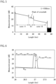
- FIG. 5 is a diagram illustrating a measurement result of emitted light received by the OTDR 20.
- the horizontal axis represents the propagation distance of the incident light L
- the vertical axis represents the power of the emitted light received by the OTDR 20.
- the vertical axis in FIG. 5 represents the ratio of the power of the emitted light to a predetermined power defined in the OTDR 20 in decibels. For example, when the predetermined power is 1 mW, the unit of the vertical axis may be indicated by dBm. As illustrated in FIG.
- backscattered light is measured as emitted light.
- the inclination of the line indicating the emitted light in these sections indicates a loss of the incident light L per unit length due to backscattering.
- pulsed light is measured at the boundary between the section of the core 11 and a section of the first optical fiber 51 and the boundary between the section of the first optical fiber 51 and the section of the core 12, and this light indicates reflection in the fan-in-fan-out device 40 or the like.
- Pulsed light is measured at substantially the midpoint of the section indicating the first optical fiber 51. As described above, since the incident light L and the crosstalk light CL1 pass each other at substantially the midpoint of the first optical fiber 51, this pulsed light indicates the crosstalk light CL1. In addition, also in the section where the incident light L propagates through the first optical fiber 51, the backscattered light is measured as the emitted light. Therefore, the power of the emitted light measured at substantially the midpoint of the first optical fiber 51 includes the power of the crosstalk light CL1 and the power of the backscattered light.
- a pulse indicating the power of the crosstalk light CL1 is illustrated at substantially the midpoint of the section indicating the first optical fiber 51.
- the pulse width of the incident light L and the pulse width of the crosstalk light CL1 are substantially the same. Therefore, in order to prevent the pulse indicating the crosstalk light CL1 from being applied to an end of the first optical fiber 51, the length of the core of the first optical fiber 51 as the first connection optical waveguide is preferably longer than the half width of the incident light L.
- the length of the first optical fiber 51 is L SCF
- the half-value time width of the incident light L is ⁇ T pulse
- the refractive index of the core of the first optical fiber 51 is n
- the high speed is c
- the OTDR 20 outputs data related to the measured power of the emitted light to the processing unit 25.
- the processing unit 25 obtains the power P BS of the backscattered light by, for example, linearly approximating the power of the emitted light in the region other than the region where the pulsed light is indicated.
- the processing unit 25 obtains a difference between power P OUT of the emitted light in the region where the pulsed light is indicated and the obtained power P BS of the backscattered light. This difference is the power of the pulsed light.
- the power of the pulsed light includes power P XT_MCF of the crosstalk light CL1 and power P XT_FIFO of crosstalk in the fan-in-fan-out devices 30 and 40.
- the processing unit 25 converts the obtained power P XT_MCF of the crosstalk light CL1 into the magnitude of the crosstalk and outputs the magnitude of the crosstalk.
- the processing unit 25 may convert the magnitude of the crosstalk into decibels indicating the ratio of the power of the incident light L emitted from the one end 17 of the core 12 and output the decibels.
- the processing unit 25 may perform decibel conversion indicating a ratio with respect to the predetermined power defined in the OTDR 20 illustrated in FIGS. 5 and 6 and output the result. In this way, the magnitude of crosstalk is obtained.
- FIG. 7 is a diagram illustrating the power of pulsed light including the crosstalk light CL1 in the multicore fiber 10 and the crosstalk light in the fan-in-fan-out devices 30 and 40 measured by the OTDR 20 as in the above embodiment, and the power of backscattered light is excluded from the power of light incident on the OTDR 20.
- the lengths of the multicore fiber 10 are set to 0 km, 21 km, 42 km, and 84 km.
- FIFO indicated by a dotted line in FIG. 7 indicates that the fan-in-fan-out device 30 and the fan-in-fan-out device 40 are directly connected and the length of the multicore fiber 10 is 0 km, and corresponds to the power P XT_FIFO described above.
- FIG. 7 it can be seen that the longer the multicore fiber 10, the larger the power of light generated by crosstalk.
- the fan-in-fan-out devices 30 and 40 were connected to the multicore fibers 10 used for the measurement of FIG. 7 , and the magnitude of crosstalk was measured by the PM method. Specifically, light is incident from the core of the optical fiber 31 of the fan-in-fan-out device 30 optically connected to the core 11 of the multicore fiber 10, and light emitted from the cores of the optical fibers 41 and 42 of the fan-in-fan-out device 40 optically connected to the core 12 of the multicore fiber 10 is measured to measure the magnitude of crosstalk between the core 11 and the core 12. Therefore, the magnitude of the crosstalk is the ratio of the power of the crosstalk light to the power of the incident light L emitted from the one end 17 of the core 12. The above results are indicated in Table 1 below.
- Table 1 peak size and crosstalk value at each fiber lengths Fiber Length (km) Peak size (dB) Crosstalk (dB) 0 (Only FIFO) 1.0 -57.1 21 3.7 -48.3 42 5.9 -42.7 84 8.8 -37.0
- Peak Size in Table 1 is the power of the pulsed light illustrated in FIG. 7
- Crosstalk is the magnitude of crosstalk measured by the PM method.
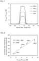
- FIG. 8 is a diagram illustrating a relationship between the power of the crosstalk light measured in the present embodiment and the power of the crosstalk light measured by the PM method illustrated in Table 1. As illustrated in FIG. 8 , these relationships are linear. Therefore, it is illustrated that the power of the crosstalk light measured by the crosstalk measuring method of the present embodiment is substantially correlated with the magnitude of the crosstalk measured by the PM method.
- the straight line is expressed by the following expression.
- XT 2.57 ⁇ ⁇ 58.9
- R 2 0.986
- XT represents the magnitude of crosstalk
- x represents the power of the crosstalk light
- R 2 is a determination coefficient. In this way, it is illustrated that the coefficient of determination is considerably close to 1 and the correlation is high.
- XT calculation is the magnitude of crosstalk obtained using the above-described linear approximation expression
- XT measurement is the magnitude of crosstalk measured by the PM method.
- the result of the measurement of the crosstalk according to the present embodiment and the result of the measurement of the crosstalk according to the PM method substantially matched each other. Therefore, in the processing step S3, in a case where the processing unit 25 converts the magnitude of the crosstalk into a decibel indicating the ratio of the power of the incident light L output from the one end 17 of the core 12, the magnitude XT of the crosstalk may be obtained from the expression of linear approximation with the power of the pulsed crosstalk light as x.
- the length of the multicore fiber 10 is defined as L MCF
- the length of the first optical fiber 51 is defined as L SCF .
- power when the incident light L enters the core 11 of the multicore fiber 10 from the one end 17 is defined as P 0
- power when the incident light L is emitted from the other end 18 is defined as P' 0
- power when the incident light L enters the core 12 from the other end 18 and is emitted from the one end 17 of the core 12 is defined as P" 0 .
- power of crosstalk light emitted from the core 12 after crosstalk from the core 11 to the core 12 while the incident light L propagates through the core 11 is defined as P XT (L MCF )
- power of crosstalk light emitted from the core 11 after crosstalk between the core 11 and the core 12 while the incident light L propagates through the core 11 and the core 12, that is, while the incident light L reciprocates through the multicore fiber 10 is defined as P XT (2L MCF ).
- the multicore fiber 10 will be described as a two-core fiber including the cores 11 and 12 but not including the cores 13 and 14.
- transmission losses of the multicore fiber 10 and the first optical fiber 51 are ignored, and losses and crosstalk in the fan-in-fan-out devices 30 and 40 are also ignored.
- P' 0 , P" 0 , P XT (L MCF ), and P XT (2L MCF ) are expressed by the following Expressions (1) to (4).
- h is a power coupling coefficient between the core 11 and the core 12 that cause crosstalk.
- the unit of the power of the light here is not expressed in decibels, but is expressed in watts, for example.
- magnitude indicating the magnitude of crosstalk from the core 11 to the core 12 while the incident light L propagates through the core 11 as a ratio to P' 0 in decibels is defined as XT(L MCF )
- magnitude indicating the magnitude of crosstalk between the core 11 and the core 12 while the incident light L propagates through the core 11 and the core 12, that is, while the incident light L reciprocates through the multicore fiber 10 as a ratio to P" 0 in decibels is defined as XT (2L MCF ).
- XT (L MCF ) and XT (2L MCF ) are expressed by the following Expressions (5) and (6).
- XT L MCF 10 ⁇ log 10 P XT L MCF / P ′ 0
- XT 2 L MCF 10 ⁇ log 10 P XT 2 L MCP / P " 0
- the OTDR 20 is optically connected to the core 11 at the one end 17 of the multicore fiber 10. Therefore, P" 0 cannot be measured in the OTDR. Therefore, to obtain the XT(2L MCF ) from the power of the light measured by the OTDR 20, Expression (6) only needs to be used as follows.
- the incident light L and the crosstalk light CL1 pass by each other at substantially the midpoint of the first optical fiber 51.
- the propagation distance of the incident light L is a half L SCF /2 of the length L MCF of the multicore fiber 10 and the length of the first optical fiber 51. Therefore, the distance from the midpoint of the first optical fiber 51 to the one end 17 of the multicore fiber 10 is L MCF + L SCF /2.
- P BS (L MCF + L SCF /2) is expressed by Expression (7).
- P BS L MCF + L SCF / 2 P 0 ⁇ ⁇ S_SCF ⁇ B SCF ⁇ 1 + exp ⁇ 2 h ⁇ 2 L MCF / 2
- ⁇ S_SCF represents the probability that the incident light L is Rayleigh scattered by the first optical fiber 51 with the backscattering coefficient of the first optical fiber 51
- B SCF represents the probability that the light Rayleigh scattered at a capture rate of the first optical fiber 51 propagates through the core of the first optical fiber 51 toward the core 11 of the multicore fiber 10.
- Expression (8) is derived from Expressions (2) and (7).
- P BS L MCF + L SCF / 2 ⁇ S_SCF ⁇ B SCF ⁇ P " 0
- the P BS (L MCF + L SCF /2) can be obtained from the power of the emitted light in the region other than the region in which the pulsed crosstalk light is indicated on the basis of data input from the OTDR 20.
- the power P XT_MCF described in the processing step S3 is P XT (2L MCF ). Therefore, P XT (2L MCF )can be obtained as described in the processing step S3. Therefore, by separately calculating the first term of Expression (9), XT(2L MCF ) can be obtained from Expression (9).
- the first term of Expression (9) may be obtained from the relationship between the magnitude of the crosstalk obtained in advance by the PM method and P BS (L MCF + L SCF /2) and P XT (2L MCF ) measured by the OTDR 20, or the first term of Expression (9) may be obtained by measuring the first optical fiber 51 in advance.
- the crosstalk measuring method includes the connecting step S1 of optically connecting the other end 18 of the core 11 that is the first optical waveguide and the other end 18 of the core 12 that is the second optical waveguide via the core of the first optical fiber 51 that is the first connection optical waveguide; the first measuring step S2 of causing pulsed incident light L emitted from the OTDR 20 to enter from the one end 17 of the core 11, and measuring power of emitted light emitted from the one end 17 of the core 11 by the OTDR 20, the emitted light including pulsed crosstalk light CL1 in which light generated by crosstalk of the incident light L from the core 11 to the core 12 and light generated by crosstalk of the incident light L incident from the core 11 to the core 12 via the core of the first optical fiber 51, the crosstalk being from the core 12 to the core 11, are multiplexed, the processing step S3 of obtaining the magnitude of the crosstalk between the core 11 and the core 12 using the measured power of the emitted light.
- the crosstalk measuring device of the present embodiment includes the core of the first optical fiber 51 that optically connects the other end 18 of the core 11 and the other end 18 of the core 12, the OTDR 20 that causes the pulsed incident light L to enter from the one end 17 of the core 11, and measures power of emitted light emitted from the one end 17 of the core 11, the emitted light including pulsed crosstalk light CL1 in which light generated by crosstalk of the incident light L from the core 11 to the core 12 and light generated by crosstalk of the incident light L incident from the core 11 to the core 12 via the core of the first optical fiber 51, the crosstalk being from the core 12 to the core 11 are multiplexed, and the processing unit 25 that obtains the magnitude of the crosstalk between the core 11 and the core 12 by using the measured power of the emitted light.
- the crosstalk measuring method and the crosstalk measuring device of the present embodiment since light in which the light incident on the core 11 using the OTDR 20 causes crosstalk to the core 12 is used, the power of the crosstalk light is large as compared with the case of detecting the backscattered light of the crosstalk light as in Patent Literatures 2 and 3. Furthermore, in the crosstalk measuring method and the crosstalk measuring device of the present embodiment, since light that causes crosstalk when the incident light L propagates from the one end 17 to the other end 18 of the core 11 and light that causes crosstalk when the incident light L propagates from the other end 18 to the one end 17 of the core 12 are multiplexed, the power of the pulsed crosstalk light CL1 generated by the crosstalk tends to be large. Therefore, by the crosstalk measuring method and the crosstalk measuring device of the present aspect, the crosstalk can be easily measured.
- FIG. 9 is a flowchart illustrating a procedure of a crosstalk measuring method in the present embodiment.
- the method for measuring crosstalk according to the present embodiment is different from the method for measuring crosstalk according to the first embodiment in that a second measuring step S22 is included.
- the connecting step S1 and the first measuring step S2 are performed similarly to those in the crosstalk measuring method of the first embodiment.
- FIG. 10 is a diagram illustrating a state of the crosstalk measuring device in this step.
- the core of the optical fiber 32 of the fan-in-fan-out device 30 is connected to the OTDR 20.
- the optical waveguide connected to the core of the optical fiber 32 is connected to the core 12 of the multicore fiber 10. Therefore, the optical fiber 32 and the core 12 are optically connected, and the light emitted from the OTDR 20 enters the core 12 from the one end 17.
- the power of light backscattered when propagating through the core 11 from the one end 17 to the other end 18 and the power of light backscattered when propagating through the core 11 from the other end 18 to the one end 17 are averaged, and an inclination of the distribution of the power of light in the range of the core 11 in FIG. 5 is substantially eliminated.
- an inclination of the distribution of the power of light indicating the range of the core 12 in FIG. 5 and an inclination of the distribution of the power of light in the range of the first optical fiber 51 are substantially eliminated.
- crosstalk light obtained by averaging the crosstalk light CL1 and the crosstalk light CL2 appears to be pulsed at substantially the midpoint of the first optical fiber 51.
- the power of the incident light L incident on the core 11 in the first measuring step S2 and the power of the incident light L incident on the core 12 in the second measuring step S22 are equal to each other, and in the processing step S3, the magnitude of the crosstalk between the core 11 and the core 12 is obtained using a result of averaging the power of the emitted light measured in the first measuring step S2 and the power of the emitted light measured in the second measuring step S22.
- the magnitude of crosstalk can be easily and accurately obtained.
- the power of the incident light L incident on the core 11 in the first measuring step S2 and the power of the incident light L incident on the core 12 in the second measuring step S22 may be different from each other.
- a procedure of the crosstalk measuring method of the present embodiment using such a crosstalk measuring device 1 is similar to the flowchart illustrated in FIG. 3 . However, the respective steps are different as follows. Differences will be mainly described below.
- the first optical fiber 51 and the second optical fiber 52 are connected to the optical fiber 41 via the coupler 55, and the end of the second optical fiber 52 on the side opposite to the coupler 55 is connected to the optical fiber 43. That is, in the present embodiment, in addition to the connecting step S1 in the first embodiment, the other end 18 of the core 11 and the other end 18 of the core 13 are optically connected via a core of a second optical fiber having a length different from that of the first optical fiber 51. In this way, the core 11 and the core 12 are optically connected, and the core 11 and the core 13 are optically connected.
- the incident light L is caused to enter the core 11 from the OTDR 20 as in the first embodiment.
- crosstalk occurs as follows in addition to the crosstalk between the core 11 and the core 12 described in the first embodiment, and the crosstalk is measured. This will be described below.
- the incident light L incident on the core 11 from the OTDR 20 propagates through the core 11 from the one end 17 to the other end 18, and propagates while causing crosstalk from the core 11 to the core 12, and causing crosstalk from the core 11 to the core 13.
- the light causing crosstalk from the core 11 to the core 13 is also pulsed, and propagates from the one end 17 side to the other end 18 of the core 13 while traveling substantially in parallel with the incident light L.
- the power of the crosstalk light CL2 increases according to the distance propagated through the core 13.
- the crosstalk light CL2 enters the second optical fiber 52 from the optical fiber 43 at substantially the same timing as when the incident light L enters the second optical fiber 52 from the coupler 55.
- the incident light L and the crosstalk light CL2 pass by each other at substantially a midpoint of the second optical fiber 52. Then, the incident light L enters the core 13 at the other end 18 of the multicore fiber 10 via the fan-in-fan-out device 40, and the crosstalk light CL2 enters the core 11 at substantially the same timing as the timing at which the incident light L enters the core 13.
- the incident light L incident on the core 13 and the crosstalk light CL2 incident on the core 11 propagate through the respective cores 13 and 11 toward the one end 17 while traveling substantially in parallel. During this time, the incident light L propagating through the core 13 propagates to the core 11 while causing crosstalk.
- FIG. 12 is a diagram illustrating a measurement result in the OTDR according to the present embodiment. Since the length of the first optical fiber 51 and the length of the second optical fiber 52 are different from each other, as illustrated in FIG. 12 , the emitted light including the crosstalk light CL1 and the emitted light including the crosstalk light CL2 are incident on the OTDR 20 at different timings. In the present embodiment, since the second optical fiber 52 is longer than the first optical fiber 51, the emitted light including the crosstalk light CL2 enters the OTDR at a timing later than that of the emitted light including the crosstalk light CL1. Therefore, the OTDR 20 can measure the emitted light of each of them. Thus, the OTDR 20 measures the power of the emitted light including the pulsed light twice.
- the difference between the length of the first optical fiber 51 and the length of the second optical fiber 52 is preferably larger than the half width of the incident light. In this case, the interference between the pulsed light due to the crosstalk between the core 11 and the core 12 and the pulsed light due to the crosstalk between the core 11 and the core 13 can be suppressed, and the magnitude of the crosstalk can be more accurately measured.
- the processing unit 25 obtains the magnitude of the crosstalk between the core 11 and the core 12 as in the first embodiment using the measured power of the emitted light. Further, in this step of the present embodiment, the processing unit 25 obtains the magnitude of the crosstalk between the core 11 and the core 13. Since the backscattered light is also generated in the first optical fiber 51 and the second optical fiber 52, the power of the backscattered light is measured in a region other than the region where the pulsed light including the crosstalk light CL2 is indicated.
- the processing unit 25 obtains the power of the backscattered light in the region where the pulsed light including the crosstalk light CL2 is indicated from the power of the emitted light in the region other than the region where the pulsed light including the crosstalk light CL2 is indicated. Specifically, the processing unit 25 obtains the power of the backscattered light in the emitted light including the crosstalk light CL2 in a manner similar to when obtaining the power P BS of the backscattered light in the first embodiment. Next, the processing unit 25 obtains a difference between the power of the emitted light in the region where the pulsed light including the crosstalk light CL2 is indicated and the obtained power of the backscattered light.
- This difference is the power of the crosstalk light CL2.
- the power P XT_FIFO of the crosstalk in the fan-in-fan-out devices 30 and 40 is negligibly small, the power may be ignored.
- the processing unit 25 converts the power of the crosstalk light CL1 obtained as in the first embodiment into the magnitude of the crosstalk and outputs the magnitude of the crosstalk, and converts the power of the obtained crosstalk light CL2 into the magnitude of the crosstalk and outputs the magnitude of the crosstalk.
- the processing unit 25 may convert the magnitude of the crosstalk light CL2 into decibels indicating the ratio of the power of the incident light L emitted from the one end 17 of the core 13 and output the decibels.
- the processing unit 25 may convert the power into decibels indicating the ratio with respect to the predetermined power defined in the OTDR 20 and output the decibels. In this way, the magnitude of the crosstalk between the core 11 and the core 12 as well as the magnitude of the crosstalk between the core 11 and the core 13 are obtained.
- the other end 18 of the core 11 and the other end 18 of the core 13 are further optically connected via the core of the second optical fiber 52 having a length different from that of the core of the first optical fiber 51, and in the first measuring step S2, power of emitted light emitted from the one end 17 of the core 11 is further measured by the OTDR 20, the emitted light including pulsed light in which light generated by crosstalk of the incident light L from the core 11 to the core 13 and light generated by crosstalk of the incident light L incident on the core 13 from the core 11 via the core of the second optical fiber 52, the crosstalk being from the core 13 to the core 11, are multiplexed, and in the processing step S3, the magnitude of the crosstalk between the core 11 and the core 13 is further obtained by using the power of the emitted light including the pulsed crosstalk light CL2 generated by the crosstalk between the core 11 and the core 13.
- the crosstalk measuring device 1 of the present embodiment further includes the core of the second optical fiber 52 having a length different from that of the core of the first optical fiber 51 that optically connects the other end 18 of the core 11 and the other end 18 of the core 13, the OTDR 20 further measures power of emitted light emitted from the one end 17 of the core 11, the emitted light including pulsed light in which light generated by crosstalk of the incident light L from the core 11 to the core 13 and light generated by crosstalk of the incident light L incident on the core 13 from the core 11 via the core of the second optical fiber 52, the crosstalk being from the core 13 to the core 11, are multiplexed, and the processing unit 25 further obtains the magnitude of the crosstalk between the core 11 and the core 13 by using the power of the emitted light including the pulsed crosstalk light CL2 generated by the crosstalk between the core 11 and the core 13.
- the emitted light including the crosstalk light between the core 11 and the core 12 and the emitted light including the crosstalk light between the core 11 and the core 13 can each be received by the OTDR 20, the power of each emitted light can be measured, and the magnitude of each crosstalk can be obtained.
- the magnitude of the crosstalk between the core 11 and the core 12 and the magnitude of the crosstalk between the core 11 and the core 13 can be easily measured as compared with a case where the magnitude of the crosstalk between the core 11 and the core 12 is measured as in the first embodiment, the core 11 and the core 13 are further optically connected thereafter by the connection optical waveguide, the incident light is incident again from the one end 17 of the core 11, and the magnitude of the crosstalk between the core 11 and the core 13 is measured.
- the second optical fiber 52 is longer than the first optical fiber 51, but the length of the first optical fiber 51 and the length of the second optical fiber 52 only needs to be different, and the first optical fiber 51 may be longer than the second optical fiber 52.
- FIG. 13 is a diagram illustrating a state of the crosstalk measuring device according to the present embodiment in a manner similar to FIG. 4 .
- a crosstalk measuring device 1 of the present embodiment is different from the crosstalk measuring device 1 of the first embodiment in that the crosstalk measuring device 1 includes a second optical fiber 52, and one end 17 of a core 12 that is a second optical waveguide and one end of a core 13 that is a third optical waveguide are optically connected via a core of the second optical fiber 52 that is a second connection optical waveguide.
- the length of the first optical fiber 51 and the length of the second optical fiber 52 may be different from each other or may be the same.
- a procedure of the crosstalk measuring method of the present embodiment using such a crosstalk measuring device 1 is similar to the flowchart illustrated in FIG. 3 . However, the respective steps are different as follows. Differences will be mainly described below.
- the one end 17 of the core 12 and the one end 17 of the core 13 are optically connected via the core of the second optical fiber 52.
- one end of the second optical fiber 52 is connected to the optical fiber 32 of the fan-in-fan-out device 30, and the other end of the second optical fiber 52 is connected to the optical fiber 33 of the fan-in-fan-out device 30.
- the core 12 and the core 13 are optically connected.
- the incident light L is caused to enter the core 11 from the OTDR 20 as in the first embodiment.
- crosstalk occurs as follows in addition to the crosstalk between the core 11 and the core 12 described in the first embodiment, and the crosstalk is measured. This will be described below.
- the incident light L incident on the core 11 from the OTDR 20 propagates through the core 11 from one end 17 to the other end 18, and then enters the core 12 via the first optical fiber 51.
- the incident light L propagating through the core 12 from the other end 18 to the one end 17 causes crosstalk from the core 12 to the core 11 as described in the first embodiment, and causes crosstalk from the core 12 to the core 13.
- the light causing crosstalk from the core 12 to the core 13 is also pulsed, and propagates from the other end 18 side of the core 13 to the one end 17 while traveling substantially in parallel with the incident light L.
- the power of the crosstalk light CL2 increases according to the distance propagated through the core 13.
- the incident light L enters the core 13 from the core 12 via the second optical fiber 52, and the crosstalk light CL2 enters the core 12 from the core 13 via the second optical fiber 52.
- the incident light L and the crosstalk light CL2 pass by each other at substantially a midpoint of the second optical fiber 52. Therefore, the timing at which the incident light L enters the core 13 is substantially the same as the timing at which the crosstalk light CL2 enters the core 12.
- the incident light L incident on the core 13 and the crosstalk light CL2 incident on the core 12 propagate through the respective cores 13 and 12 from one end 17 to the other end 18 while traveling substantially in parallel. During this time, the incident light L propagating through the core 13 propagates to the core 12 while causing crosstalk.
- the light crosstalk from the core 13 to the core 12 is multiplexed with the crosstalk light CL2 propagating through the core 12.
- the multiplexed light is pulsed and propagates while gradually increasing power.
- the light including the pulsed crosstalk light CL2 enters the core 11 from the core 12 via the first optical fiber 51, and emitted light in which light such as backscattered light is multiplexed with the crosstalk light CL2 is emitted from one end 17 of the core 11. Therefore, the emitted light includes the pulsed crosstalk light CL2.
- the emitted light emitted from the core 11 enters the OTDR 20 and received by the OTDR 20, and its power is measured by the OTDR 20.
- the timing at which the emitted light including the crosstalk light CL2 enters the OTDR 20 is delayed by the time during which the light propagates through the second optical fiber 52, the core 12, the first optical fiber 51, and the core 11 with respect to the timing at which the emitted light including the crosstalk light CL1 enters the OTDR 20. Therefore, the OTDR 20 can measure the emitted light of each of them. Therefore, the OTDR 20 measures the power of the pulsed light twice.
- the processing unit 25 obtains the magnitude of the crosstalk between the core 11 and the core 12 as in the first embodiment using the measured power of the emitted light. Furthermore, in this step of the present embodiment, the processing unit 25 obtains the magnitude of the crosstalk between the core 12 and the core 13.
- the method of obtaining the crosstalk between the core 12 and the core 13 is similar to the method of obtaining the crosstalk between the core 11 and the core 13 in the third embodiment.
- the processing unit 25 converts the power of the crosstalk light CL1 obtained as in the first embodiment into the magnitude of the crosstalk and outputs the magnitude of the crosstalk, and converts the power of the obtained crosstalk light CL2 into the magnitude of the crosstalk and outputs the magnitude of the crosstalk.
- the processing unit 25 may convert the magnitude of the crosstalk into decibels indicating the ratio of the power of the incident light L emitted from the other end 18 of the core 13 and output the decibels.
- the processing unit 25 may convert the power into decibels indicating the ratio with respect to the predetermined power defined in the OTDR 20 and output the decibels. In this way, the magnitude of the crosstalk between the core 11 and the core 12 as well as the magnitude of the crosstalk between the core 11 and the core 13 are obtained.
- the crosstalk measuring method of the present embodiment in addition to the crosstalk measuring method of the first embodiment, in the connecting step S1, one end 17 of the core 12 and one end 17 of the core 13 are further optically connected via the core of the second optical fiber 52, in the first measuring step S2, power of emitted light emitted from the one end 17 of the core 11 is further measured by the OTDR 20 via the first optical fiber 51 and the core 11, the emitted light including pulsed light in which light generated by crosstalk of the incident light L from the core 12 to the core 13 and light generated by crosstalk of the incident light L incident from the core 12 to the core 13 via the core of the second optical fiber 52, the crosstalk being from the core 13 to the core 12, are multiplexed, and in the processing step S3, the magnitude of the crosstalk between the core 12 and the core 13 is further obtained using the power of the emitted light including the pulsed crosstalk light CL2 generated by the crosstalk between the core 12 and the core 13.
- the crosstalk measuring device 1 of the present embodiment further includes the core of the second optical fiber 52 that optically connects the one end 17 of the core 12 and the one end 17 of the core 13, the OTDR 20 further measures power of emitted light emitted from the one end 17 of the core 11 via the first optical fiber 51 and the core 11, the emitted light including pulsed light in which light generated by crosstalk of the incident light L from the core 12 to the core 13 and light generated by crosstalk of the incident light L incident on the core 13 from the core 12 via the core of the second optical fiber 52, the crosstalk being from the core 13 to the core 12, are multiplexed, and the processing unit 25 further obtains the magnitude of the crosstalk between the core 12 and the core 13 by using the power of the emitted light including the pulsed crosstalk light CL2 generated by the crosstalk between the core 12 and the core 13.
- the emitted light including the crosstalk light between the core 11 and the core 12 and the emitted light including the crosstalk light between the core 12 and the core 13 can each be received by the OTDR 20, the power of each emitted light can be measured, and the magnitude of each crosstalk can be obtained.
- the magnitude of the crosstalk between the core 11 and the core 12 and the magnitude of the crosstalk between the core 12 and the core 13 can be easily measured as compared with a case where the magnitude of the crosstalk between the core 11 and the core 12 is measured as in the first embodiment, the core 12 and the core 13 are further optically connected thereafter by the connection optical waveguide, the incident light is incident again from the one end 17 of the core 11, and the magnitude of the crosstalk between the core 12 and the core 13 is measured.
- a second measuring step S22 may be provided after the first measuring step S2.
- the pulsed incident light L emitted from the OTDR 20 is caused to enter from the other end 18 of the core 13.
- the OTDR 20 measures power of emitted light emitted from the other end 18 of the core 13, the emitted light including pulsed light in which light generated by crosstalk of the incident light L from the core 13 to the core 12 and light generated by crosstalk of the incident light L incident from the core 13 to the core 12 via the second optical fiber 52, the crosstalk being from the core 12 to the core 13, are multiplexed.
- the OTDR 20 measures power of emitted light emitted from the other end 18 of the core 13 via the second optical fiber 52 and the core 13 from the one end 17 of the core 12, the emitted light including pulsed light in which light generated by crosstalk from the core 12 to the core 11 while the incident light L propagates through the core 12 from the one end 17 to the other end 18 and light generated by crosstalk of the incident light L incident on the core 11 via the first optical fiber 51, the crosstalk being from the core 11 to the core 12, are multiplexed.
- the magnitude of the crosstalk between the core 12 and the core 13 is obtained using the power of the emitted light measured in the first measuring step S2 and the power of the emitted light measured in the second measuring step S22.
- FIG. 14 is a diagram illustrating a state of the crosstalk measuring device according to the present embodiment in a manner similar to FIG. 4 .
- a crosstalk measuring device 1 of the present embodiment is different from the crosstalk measuring device 1 of the first embodiment in that it includes a second optical fiber 52 as a second connection waveguide, and one end 17 of a core 12 as a second optical waveguide and the other end of the core 13 as a third optical waveguide are optically connected via the second optical fiber 52.
- the length of the first optical fiber 51 and the length of the second optical fiber 52 may be different from each other or may be the same.
- a procedure of the crosstalk measuring method of the present embodiment using such a crosstalk measuring device 1 is similar to the flowchart illustrated in FIG. 3 . However, the respective steps are different as follows. Differences will be mainly described below.
- the one end 17 of the core 12 and the other end 18 of the core 13 are optically connected via the core of the second optical fiber 52.
- one end of the second optical fiber 52 is connected to the optical fiber 32 of the fan-in-fan-out device 30, and the other end of the second optical fiber 52 is connected to the optical fiber 43 of the fan-in-fan-out device 40.
- the core 12 and the core 13 are optically connected.
- the incident light L is caused to enter the core 11 from the OTDR 20 as in the first embodiment.
- crosstalk occurs as follows in addition to the crosstalk between the core 11 and the core 12 described in the first embodiment, and the crosstalk is measured. This will be described below.
- the incident light L incident on the core 11 from the OTDR 20 propagates through the core 11 from the one end 17 to the other end 18, and propagates while causing crosstalk from the core 11 to the core 12, and causing crosstalk from the core 11 to the core 13.
- the light causing crosstalk from the core 11 to the core 13 is also pulsed, and propagates from the one end 17 side to the other end 18 of the core 13 while traveling substantially in parallel with the incident light L.
- the power of the crosstalk light CL2 increases according to the distance propagated through the core 13.
- the incident light L and the crosstalk light CL2 reach the other end 18 at substantially the same timing.
- the incident light L enters the core 13 from the other end 18 of the core 13 via the first optical fiber 51, the core 12, and the second optical fiber 52 from the other end 18 of the core 11.
- the crosstalk light CL2 enters the core 11 from the other end 18 of the core 11 via the second optical fiber 52, the core 12, and the first optical fiber 51 from the other end 18 of the core 13.
- the incident light L and the crosstalk light CL2 pass by each other at substantially a midpoint of a waveguide in which the core of the first optical fiber 51, the core 12, and the core of the second optical fiber 52 are multiplexed. Therefore, the timing at which the incident light L enters the core 13 is substantially the same as the timing at which the crosstalk light CL2 enters the core 11.
- the incident light L incident on the core 13 and the crosstalk light CL2 incident on the core 11 propagate through the cores 13 and 11 from the other end 18 toward the one end 17 while traveling substantially in parallel. During this time, the incident light L propagating through the core 13 propagates to the core 11 while causing crosstalk. Therefore, the light causing crosstalk from the core 13 to the core 11 is multiplexed with the crosstalk light CL2 propagating through the core 11.
- the multiplexed light is pulsed and propagates while gradually increasing power. From the one end 17 of the core 11, emitted light in which light such as backscattered light is multiplexed with the pulsed crosstalk light CL2 is emitted. Therefore, the emitted light includes the pulsed crosstalk light CL2.
- the emitted light emitted from the core 11 enters the OTDR 20 and received by the OTDR 20, and its power is measured by the OTDR 20.
- the timing at which the emitted light including the crosstalk light CL2 enters the OTDR 20 is delayed by the time during which the light propagates through the second optical fiber 52 and the core 13 with respect to the timing at which the emitted light including the crosstalk light CL1 enters the OTDR 20. Therefore, the OTDR 20 can measure the emitted light of each of them. Therefore, the OTDR 20 measures the power of the pulsed light twice.
- the processing unit 25 obtains the magnitude of the crosstalk between the core 11 and the core 12 as in the first embodiment using the measured power of the emitted light. Further, in this step of the present embodiment, the processing unit 25 obtains the magnitude of the crosstalk between the core 11 and the core 13.
- the method of obtaining the crosstalk between the core 11 and the core 13 is similar to the method of obtaining the crosstalk between the core 11 and the core 13 in the third embodiment.
- the processing unit 25 converts the power of the crosstalk light CL1 obtained as in the first embodiment into the magnitude of the crosstalk and outputs the magnitude of the crosstalk, and converts the power of the obtained crosstalk light CL2 into the magnitude of the crosstalk and outputs the magnitude of the crosstalk.
- the processing unit 25 may convert the magnitude of the crosstalk into decibels indicating the ratio of the power of the incident light L emitted from the one end 17 of the core 13 and output the decibels.
- the processing unit 25 may convert the power into decibels indicating the ratio with respect to the predetermined power defined in the OTDR 20 and output the decibels. In this way, the magnitude of the crosstalk between the core 11 and the core 12 as well as the magnitude of the crosstalk between the core 11 and the core 13 are obtained.
- the crosstalk measuring method of the present embodiment in addition to the crosstalk measuring method of the first embodiment, in the connecting step S1, one end 17 of the core 12 and the other end 18 of the core 13 are further optically connected via the core of the second optical fiber 52, in the first measuring step S2, power of emitted light emitted from the one end 17 of the core 11 is further measured by the OTDR 20, the emitted light including pulsed light in which light generated by crosstalk of the incident light L from the core 11 to the core 13 and light generated by crosstalk of the incident light L incident on the core 13 from the core 11 via the core 12 and the core of the second optical fiber 52, the crosstalk being from the core 13 to the core 11, are multiplexed, and in the processing step S3, the magnitude of the crosstalk between the core 11 and the core 13 is further obtained using the power of the emitted light including the pulsed crosstalk light CL2 generated by the crosstalk between the core 11 and the core 13.
- the crosstalk measuring device 1 of the present embodiment further includes the core of the second optical fiber 52 that optically connects the one end 17 of the core 12 and the other end 18 of the core 13, the OTDR 20 further measures power of emitted light emitted from the one end 17 of the core 11, the emitted light including pulsed light in which light generated by crosstalk of the incident light L from the core 11 to the core 13 and light generated by crosstalk of the incident light L incident on the core 13 from the core 11 via the core 12 and the core of the second optical fiber 52, the crosstalk being from the core 13 to the core 11, are multiplexed, and the processing unit 25 further obtains the magnitude of the crosstalk between the core 11 and the core 13 by using the power of the emitted light including the pulsed crosstalk light CL2 generated by the crosstalk between the core 11 and the core 13.
- the emitted light including the crosstalk light between the core 11 and the core 12 and the emitted light including the crosstalk light between the core 11 and the core 13 can each be received by the OTDR 20, the power of each emitted light can be measured, and the magnitude of each crosstalk can be obtained.
- the magnitude of the crosstalk between the core 11 and the core 12 and the magnitude of the crosstalk between the core 11 and the core 13 can be easily measured as compared with a case where the magnitude of the crosstalk between the core 11 and the core 12 is measured as in the first embodiment, the core 11 and the core 13 are further optically connected thereafter by the connection optical waveguide, the incident light is incident again from the one end 17 of the core 11, and the magnitude of the crosstalk between the core 11 and the core 13 is measured.
- a second measuring step S22 may be provided after the first measuring step S2.
- the pulsed incident light L emitted from the OTDR 20 is caused to enter from the one end 17 of the core 13.
- the OTDR 20 measures power of emitted light emitted from the one end 17 of the core 13, the emitted light including pulsed light in which light generated by crosstalk of the incident light L from the core 13 to the core 11 and light generated by crosstalk of the incident light L incident from the core 13 to the core 11 via the second optical fiber 52, the core 12, and the first optical fiber 51, the crosstalk being from the core 11 to the core 13, are multiplexed.
- the OTDR 20 measures power of emitted light emitted from the one end 17 of the core 13 via the second optical fiber 52 and the core 13 from the one end 17 of the core 12, the emitted light including pulsed light in which light generated by crosstalk from the core 12 to the core 11 while the incident light L propagates through the core 12 from the one end 17 to the other end 18 and light generated by crosstalk of the incident light L incident on the core 11 via the first optical fiber 51, the crosstalk being from the core 11 to the core 12, are multiplexed.
- the magnitude of the crosstalk between the core 11 and the core 13 is obtained using the power of the emitted light measured in the first measuring step S2 and the power of the emitted light measured in the second measuring step S22.
- the arrangement and number of cores of the multicore fiber 10 may be different from those in the above embodiment.
- the multicore fiber has been described as an example of the optical device in which the waveguides are arranged in parallel, but the optical device of the present invention is not limited to the multi-core fiber.
- the optical device of the present invention is not limited to the multi-core fiber.
- it is applicable to an optical fiber cable in which a plurality of optical fibers is arranged, an optical fiber tape in which a plurality of optical fibers is arranged in a planar manner, a multi-element fiber in which a plurality of optical fiber bare wires is arranged in one coating layer, and crosstalk measurement of the entire transmission system.
- At least one of a loss of light, a reflection intensity, a bending loss, or a disconnection in an optical device such as the multicore fiber 10 may be further measured by the OTDR 20.
- the forms of the fan-in-fan-out devices 30 and 40 are not particularly limited. Further, the crosstalk measuring device 1 need not include at least one of the fan-in-fan-out devices 30 and 40.
- the core of the multicore fiber 10 is directly connected to the core of the first optical fiber 51 or the core of the second optical fiber 52.
- at least one of the first optical fiber 51 and the second optical fiber 52 may include a connecting body of a plurality of optical fibers.
- the inclination of the power of the backscattered light measured by the OTDR 20 is substantially the same in the sections of the core 11, the core 12, the first optical fiber 51, and the like. This indicates that the loss of the incident light L per unit length due to backscattering is substantially the same in the sections of the core 11, the core 12, the first optical fiber 51, and the like. Therefore, in the above embodiment, when light of the same power is propagated to the core 11, the core 12, the first optical fiber 51, and the like, the power of the backscattered light per unit length generated in each section is substantially the same.
- the power of the backscattered light per unit length generated in the first optical fiber 51 is preferably smaller than the power of the backscattered light per unit length generated in each of the core 11 and the core 12.
- a first optical fiber 51 for example, a hollow core optical fiber having a hollow core can be exemplified.
- such a first optical fiber 51 may be an optical fiber in which the relative refractive index difference of the core of the first optical fiber 51 is smaller than that of light propagated through the core of the multicore fiber 10 and the effective cross-sectional area of the propagated light is larger.
- FIG. 15 is a schematic diagram illustrating a measurement result in the OTDR 20 in a case where a hollow core optical fiber is used as the first optical fiber 51 in FIG. 4 .
- FIG. 15 is a schematic diagram of a measurement result in the case of using a multicore fiber having two cores.
- the power of the backscattered light per unit length generated in the second optical fiber 52 of the third to fifth embodiments is preferably smaller than the power of the backscattered light per unit length generated in each of the cores 11 to 13.
- FIG. 16 is a diagram illustrating a modification of the crosstalk measuring device of the first embodiment.
- the present modification is different from the first embodiment in that the optical fibers 43 and 44 of the fan-in-fan-out device 40 are connected to the second optical fiber 52, and the other end 18 of the core 13 and the other end 18 of the core 14 are optically connected via the core of the second optical fiber 52.
- the length of the second optical fiber 52 is the same as the length of the first optical fiber 51.
- the distance in which light propagates from the other end 18 of the core 13 to the other end 18 of the core 14 is the same as the distance in which light propagates from the other end 18 of the core 11 to the other end 18 of the core 12.
- the pulsed light in which the crosstalk light CL1 in which the incident light causes crosstalk from the core 11 to the core 12 and the crosstalk light CL1 in which the incident light causes crosstalk from the core 12 to the core 11 are multiplexed is measured.
- the crosstalk light CL1 causing crosstalk from the core 11 to the core 12 also includes light in which light causing crosstalk from the core 11 to the cores 13 and 14 further causes crosstalk to the core 12.
- the light causing crosstalk from the core 12 to the core 11 also includes light in which light causing crosstalk from the core 12 to the cores 13 and 14 further causes crosstalk to the core 11.
- light that does not further cause crosstalk to the core 12 is emitted from the other end 18.
- the timing at which the crosstalk light CL1 emitted from the other end of the core 12 enters the other end of the core 11 is substantially the same as the timing at which light that does not further cause crosstalk to the core 12 out of light that has caused crosstalk from the core 11 to the cores 13 and 14 enters the cores 14 and 13 via the second optical fiber 52.
- the magnitude of crosstalk can be more accurately measured as compared with the first embodiment.
- a crosstalk measuring method and a crosstalk measuring device capable of easily measuring crosstalk using an OTDR method are provided, and are expected to be used in the field of optical fiber communication and the like.
Landscapes
- Physics & Mathematics (AREA)
- Optics & Photonics (AREA)
- Chemical & Material Sciences (AREA)
- Analytical Chemistry (AREA)
- General Physics & Mathematics (AREA)
- Engineering & Computer Science (AREA)
- Microelectronics & Electronic Packaging (AREA)
- Testing Of Optical Devices Or Fibers (AREA)
Abstract
Description
- The present invention relates to a crosstalk measuring method and a crosstalk measuring device.
- In response to an increase in the amount of information communication in recent years, an increase in transmission capacity of an optical fiber is demanded. A multicore fiber is attracting attention because it can increase space utilization efficiency and can transmit a large amount of information in a limited space. However, a plurality of cores is arranged in one optical fiber, and thus it is difficult to evaluate characteristics as compared with a single-core fiber. Therefore, a technique for efficiently evaluating a multicore fiber is demanded. In particular, measurement of crosstalk is an important measurement item in a multicore fiber and is not included in a measurement item of a single-core fiber, and thus it is necessary to newly prepare a measurement device or the like.
- As a crosstalk measuring method, a method described in the following Non Patent Literature is known.
Non Patent Literature 1 below discloses a Power Meter (PM) method. The PM method is a method in which light is caused to enter a predetermined core of a multicore fiber from one end of the core, and power of light emitted from the other end of the core in which crosstalk with the core occurs is measured.Non Patent Literatures -
- [Non Patent Literature 1]
K. Takenaga, Y. Arakawa, S. Tanigawa, N. Guan, S. Matsuo, K. Saitoh and M. Koshiba, "An Investigation on Crosstalk in Multi-Core Fibers by Introducing Random Fluctuation along Longitudinal Direction", IEICE TRAN. COMMUN., Vol.E94-B, No.2, 2011. - [Non Patent Literature 2]
M. Ohashi, K. Kawazu, A. Nakamura, and Y. Miyoshi, "Simple backscattered power technique for measuring crosstalk of multi-core fibers", OptoElectronics and Communications Conference, Busan, South Korea, P1-25, 2012, DOI: https://doi.org/10.1109/OECC.2012.6276724 - [Non Patent Literature 3]
M. Nakazawa, M. Yoshida, and T. Hirooka, "Nondestructive measurement of mode couplings along a multi-core fiber using a synchronous multi-channel OTDR", Optics Express, vol. 20, - In the PM method, it is necessary to cause light to enter from one end of a multicore fiber and receive light emitted from the other end. On the other hand, in the OTDR method, light is caused to enter from one end of a multicore fiber, and light emitted from the one end is received. Therefore, there is a need to measure the crosstalk using the OTDR method. However, in the crosstalk measuring methods described in
Non Patent Literatures - Therefore, an object of the present invention is to provide a crosstalk measuring method and a crosstalk measuring device capable of easily measuring crosstalk using an OTDR method.
- In order to solve the above problem, a first aspect of the present invention is a crosstalk measuring method for an optical device including a first optical waveguide and a second optical waveguide that include one end and another end and are parallel to each other, the crosstalk measuring method including a connecting step of optically connecting the another end of the first optical waveguide and the another end of the second optical waveguide via a first connection optical waveguide, a first measuring step of causing pulsed incident light emitted from an optical time domain reflectometer (OTDR) to enter from the one end of the first optical waveguide, and measuring power of emitted light emitted from the one end of the first optical waveguide by the OTDR, the emitted light including pulsed light in which light generated by crosstalk of the incident light from the first optical waveguide to the second optical waveguide and light generated by crosstalk of the incident light incident from the first optical waveguide to the second optical waveguide via the first connection optical waveguide, the crosstalk being from the second optical waveguide to the first optical waveguide, are multiplexed, and a processing step of obtaining magnitude of crosstalk between the first optical waveguide and the second optical waveguide by using the measured power of the emitted light.
- Pulsed incident light propagating from one end to the another end of the first optical waveguide propagates from the first optical waveguide to the second optical waveguide while causing crosstalk. Therefore, crosstalk light causing crosstalk from the first optical waveguide to the second optical waveguide is also pulsed, and propagates from one end side to the another end of the second optical waveguide while traveling substantially in parallel with the incident light. The incident light reaching the another end of the first optical waveguide enters the first connection optical waveguide. Further, the pulsed crosstalk light propagating from one end side of the second optical waveguide and reaching the another end of the second optical waveguide enters the first connection optical waveguide from an opposite side of the incident light. Since the speed of light in an optical device is constant, a propagation speed of incident light and a propagation speed of crosstalk light are equal to each other. Therefore, the incident light and the crosstalk light reach the another ends of the first optical waveguide and the second optical waveguide substantially simultaneously, and the incident light and the crosstalk light pass by each other at substantially a middle point of the first connection optical waveguide. Then, the incident light enters the second optical waveguide from the another end of the second optical waveguide, and the crosstalk light enters the first optical waveguide from the another end of the first optical waveguide. At this time, the timing at which the incident light enters the second optical waveguide and the timing at which the crosstalk light enters the first optical waveguide are substantially the same timing. Thus, the crosstalk light propagates through the first optical waveguide from the another end to the one end while traveling substantially in parallel with the incident light propagating through the second optical waveguide from the another end to the one end. During this time, the incident light propagating through the second optical waveguide propagates through the first optical waveguide while causing crosstalk. Therefore, the light causing crosstalk from the second optical waveguide to the first optical waveguide is multiplexed with the crosstalk light propagating through the first waveguide. The multiplexed light is pulsed light, and the emitted light emitted from the one end of the first optical waveguide includes pulse light generated by crosstalk. The light emitted from the first optical waveguide is received by the OTDR, and power of the emitted light is measured. The magnitude of the crosstalk between the first optical waveguide and the second optical waveguide is obtained using the measured power of the emitted light.
- As described above, according to the crosstalk measuring method of the present aspect, since light in which the light incident on the optical waveguide using the OTDR causes crosstalk to another optical waveguide is used, the power of crosstalk light is large as compared with the case of detecting backscattered light of the crosstalk light as in
Patent Literatures - A second aspect of the present invention is the crosstalk measuring method according to the first aspect, in which a length of the first connection optical waveguide is longer than a half width of the incident light.
- As described above, the incident light and the crosstalk light pass each other at substantially a midpoint of the first connection optical waveguide. Therefore, in the OTDR, it seems that the pulsed light generated by the crosstalk is generated at substantially the midpoint of the first connection optical waveguide. In addition, a pulse width of the incident light and a pulse width of the crosstalk light are substantially the same. Therefore, according to the crosstalk measuring method of the present aspect, noise such as reflection at an end of the first connection optical waveguide can be suppressed from affecting emitted light including pulsed crosstalk light, and the crosstalk can be measured more accurately.
- A third aspect of the present invention is the crosstalk measuring method according to the first or second aspect, further including a second measuring step of causing pulsed incident light emitted from the OTDR to enter from the one end of the second optical waveguide and measuring power of emitted light emitted from the one end of the second optical waveguide by the OTDR, the emitted light including pulsed light in which light generated by crosstalk of the incident light from the second optical waveguide to the first optical waveguide and light generated by crosstalk of the incident light incident from the second optical waveguide to the first optical waveguide via the first connection optical waveguide, the crosstalk being from the first optical waveguide to the second optical waveguide, are multiplexed, in which in the processing step, the magnitude of the crosstalk between the first optical waveguide and the second optical waveguide is obtained using the power of the emitted light measured in the first measuring step and the power of the emitted light measured in the second measuring step.
- In this case, the crosstalk light generated by propagating the incident light from the first optical waveguide to the second optical waveguide and the crosstalk light generated by propagating the incident light from the second optical waveguide to the first optical waveguide are used, so that errors can be suppressed and the crosstalk can be obtained more accurately as compared with a case of using only the crosstalk light generated by propagating the incident light from the first optical waveguide to the second optical waveguide.
- A fourth aspect of the present invention is the crosstalk measuring method according to the third aspect, in which in the processing step, the magnitude of the crosstalk between the first optical waveguide and the second optical waveguide is obtained using a result of averaging the power of the emitted light measured in the first measuring step and the power of the emitted light measured in the second measuring step.
- By using such an averaging process, the magnitude of crosstalk can be easily and accurately obtained.
- A fifth aspect of the present invention is the crosstalk measuring method according to any one of the first to fourth aspects, in which a wavelength width of the incident light is equal to or more than 1 nm.
- In this case, an error in the power of the emitted light measured by the OTDR can be reduced.
- A sixth aspect of the present invention is the crosstalk measuring method according to any one of the first to fifth aspects, in which the OTDR and the first optical waveguide, the first optical waveguide and the first connection optical waveguide, and the first connection optical waveguide and the second optical waveguide are optically connected by a fan-in-fan-out device, and in the processing step, magnitude of crosstalk in the fan-in-fan-out device is removed, and the magnitude of the crosstalk between the first optical waveguide and the second optical waveguide is obtained.
- In this case, it is possible to suppress the influence of the crosstalk in the device in a case where the fan-in-fan-out device is used, and to more accurately obtain the crosstalk.
- A seventh aspect of the present invention is the crosstalk measuring method according to any one of the first to sixth aspects, in which the optical device further includes a third optical waveguide arranged in parallel with the first optical waveguide, and in the processing step, magnitude of crosstalk between the first optical waveguide and the third optical waveguide is further obtained on the basis of the obtained magnitude of the crosstalk between the first optical waveguide and the second optical waveguide.
- In this case, the magnitude of the crosstalk between the first optical waveguide and the third optical waveguide can be easily obtained without measuring the power of the light due to the crosstalk between the first optical waveguide and the third optical waveguide. In this case, for example, the magnitude of the crosstalk between the first optical waveguide and the third optical waveguide is obtained using a relational expression indicating a relationship between the magnitude of the crosstalk between the first optical waveguide and the second optical waveguide and the magnitude of the crosstalk between the first optical waveguide and the third optical waveguide.
- An eighth aspect of the present invention is the crosstalk measuring method according to any one of the first to sixth aspects, in which the optical device further includes a third optical waveguide arranged in parallel with the first optical waveguide, and in the connecting step, the another end of the first optical waveguide and another end of the third optical waveguide are further optically connected via a second connection optical waveguide having a length different from a length of the first connection optical waveguide, and in the first measuring step, power of emitted light emitted from the one end of the first optical waveguide is further measured by the OTDR, the emitted light including pulsed light in which light generated by crosstalk of the incident light from the first optical waveguide to the third optical waveguide and light generated by crosstalk of the incident light incident from the first optical waveguide to the third optical waveguide via the second connection optical waveguide, the crosstalk being from the third optical waveguide to the first optical waveguide, are multiplexed, and in the processing step, magnitude of crosstalk between the first optical waveguide and the third optical waveguide is further obtained by using power of the emitted light including pulsed light generated by the crosstalk between the first optical waveguide and the third optical waveguide.
- In this case, as described in the first aspect, crosstalk occurs between the first optical waveguide and the second optical waveguide, and emitted light including pulsed light due to the crosstalk is emitted from the one end of the first optical waveguide. Furthermore, in the present aspect, crosstalk occurs between the first optical waveguide and the third optical waveguide, and emitted light including pulsed light due to the crosstalk is emitted from one end of the first optical waveguide. At this time, since the first connection optical waveguide and the second connection optical waveguide have different lengths, pulsed light due to crosstalk between the first optical waveguide and the second optical waveguide and pulsed light due to crosstalk between the first optical waveguide and the third optical waveguide are emitted from one end of the first optical waveguide at different timings. Therefore, emitted light including pulsed light due to the crosstalk between the first optical waveguide and the second optical waveguide and emitted light including pulsed light due to the crosstalk between the first optical waveguide and the third optical waveguide can each be received by the OTDR, the power of each incident light can be measured, and the magnitude of each crosstalk can be obtained. Therefore, as compared with a case where, after the crosstalk between the first optical waveguide and the second optical waveguide is measured as in the first aspect, the first optical waveguide and the third optical waveguide are optically connected by the connection optical waveguide, and incident light is caused to be incident again from the one end of the first optical waveguide, and the crosstalk between the first optical waveguide and the third optical waveguide is measured, it is possible to easily measure each of the crosstalk between the first optical waveguide and the second optical waveguide and the crosstalk between the first optical waveguide and the third optical waveguide.
- Note that, in the eighth aspect, the difference between the length of the first connection optical waveguide and the length of the second connection optical waveguide is preferably larger than the half width of the incident light.
- In this case, interference between pulsed light due to the crosstalk between the first optical waveguide and the second optical waveguide and pulsed light due to the crosstalk between the first optical waveguide and the third optical waveguide can be suppressed, and the magnitude of the crosstalk can be more accurately measured.
- A ninth aspect of the present invention is the crosstalk measuring method according to any one of the first, second, fifth, and sixth aspects, in which the optical device further includes a third optical waveguide arranged in parallel with the second optical waveguide, and in the connecting step, the one end of the second optical waveguide and one end of the third optical waveguide are optically connected via a second connection optical waveguide, and in the first measuring step, power of emitted light emitted from the one end of the first optical waveguide via the first connection optical waveguide and the first optical waveguide is further measured by the OTDR, the emitted light including pulsed light in which light generated by crosstalk of the incident light incident from the first optical waveguide to the second optical waveguide via the first connection optical waveguide, the crosstalk being from the second optical waveguide to the third optical waveguide, and light generated by crosstalk of the incident light incident from the second optical waveguide to the third optical waveguide via the second connection optical waveguide, the crosstalk being from the third optical waveguide to the second optical waveguide, are multiplexed, and in the processing step, magnitude of crosstalk between the second optical waveguide and the third optical waveguide is further obtained by using power of the emitted light including pulsed light generated by the crosstalk between the second optical waveguide and the third optical waveguide.
- In this case, as described in the first aspect, crosstalk occurs between the first optical waveguide and the second optical waveguide, and emitted light including pulsed light due to the crosstalk is emitted from the one end of the first optical waveguide. Furthermore, in the present aspect, pulsed incident light incident on the second optical waveguide from the another end of the second optical waveguide via the first optical waveguide and the first connection optical waveguide propagates from the second optical waveguide to the third optical waveguide while causing crosstalk. Therefore, crosstalk light that causes crosstalk from the second optical waveguide to the third optical waveguide is also pulsed, and propagates from the another end side to the one end of the third optical waveguide while traveling substantially in parallel with the incident light. The incident light reaching the one end of the second optical waveguide enters the second connection optical waveguide. The crosstalk light reaching the one end of the third optical waveguide enters the second connection optical waveguide from an opposite side of the incident light. As described above, since the propagation speed of the incident light and the propagation speed of the crosstalk light are equal to each other, the incident light and the crosstalk light reaching the one ends at substantially the same time pass each other at substantially a midpoint of the second connection optical waveguide. Then, the incident light enters the third optical waveguide from the one end of the third optical waveguide, and the crosstalk light enters the second optical waveguide from the one end of the second optical waveguide. At this time, a timing at which the incident light enters the third optical waveguide and a timing at which the crosstalk light enters the second optical waveguide are substantially the same. Therefore, the crosstalk light propagates through the second optical waveguide from the one end to the another end side while traveling substantially in parallel with the incident light propagating through the third optical waveguide from the one end to the another end. During this time, the incident light propagating through the third optical waveguide propagates through the second optical waveguide while being crosstalk. Therefore, the light crosstalk from the third optical waveguide to the second optical waveguide is multiplexed with the crosstalk light propagating through the second waveguide. The multiplexed light is pulsed, and the emitted light emitted from the one end of the first optical waveguide via the first connection optical waveguide and the first optical waveguide includes a pulsed light generated by crosstalk between the second optical waveguide and the third optical waveguide. The emitted light emitted from the first optical waveguide is received by the OTDR, and the power of the emitted light is measured.
- At this time, pulsed light due to crosstalk between the first optical waveguide and the second optical waveguide and pulsed light due to crosstalk between the second optical waveguide and the third optical waveguide are emitted from the one end of the first optical waveguide at different timings. Therefore, emitted light including light due to the crosstalk between the first optical waveguide and the second optical waveguide and emitted light including light due to the crosstalk between the second optical waveguide and the third optical waveguide can each be received by the OTDR, the power of each incident light can be measured, and the magnitude of each crosstalk can be obtained. Thus, as compared with a case where, after the crosstalk between the first optical waveguide and the second optical waveguide is measured as in the first aspect, the another end of the second optical waveguide and the another end of the third optical waveguide are optically connected by the connection optical waveguide, and incident light is caused to be incident again from the one end of the second optical waveguide, and the crosstalk between the second optical waveguide and the third optical waveguide is measured, it is possible to easily measure each of the crosstalk between the first optical waveguide and the second optical waveguide and the crosstalk between the second optical waveguide and the third optical waveguide.
- A tenth aspect of the present invention is the crosstalk measuring method according to any one of the first, second, fifth, and sixth aspects, in which the optical device further includes a third optical waveguide arranged in parallel with the first optical waveguide, and in the connecting step, the one end of the second optical waveguide and another end of the third optical waveguide are optically connected via a second connection optical waveguide, and in the first measuring step, power of emitted light emitted from the one end of the first optical waveguide is further measured by the OTDR, the emitted light further including pulsed light in which light generated by crosstalk of the incident light incident from the OTDR to the first optical waveguide, the crosstalk being from the first optical waveguide to the third optical waveguide and light generated by crosstalk of the incident light incident from the first optical waveguide to the third optical waveguide via the first connection optical waveguide, the second optical waveguide, and the second connection optical waveguide, the crosstalk being from the third optical waveguide to the first optical waveguide, are multiplexed, and in the processing step, magnitude of crosstalk between the first optical waveguide and the third optical waveguide is further obtained by using power of the emitted light including pulsed light generated by the crosstalk between the first optical waveguide and the third optical waveguide.
- In this case, as described in the first aspect, crosstalk occurs between the first optical waveguide and the second optical waveguide, and emitted light including pulsed light due to the crosstalk is emitted from the one end of the first optical waveguide. Furthermore, in the present aspect, the incident light propagating through the first optical waveguide propagates while causing crosstalk from the first optical waveguide to the third optical waveguide, and the crosstalk light causing crosstalk from the first optical waveguide to the third optical waveguide is also pulsed, and propagates from the one end side to the another end of the third optical waveguide while traveling substantially in parallel with the incident light propagating through the first optical waveguide. The incident light reaching the another end of the first optical waveguide enters the first connection optical waveguide. The crosstalk light reaching the another end of the third optical waveguide enters the second connection optical waveguide. Since the propagation speed of the incident light and the propagation speed of the crosstalk light are equal to each other as described above, the incident light and the crosstalk light pass each other at substantially a midpoint of the optical waveguide including the first connection optical waveguide, the second optical waveguide, and the second connection optical waveguide. Then, the incident light enters the third optical waveguide from the another end of the third optical waveguide via the second connection optical waveguide, and the crosstalk light enters the first optical waveguide from the another end of the first optical waveguide via the first connection optical waveguide. At this time, a timing at which the incident light enters the third optical waveguide and a timing at which the crosstalk light enters the first optical waveguide are substantially the same. Thus, the crosstalk light propagates through the first optical waveguide from the another end to the one end while traveling substantially in parallel with the incident light propagating through the third optical waveguide from the another end to the one end. During this time, the incident light propagating through the third optical waveguide propagates through the first optical waveguide while causing crosstalk. Therefore, the light crosstalk from the third optical waveguide to the first optical waveguide is multiplexed with the crosstalk light propagating through the first optical waveguide. The multiplexed light is pulsed, and the emitted light emitted from the one end of the first optical waveguide includes pulsed light generated by the crosstalk between the first optical waveguide and the third optical waveguide. The light emitted from the first optical waveguide is received by the OTDR, and the power of the emitted light is measured.
- At this time, pulsed light due to the crosstalk between the first optical waveguide and the second optical waveguide and pulsed light due to the crosstalk between the first optical waveguide and the third optical waveguide are emitted from the one end of the first optical waveguide at different timings. Therefore, emitted light including light due to the crosstalk between the first optical waveguide and the second optical waveguide and emitted light including light due to the crosstalk between the first optical waveguide and the third optical waveguide can each be received by the OTDR, the power of each incident light can be measured, and the magnitude of each crosstalk can be obtained. Thus, as compared with a case where, after the crosstalk between the first optical waveguide and the second optical waveguide is measured as in the first aspect, the another end of the first optical waveguide and the another end of the third optical waveguide are optically connected by the connection optical waveguide, and incident light is caused to be incident again from the one end of the first optical waveguide, and the crosstalk between the first optical waveguide and the third optical waveguide is measured, it is possible to easily measure each of the crosstalk between the first optical waveguide and the second optical waveguide and the crosstalk between the first optical waveguide and the third optical waveguide.
- An eleventh aspect of the present invention is the crosstalk measuring method according to any one of first to tenth aspects, in the first measuring step, at least one of a loss of light, a reflection intensity, a bending loss, or a disconnection in the optical device is further measured by the OTDR.
- In this case, since the above measurement can be performed in parallel in addition to the measurement of the crosstalk, it is possible to suppress the trouble of measurement other than the crosstalk.
- A twelfth aspect of the present invention is the crosstalk measuring method according to any one of first to eleventh aspects, in which, when light having the same power is propagated to the first optical waveguide, the second optical waveguide, and the first connection optical waveguide, power of backscattered light per unit length generated in the first connection optical waveguide is smaller than power of backscattered light per unit length generated in each of the first optical waveguide and the second optical waveguide.
- In the first connection optical waveguide, since the power of the backscattered light is small, the ratio of the power of the crosstalk light to the power of the backscattered light is increased, and the crosstalk light can be easily detected.
- A thirteenth aspect of the present invention is a crosstalk measuring device for an optical device including a first optical waveguide and a second optical waveguide that include one end and the another end and are parallel to each other, the crosstalk measuring device including a first connection optical waveguide that optically connects the another end of the first optical waveguide and the another end of the second optical waveguide, an OTDR that causes pulsed incident light to enter from the one end of the first optical waveguide, and measures power of emitted light emitted from the one end of the first optical waveguide, the emitted light including pulsed light in which light generated by crosstalk of the incident light from the first optical waveguide to the second optical waveguide and light generated by crosstalk of the incident light incident from the second optical waveguide to the first optical waveguide via the first connection optical waveguide, the crosstalk being from the first optical waveguide to the second optical waveguide, and a processing unit that obtains magnitude of the crosstalk between the first optical waveguide and the second optical waveguide by using the measured power of the emitted light.
- With the crosstalk measuring device of the present aspect, since light in which light incident on the optical waveguide using the OTDR causes crosstalk to another optical waveguide is used, the power of the crosstalk light is large as compared with the case of detecting backscattered light of the crosstalk light as in
Patent Literatures - As described above, according to the present invention, a crosstalk measuring method and a crosstalk measuring device capable of easily measuring crosstalk using an OTDR method are provided.
-
- [
FIG. 1] FIG. 1 is a diagram illustrating a cross section perpendicular to a longitudinal direction of a multicore fiber according to a first embodiment of the present invention. - [
FIG. 2] FIG. 2 is a diagram illustrating a crosstalk measuring device according to the first embodiment. - [
FIG. 3] FIG. 3 is a flowchart illustrating a procedure of a crosstalk measuring method according to the first embodiment of the present invention. - [
FIG. 4] FIG. 4 is a diagram illustrating a state of light propagation in the crosstalk measuring device ofFIG. 3 . - [
FIG. 5] FIG. 5 is a diagram illustrating a measurement result in an OTDR. - [
FIG. 6] FIG. 6 is an enlarged diagram of a part ofFIG. 5 . - [
FIG. 7] FIG. 7 is a diagram illustrating power of crosstalk light measured by the OTDR in a case where a length of the multicore fiber is changed. - [
FIG. 8] FIG. 8 is a diagram illustrating a relationship between power of crosstalk light measured in the first embodiment and power of crosstalk light measured by a PM method. - [
FIG. 9] FIG. 9 is a flowchart illustrating a procedure of a crosstalk measuring method according to a second embodiment of the present invention. - [
FIG. 10] FIG. 10 is a diagram illustrating a state of a crosstalk measuring device in a second measuring step of the second embodiment. - [
FIG. 11] FIG. 11 is a diagram illustrating a crosstalk measuring device according to a third embodiment of the present invention. - [
FIG. 12] FIG. 12 is a diagram illustrating a measurement result in an OTDR according to a third embodiment. - [
FIG. 13] FIG. 13 is a diagram illustrating a crosstalk measuring device according to a fourth embodiment of the present invention. - [
FIG. 14] FIG. 14 is a diagram illustrating a crosstalk measuring device according to a fifth embodiment of the present invention. - [
FIG. 15] FIG. 15 is a diagram illustrating a measurement result in an OTDR in a case where a hollow core optical fiber is used as a first optical fiber inFIG. 4 . - [
FIG. 16] FIG. 16 is a diagram illustrating a modification of the crosstalk measuring device of the first embodiment. - Hereinafter, embodiments for implementing a crosstalk measuring method and a crosstalk measuring device according to the present invention will be illustrated together with the accompanying drawings. The embodiments exemplified below are intended to facilitate understanding of the present invention and are not intended to limit the present invention. The present invention can be modified and improved from the following embodiments without departing from the gist thereof. In the drawings referred to below, dimensions of each member may be changed for easy understanding.
-
FIG. 1 is a diagram illustrating a cross section perpendicular to a longitudinal direction of a multicore fiber according to the present embodiment. Amulticore fiber 10 includes a plurality ofcores 11 to 14 capable of propagating light and a clad 15 surrounding an outer peripheral surface of each core 11 to 14. The outer peripheral surface of the clad 15 may be surrounded by a coating layer made of resin. - Each of the
cores 11 to 14 has one end and another end, and is parallel to each other along the longitudinal direction of themulticore fiber 10. The refractive indexes of thecores 11 to 14 are higher than the refractive index of the clad 15, and each core 11 to 14 can propagate light. Therefore, each of thecores 11 to 14 can be understood as a first optical waveguide to a fourth optical waveguide, and themulticore fiber 10 is an optical device having a plurality of optical waveguides arranged in parallel with each other. - In the present embodiment, the
cores 11 to 14 are made of silica glass doped with a dopant such as germanium (Ge) having a high refractive index, and the clad 15 is made of silica glass without any additive. Note that, for example, thecores 11 to 14 may be made of silica glass having no additive, the clad 15 may be made of silica glass to which a dopant such as fluorine (F) that causes the refractive index to be low is added, the core 11 to 14 may be made of silica glass to which a dopant that causes the refractive index to be high is added, and the clad 15 may be made of silica glass to which a dopant that causes the refractive index to be low is added. The dopant having a high refractive index and the dopant having a low refractive index are not particularly limited. - Next, a crosstalk measuring device in the optical device of the present embodiment will be described.
FIG. 2 is a diagram illustrating a crosstalk measuring device according to the present embodiment. As illustrated inFIG. 2 , acrosstalk measuring device 1 of the present embodiment includes anOTDR 20, aprocessing unit 25, and a firstoptical fiber 51 as main components, and measures crosstalk in amulticore fiber 10. Themulticore fiber 10 has oneend 17 and anotherend 18. Note that, in the following description, the oneend 17 and theother end 18 may also be described as the oneend 17 and theother end 18 of the core 11 to 14. - The
OTDR 20 is a device that is connected to an optical fiber or the like and can emit pulsed light, measure a power of light incident from themulticore fiber 10, measure a time from when the pulsed light is emitted until when measured light is incident, measure a loss of light such as a transmission loss, a bending loss, and a connection loss of the optical fiber or the like, detect a disconnection portion of the optical fiber or the like, and measure the amount of reflection of light or the like. In the present embodiment, a fan-in-fan-outdevice 30 is connected to theOTDR 20. - The fan-in-fan-out
device 30 includes a plurality of optical waveguides, not illustrated, individually optically connectable to thecores 11 to 14 at oneend 17 of themulticore fiber 10, andoptical fibers 31 to 34 each including a core individually optically connected to each optical waveguide. In this example, the core of theoptical fiber 31 is connected to theOTDR 20. Further, in this example, the optical waveguide connected to the core of theoptical fiber 31 is connected to thecore 11 of themulticore fiber 10. Therefore, theoptical fiber 31 and the core 11 are optically connected, and light emitted from theOTDR 20 enters thecore 11. - A fan-in-fan-out
device 40 is connected to theother end 18 of themulticore fiber 10. The fan-in-fan-outdevice 40 has a configuration similar to that of the fan-in-fan-outdevice 30, and thecores 11 to 14 of themulticore fibers 10 are individually optically connected to a plurality of optical waveguides (not illustrated) that can be individually optically connected to the cores ofoptical fibers 41 to 44. In this example, thecore 11 and the core of theoptical fiber 41 are optically connected, and thecore 12 and the core of theoptical fiber 42 are optically connected. - The first
optical fiber 51 is a single-core fiber, for example, a single-mode fiber. Theoptical fiber 41 is connected to one end of the firstoptical fiber 51, and theoptical fiber 42 is connected to the other end of the firstoptical fiber 51. Therefore, the core of theoptical fiber 41 and the core of theoptical fiber 42 are optically connected via the core of the firstoptical fiber 51. The core of the firstoptical fiber 51 can be understood as a first connection waveguide that optically connects the other end of the first optical waveguide that is the core 11 and the other end of the second optical waveguide that is thecore 12. - The
processing unit 25 is connected to theOTDR 20, and data related to the power of light received by theOTDR 20 is output to theprocessing unit 25. Theprocessing unit 25 is an arithmetic device that obtains the magnitude of crosstalk using the power of light measured by theOTDR 20. Theprocessing unit 25 can use, for example, an integrated circuit such as a microcontroller, an integrated circuit (IC), a large-scale integrated circuit (LSI), or an application specific integrated circuit (ASIC), or a numerical control (NC) device. Furthermore, in the case where the NC device is used, theprocessing unit 25 may use a machine learning device or may not use a machine learning device. When data related to the power of light is input from theOTDR 20, theprocessing unit 25 obtains the magnitude of crosstalk between the core 11 and the core 12 on the basis of data as described later, and outputs data related to the obtained magnitude of crosstalk. Note that theprocessing unit 25 and theOTDR 20 may be housed in one housing, and a part of the components may be shared. - Next, a crosstalk measuring method in the optical device of the present embodiment will be described.
FIG. 3 is a flowchart illustrating a procedure of the crosstalk measuring method in the present embodiment. As illustrated inFIG. 3 , the crosstalk measuring method of the present embodiment includes a connecting step S1, a first measuring step S2, and a processing step S3. - Prior to this step, the
multicore fiber 10 as the optical device to be measured is prepared and set in thecrosstalk measuring device 1. The length of themulticore fiber 10 is, for example, 21 km. At this time, in this step, theother end 18 of thecore 11 and theother end 18 of the core 12 are optically connected via the core of the firstoptical fiber 51. The length of the firstoptical fiber 51 is, for example, 10 km. Specifically, a waveguide connected to theoptical fiber 41 in the fan-in-fan-outdevice 40 is connected to thecore 11 of themulticore fiber 10, and a waveguide connected to theoptical fiber 42 is connected to thecore 12. Therefore, in this step, the other end of the first optical waveguide and the other end of the second optical waveguide are optically connected via a first connection optical waveguide, and when light enters from the oneend 17 of the core 11 after this step, the light enters the core 12 from theother end 18 of thecore 12 via the core of the firstoptical fiber 51. - In addition, the
OTDR 20 and the core 11 are optically connected. Specifically, a waveguide connected to theoptical fiber 31 in the fan-in-fan-outdevice 30 is connected to thecore 11 of themulticore fiber 10. Therefore, the light emitted from theOTDR 20 enters the core 11 from the oneend 17 of thecore 11. - As described above, a state in which the
core 11 of themulticore fiber 10 and theOTDR 20 are optically connected, and thecore 11 and the core 12 are optically connected via the core of the firstoptical fiber 51 is a state illustrated inFIG. 2 . - In this step, pulsed incident light emitted from the
OTDR 20 is caused to enter from the oneend 17 of the core 11 which is the first optical waveguide, and power of emitted light emitted from the oneend 17 of thecore 11 is measured by theOTDR 20, the emitted light including pulsed light in which light generated by crosstalk of the incident light from the core 11 to the core 12 which is the second optical waveguide, and light generated by crosstalk of the incident light incident from the core 11 to thecore 12 via the core of the firstoptical fiber 51 which is the first connection optical waveguide are multiplexed, the crosstalk being from the core 12 to thecore 11. -
FIG. 4 is a diagram illustrating a state of light propagation in the crosstalk measuring device ofFIG. 3 . The above will be specifically described with reference to the drawing. InFIG. 3 , the fan-in-fan-outdevices OTDR 20. From the viewpoint of stably performing the later-described crosstalk measurement, the wavelength width of the light is preferably equal to or more than 1 nm, more preferably equal to or more than 3 nm, and still more preferably equal to or more than 5 nm. Further, a wavelength width of this light is preferably equal to or less than 30 nm from the viewpoint of measuring crosstalk at a certain specific wavelength. In addition, it is preferable that a pulse width of power of the light emitted from theOTDR 20 is appropriately adjusted so that emitted light including crosstalk light described later is not saturated. In this case, an attenuator may be interposed between theOTDR 20 and theoptical fiber 31. - The pulsed light emitted from the
OTDR 20 enters the core 11 from the oneend 17 of the core 11 as incident light, and propagates through the core 11 from the oneend 17 to theother end 18. The pulsed incident light propagating through thecore 11 propagates from the core 11 to the core 12 while causing crosstalk. Since the incident light is pulsed, crosstalk light CL1 that causes crosstalk from the core 11 to thecore 12 is also pulsed and propagates from the oneend 17 side to theother end 18 of the core 12 while traveling substantially in parallel with the incident light L. During this time, since the crosstalk occurs from the core 11 to thecore 12, the power of the incident light L decreases according to the distance propagated through thecore 11, and the power of the crosstalk light CL1 increases according to the distance propagated through thecore 12. Since the speed of light propagating through thecore 11 and thecore 12 is the same, the incident light L and the crosstalk light CL1 reach theother end 18 substantially at the same time. - Next, the incident light L and the crosstalk light CL1 are incident on the core of the first
optical fiber 51 substantially simultaneously via the fan-in-fan-outdevice 40. At this time, the crosstalk light CL1 enters the core of the firstoptical fiber 51 from the side opposite to the side on which the incident light L is incident. The incident light L incident on the core of the firstoptical fiber 51 and the crosstalk light CL1 pass by each other at substantially a midpoint of the firstoptical fiber 51. The incident light L and the crosstalk light CL1 reach different ends of the firstoptical fiber 51 substantially simultaneously. Then, through the fan-in-fan-outdevice 40, the incident light L enters the core 12 from theother end 18 of the core 12, and the crosstalk light CL1 enters the core 11 from theother end 18 of thecore 11. At this time, the incident light L and the crosstalk light CL1 are substantially simultaneously incident on thecores optical fibers device 40 are different, the incident light L and the crosstalk light CL1 are respectively incident on thecores - The incident light L incident on the
core 12 and the crosstalk light CL1 incident on the core 11 propagate through thecores end 17 while traveling substantially in parallel. During this time, the incident light L propagating through thecore 12 propagates to the core 11 while causing crosstalk. Therefore, the light crosstalk from the core 12 to thecore 11 is multiplexed with the crosstalk light CL1 propagating through thecore 11. The multiplexed light is pulsed and propagates while gradually increasing power. From the oneend 17 of the core 11, emitted light in which light such as backscattered light is multiplexed with the pulsed crosstalk light CL1 is emitted. Therefore, the emitted light includes the pulsed crosstalk light CL1. - The emitted light emitted from the
core 11 enters theOTDR 20 via the fan-in-fan-outdevice 30 and received by theOTDR 20, and its power is measured by theOTDR 20. -
FIG. 5 is a diagram illustrating a measurement result of emitted light received by theOTDR 20. InFIG. 5 , the horizontal axis represents the propagation distance of the incident light L, and the vertical axis represents the power of the emitted light received by theOTDR 20. Note that the vertical axis inFIG. 5 represents the ratio of the power of the emitted light to a predetermined power defined in theOTDR 20 in decibels. For example, when the predetermined power is 1 mW, the unit of the vertical axis may be indicated by dBm. As illustrated inFIG. 5 , in a section in which the incident light L propagates through thecore 11 and a section in which the incident light L propagates through thecore 12, backscattered light is measured as emitted light. The inclination of the line indicating the emitted light in these sections indicates a loss of the incident light L per unit length due to backscattering. Further, pulsed light is measured at the boundary between the section of thecore 11 and a section of the firstoptical fiber 51 and the boundary between the section of the firstoptical fiber 51 and the section of the core 12, and this light indicates reflection in the fan-in-fan-outdevice 40 or the like. - Pulsed light is measured at substantially the midpoint of the section indicating the first
optical fiber 51. As described above, since the incident light L and the crosstalk light CL1 pass each other at substantially the midpoint of the firstoptical fiber 51, this pulsed light indicates the crosstalk light CL1. In addition, also in the section where the incident light L propagates through the firstoptical fiber 51, the backscattered light is measured as the emitted light. Therefore, the power of the emitted light measured at substantially the midpoint of the firstoptical fiber 51 includes the power of the crosstalk light CL1 and the power of the backscattered light. - As described above, a pulse indicating the power of the crosstalk light CL1 is illustrated at substantially the midpoint of the section indicating the first
optical fiber 51. The pulse width of the incident light L and the pulse width of the crosstalk light CL1 are substantially the same. Therefore, in order to prevent the pulse indicating the crosstalk light CL1 from being applied to an end of the firstoptical fiber 51, the length of the core of the firstoptical fiber 51 as the first connection optical waveguide is preferably longer than the half width of the incident light L. That is, in a case where the length of the firstoptical fiber 51 is LSCF, the half-value time width of the incident light L is ΔTpulse, the refractive index of the core of the firstoptical fiber 51 is n, and the high speed is c, the following expression is preferably satisfied.
- Note that it is more preferable to satisfy the following expression from the viewpoint of further suppressing the influence of the end of the first
optical fiber 51 from affecting the pulse.
- The
OTDR 20 outputs data related to the measured power of the emitted light to theprocessing unit 25. - In this step, the magnitude of crosstalk between the core 11 and the
core 12 is obtained using the measured power of the emitted light.FIG. 6 is an enlarged diagram of emitted light measured at substantially the midpoint of the firstoptical fiber 51 inFIG. 5 . As described above, the backscattered light is also generated in the firstoptical fiber 51. Therefore, the power of the backscattered light is measured in a region other than a region where the pulsed light is indicated. Accordingly, theprocessing unit 25 first obtains power PBS of the backscattered light in the region where the pulsed light is indicated from power of the emitted light in a region other than the region where the pulsed light including the crosstalk light CL1 is indicated on the basis of data input from theOTDR 20. Specifically, theprocessing unit 25 obtains the power PBS of the backscattered light by, for example, linearly approximating the power of the emitted light in the region other than the region where the pulsed light is indicated. Next, theprocessing unit 25 obtains a difference between power POUT of the emitted light in the region where the pulsed light is indicated and the obtained power PBS of the backscattered light. This difference is the power of the pulsed light. However, the power of the pulsed light includes power PXT_MCF of the crosstalk light CL1 and power PXT_FIFO of crosstalk in the fan-in-fan-outdevices - The power PXT_FIFO can be measured in advance. For example, in the
crosstalk measuring device 1, the fan-in-fan-outdevice 30 and the fan-in-fan-outdevice 40 are directly connected. In this manner, the length of themulticore fiber 10 becomes 0, and when the power of the emitted light is measured in the same manner as in the first measuring step S2, the power POUT of the pulsed light measured at substantially the midpoint of the firstoptical fiber 51 includes the power PXT_FI FO and the power PBS. Thus, the power PXT_FIFO can be obtained by obtaining the difference between the power POUT and the power PBS in a manner similar to that described above. - The
processing unit 25 converts the obtained power PXT_MCF of the crosstalk light CL1 into the magnitude of the crosstalk and outputs the magnitude of the crosstalk. At this time, theprocessing unit 25 may convert the magnitude of the crosstalk into decibels indicating the ratio of the power of the incident light L emitted from the oneend 17 of thecore 12 and output the decibels. In addition, theprocessing unit 25 may perform decibel conversion indicating a ratio with respect to the predetermined power defined in theOTDR 20 illustrated inFIGS. 5 and 6 and output the result. In this way, the magnitude of crosstalk is obtained. - Note that, in this step, the
processing unit 25 may further obtain the magnitude of the crosstalk between the core 11 and thecore 12, for example, on the basis of the obtained magnitude of the crosstalk between the core 11 and thecore 13. In this case, on the basis of the magnitude of the crosstalk between the core 11 and thecore 12, theprocessing unit 25 obtains the magnitude of the crosstalk between the core 11 and the core 13 using, for example, a relational expression indicating a relationship between the magnitude of the crosstalk between the core 11 and thecore 12 and the magnitude of the crosstalk between the core 11 and thecore 13. In this case, themulticore fiber 10 which is an optical device includes the core 13 which is the third optical waveguide, parallel to the core 11 which is the first optical waveguide, and thus, in the processing step S3, the magnitude of the crosstalk between the first waveguide and the third waveguide is further obtained on the basis of the obtained magnitude of the crosstalk between the first waveguide and the second waveguide. In this case, the magnitude of the crosstalk between the core 11 and the core 13 can be easily obtained without measuring the power of the light due to the crosstalk between the core 11 and thecore 13. In addition, the magnitude of the crosstalk between the core 11 and the core 14 may be obtained similarly to the magnitude of the crosstalk between the core 11 and thecore 13. - Next, reliability of measurement of crosstalk in the present embodiment will be described.
-
FIG. 7 is a diagram illustrating the power of pulsed light including the crosstalk light CL1 in themulticore fiber 10 and the crosstalk light in the fan-in-fan-outdevices OTDR 20 as in the above embodiment, and the power of backscattered light is excluded from the power of light incident on theOTDR 20. As illustrated inFIG. 7 , in this example, the lengths of themulticore fiber 10 are set to 0 km, 21 km, 42 km, and 84 km. FIFO indicated by a dotted line inFIG. 7 indicates that the fan-in-fan-outdevice 30 and the fan-in-fan-outdevice 40 are directly connected and the length of themulticore fiber 10 is 0 km, and corresponds to the power PXT_FIFO described above. As illustrated inFIG. 7 , it can be seen that the longer themulticore fiber 10, the larger the power of light generated by crosstalk. - Next, the fan-in-fan-out
devices multicore fibers 10 used for the measurement ofFIG. 7 , and the magnitude of crosstalk was measured by the PM method. Specifically, light is incident from the core of theoptical fiber 31 of the fan-in-fan-outdevice 30 optically connected to thecore 11 of themulticore fiber 10, and light emitted from the cores of theoptical fibers device 40 optically connected to thecore 12 of themulticore fiber 10 is measured to measure the magnitude of crosstalk between the core 11 and thecore 12. Therefore, the magnitude of the crosstalk is the ratio of the power of the crosstalk light to the power of the incident light L emitted from the oneend 17 of thecore 12. The above results are indicated in Table 1 below.Table 1 : peak size and crosstalk value at each fiber lengths Fiber Length (km) Peak size (dB) Crosstalk (dB) 0 (Only FIFO) 1.0 -57.1 21 3.7 -48.3 42 5.9 -42.7 84 8.8 -37.0 - Peak Size in Table 1 is the power of the pulsed light illustrated in
FIG. 7 , and Crosstalk is the magnitude of crosstalk measured by the PM method.FIG. 8 is a diagram illustrating a relationship between the power of the crosstalk light measured in the present embodiment and the power of the crosstalk light measured by the PM method illustrated in Table 1. As illustrated inFIG. 8 , these relationships are linear. Therefore, it is illustrated that the power of the crosstalk light measured by the crosstalk measuring method of the present embodiment is substantially correlated with the magnitude of the crosstalk measured by the PM method. When each point illustrated inFIG. 8 is approximated to a straight line, the straight line is expressed by the following expression.

- In this expression, XT represents the magnitude of crosstalk, x represents the power of the crosstalk light, and R2 is a determination coefficient. In this way, it is illustrated that the coefficient of determination is considerably close to 1 and the correlation is high.
- Next, a plurality of other
multicore fibers 10 was prepared, and the magnitude of crosstalk was measured as in the present embodiment. At this time, the power of the pulsed crosstalk light was measured similarly to the first measuring step S2, and the magnitude of the power was substituted into x in the above expression to obtain the magnitude of crosstalk indicated by decibels on the vertical axis inFIG. 8 . In addition, the crosstalk of eachmulticore fiber 10 was measured by the PM method. The results are indicated in Table 2.Table 2 : The calculated and measured crosstalk valued Fiber Length (km) XT calculation (dB) XT measurement (dB) 16 -47.4 -47.2 50 -45.2 -43.9 62 -39.7 -38.9 - In Table 2, XT calculation is the magnitude of crosstalk obtained using the above-described linear approximation expression, and XT measurement is the magnitude of crosstalk measured by the PM method. As indicated in Table 2, the result of the measurement of the crosstalk according to the present embodiment and the result of the measurement of the crosstalk according to the PM method substantially matched each other. Therefore, in the processing step S3, in a case where the
processing unit 25 converts the magnitude of the crosstalk into a decibel indicating the ratio of the power of the incident light L output from the oneend 17 of the core 12, the magnitude XT of the crosstalk may be obtained from the expression of linear approximation with the power of the pulsed crosstalk light as x. - From the above, it was illustrated that the measurement of the crosstalk of the present embodiment has reliability.
- Next, measurement of crosstalk of the present embodiment will be described using a mathematical expression.
- The length of the
multicore fiber 10 is defined as LMCF, and the length of the firstoptical fiber 51 is defined as LSCF. Further, power when the incident light L enters thecore 11 of themulticore fiber 10 from the oneend 17 is defined as P0, power when the incident light L is emitted from theother end 18 is defined as P'0, and power when the incident light L enters the core 12 from theother end 18 and is emitted from the oneend 17 of thecore 12 is defined as P"0. In addition, power of crosstalk light emitted from the core 12 after crosstalk from the core 11 to the core 12 while the incident light L propagates through thecore 11 is defined as PXT (LMCF), and power of crosstalk light emitted from the core 11 after crosstalk between the core 11 and the core 12 while the incident light L propagates through thecore 11 and thecore 12, that is, while the incident light L reciprocates through themulticore fiber 10 is defined as PXT (2LMCF). - For the sake of simplicity, in the description using the following expression, the
multicore fiber 10 will be described as a two-core fiber including thecores cores multicore fiber 10 and the firstoptical fiber 51 are ignored, and losses and crosstalk in the fan-in-fan-outdevices Non Patent Literature 1, P'0, P"0, PXT(LMCF), and PXT(2LMCF) are expressed by the following Expressions (1) to (4).


- Note that, in the above expression, h is a power coupling coefficient between the core 11 and the core 12 that cause crosstalk. The unit of the power of the light here is not expressed in decibels, but is expressed in watts, for example.
- In addition, magnitude indicating the magnitude of crosstalk from the core 11 to the core 12 while the incident light L propagates through the core 11 as a ratio to P'0 in decibels is defined as XT(LMCF), and magnitude indicating the magnitude of crosstalk between the core 11 and the core 12 while the incident light L propagates through the
core 11 and thecore 12, that is, while the incident light L reciprocates through themulticore fiber 10 as a ratio to P"0 in decibels is defined as XT (2LMCF). In this case, XT (LMCF) and XT (2LMCF)are expressed by the following Expressions (5) and (6).

- As described above, the
OTDR 20 is optically connected to the core 11 at the oneend 17 of themulticore fiber 10. Therefore, P"0 cannot be measured in the OTDR. Therefore, to obtain the XT(2LMCF) from the power of the light measured by theOTDR 20, Expression (6) only needs to be used as follows. - As described above, the incident light L and the crosstalk light CL1 pass by each other at substantially the midpoint of the first
optical fiber 51. At this time, the propagation distance of the incident light L is a half LSCF/2 of the length LMCF of themulticore fiber 10 and the length of the firstoptical fiber 51. Therefore, the distance from the midpoint of the firstoptical fiber 51 to the oneend 17 of themulticore fiber 10 is LMCF + LSCF/2. When the intensity of the backscattered light from the midpoint of the firstoptical fiber 51 measured by theOTDR 20 is PBS (LMCF + LSCF/2), PBS (LMCF + LSCF/2) is expressed by Expression (7).
- In Expression (7), αS_SCF represents the probability that the incident light L is Rayleigh scattered by the first
optical fiber 51 with the backscattering coefficient of the firstoptical fiber 51, and BSCF represents the probability that the light Rayleigh scattered at a capture rate of the firstoptical fiber 51 propagates through the core of the firstoptical fiber 51 toward thecore 11 of themulticore fiber 10. - Expression (8) is derived from Expressions (2) and (7).

- When P"0 is obtained from Expression (8) and substituted into Expression (6), Expression (9) is obtained.

- As described in the processing step S3, the PBS(LMCF + LSCF/2) can be obtained from the power of the emitted light in the region other than the region in which the pulsed crosstalk light is indicated on the basis of data input from the
OTDR 20. In addition, in the present description, since the crosstalk in the fan-in-fan-outdevices OTDR 20, or the first term of Expression (9) may be obtained by measuring the firstoptical fiber 51 in advance. - As described above, the crosstalk measuring method according to the present embodiment includes the connecting step S1 of optically connecting the
other end 18 of the core 11 that is the first optical waveguide and theother end 18 of the core 12 that is the second optical waveguide via the core of the firstoptical fiber 51 that is the first connection optical waveguide; the first measuring step S2 of causing pulsed incident light L emitted from theOTDR 20 to enter from the oneend 17 of the core 11, and measuring power of emitted light emitted from the oneend 17 of the core 11 by theOTDR 20, the emitted light including pulsed crosstalk light CL1 in which light generated by crosstalk of the incident light L from the core 11 to thecore 12 and light generated by crosstalk of the incident light L incident from the core 11 to thecore 12 via the core of the firstoptical fiber 51, the crosstalk being from the core 12 to thecore 11, are multiplexed, the processing step S3 of obtaining the magnitude of the crosstalk between the core 11 and the core 12 using the measured power of the emitted light. - In addition, the crosstalk measuring device of the present embodiment includes the core of the first
optical fiber 51 that optically connects theother end 18 of thecore 11 and theother end 18 of the core 12, theOTDR 20 that causes the pulsed incident light L to enter from the oneend 17 of the core 11, and measures power of emitted light emitted from the oneend 17 of the core 11, the emitted light including pulsed crosstalk light CL1 in which light generated by crosstalk of the incident light L from the core 11 to thecore 12 and light generated by crosstalk of the incident light L incident from the core 11 to thecore 12 via the core of the firstoptical fiber 51, the crosstalk being from the core 12 to the core 11 are multiplexed, and theprocessing unit 25 that obtains the magnitude of the crosstalk between the core 11 and the core 12 by using the measured power of the emitted light. - By such a crosstalk measuring method and a crosstalk measuring device, since light in which the light incident on the core 11 using the
OTDR 20 causes crosstalk to thecore 12 is used, the power of the crosstalk light is large as compared with the case of detecting the backscattered light of the crosstalk light as inPatent Literatures end 17 to theother end 18 of thecore 11 and light that causes crosstalk when the incident light L propagates from theother end 18 to the oneend 17 of the core 12 are multiplexed, the power of the pulsed crosstalk light CL1 generated by the crosstalk tends to be large. Therefore, by the crosstalk measuring method and the crosstalk measuring device of the present aspect, the crosstalk can be easily measured. - Next, a second embodiment of the present invention will be described in detail with reference to
FIGS. 9 and 10 . Note that the same or equivalent components as those in the above embodiment are denoted by the same reference numerals, and redundant description is omitted unless otherwise specified. -
FIG. 9 is a flowchart illustrating a procedure of a crosstalk measuring method in the present embodiment. As illustrated inFIG. 9 , the method for measuring crosstalk according to the present embodiment is different from the method for measuring crosstalk according to the first embodiment in that a second measuring step S22 is included. In the present embodiment, the connecting step S1 and the first measuring step S2 are performed similarly to those in the crosstalk measuring method of the first embodiment. - In the present embodiment, this step is performed after the first measuring step S2.
FIG. 10 is a diagram illustrating a state of the crosstalk measuring device in this step. As illustrated inFIG. 10 , in this step, the core of theoptical fiber 32 of the fan-in-fan-outdevice 30 is connected to theOTDR 20. The optical waveguide connected to the core of theoptical fiber 32 is connected to thecore 12 of themulticore fiber 10. Therefore, theoptical fiber 32 and the core 12 are optically connected, and the light emitted from theOTDR 20 enters the core 12 from the oneend 17. - In this step, pulsed incident light emitted from the
OTDR 20 is caused to enter from the oneend 17 of the core 12 as the second optical waveguide. In this case, a multichannel OTDR may be used, and in the first measuring step S2, light may be incident on the core 11 from one channel of theOTDR 20, and in this step, light may be incident on the core 12 from the other channel of theOTDR 20. In this step, the power of the incident light L incident on the core 12 from theOTDR 20 is similar to the power of the incident light L incident on the core 12 from theOTDR 20 in the first measuring step S2. The incident light L incident on the core 12 causes crosstalk from the core 12 to the core 11 which is the first optical waveguide. The incident light L propagating to theother end 18 of thecore 12 enters the core 11 from thecore 12 via the core of the firstoptical fiber 51 which is the first connection optical waveguide. The incident light L incident on the core 11 causes crosstalk from the core 11 to thecore 12. As described above, the emitted light including the pulsed crosstalk light CL2 in which the light generated by the crosstalk from the core 12 to thecore 11 and the light generated by the crosstalk from the core 11 to the core 12 are multiplexed is emitted from the oneend 17 of thecore 12. - The
OTDR 20 measures the power of the emitted light. The distribution of the power of the emitted light measured in this step is substantially the same as the power of the emitted light measured in the first measuring step illustrated inFIG. 5 . However, the description of thecore 11 and the description of the core 12 inFIG. 5 are interchanged and read. - In the processing step S3 of the present embodiment, first, the
processing unit 25 inverts the range from the core 12 to the core 11 in the distribution of the power of the light measured in the second measuring step S22 along the horizontal axis. Then, theprocessing unit 25 calculates an arithmetic mean of the distribution of the power of the light in the range from the core 11 to the core 12 measured in the first measuring step S2 and a distribution of power of light inverted in this step. In this way, the power of light backscattered when propagating through the core 11 from the oneend 17 to theother end 18 and the power of light backscattered when propagating through the core 11 from theother end 18 to the oneend 17 are averaged, and an inclination of the distribution of the power of light in the range of the core 11 inFIG. 5 is substantially eliminated. Similarly, an inclination of the distribution of the power of light indicating the range of the core 12 inFIG. 5 and an inclination of the distribution of the power of light in the range of the firstoptical fiber 51 are substantially eliminated. In addition, crosstalk light obtained by averaging the crosstalk light CL1 and the crosstalk light CL2 appears to be pulsed at substantially the midpoint of the firstoptical fiber 51. - Next, in this step, the
processing unit 25 obtains the magnitude of the crosstalk light from the averaged power of the pulsed crosstalk light in the same manner as in the first embodiment. - As described above, the crosstalk measuring method of the present embodiment includes, in addition to the crosstalk measuring method of the first embodiment, the second measuring step S22 of causing pulsed incident light L emitted from the
OTDR 20 to enter the oneend 17 of the core 12, and measuring power of emitted light emitted from the oneend 17 of the core 12 by theOTDR 20, the emitted light including pulsed light in which light generated by crosstalk of the incident light L from the core 12 to thecore 11 and light generated by crosstalk of the incident light L incident from the core 12 to thecore 11 via the core of the firstoptical fiber 51, the crosstalk being from the core 11 to thecore 12, are multiplexed, and in the processing step S3, the magnitude of the crosstalk between the core 11 and thecore 12 is obtained using the power of the emitted light measured in the first measuring step S2 and the power of the emitted light measured in the second measuring step S22. - Further, in the crosstalk measuring device of the present embodiment, in addition to the crosstalk measuring device of the first embodiment, the
OTDR 20 causes pulsed incident light L to enter from the oneend 17 of the core 12, and measures power of emitted light emitted from the oneend 17 of the core 12 by theOTDR 20, the emitted light including pulsed light in which light generated by crosstalk of the incident light L from the core 12 to thecore 11 and light generated by crosstalk of the incident light L incident from the core 12 to thecore 11 via the core of the firstoptical fiber 51, the crosstalk being from the core 11 to thecore 12, are multiplexed, and theprocessing unit 25 obtains the magnitude of the crosstalk between the core 11 and the core 12 using the power of the emitted light emitted from the oneend 17 of the core 11 by the incident light L incident from thecore 11, and the power of the emitted light emitted from the oneend 17 of the core 12 by the incident light L incident from thecore 12. - By the crosstalk measuring method and the crosstalk measuring device of the present embodiment, since the crosstalk light CL1 generated by propagating the incident light L from the core 11 to the
core 12 and the crosstalk light CL2 generated by propagating the incident light L from the core 12 to the core 11 are used, the magnitude of the crosstalk can be more accurately obtained as compared with the case of using only the crosstalk light CL1 generated by propagating the incident light L from the core 11 to thecore 12. - In addition, the power of the incident light L incident on the core 11 in the first measuring step S2 and the power of the incident light L incident on the core 12 in the second measuring step S22 are equal to each other, and in the processing step S3, the magnitude of the crosstalk between the core 11 and the
core 12 is obtained using a result of averaging the power of the emitted light measured in the first measuring step S2 and the power of the emitted light measured in the second measuring step S22. By using such an averaging process, the magnitude of crosstalk can be easily and accurately obtained. Note that the power of the incident light L incident on the core 11 in the first measuring step S2 and the power of the incident light L incident on the core 12 in the second measuring step S22 may be different from each other. In this case, in processing step S3, the processing is performed in consideration of the power of the incident light L. For example, when the power of the incident light L incident on the core 12 in the second measuring step S22 is twice the power of the incident light L incident on the core 11 in the first measuring step S2, the power of the emitted light is halved and the averaging process is performed in the processing step S3. - Next, a third embodiment of the present invention will be described in detail with reference to
FIGS. 11 and 12 . Note that the same or equivalent components as those in the above embodiment are denoted by the same reference numerals, and redundant description is omitted unless otherwise specified. -
FIG. 11 is a diagram illustrating acrosstalk measuring device 1 according to the present embodiment. Thecrosstalk measuring device 1 of the present embodiment is different from thecrosstalk measuring device 1 of the first embodiment in that theoptical fiber 41 of the fan-in-fan-outdevice 40 is connected to one ends of the firstoptical fiber 51 and a secondoptical fiber 52 via acoupler 55, and the other end of the secondoptical fiber 52 is connected to theoptical fiber 43 of the fan-in-fan-outdevice 40. The optical waveguide connected to the core of theoptical fiber 43 is connected to thecore 13 of themulticore fiber 10, and theoptical fiber 43 and the core 13 are optically connected. Therefore, similarly to the firstoptical fiber 51 of the first embodiment, the core of the firstoptical fiber 51 optically connects thecore 11 and thecore 12, and the core of the secondoptical fiber 52 optically connects thecore 11 and thecore 13. The core of the second optical fiber can be understood as a second connection waveguide. The length of the secondoptical fiber 52 is different from the length of the firstoptical fiber 51. In the present embodiment, it is assumed that the secondoptical fiber 52 is longer than the firstoptical fiber 51. - Here, in the present embodiment, the
multicore fiber 10 which is an optical device further includes a third optical waveguide arranged in parallel with the first optical waveguide which is thecore 11. In addition, theother end 18 of the first optical waveguide that is the core 11 and theother end 18 of the third optical waveguide that is the core 13 are optically connected via a second connection optical waveguide having a length different from that of the first connection optical waveguide. - A procedure of the crosstalk measuring method of the present embodiment using such a
crosstalk measuring device 1 is similar to the flowchart illustrated inFIG. 3 . However, the respective steps are different as follows. Differences will be mainly described below. - In this step of the present embodiment, the first
optical fiber 51 and the secondoptical fiber 52 are connected to theoptical fiber 41 via thecoupler 55, and the end of the secondoptical fiber 52 on the side opposite to thecoupler 55 is connected to theoptical fiber 43. That is, in the present embodiment, in addition to the connecting step S1 in the first embodiment, theother end 18 of thecore 11 and theother end 18 of the core 13 are optically connected via a core of a second optical fiber having a length different from that of the firstoptical fiber 51. In this way, thecore 11 and the core 12 are optically connected, and thecore 11 and the core 13 are optically connected. - In this step of the present embodiment, the incident light L is caused to enter the core 11 from the
OTDR 20 as in the first embodiment. In the present embodiment, crosstalk occurs as follows in addition to the crosstalk between the core 11 and the core 12 described in the first embodiment, and the crosstalk is measured. This will be described below. - The incident light L incident on the core 11 from the
OTDR 20 propagates through the core 11 from the oneend 17 to theother end 18, and propagates while causing crosstalk from the core 11 to thecore 12, and causing crosstalk from the core 11 to thecore 13. The light causing crosstalk from the core 11 to thecore 13 is also pulsed, and propagates from the oneend 17 side to theother end 18 of the core 13 while traveling substantially in parallel with the incident light L. The power of the crosstalk light CL2 increases according to the distance propagated through thecore 13. The crosstalk light CL2 enters the secondoptical fiber 52 from theoptical fiber 43 at substantially the same timing as when the incident light L enters the secondoptical fiber 52 from thecoupler 55. The incident light L and the crosstalk light CL2 pass by each other at substantially a midpoint of the secondoptical fiber 52. Then, the incident light L enters the core 13 at theother end 18 of themulticore fiber 10 via the fan-in-fan-outdevice 40, and the crosstalk light CL2 enters the core 11 at substantially the same timing as the timing at which the incident light L enters thecore 13. The incident light L incident on thecore 13 and the crosstalk light CL2 incident on the core 11 propagate through therespective cores end 17 while traveling substantially in parallel. During this time, the incident light L propagating through thecore 13 propagates to the core 11 while causing crosstalk. Therefore, the light causing crosstalk from the core 13 to thecore 11 is multiplexed with the crosstalk light CL2 propagating through thecore 11. The multiplexed light is pulsed and propagates while gradually increasing power. From the oneend 17 of the core 11, emitted light in which light such as backscattered light is multiplexed with the pulsed crosstalk light CL2 is emitted. Therefore, the emitted light includes the pulsed crosstalk light CL2. The emitted light emitted from thecore 11 enters theOTDR 20 via the fan-in-fan-outdevice 30 and received by theOTDR 20, and its power is measured by theOTDR 20. -
FIG. 12 is a diagram illustrating a measurement result in the OTDR according to the present embodiment. Since the length of the firstoptical fiber 51 and the length of the secondoptical fiber 52 are different from each other, as illustrated inFIG. 12 , the emitted light including the crosstalk light CL1 and the emitted light including the crosstalk light CL2 are incident on theOTDR 20 at different timings. In the present embodiment, since the secondoptical fiber 52 is longer than the firstoptical fiber 51, the emitted light including the crosstalk light CL2 enters the OTDR at a timing later than that of the emitted light including the crosstalk light CL1. Therefore, theOTDR 20 can measure the emitted light of each of them. Thus, theOTDR 20 measures the power of the emitted light including the pulsed light twice. - Note that the difference between the length of the first
optical fiber 51 and the length of the secondoptical fiber 52 is preferably larger than the half width of the incident light. In this case, the interference between the pulsed light due to the crosstalk between the core 11 and thecore 12 and the pulsed light due to the crosstalk between the core 11 and the core 13 can be suppressed, and the magnitude of the crosstalk can be more accurately measured. - In this step, the
processing unit 25 obtains the magnitude of the crosstalk between the core 11 and the core 12 as in the first embodiment using the measured power of the emitted light. Further, in this step of the present embodiment, theprocessing unit 25 obtains the magnitude of the crosstalk between the core 11 and thecore 13. Since the backscattered light is also generated in the firstoptical fiber 51 and the secondoptical fiber 52, the power of the backscattered light is measured in a region other than the region where the pulsed light including the crosstalk light CL2 is indicated. Therefore, on the basis of data input from theOTDR 20, theprocessing unit 25 obtains the power of the backscattered light in the region where the pulsed light including the crosstalk light CL2 is indicated from the power of the emitted light in the region other than the region where the pulsed light including the crosstalk light CL2 is indicated. Specifically, theprocessing unit 25 obtains the power of the backscattered light in the emitted light including the crosstalk light CL2 in a manner similar to when obtaining the power PBS of the backscattered light in the first embodiment. Next, theprocessing unit 25 obtains a difference between the power of the emitted light in the region where the pulsed light including the crosstalk light CL2 is indicated and the obtained power of the backscattered light. This difference is the power of the crosstalk light CL2. Also in the present embodiment, when the power PXT_FIFO of the crosstalk in the fan-in-fan-outdevices - The
processing unit 25 converts the power of the crosstalk light CL1 obtained as in the first embodiment into the magnitude of the crosstalk and outputs the magnitude of the crosstalk, and converts the power of the obtained crosstalk light CL2 into the magnitude of the crosstalk and outputs the magnitude of the crosstalk. At this time, theprocessing unit 25 may convert the magnitude of the crosstalk light CL2 into decibels indicating the ratio of the power of the incident light L emitted from the oneend 17 of thecore 13 and output the decibels. In addition, theprocessing unit 25 may convert the power into decibels indicating the ratio with respect to the predetermined power defined in theOTDR 20 and output the decibels. In this way, the magnitude of the crosstalk between the core 11 and the core 12 as well as the magnitude of the crosstalk between the core 11 and the core 13 are obtained. - In the crosstalk measuring method of the present embodiment, in addition to the crosstalk measuring method of the first embodiment, in the connecting step S1, the
other end 18 of thecore 11 and theother end 18 of the core 13 are further optically connected via the core of the secondoptical fiber 52 having a length different from that of the core of the firstoptical fiber 51, and in the first measuring step S2, power of emitted light emitted from the oneend 17 of thecore 11 is further measured by theOTDR 20, the emitted light including pulsed light in which light generated by crosstalk of the incident light L from the core 11 to thecore 13 and light generated by crosstalk of the incident light L incident on the core 13 from thecore 11 via the core of the secondoptical fiber 52, the crosstalk being from the core 13 to thecore 11, are multiplexed, and in the processing step S3, the magnitude of the crosstalk between the core 11 and thecore 13 is further obtained by using the power of the emitted light including the pulsed crosstalk light CL2 generated by the crosstalk between the core 11 and thecore 13. - Further, in addition to the
crosstalk measuring device 1 of the first embodiment, thecrosstalk measuring device 1 of the present embodiment further includes the core of the secondoptical fiber 52 having a length different from that of the core of the firstoptical fiber 51 that optically connects theother end 18 of thecore 11 and theother end 18 of the core 13, theOTDR 20 further measures power of emitted light emitted from the oneend 17 of the core 11, the emitted light including pulsed light in which light generated by crosstalk of the incident light L from the core 11 to thecore 13 and light generated by crosstalk of the incident light L incident on the core 13 from thecore 11 via the core of the secondoptical fiber 52, the crosstalk being from the core 13 to thecore 11, are multiplexed, and theprocessing unit 25 further obtains the magnitude of the crosstalk between the core 11 and the core 13 by using the power of the emitted light including the pulsed crosstalk light CL2 generated by the crosstalk between the core 11 and thecore 13. - By the crosstalk measuring method and the
crosstalk measuring device 1 of the present embodiment, the emitted light including the crosstalk light between the core 11 and thecore 12 and the emitted light including the crosstalk light between the core 11 and the core 13 can each be received by theOTDR 20, the power of each emitted light can be measured, and the magnitude of each crosstalk can be obtained. Therefore, the magnitude of the crosstalk between the core 11 and thecore 12 and the magnitude of the crosstalk between the core 11 and the core 13 can be easily measured as compared with a case where the magnitude of the crosstalk between the core 11 and thecore 12 is measured as in the first embodiment, thecore 11 and the core 13 are further optically connected thereafter by the connection optical waveguide, the incident light is incident again from the oneend 17 of the core 11, and the magnitude of the crosstalk between the core 11 and thecore 13 is measured. - Note that, in the present embodiment, it has been described that the second
optical fiber 52 is longer than the firstoptical fiber 51, but the length of the firstoptical fiber 51 and the length of the secondoptical fiber 52 only needs to be different, and the firstoptical fiber 51 may be longer than the secondoptical fiber 52. - Next, a fourth embodiment of the present invention will be described in detail with reference to
FIG. 13 . Note that the same or equivalent components as those in the above embodiment are denoted by the same reference numerals, and redundant description is omitted unless otherwise specified. -
FIG. 13 is a diagram illustrating a state of the crosstalk measuring device according to the present embodiment in a manner similar toFIG. 4 . Acrosstalk measuring device 1 of the present embodiment is different from thecrosstalk measuring device 1 of the first embodiment in that thecrosstalk measuring device 1 includes a secondoptical fiber 52, and oneend 17 of a core 12 that is a second optical waveguide and one end of a core 13 that is a third optical waveguide are optically connected via a core of the secondoptical fiber 52 that is a second connection optical waveguide. In the present embodiment, the length of the firstoptical fiber 51 and the length of the secondoptical fiber 52 may be different from each other or may be the same. - A procedure of the crosstalk measuring method of the present embodiment using such a
crosstalk measuring device 1 is similar to the flowchart illustrated inFIG. 3 . However, the respective steps are different as follows. Differences will be mainly described below. - In this step of the present embodiment, in addition to the connecting step S1 of the first embodiment, the one
end 17 of thecore 12 and the oneend 17 of the core 13 are optically connected via the core of the secondoptical fiber 52. Specifically, one end of the secondoptical fiber 52 is connected to theoptical fiber 32 of the fan-in-fan-outdevice 30, and the other end of the secondoptical fiber 52 is connected to theoptical fiber 33 of the fan-in-fan-outdevice 30. In this way, thecore 12 and the core 13 are optically connected. - In this step of the present embodiment, the incident light L is caused to enter the core 11 from the
OTDR 20 as in the first embodiment. In the present embodiment, crosstalk occurs as follows in addition to the crosstalk between the core 11 and the core 12 described in the first embodiment, and the crosstalk is measured. This will be described below. - The incident light L incident on the core 11 from the
OTDR 20 propagates through the core 11 from oneend 17 to theother end 18, and then enters thecore 12 via the firstoptical fiber 51. The incident light L propagating through the core 12 from theother end 18 to the oneend 17 causes crosstalk from the core 12 to the core 11 as described in the first embodiment, and causes crosstalk from the core 12 to thecore 13. The light causing crosstalk from the core 12 to thecore 13 is also pulsed, and propagates from theother end 18 side of the core 13 to the oneend 17 while traveling substantially in parallel with the incident light L. The power of the crosstalk light CL2 increases according to the distance propagated through thecore 13. The incident light L enters the core 13 from thecore 12 via the secondoptical fiber 52, and the crosstalk light CL2 enters the core 12 from thecore 13 via the secondoptical fiber 52. The incident light L and the crosstalk light CL2 pass by each other at substantially a midpoint of the secondoptical fiber 52. Therefore, the timing at which the incident light L enters thecore 13 is substantially the same as the timing at which the crosstalk light CL2 enters thecore 12. The incident light L incident on thecore 13 and the crosstalk light CL2 incident on the core 12 propagate through therespective cores end 17 to theother end 18 while traveling substantially in parallel. During this time, the incident light L propagating through thecore 13 propagates to the core 12 while causing crosstalk. Therefore, the light crosstalk from the core 13 to thecore 12 is multiplexed with the crosstalk light CL2 propagating through thecore 12. The multiplexed light is pulsed and propagates while gradually increasing power. The light including the pulsed crosstalk light CL2 enters the core 11 from thecore 12 via the firstoptical fiber 51, and emitted light in which light such as backscattered light is multiplexed with the crosstalk light CL2 is emitted from oneend 17 of thecore 11. Therefore, the emitted light includes the pulsed crosstalk light CL2. The emitted light emitted from thecore 11 enters theOTDR 20 and received by theOTDR 20, and its power is measured by theOTDR 20. - The timing at which the emitted light including the crosstalk light CL2 enters the
OTDR 20 is delayed by the time during which the light propagates through the secondoptical fiber 52, thecore 12, the firstoptical fiber 51, and the core 11 with respect to the timing at which the emitted light including the crosstalk light CL1 enters theOTDR 20. Therefore, theOTDR 20 can measure the emitted light of each of them. Therefore, theOTDR 20 measures the power of the pulsed light twice. - In this step, the
processing unit 25 obtains the magnitude of the crosstalk between the core 11 and the core 12 as in the first embodiment using the measured power of the emitted light. Furthermore, in this step of the present embodiment, theprocessing unit 25 obtains the magnitude of the crosstalk between the core 12 and thecore 13. The method of obtaining the crosstalk between the core 12 and thecore 13 is similar to the method of obtaining the crosstalk between the core 11 and the core 13 in the third embodiment. - The
processing unit 25 converts the power of the crosstalk light CL1 obtained as in the first embodiment into the magnitude of the crosstalk and outputs the magnitude of the crosstalk, and converts the power of the obtained crosstalk light CL2 into the magnitude of the crosstalk and outputs the magnitude of the crosstalk. At this time, theprocessing unit 25 may convert the magnitude of the crosstalk into decibels indicating the ratio of the power of the incident light L emitted from theother end 18 of thecore 13 and output the decibels. In addition, theprocessing unit 25 may convert the power into decibels indicating the ratio with respect to the predetermined power defined in theOTDR 20 and output the decibels. In this way, the magnitude of the crosstalk between the core 11 and the core 12 as well as the magnitude of the crosstalk between the core 11 and the core 13 are obtained. - In the crosstalk measuring method of the present embodiment, in addition to the crosstalk measuring method of the first embodiment, in the connecting step S1, one
end 17 of thecore 12 and oneend 17 of the core 13 are further optically connected via the core of the secondoptical fiber 52, in the first measuring step S2, power of emitted light emitted from the oneend 17 of thecore 11 is further measured by theOTDR 20 via the firstoptical fiber 51 and thecore 11, the emitted light including pulsed light in which light generated by crosstalk of the incident light L from the core 12 to thecore 13 and light generated by crosstalk of the incident light L incident from the core 12 to thecore 13 via the core of the secondoptical fiber 52, the crosstalk being from the core 13 to thecore 12, are multiplexed, and in the processing step S3, the magnitude of the crosstalk between the core 12 and thecore 13 is further obtained using the power of the emitted light including the pulsed crosstalk light CL2 generated by the crosstalk between the core 12 and thecore 13. - Further, in addition to the
crosstalk measuring device 1 of the first embodiment, thecrosstalk measuring device 1 of the present embodiment further includes the core of the secondoptical fiber 52 that optically connects the oneend 17 of thecore 12 and the oneend 17 of the core 13, theOTDR 20 further measures power of emitted light emitted from the oneend 17 of thecore 11 via the firstoptical fiber 51 and thecore 11, the emitted light including pulsed light in which light generated by crosstalk of the incident light L from the core 12 to thecore 13 and light generated by crosstalk of the incident light L incident on the core 13 from thecore 12 via the core of the secondoptical fiber 52, the crosstalk being from the core 13 to thecore 12, are multiplexed, and theprocessing unit 25 further obtains the magnitude of the crosstalk between the core 12 and the core 13 by using the power of the emitted light including the pulsed crosstalk light CL2 generated by the crosstalk between the core 12 and thecore 13. - By the crosstalk measuring method and the
crosstalk measuring device 1 of the present embodiment, the emitted light including the crosstalk light between the core 11 and thecore 12 and the emitted light including the crosstalk light between the core 12 and the core 13 can each be received by theOTDR 20, the power of each emitted light can be measured, and the magnitude of each crosstalk can be obtained. Therefore, the magnitude of the crosstalk between the core 11 and thecore 12 and the magnitude of the crosstalk between the core 12 and the core 13 can be easily measured as compared with a case where the magnitude of the crosstalk between the core 11 and thecore 12 is measured as in the first embodiment, thecore 12 and the core 13 are further optically connected thereafter by the connection optical waveguide, the incident light is incident again from the oneend 17 of the core 11, and the magnitude of the crosstalk between the core 12 and thecore 13 is measured. - In the present embodiment, as illustrated in
FIG. 9 , a second measuring step S22 may be provided after the first measuring step S2. In this case, in the second measuring step S22, the pulsed incident light L emitted from theOTDR 20 is caused to enter from theother end 18 of thecore 13. TheOTDR 20 measures power of emitted light emitted from theother end 18 of the core 13, the emitted light including pulsed light in which light generated by crosstalk of the incident light L from the core 13 to thecore 12 and light generated by crosstalk of the incident light L incident from the core 13 to thecore 12 via the secondoptical fiber 52, the crosstalk being from the core 12 to thecore 13, are multiplexed. Further, theOTDR 20 measures power of emitted light emitted from theother end 18 of thecore 13 via the secondoptical fiber 52 and the core 13 from the oneend 17 of the core 12, the emitted light including pulsed light in which light generated by crosstalk from the core 12 to the core 11 while the incident light L propagates through the core 12 from the oneend 17 to theother end 18 and light generated by crosstalk of the incident light L incident on thecore 11 via the firstoptical fiber 51, the crosstalk being from the core 11 to thecore 12, are multiplexed. In the processing step S3 in this case, as in the second embodiment, the magnitude of the crosstalk between the core 12 and thecore 13 is obtained using the power of the emitted light measured in the first measuring step S2 and the power of the emitted light measured in the second measuring step S22. - Next, a fourth embodiment of the present invention will be described in detail with reference to
FIG. 14 . Note that the same or equivalent components as those in the above embodiment are denoted by the same reference numerals, and redundant description is omitted unless otherwise specified. -
FIG. 14 is a diagram illustrating a state of the crosstalk measuring device according to the present embodiment in a manner similar toFIG. 4 . Acrosstalk measuring device 1 of the present embodiment is different from thecrosstalk measuring device 1 of the first embodiment in that it includes a secondoptical fiber 52 as a second connection waveguide, and oneend 17 of a core 12 as a second optical waveguide and the other end of the core 13 as a third optical waveguide are optically connected via the secondoptical fiber 52. In the present embodiment, the length of the firstoptical fiber 51 and the length of the secondoptical fiber 52 may be different from each other or may be the same. - A procedure of the crosstalk measuring method of the present embodiment using such a
crosstalk measuring device 1 is similar to the flowchart illustrated inFIG. 3 . However, the respective steps are different as follows. Differences will be mainly described below. - In this step of the present embodiment, in addition to the connecting step S1 of the first embodiment, the one
end 17 of thecore 12 and theother end 18 of the core 13 are optically connected via the core of the secondoptical fiber 52. Specifically, one end of the secondoptical fiber 52 is connected to theoptical fiber 32 of the fan-in-fan-outdevice 30, and the other end of the secondoptical fiber 52 is connected to theoptical fiber 43 of the fan-in-fan-outdevice 40. In this way, thecore 12 and the core 13 are optically connected. - In this step of the present embodiment, the incident light L is caused to enter the core 11 from the
OTDR 20 as in the first embodiment. In the present embodiment, crosstalk occurs as follows in addition to the crosstalk between the core 11 and the core 12 described in the first embodiment, and the crosstalk is measured. This will be described below. - The incident light L incident on the core 11 from the
OTDR 20 propagates through the core 11 from the oneend 17 to theother end 18, and propagates while causing crosstalk from the core 11 to thecore 12, and causing crosstalk from the core 11 to thecore 13. The light causing crosstalk from the core 11 to thecore 13 is also pulsed, and propagates from the oneend 17 side to theother end 18 of the core 13 while traveling substantially in parallel with the incident light L. The power of the crosstalk light CL2 increases according to the distance propagated through thecore 13. The incident light L and the crosstalk light CL2 reach theother end 18 at substantially the same timing. The incident light L enters the core 13 from theother end 18 of thecore 13 via the firstoptical fiber 51, thecore 12, and the secondoptical fiber 52 from theother end 18 of thecore 11. In addition, the crosstalk light CL2 enters the core 11 from theother end 18 of thecore 11 via the secondoptical fiber 52, thecore 12, and the firstoptical fiber 51 from theother end 18 of thecore 13. The incident light L and the crosstalk light CL2 pass by each other at substantially a midpoint of a waveguide in which the core of the firstoptical fiber 51, thecore 12, and the core of the secondoptical fiber 52 are multiplexed. Therefore, the timing at which the incident light L enters thecore 13 is substantially the same as the timing at which the crosstalk light CL2 enters thecore 11. The incident light L incident on thecore 13 and the crosstalk light CL2 incident on the core 11 propagate through thecores other end 18 toward the oneend 17 while traveling substantially in parallel. During this time, the incident light L propagating through thecore 13 propagates to the core 11 while causing crosstalk. Therefore, the light causing crosstalk from the core 13 to thecore 11 is multiplexed with the crosstalk light CL2 propagating through thecore 11. The multiplexed light is pulsed and propagates while gradually increasing power. From the oneend 17 of the core 11, emitted light in which light such as backscattered light is multiplexed with the pulsed crosstalk light CL2 is emitted. Therefore, the emitted light includes the pulsed crosstalk light CL2. The emitted light emitted from thecore 11 enters theOTDR 20 and received by theOTDR 20, and its power is measured by theOTDR 20. - The timing at which the emitted light including the crosstalk light CL2 enters the
OTDR 20 is delayed by the time during which the light propagates through the secondoptical fiber 52 and the core 13 with respect to the timing at which the emitted light including the crosstalk light CL1 enters theOTDR 20. Therefore, theOTDR 20 can measure the emitted light of each of them. Therefore, theOTDR 20 measures the power of the pulsed light twice. - In this step, the
processing unit 25 obtains the magnitude of the crosstalk between the core 11 and the core 12 as in the first embodiment using the measured power of the emitted light. Further, in this step of the present embodiment, theprocessing unit 25 obtains the magnitude of the crosstalk between the core 11 and thecore 13. The method of obtaining the crosstalk between the core 11 and thecore 13 is similar to the method of obtaining the crosstalk between the core 11 and the core 13 in the third embodiment. - The
processing unit 25 converts the power of the crosstalk light CL1 obtained as in the first embodiment into the magnitude of the crosstalk and outputs the magnitude of the crosstalk, and converts the power of the obtained crosstalk light CL2 into the magnitude of the crosstalk and outputs the magnitude of the crosstalk. At this time, theprocessing unit 25 may convert the magnitude of the crosstalk into decibels indicating the ratio of the power of the incident light L emitted from the oneend 17 of thecore 13 and output the decibels. In addition, theprocessing unit 25 may convert the power into decibels indicating the ratio with respect to the predetermined power defined in theOTDR 20 and output the decibels. In this way, the magnitude of the crosstalk between the core 11 and the core 12 as well as the magnitude of the crosstalk between the core 11 and the core 13 are obtained. - In the crosstalk measuring method of the present embodiment, in addition to the crosstalk measuring method of the first embodiment, in the connecting step S1, one
end 17 of thecore 12 and theother end 18 of the core 13 are further optically connected via the core of the secondoptical fiber 52, in the first measuring step S2, power of emitted light emitted from the oneend 17 of thecore 11 is further measured by theOTDR 20, the emitted light including pulsed light in which light generated by crosstalk of the incident light L from the core 11 to thecore 13 and light generated by crosstalk of the incident light L incident on the core 13 from thecore 11 via thecore 12 and the core of the secondoptical fiber 52, the crosstalk being from the core 13 to thecore 11, are multiplexed, and in the processing step S3, the magnitude of the crosstalk between the core 11 and thecore 13 is further obtained using the power of the emitted light including the pulsed crosstalk light CL2 generated by the crosstalk between the core 11 and thecore 13. - Further, in addition to the
crosstalk measuring device 1 of the first embodiment, thecrosstalk measuring device 1 of the present embodiment further includes the core of the secondoptical fiber 52 that optically connects the oneend 17 of thecore 12 and theother end 18 of the core 13, theOTDR 20 further measures power of emitted light emitted from the oneend 17 of the core 11, the emitted light including pulsed light in which light generated by crosstalk of the incident light L from the core 11 to thecore 13 and light generated by crosstalk of the incident light L incident on the core 13 from thecore 11 via thecore 12 and the core of the secondoptical fiber 52, the crosstalk being from the core 13 to thecore 11, are multiplexed, and theprocessing unit 25 further obtains the magnitude of the crosstalk between the core 11 and the core 13 by using the power of the emitted light including the pulsed crosstalk light CL2 generated by the crosstalk between the core 11 and thecore 13. - By the crosstalk measuring method and the
crosstalk measuring device 1 of the present embodiment, the emitted light including the crosstalk light between the core 11 and thecore 12 and the emitted light including the crosstalk light between the core 11 and the core 13 can each be received by theOTDR 20, the power of each emitted light can be measured, and the magnitude of each crosstalk can be obtained. Therefore, the magnitude of the crosstalk between the core 11 and thecore 12 and the magnitude of the crosstalk between the core 11 and the core 13 can be easily measured as compared with a case where the magnitude of the crosstalk between the core 11 and thecore 12 is measured as in the first embodiment, thecore 11 and the core 13 are further optically connected thereafter by the connection optical waveguide, the incident light is incident again from the oneend 17 of the core 11, and the magnitude of the crosstalk between the core 11 and thecore 13 is measured. - In the present embodiment, as illustrated in
FIG. 9 , a second measuring step S22 may be provided after the first measuring step S2. In this case, in the second measuring step S22, the pulsed incident light L emitted from theOTDR 20 is caused to enter from the oneend 17 of thecore 13. TheOTDR 20 measures power of emitted light emitted from the oneend 17 of the core 13, the emitted light including pulsed light in which light generated by crosstalk of the incident light L from the core 13 to thecore 11 and light generated by crosstalk of the incident light L incident from the core 13 to thecore 11 via the secondoptical fiber 52, thecore 12, and the firstoptical fiber 51, the crosstalk being from the core 11 to thecore 13, are multiplexed. Further, theOTDR 20 measures power of emitted light emitted from the oneend 17 of thecore 13 via the secondoptical fiber 52 and the core 13 from the oneend 17 of the core 12, the emitted light including pulsed light in which light generated by crosstalk from the core 12 to the core 11 while the incident light L propagates through the core 12 from the oneend 17 to theother end 18 and light generated by crosstalk of the incident light L incident on thecore 11 via the firstoptical fiber 51, the crosstalk being from the core 11 to thecore 12, are multiplexed. In the processing step S3 in this case, similarly to the second embodiment, the magnitude of the crosstalk between the core 11 and thecore 13 is obtained using the power of the emitted light measured in the first measuring step S2 and the power of the emitted light measured in the second measuring step S22. - Although the present invention has been described by taking the above-described embodiment as an example, the present invention is not limited thereto.
- For example, the arrangement and number of cores of the
multicore fiber 10 may be different from those in the above embodiment. - In the above embodiment, the multicore fiber has been described as an example of the optical device in which the waveguides are arranged in parallel, but the optical device of the present invention is not limited to the multi-core fiber. For example, it is applicable to an optical fiber cable in which a plurality of optical fibers is arranged, an optical fiber tape in which a plurality of optical fibers is arranged in a planar manner, a multi-element fiber in which a plurality of optical fiber bare wires is arranged in one coating layer, and crosstalk measurement of the entire transmission system.
- In at least one of the first measuring step S2 or the second measuring step S22 of the above embodiment, at least one of a loss of light, a reflection intensity, a bending loss, or a disconnection in an optical device such as the
multicore fiber 10 may be further measured by theOTDR 20. - In addition, the forms of the fan-in-fan-out
devices crosstalk measuring device 1 need not include at least one of the fan-in-fan-outdevices multicore fiber 10 is directly connected to the core of the firstoptical fiber 51 or the core of the secondoptical fiber 52. In addition, at least one of the firstoptical fiber 51 and the secondoptical fiber 52 may include a connecting body of a plurality of optical fibers. - In the above embodiment, for example, as illustrated in
FIG. 5 , the inclination of the power of the backscattered light measured by theOTDR 20 is substantially the same in the sections of the core 11, thecore 12, the firstoptical fiber 51, and the like. This indicates that the loss of the incident light L per unit length due to backscattering is substantially the same in the sections of the core 11, thecore 12, the firstoptical fiber 51, and the like. Therefore, in the above embodiment, when light of the same power is propagated to thecore 11, thecore 12, the firstoptical fiber 51, and the like, the power of the backscattered light per unit length generated in each section is substantially the same. However, when light having the same power is propagated to thecore 11, thecore 12, the firstoptical fiber 51, and the like, the power of the backscattered light per unit length generated in the firstoptical fiber 51 is preferably smaller than the power of the backscattered light per unit length generated in each of thecore 11 and thecore 12. As such a firstoptical fiber 51, for example, a hollow core optical fiber having a hollow core can be exemplified. Alternatively, such a firstoptical fiber 51 may be an optical fiber in which the relative refractive index difference of the core of the firstoptical fiber 51 is smaller than that of light propagated through the core of themulticore fiber 10 and the effective cross-sectional area of the propagated light is larger. This is because the power of the backscattered light is proportional to a numerical aperture (NA) corresponding to the relative refractive index difference.FIG. 15 is a schematic diagram illustrating a measurement result in theOTDR 20 in a case where a hollow core optical fiber is used as the firstoptical fiber 51 inFIG. 4 . Here,FIG. 15 is a schematic diagram of a measurement result in the case of using a multicore fiber having two cores. As illustrated inFIG. 15 , it can be seen that almost no backscattered light is generated in the firstoptical fiber 51. Therefore, the ratio of the power of the crosstalk light to the power of the backscattered light is increased, and the crosstalk light can be easily detected. For the same reason as described above, the power of the backscattered light per unit length generated in the secondoptical fiber 52 of the third to fifth embodiments is preferably smaller than the power of the backscattered light per unit length generated in each of thecores 11 to 13. - In addition, in the first embodiment, as illustrated in
FIGS. 2 and4 , an example in which thecore 13 and the core 14 are not connected to each other by an optical fiber has been described. However, the present invention is not limited thereto.FIG. 16 is a diagram illustrating a modification of the crosstalk measuring device of the first embodiment. As illustrated inFIG. 16 , the present modification is different from the first embodiment in that theoptical fibers device 40 are connected to the secondoptical fiber 52, and theother end 18 of thecore 13 and theother end 18 of the core 14 are optically connected via the core of the secondoptical fiber 52. The length of the secondoptical fiber 52 is the same as the length of the firstoptical fiber 51. Therefore, the distance in which light propagates from theother end 18 of the core 13 to theother end 18 of thecore 14 is the same as the distance in which light propagates from theother end 18 of the core 11 to theother end 18 of thecore 12. In the first embodiment, the pulsed light in which the crosstalk light CL1 in which the incident light causes crosstalk from the core 11 to thecore 12 and the crosstalk light CL1 in which the incident light causes crosstalk from the core 12 to the core 11 are multiplexed is measured. However, the crosstalk light CL1 causing crosstalk from the core 11 to the core 12 also includes light in which light causing crosstalk from the core 11 to thecores core 12. Similarly, the light causing crosstalk from the core 12 to the core 11 also includes light in which light causing crosstalk from the core 12 to thecores core 11. In the first embodiment, since there is no optical connection between the core 13 and thecore 14, out of light that has caused crosstalk from the core 11 to thecores core 12 is emitted from theother end 18. However, according to the present modification, out of the light that has caused crosstalk from the core 11 to thecore 13, light that does not further cause crosstalk to thecore 12 enters thecore 14 via the secondoptical fiber 52, and out of the light that has caused crosstalk from the core 11 to thecore 14, light that does not further cause crosstalk to thecore 12 enters thecore 13 via the secondoptical fiber 52. When light incident on thecores optical fiber 52 propagates through thecores other end 18 side to the oneend 17 side, crosstalk of the core 12 further occurs. In addition, as described above, since the distance in which light propagates from theother end 18 of the core 13 to theother end 18 of thecore 14 is the same as the distance in which light propagates from theother end 18 of the core 11 to theother end 18 of the core 12, the timing at which the crosstalk light CL1 emitted from the other end of thecore 12 enters the other end of thecore 11 is substantially the same as the timing at which light that does not further cause crosstalk to the core 12 out of light that has caused crosstalk from the core 11 to thecores cores optical fiber 52. With such a configuration, light that causes crosstalk to thecore 12 via thecores optical fiber 52 that is the second connection optical waveguide, the magnitude of crosstalk can be more accurately measured as compared with the first embodiment. - As described above, according to the present invention, a crosstalk measuring method and a crosstalk measuring device capable of easily measuring crosstalk using an OTDR method are provided, and are expected to be used in the field of optical fiber communication and the like.
Claims (13)
- A crosstalk measuring method for an optical device including a first optical waveguide and a second optical waveguide that include one end and another end and are parallel to each other, the crosstalk measuring method comprising:a connecting step of optically connecting the another end of the first optical waveguide and the another end of the second optical waveguide via a first connection optical waveguide;a first measuring step of causing pulsed incident light emitted from an optical time domain reflectometer (OTDR) to enter from the one end of the first optical waveguide, and measuring power of emitted light emitted from the one end of the first optical waveguide by the OTDR, the emitted light including pulsed light in which light generated by crosstalk of the incident light from the first optical waveguide to the second optical waveguide and light generated by crosstalk of the incident light incident from the first optical waveguide to the second optical waveguide via the first connection optical waveguide, the crosstalk being from the second optical waveguide to the first optical waveguide, are multiplexed; anda processing step of obtaining magnitude of crosstalk between the first optical waveguide and the second optical waveguide by using the measured power of the emitted light.
- The crosstalk measuring method according to claim 1, wherein
a length of the first connection optical waveguide is longer than a half width of the incident light. - The crosstalk measuring method according to claim 1 or 2, further comprising:a second measuring step of causing pulsed incident light emitted from the OTDR to enter from the one end of the second optical waveguide and measuring power of emitted light emitted from the one end of the second optical waveguide by the OTDR, the emitted light including pulsed light in which light generated by crosstalk of the incident light from the second optical waveguide to the first optical waveguide and light generated by crosstalk of the incident light incident from the second optical waveguide to the first optical waveguide via the first connection optical waveguide, the crosstalk being from the first optical waveguide to the second optical waveguide, are multiplexed, whereinin the processing step, the magnitude of the crosstalk between the first optical waveguide and the second optical waveguide is obtained using the power of the emitted light measured in the first measuring step and the power of the emitted light measured in the second measuring step.
- The crosstalk measuring method according to claim 3, wherein
in the processing step, the magnitude of the crosstalk between the first optical waveguide and the second optical waveguide is obtained using a result of averaging the power of the emitted light measured in the first measuring step and the power of the emitted light measured in the second measuring step. - The crosstalk measuring method according to any one of claims 1 to 4, wherein
a wavelength width of the incident light is equal to or more than 1 nm. - The crosstalk measuring method according to any one of claims 1 to 5, whereinthe OTDR and the first optical waveguide, the first optical waveguide and the first connection optical waveguide, and the first connection optical waveguide and the second optical waveguide are optically connected by a fan-in-fan-out device, andin the processing step, magnitude of crosstalk in the fan-in-fan-out device is removed, and the magnitude of the crosstalk between the first optical waveguide and the second optical waveguide is obtained.
- The crosstalk measuring method according to any one of claims 1 to 6, whereinthe optical device further includes a third optical waveguide arranged in parallel with the first optical waveguide, andin the processing step, magnitude of crosstalk between the first optical waveguide and the third optical waveguide is further obtained on a basis of the obtained magnitude of the crosstalk between the first optical waveguide and the second optical waveguide.
- The crosstalk measuring method according to any one of claims 1, 2, 5, and 6, whereinthe optical device further includes a third optical waveguide arranged in parallel with the first optical waveguide, andin the connecting step, the another end of the first optical waveguide and another end of the third optical waveguide are further optically connected via a second connection optical waveguide having a length different from a length of the first connection optical waveguide,in the first measuring step, power of emitted light emitted from the one end of the first optical waveguide is further measured by the OTDR, the emitted light including pulsed light in which light generated by crosstalk of the incident light from the first optical waveguide to the third optical waveguide and light generated by crosstalk of the incident light incident from the first optical waveguide to the third optical waveguide via the second connection optical waveguide, the crosstalk being from the third optical waveguide to the first optical waveguide, are multiplexed, andin the processing step, magnitude of crosstalk between the first optical waveguide and the third optical waveguide is further obtained by using power of the emitted light including pulsed light generated by the crosstalk between the first optical waveguide and the third optical waveguide.
- The crosstalk measuring method according to any one of claims 1, 2, 5, and 6, whereinthe optical device further includes a third optical waveguide arranged in parallel with the second optical waveguide, andin the connecting step, the one end of the second optical waveguide and one end of the third optical waveguide are optically connected via a second connection optical waveguide,in the first measuring step, power of emitted light emitted from the one end of the first optical waveguide via the first connection optical waveguide and the first optical waveguide is further measured by the OTDR, the emitted light including pulsed light in which light generated by crosstalk of the incident light incident from the first optical waveguide to the second optical waveguide via the first connection optical waveguide, the crosstalk being from the second optical waveguide to the third optical waveguide, and light generated by crosstalk of the incident light incident from the second optical waveguide to the third optical waveguide via the second connection optical waveguide, the crosstalk being from the third optical waveguide to the second optical waveguide, are multiplexed, andin the processing step, magnitude of crosstalk between the second optical waveguide and the third optical waveguide is further obtained by using power of the emitted light including pulsed light generated by the crosstalk between the second optical waveguide and the third optical waveguide.
- The crosstalk measuring method according to any one of claims 1, 2, 5, and 6, whereinthe optical device further includes a third optical waveguide arranged in parallel with the first optical waveguide, andin the connecting step, the one end of the second optical waveguide and another end of the third optical waveguide are optically connected via a second connection optical waveguide,in the first measuring step, power of emitted light emitted from the one end of the first optical waveguide is further measured by the OTDR, the emitted light further including pulsed light in which light generated by crosstalk of the incident light incident from the OTDR to the first optical waveguide, the crosstalk being from the first optical waveguide to the third optical waveguide and light generated by crosstalk of the incident light incident from the first optical waveguide to the third optical waveguide via the first connection optical waveguide, the second optical waveguide, and the second connection optical waveguide, the crosstalk being from the third optical waveguide to the first optical waveguide, are multiplexed, andin the processing step, magnitude of crosstalk between the first optical waveguide and the third optical waveguide is further obtained by using power of the emitted light including pulsed light generated by the crosstalk between the first optical waveguide and the third optical waveguide.
- The crosstalk measuring method according to any one of claims 1 to 10, wherein
in the first measuring step, at least one of a loss of light, a reflection intensity, a bending loss, or a disconnection in the optical device is further measured by the OTDR. - The crosstalk measuring method according to any one of claims 1 to 11, wherein
when light having the same power is propagated to the first optical waveguide, the second optical waveguide, and the first connection optical waveguide, power of backscattered light per unit length generated in the first connection optical waveguide is smaller than power of backscattered light per unit length generated in each of the first optical waveguide and the second optical waveguide. - A crosstalk measuring device for an optical device including a first optical waveguide and a second optical waveguide that include one end and the another end and are parallel to each other, the crosstalk measuring device comprising:a first connection optical waveguide that optically connects the another end of the first optical waveguide and the another end of the second optical waveguide;an OTDR that causes pulsed incident light to enter from the one end of the first optical waveguide, and measures power of emitted light emitted from the one end of the first optical waveguide, the emitted light including pulsed light in which light generated by crosstalk of the incident light from the first optical waveguide to the second optical waveguide and light generated by crosstalk of the incident light incident from the second optical waveguide to the first optical waveguide via the first connection optical waveguide, the crosstalk being from the first optical waveguide to the second optical waveguide; anda processing unit that obtains magnitude of the crosstalk between the first optical waveguide and the second optical waveguide by using the measured power of the emitted light.
Applications Claiming Priority (3)
| Application Number | Priority Date | Filing Date | Title |
|---|---|---|---|
| JP2022077811 | 2022-05-10 | ||
| JP2022138609 | 2022-08-31 | ||
| PCT/JP2023/016935 WO2023219019A1 (en) | 2022-05-10 | 2023-04-28 | Crosstalk measuring method, and crosstalk measuring device |
Publications (2)
| Publication Number | Publication Date |
|---|---|
| EP4524544A1 true EP4524544A1 (en) | 2025-03-19 |
| EP4524544A4 EP4524544A4 (en) | 2026-04-15 |
Family
ID=88730451
Family Applications (1)
| Application Number | Title | Priority Date | Filing Date |
|---|---|---|---|
| EP23803497.9A Pending EP4524544A4 (en) | 2022-05-10 | 2023-04-28 | TRANSFER MEASURING METHOD AND TRANSFER MEASURING DEVICE |
Country Status (4)
| Country | Link |
|---|---|
| EP (1) | EP4524544A4 (en) |
| JP (1) | JPWO2023219019A1 (en) |
| CN (1) | CN119213287A (en) |
| WO (1) | WO2023219019A1 (en) |
Families Citing this family (2)
| Publication number | Priority date | Publication date | Assignee | Title |
|---|---|---|---|---|
| WO2026038428A1 (en) * | 2024-08-13 | 2026-02-19 | 株式会社フジクラ | Method for measuring multicore fiber and device for measuring multicore fiber |
| JP7853507B1 (en) | 2025-08-29 | 2026-04-28 | 株式会社フジクラ | Crosstalk measurement method |
Family Cites Families (12)
| Publication number | Priority date | Publication date | Assignee | Title |
|---|---|---|---|---|
| JPH04104032A (en) * | 1990-08-23 | 1992-04-06 | Sumitomo Electric Ind Ltd | Inspection method for optical fiber cable with multi-core connector |
| JP5685763B2 (en) * | 2011-03-25 | 2015-03-18 | 国立大学法人東北大学 | Mode coupling measuring method and measuring apparatus for multi-core optical fiber |
| US8670110B2 (en) * | 2012-05-08 | 2014-03-11 | Fluke Corporation | Array connector test harness for single-ended optical test instruments |
| JP5588050B2 (en) * | 2012-06-22 | 2014-09-10 | 株式会社フジクラ | Crosstalk measurement method and crosstalk measurement device |
| JP6132332B2 (en) * | 2013-02-06 | 2017-05-24 | 国立大学法人東北大学 | Mode coupling measuring device for multimode optical fiber |
| JP5517228B1 (en) * | 2013-04-16 | 2014-06-11 | 日本電信電話株式会社 | Method and system for evaluating crosstalk characteristics of multi-core optical fiber |
| US20160018245A1 (en) * | 2014-07-17 | 2016-01-21 | Schlumberger Technology Corporation | Measurement Using A Multi-Core Optical Fiber |
| JP6614875B2 (en) * | 2014-09-05 | 2019-12-04 | 古河電気工業株式会社 | Optical fiber transmission body measuring component and measuring method |
| JP6475574B2 (en) * | 2015-06-02 | 2019-02-27 | 日本電信電話株式会社 | Crosstalk estimation system and crosstalk estimation method |
| JP6386419B2 (en) * | 2015-06-02 | 2018-09-05 | 日本電信電話株式会社 | Optical transmission system and crosstalk measurement method |
| JP6755825B2 (en) * | 2017-03-29 | 2020-09-16 | アンリツ株式会社 | Optical pulse test device and optical pulse test method |
| CN114236675A (en) * | 2021-12-27 | 2022-03-25 | 中国联合网络通信集团有限公司 | Optical fiber and optical fiber communication system |
-
2023
- 2023-04-28 JP JP2024520413A patent/JPWO2023219019A1/ja active Pending
- 2023-04-28 CN CN202380036870.1A patent/CN119213287A/en active Pending
- 2023-04-28 EP EP23803497.9A patent/EP4524544A4/en active Pending
- 2023-04-28 WO PCT/JP2023/016935 patent/WO2023219019A1/en not_active Ceased
Also Published As
| Publication number | Publication date |
|---|---|
| WO2023219019A1 (en) | 2023-11-16 |
| EP4524544A4 (en) | 2026-04-15 |
| JPWO2023219019A1 (en) | 2023-11-16 |
| CN119213287A (en) | 2024-12-27 |
Similar Documents
| Publication | Publication Date | Title |
|---|---|---|
| US10845268B1 (en) | Monitorable hollow core optical fiber | |
| EP4524544A1 (en) | Crosstalk measuring method, and crosstalk measuring device | |
| JP6132332B2 (en) | Mode coupling measuring device for multimode optical fiber | |
| EP3593468B1 (en) | High resolution correlation optical time domain reflectometer | |
| US11156529B2 (en) | Nonlinearity measuring method and nonlinearity measuring device | |
| Zheng et al. | Erbium-doped fiber splicing and splice loss estimation | |
| US12385806B2 (en) | Power coupling coefficient measuring method and power coupling coefficient measuring device | |
| WO2025023064A1 (en) | Crosstalk measurement device and crosstalk measurement method | |
| Nakagawa et al. | Novel inter-core crosstalk measurement method using a loopback and bidirectional OTDR technique | |
| WO2023284444A1 (en) | Method and apparatus for optical fiber measurement | |
| GB2615561A (en) | Optical time domain reflectometry for hollow core optical fibres | |
| US10128942B2 (en) | Method of transmitting an optical data signal via a fiber optical medium in opposite directions at the same carrier wavelength | |
| US20230288289A1 (en) | Several mode fiber test method and several mode fiber test device | |
| US20250044187A1 (en) | Optical fiber test equipment and optical fiber test method | |
| EP1696589A2 (en) | Suppression of Brillouin scattering in an optical transmission line | |
| US20240344928A1 (en) | Device, method and system for calculating power coupling coefficients between cores | |
| KOBAYASHI et al. | Measurement of inter-core crosstalk of multicore fibers with optical time domain reflectometry | |
| WO2025023063A1 (en) | Crosstalk measurement device and crosstalk measurement method | |
| CN219064543U (en) | Multimode fiber Brillouin optical time domain analysis sensing device | |
| JP2025002425A (en) | Crosstalk measurement method, crosstalk measurement device, optical loss measurement method, and optical loss measurement device. | |
| CN211178783U (en) | Long-distance Brillouin optical time domain analyzer | |
| Wu et al. | Theoretical and Experimental Study on the Influence of High Power on Fiber Splice Loss | |
| WO2025224786A1 (en) | Backward crosstalk measuring device and measuring method | |
| Norita et al. | Measurement Method for Inter-core Crosstalk and Intrinsic Attenuation in a Weakly Coupled MCF by OTDR Technique | |
| Nakamura et al. | Impact of Optical Loopback on Backward Crosstalk and Fault Localisation in Multi-Core Fiber Submarine Systems |
Legal Events
| Date | Code | Title | Description |
|---|---|---|---|
| STAA | Information on the status of an ep patent application or granted ep patent |
Free format text: STATUS: THE INTERNATIONAL PUBLICATION HAS BEEN MADE |
|
| PUAI | Public reference made under article 153(3) epc to a published international application that has entered the european phase |
Free format text: ORIGINAL CODE: 0009012 |
|
| STAA | Information on the status of an ep patent application or granted ep patent |
Free format text: STATUS: REQUEST FOR EXAMINATION WAS MADE |
|
| 17P | Request for examination filed |
Effective date: 20241122 |
|
| AK | Designated contracting states |
Kind code of ref document: A1 Designated state(s): AL AT BE BG CH CY CZ DE DK EE ES FI FR GB GR HR HU IE IS IT LI LT LU LV MC ME MK MT NL NO PL PT RO RS SE SI SK SM TR |
|
| DAV | Request for validation of the european patent (deleted) | ||
| DAX | Request for extension of the european patent (deleted) | ||
| A4 | Supplementary search report drawn up and despatched |
Effective date: 20260313 |
|
| RIC1 | Information provided on ipc code assigned before grant |
Ipc: G01M 11/02 20060101AFI20260309BHEP Ipc: G01M 11/00 20060101ALI20260309BHEP Ipc: G02B 6/02 20060101ALI20260309BHEP |