EP4524540A1 - Method for pressurizing a supply line of a foam generator - Google Patents
Method for pressurizing a supply line of a foam generator Download PDFInfo
- Publication number
- EP4524540A1 EP4524540A1 EP24193789.5A EP24193789A EP4524540A1 EP 4524540 A1 EP4524540 A1 EP 4524540A1 EP 24193789 A EP24193789 A EP 24193789A EP 4524540 A1 EP4524540 A1 EP 4524540A1
- Authority
- EP
- European Patent Office
- Prior art keywords
- supply line
- water
- ball
- foam generator
- restriction
- Prior art date
- Legal status (The legal status is an assumption and is not a legal conclusion. Google has not performed a legal analysis and makes no representation as to the accuracy of the status listed.)
- Granted
Links
Images



Classifications
-
- A—HUMAN NECESSITIES
- A62—LIFE-SAVING; FIRE-FIGHTING
- A62C—FIRE-FIGHTING
- A62C37/00—Control of fire-fighting equipment
- A62C37/50—Testing or indicating devices for determining the state of readiness of the equipment
-
- G—PHYSICS
- G01—MEASURING; TESTING
- G01M—TESTING STATIC OR DYNAMIC BALANCE OF MACHINES OR STRUCTURES; TESTING OF STRUCTURES OR APPARATUS, NOT OTHERWISE PROVIDED FOR
- G01M3/00—Investigating fluid-tightness of structures
- G01M3/02—Investigating fluid-tightness of structures by using fluid or vacuum
- G01M3/022—Test plugs for closing off the end of a pipe
-
- G—PHYSICS
- G01—MEASURING; TESTING
- G01M—TESTING STATIC OR DYNAMIC BALANCE OF MACHINES OR STRUCTURES; TESTING OF STRUCTURES OR APPARATUS, NOT OTHERWISE PROVIDED FOR
- G01M3/00—Investigating fluid-tightness of structures
- G01M3/02—Investigating fluid-tightness of structures by using fluid or vacuum
- G01M3/26—Investigating fluid-tightness of structures by using fluid or vacuum by measuring rate of loss or gain of fluid, e.g. by pressure-responsive devices, by flow detectors
- G01M3/28—Investigating fluid-tightness of structures by using fluid or vacuum by measuring rate of loss or gain of fluid, e.g. by pressure-responsive devices, by flow detectors for pipes, cables or tubes; for pipe joints or seals; for valves ; for welds
- G01M3/2846—Investigating fluid-tightness of structures by using fluid or vacuum by measuring rate of loss or gain of fluid, e.g. by pressure-responsive devices, by flow detectors for pipes, cables or tubes; for pipe joints or seals; for valves ; for welds for tubes
-
- A—HUMAN NECESSITIES
- A62—LIFE-SAVING; FIRE-FIGHTING
- A62C—FIRE-FIGHTING
- A62C3/00—Fire prevention, containment or extinguishing specially adapted for particular objects or places
- A62C3/06—Fire prevention, containment or extinguishing specially adapted for particular objects or places of highly inflammable material, e.g. light metals, petroleum products
- A62C3/065—Fire prevention, containment or extinguishing specially adapted for particular objects or places of highly inflammable material, e.g. light metals, petroleum products for containers filled with inflammable liquids
-
- A—HUMAN NECESSITIES
- A62—LIFE-SAVING; FIRE-FIGHTING
- A62C—FIRE-FIGHTING
- A62C5/00—Making of fire-extinguishing materials immediately before use
- A62C5/02—Making of fire-extinguishing materials immediately before use of foam
- A62C5/022—Making of fire-extinguishing materials immediately before use of foam with air or gas present as such
- A62C5/024—Apparatus in the form of pipes
Definitions
- the invention relates to a method for pressurizing a supply line, which is coupled with a first end to the feed opening of a foam generator, which foam generator is arranged close to an upper side of a storage or transfer tank, wherein a restriction is provided in the feed opening of the foam generator and wherein the first end of the supply line lies higher than the second end of the supply line.
- Storage or transfer tanks which are used for storage of chemicals and fuels, or K1, K2 and K3 fluids, are provided with a fire extinguishing system.
- a fire extinguishing system is provided with, among other things, foam generators which can arrange a foam layer on the fluid in the tank and so enable any fire to be extinguished.
- foam generators which can arrange a foam layer on the fluid in the tank and so enable any fire to be extinguished.
- a restriction is provided in the feed opening and an air supply is present directly downstream of the restriction, so that mixing of the mixture of water and foaming agent with drawn-in air takes place owing to the venturi effect and foam is so formed.
- the supply lines of the foam generators must here be pressurized to a desired test pressure. When the test pressure does not drop to any considerable extent during a desired testing time, and a visual inspection of the supply line shows no defects, it can be concluded that the supply lines still meet requirements.
- the foam generator In order to enable the supply lines to be pressurized the foam generator must usually be uncoupled from the supply line in order to be able to close the first end of the supply line, or a closure must be arranged in the foam generator itself, for instance a closure of the restriction by means of a blank flange. With such modifications there is a risk that removing the arranged closure again after pressurizing of the supply line will be forgotten. When use must then be made of the foam generator in the event of a fire, it will no longer function.
- the ball Because the ball is entrained with the water when the supply line is filled, the ball will come to lie against the restriction in the feed opening of the foam generator, whereby the restriction is closed. This then makes it possible to increase the pressure in the supply line and so pressurize the supply line.
- the advantage is that no modifications whatsoever need to be carried out on the foam generator.
- the water can flow back out of the supply line and the ball will return with it and exit the supply line.
- a supply line can be pressurized quickly, after which the fire extinguishing system can be put back into operation.
- the water and the ball can either flow freely out of the supply line, or the ball can be received in a non-return valve housing which is arranged between the second end and the pressure pump.
- a non-return valve which prevents the fluid from the tank from flowing away again via the supply line in the event that the storage or transfer tank is overfilled, is often provided at the second end of the supply line.
- the non-return valve When performing the method according to the invention, the non-return valve must be temporarily removed beforehand in order to enable the supply line to be drained.
- the housing for the non-return valve forms a catch for the ball and furthermore a simple connection point for the pressure gauge.
- the ball has a diameter at atmospheric pressure which is smaller than the inner diameter of the supply line.
- the ball has a diameter at atmospheric pressure which is greater than the main dimension, for instance the diameter, of the restriction in the feed opening of the foam generator.
- the restriction will usually have a round form, wherein the main dimension is the diameter.
- the restriction is for instance square, the ball will need to have a diameter which is at least equal to the diagonal of the square restriction in order to enable a good seal.
- the ball has a diameter at atmospheric pressure which is greater than half the sum of the inner diameter of the supply line and the main dimension, for instance the diameter, of the restriction in the feed opening of the foam generator. With such a diameter of the ball it will immediately close the restriction when the ball, floating on the water in the supply line, reaches the restriction. With a smaller diameter, there is a chance that the ball does not close the restriction immediately, whereby some water will still be able to end up in the foam generator.
- the invention further relates to a combination comprising:
- FIG. 1 shows a storage or transfer tank 1 in perspective view.
- the storage or transfer tank 1 is placed on a tank mound 2, which is usually provided in a tank pit, which in turn is surrounded by a tank dike, wall of sheet piling.
- a tank mound 2 Arranged on the upper edge of tank 1 is a railing 3, as is a foam generator 4.
- Foam generator 4 has a discharge line 5 which discharges generated foam in tank 1 and a supply line 6 whereby foam generator 4 can be provided with a mixture of water and foaming agent.
- a closable coupling 7 is provided on the underside of supply line 6 .
- FIG. 2 shows a cross-section of foam generator 4.
- Foam generator 4 has a foam chamber 8 with an upward conduit 9, which is coupled to supply line 6, on the underside.
- a restriction 10 with immediately downstream thereof, in upward conduit 9, an air supply 11.
- air supply 11 When the mixture of water and foam mixture is pumped through the restriction 10 via supply line 6, air will be entrained via air supply 11 and foam generated as a result of the venturi effect, which foam will end up in the foam chamber 8.
- a rupture disc which closes discharge line 5 and prevents harmful, flammable and explosive vapours from being able to find their way into the atmosphere from the tank.
- the rupture disc will break immediately due to the pressure of the foam and clear a path, so that the foam is able to flow away via discharge line 5 and end up in transfer tank 1.
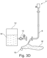
- FIGS 3A-3D show schematically the different steps of an embodiment for pressurizing the supply line 6.
- Figure 3A shows a water supply in the form of a reservoir 12 filled with water W and with coupled thereto a pressure pump 13 and a pressure gauge 14, which is preferably provided with a logger for tracking the measurements during a time period.
- a ball 15 with a positive buoyancy is placed via coupling 7 into supply line 6.
- the pressure pump 13 and reservoir 12 are coupled to supply line 6 so that supply line 6 can be filled with water.
- the ball 15, floating on the water will be pressed upward through supply line 6 toward foam generator 4.
- pressure pump 13 and reservoir 12 can be uncoupled from supply line 6 again, so that the water W flows out of supply line 6. As the water W flows out, the ball 15 will also leave supply line 6 again, after which supply line 6 and foam generator 4 can be put back into operation.
- Figure 4 shows a schematic representation of a variant of a combination for performing the method according to the invention.
- components corresponding with the combination shown in figures 3A-3D are designated with the same reference numerals.
- a filling pump 32 with a water reservoir 12 is further connected to the shut-off valve 31.
- a standard fire truck, particularly a fire engine, can usually be used as the filling pump 32 with water reservoir 12.
- shut-off valve 31 Further provided between shut-off valve 31 and coupling 7 is the pressure gauge 14 with logger and a pressure pump 33, which can draw in water W from a second reservoir 34.
- supply line 6 is filled with water W using filling pump 32, wherein the ball 15 is pressed upward to the foam generator 4.
- shut-off valve 31 is closed and filling pump 32 with reservoir 12 can be uncoupled. Pressurizing of the supply line 6 can then take place with the pressure pump 33 and the water W from the second reservoir 34.
Landscapes
- Physics & Mathematics (AREA)
- General Physics & Mathematics (AREA)
- Health & Medical Sciences (AREA)
- Public Health (AREA)
- Business, Economics & Management (AREA)
- Emergency Management (AREA)
- Fire-Extinguishing By Fire Departments, And Fire-Extinguishing Equipment And Control Thereof (AREA)
Abstract
- providing a water supply and a pressure pump;
- providing a ball with a positive buoyancy;
- placing the ball in the second end of the supply line;
- connecting the water supply and pressure pump to the second end of the supply line;
- filling the supply line with water from the water supply, wherein the ball is entrained through the supply line by the water and comes to lie sealingly against the restriction in the feed opening of the foam generator;
- bringing the water in the supply line to a desired test pressure with the pressure pump;
- draining the supply line via the second end after a desired testing time has passed, wherein the ball leaves the supply line along with the water.
Description
- The invention relates to a method for pressurizing a supply line, which is coupled with a first end to the feed opening of a foam generator, which foam generator is arranged close to an upper side of a storage or transfer tank, wherein a restriction is provided in the feed opening of the foam generator and wherein the first end of the supply line lies higher than the second end of the supply line.
- Storage or transfer tanks, which are used for storage of chemicals and fuels, or K1, K2 and K3 fluids, are provided with a fire extinguishing system. Such a fire extinguishing system is provided with, among other things, foam generators which can arrange a foam layer on the fluid in the tank and so enable any fire to be extinguished. In the event of a fire a mixture of water and foaming agent is pumped via a supply line into the feed opening of the foam generator. A restriction is provided in the feed opening and an air supply is present directly downstream of the restriction, so that mixing of the mixture of water and foaming agent with drawn-in air takes place owing to the venturi effect and foam is so formed.
- It is important for a fire extinguishing system to be inspected periodically. The supply lines of the foam generators must here be pressurized to a desired test pressure. When the test pressure does not drop to any considerable extent during a desired testing time, and a visual inspection of the supply line shows no defects, it can be concluded that the supply lines still meet requirements.
- In order to enable the supply lines to be pressurized the foam generator must usually be uncoupled from the supply line in order to be able to close the first end of the supply line, or a closure must be arranged in the foam generator itself, for instance a closure of the restriction by means of a blank flange. With such modifications there is a risk that removing the arranged closure again after pressurizing of the supply line will be forgotten. When use must then be made of the foam generator in the event of a fire, it will no longer function.
- It is now an object of the invention to reduce or even obviate the above stated drawbacks. This object is achieved according to the invention with a method according to the preamble, which comprises the steps of:
- providing a water supply and a pressure pump;
- providing a ball with a positive buoyancy;
- placing the ball in the second end of the supply line;
- connecting the water supply and pressure pump to the second end of the supply line;
- filling the supply line with water from the water supply, wherein the ball is entrained through the supply line by the water and comes to lie sealingly against the restriction in the feed opening of the foam generator;
- bringing the water in the supply line to a desired test pressure with the pressure pump;
- draining the supply line via the second end after a desired testing time has passed, wherein the ball leaves the supply line along with the water.
- Because the ball is entrained with the water when the supply line is filled, the ball will come to lie against the restriction in the feed opening of the foam generator, whereby the restriction is closed. This then makes it possible to increase the pressure in the supply line and so pressurize the supply line. The advantage is that no modifications whatsoever need to be carried out on the foam generator.
- After the supply line has been pressurized, the water can flow back out of the supply line and the ball will return with it and exit the supply line. In this way a supply line can be pressurized quickly, after which the fire extinguishing system can be put back into operation. The water and the ball can either flow freely out of the supply line, or the ball can be received in a non-return valve housing which is arranged between the second end and the pressure pump.
- A non-return valve, which prevents the fluid from the tank from flowing away again via the supply line in the event that the storage or transfer tank is overfilled, is often provided at the second end of the supply line. When performing the method according to the invention, the non-return valve must be temporarily removed beforehand in order to enable the supply line to be drained. The housing for the non-return valve forms a catch for the ball and furthermore a simple connection point for the pressure gauge.
- In an embodiment of the method according to the invention the ball has a diameter at atmospheric pressure which is smaller than the inner diameter of the supply line.
- This ensures that the ball does not become stuck in the supply line, particularly when the water runs back out of the line after the pressurizing.
- In a further embodiment of the method according to the invention the ball has a diameter at atmospheric pressure which is greater than the main dimension, for instance the diameter, of the restriction in the feed opening of the foam generator. The restriction will usually have a round form, wherein the main dimension is the diameter. In the case however that the restriction is for instance square, the ball will need to have a diameter which is at least equal to the diagonal of the square restriction in order to enable a good seal.
- In a highly preferred embodiment of the method according to the invention the ball has a diameter at atmospheric pressure which is greater than half the sum of the inner diameter of the supply line and the main dimension, for instance the diameter, of the restriction in the feed opening of the foam generator. With such a diameter of the ball it will immediately close the restriction when the ball, floating on the water in the supply line, reaches the restriction. With a smaller diameter, there is a chance that the ball does not close the restriction immediately, whereby some water will still be able to end up in the foam generator.
- The invention further relates to a combination comprising:
- a storage or transfer tank with a foam generator arranged close to the upper side of the storage or transfer tank for the purpose of generating foam from a water and foaming agent mixture and air, and a supply line which is coupled with a first end to the feed opening of the foam generator, wherein the second end of the supply line is arranged close to the base of the storage or transfer tank and wherein a restriction is provided in the feed opening of the foam generator,
- a water supply and a pressure pump connected to the second end of the supply line; and
- a ball with a positive buoyancy positioned in the supply line;
- It is also possible to provide a separate filling pump with water supply and separate pressure pump with water supply so that, after the supply line has been filled, the filling pump with water supply can already be uncoupled before testing of the supply line with the pressure pump begins.
- These and other features of the invention are further elucidated with reference to the accompanying drawings.
-
Figure 1 shows a perspective view of a storage or transfer tank with a foam generator arranged close to the upper side thereof. -
Figure 2 shows a cross-section of the foam generator according tofigure 1 . -
Figures 3A-3D show four steps of an embodiment of the method according to the invention. -
Figure 4 shows a schematic representation of a variant of a combination for performing the method according to the invention. -
Figure 1 shows a storage or transfer tank 1 in perspective view. The storage or transfer tank 1 is placed on a tank mound 2, which is usually provided in a tank pit, which in turn is surrounded by a tank dike, wall of sheet piling. Arranged on the upper edge of tank 1 is arailing 3, as is afoam generator 4.Foam generator 4 has a discharge line 5 which discharges generated foam in tank 1 and asupply line 6 wherebyfoam generator 4 can be provided with a mixture of water and foaming agent. Provided on the underside ofsupply line 6 is aclosable coupling 7 to which a fire hose can for instance be coupled. -
Figure 2 shows a cross-section offoam generator 4.Foam generator 4 has afoam chamber 8 with anupward conduit 9, which is coupled to supplyline 6, on the underside. Arranged in the coupling betweensupply line 6 andupward conduit 9 is arestriction 10 with immediately downstream thereof, inupward conduit 9, anair supply 11. When the mixture of water and foam mixture is pumped through therestriction 10 viasupply line 6, air will be entrained viaair supply 11 and foam generated as a result of the venturi effect, which foam will end up in thefoam chamber 8. Usually provided on the discharge line 5 whenfoam generator 4 is not in use is a rupture disc which closes discharge line 5 and prevents harmful, flammable and explosive vapours from being able to find their way into the atmosphere from the tank. During use offoam generator 4 the rupture disc will break immediately due to the pressure of the foam and clear a path, so that the foam is able to flow away via discharge line 5 and end up in transfer tank 1. -
Figures 3A-3D show schematically the different steps of an embodiment for pressurizing thesupply line 6. -
Figure 3A shows a water supply in the form of areservoir 12 filled with water W and with coupled thereto apressure pump 13 and apressure gauge 14, which is preferably provided with a logger for tracking the measurements during a time period. In the first step aball 15 with a positive buoyancy is placed viacoupling 7 intosupply line 6. - In the subsequent step (see
figure 3B ) thepressure pump 13 andreservoir 12 are coupled to supplyline 6 so thatsupply line 6 can be filled with water. For this purpose theball 15, floating on the water, will be pressed upward throughsupply line 6 towardfoam generator 4. - Finally, ball 15 (see
figure 3C ) will be pressed against therestriction 10 by the water W, wherebyfoam generator 4 is closed off from the supply line. The pressure can then be raised to a desired test pressure insupply line 6 withpressure pump 13, which pressure can be read on thepressure gauge 14. - After a desired testing time,
pressure pump 13 andreservoir 12 can be uncoupled fromsupply line 6 again, so that the water W flows out ofsupply line 6. As the water W flows out, theball 15 will also leavesupply line 6 again, after whichsupply line 6 andfoam generator 4 can be put back into operation. -
Figure 4 shows a schematic representation of a variant of a combination for performing the method according to the invention. Infigure 4 components corresponding with the combination shown infigures 3A-3D are designated with the same reference numerals. - A
housing 30 for a non-return valve, in which a shut-offvalve 31 is schematically arranged, is arranged on thecoupling 7 ofsupply line 6 for thefoam generator 4. Via thishousing 30 theball 15 can be introduced into thesupply line 6. A fillingpump 32 with awater reservoir 12 is further connected to the shut-offvalve 31. A standard fire truck, particularly a fire engine, can usually be used as the fillingpump 32 withwater reservoir 12. - Further provided between shut-off
valve 31 andcoupling 7 is thepressure gauge 14 with logger and apressure pump 33, which can draw in water W from asecond reservoir 34. - According to the method,
supply line 6 is filled with water W using fillingpump 32, wherein theball 15 is pressed upward to thefoam generator 4. Whensupply line 6 is completely filled, shut-offvalve 31 is closed and fillingpump 32 withreservoir 12 can be uncoupled. Pressurizing of thesupply line 6 can then take place with thepressure pump 33 and the water W from thesecond reservoir 34. The advantage is that a fire engine need for instance not remain hooked up during the pressurizing and testing ofsupply line 6.
Claims (5)
- Method for pressurizing a supply line, which is coupled with a first end to the feed opening of a foam generator, which foam generators arranged close to an upper side of a storage or transfer tank, wherein a restriction is provided in the feed opening of the foam generator and wherein the first end of the supply line lies higher than the second end of the supply line, which method comprises the steps of:- providing a water supply and a pressure pump;- providing a ball with a positive buoyancy;- placing the ball in the second end of the supply line;- connecting the water supply and pressure pump to the second end of the supply line;- filling the supply line with water from the water supply, wherein the ball is entrained through the supply line by the water and comes to lie sealingly against the restriction in the feed opening of the foam generator;- bringing the water in the supply line to a desired test pressure with the pressure pump;- draining the supply line via the second end after a desired testing time has passed, wherein the ball leaves the supply line along with the water.
- Method according to claim 1, wherein the ball has a diameter at atmospheric pressure which is smaller than the inner diameter of the supply line.
- Method according to claim 2, wherein the ball has a diameter at atmospheric pressure which is greater than the main dimension, for instance the diameter, of the restriction in the feed opening of the foam generator.
- Method according to claim 3, wherein the ball has a diameter at atmospheric pressure which is greater than half the sum of the inner diameter of the supply line and the main dimension, for instance the diameter, of the restriction in the feed opening of the foam generator.
- Combination comprising:- a storage or transfer tank with a foam generator arranged close to the upper side of the storage or transfer tank for the purpose of generating foam from a water and foaming agent mixture and air, and a supply line which is coupled with a first end to the feed opening of the foam generator, wherein the second end of the supply line is arranged close to the base of the storage or transfer tank and wherein a restriction is provided in the feed opening of the foam generator,- a water supply and a pressure pump connected to the second end of the supply line; and- a ball with a positive buoyancy positioned in the supply line;wherein the supply line is filled with water from the water supply and the ball is pressed sealingly against the restriction by the buoyancy.
Applications Claiming Priority (1)
| Application Number | Priority Date | Filing Date | Title |
|---|---|---|---|
| NL2035781A NL2035781B1 (en) | 2023-09-12 | 2023-09-12 | Method for pressurizing a supply line of a foam generator |
Publications (3)
| Publication Number | Publication Date |
|---|---|
| EP4524540A1 true EP4524540A1 (en) | 2025-03-19 |
| EP4524540B1 EP4524540B1 (en) | 2026-01-28 |
| EP4524540C0 EP4524540C0 (en) | 2026-01-28 |
Family
ID=90653281
Family Applications (1)
| Application Number | Title | Priority Date | Filing Date |
|---|---|---|---|
| EP24193789.5A Active EP4524540B1 (en) | 2023-09-12 | 2024-08-09 | Method for pressurizing a supply line of a foam generator |
Country Status (2)
| Country | Link |
|---|---|
| EP (1) | EP4524540B1 (en) |
| NL (1) | NL2035781B1 (en) |
Citations (3)
| Publication number | Priority date | Publication date | Assignee | Title |
|---|---|---|---|---|
| US20050189027A1 (en) * | 2004-02-27 | 2005-09-01 | Markham Allen R. | Plumbing test plug and method |
| EP3163143A1 (en) * | 2015-11-02 | 2017-05-03 | Ford Global Technologies, LLC | A removable passage closure plug |
| US9700746B2 (en) * | 2009-04-16 | 2017-07-11 | South-Tek Systems, LLC | Gas purging valve for fire protection system |
-
2023
- 2023-09-12 NL NL2035781A patent/NL2035781B1/en active
-
2024
- 2024-08-09 EP EP24193789.5A patent/EP4524540B1/en active Active
Patent Citations (3)
| Publication number | Priority date | Publication date | Assignee | Title |
|---|---|---|---|---|
| US20050189027A1 (en) * | 2004-02-27 | 2005-09-01 | Markham Allen R. | Plumbing test plug and method |
| US9700746B2 (en) * | 2009-04-16 | 2017-07-11 | South-Tek Systems, LLC | Gas purging valve for fire protection system |
| EP3163143A1 (en) * | 2015-11-02 | 2017-05-03 | Ford Global Technologies, LLC | A removable passage closure plug |
Also Published As
| Publication number | Publication date |
|---|---|
| EP4524540B1 (en) | 2026-01-28 |
| EP4524540C0 (en) | 2026-01-28 |
| NL2035781B1 (en) | 2025-03-17 |
Similar Documents
| Publication | Publication Date | Title |
|---|---|---|
| US5727603A (en) | Method for preventing fuel spillage | |
| US3910102A (en) | Liquid volumetric line leak testing apparatus and method | |
| US9346662B2 (en) | Fuel delivery system and method | |
| US20110030839A1 (en) | Apparatus and method for fuelling an aircraft tank system | |
| CZ20012960A3 (en) | Method of testing volatile liquid vapor sampling systems | |
| JPH0521589B2 (en) | ||
| JP5221039B2 (en) | Secondary containment leak prevention and detection system and method in a fuel dispenser | |
| US6247492B1 (en) | Overfill protection for fuel tanks | |
| US20070289664A1 (en) | Fuel overflow prevention device | |
| EP4524540B1 (en) | Method for pressurizing a supply line of a foam generator | |
| CN204461702U (en) | A kind of device for detecting sealability of pressure vessel peculiar to vessel | |
| US9453583B1 (en) | Vent for tank | |
| AU2017200674B2 (en) | Breather check valve | |
| US6739174B2 (en) | NoFoam system for testing a FOAM delivery system on a vehicle | |
| US4074734A (en) | Liquid delivery system | |
| US11034571B2 (en) | Test port for fuel dispenser | |
| US8104327B1 (en) | Leak detection method for a primary containment system | |
| US6715373B2 (en) | NoFoam system for testing a foam delivery system on a vehicle | |
| WO2015197455A1 (en) | Device for reducing dangers during release of combustible gases and highly inflammable vapors | |
| US7290457B2 (en) | NoFoam system for testing a foam delivery system on a vehicle | |
| US11649155B2 (en) | Test port for fuel dispenser | |
| JPH08261866A (en) | Pulsating water pressure tester | |
| US1825280A (en) | Method for locating points of leakage in conduits | |
| CN208405823U (en) | Movable foam liquid generating device | |
| US20220074821A1 (en) | Test facility for carrying out a fire stress test on a water flow valve |
Legal Events
| Date | Code | Title | Description |
|---|---|---|---|
| PUAI | Public reference made under article 153(3) epc to a published international application that has entered the european phase |
Free format text: ORIGINAL CODE: 0009012 |
|
| STAA | Information on the status of an ep patent application or granted ep patent |
Free format text: STATUS: THE APPLICATION HAS BEEN PUBLISHED |
|
| AK | Designated contracting states |
Kind code of ref document: A1 Designated state(s): AL AT BE BG CH CY CZ DE DK EE ES FI FR GB GR HR HU IE IS IT LI LT LU LV MC ME MK MT NL NO PL PT RO RS SE SI SK SM TR |
|
| STAA | Information on the status of an ep patent application or granted ep patent |
Free format text: STATUS: REQUEST FOR EXAMINATION WAS MADE |
|
| GRAP | Despatch of communication of intention to grant a patent |
Free format text: ORIGINAL CODE: EPIDOSNIGR1 |
|
| STAA | Information on the status of an ep patent application or granted ep patent |
Free format text: STATUS: GRANT OF PATENT IS INTENDED |
|
| 17P | Request for examination filed |
Effective date: 20250905 |
|
| INTG | Intention to grant announced |
Effective date: 20250924 |
|
| GRAS | Grant fee paid |
Free format text: ORIGINAL CODE: EPIDOSNIGR3 |
|
| GRAA | (expected) grant |
Free format text: ORIGINAL CODE: 0009210 |
|
| STAA | Information on the status of an ep patent application or granted ep patent |
Free format text: STATUS: THE PATENT HAS BEEN GRANTED |
|
| AK | Designated contracting states |
Kind code of ref document: B1 Designated state(s): AL AT BE BG CH CY CZ DE DK EE ES FI FR GB GR HR HU IE IS IT LI LT LU LV MC ME MK MT NL NO PL PT RO RS SE SI SK SM TR |
|
| REG | Reference to a national code |
Ref country code: CH Ref legal event code: F10 Free format text: ST27 STATUS EVENT CODE: U-0-0-F10-F00 (AS PROVIDED BY THE NATIONAL OFFICE) Effective date: 20260128 Ref country code: GB Ref legal event code: FG4D |
|
| REG | Reference to a national code |
Ref country code: DE Ref legal event code: R096 Ref document number: 602024002297 Country of ref document: DE |
|
| REG | Reference to a national code |
Ref country code: IE Ref legal event code: FG4D |
|
| U01 | Request for unitary effect filed |
Effective date: 20260128 |
|
| U07 | Unitary effect registered |
Designated state(s): AT BE BG DE DK EE FI FR IT LT LU LV MT NL PT RO SE SI Effective date: 20260204 |