EP4524527A1 - Infrared sensors - Google Patents
Infrared sensors Download PDFInfo
- Publication number
- EP4524527A1 EP4524527A1 EP24196133.3A EP24196133A EP4524527A1 EP 4524527 A1 EP4524527 A1 EP 4524527A1 EP 24196133 A EP24196133 A EP 24196133A EP 4524527 A1 EP4524527 A1 EP 4524527A1
- Authority
- EP
- European Patent Office
- Prior art keywords
- detection module
- infrared detection
- power signal
- temperature
- module
- Prior art date
- Legal status (The legal status is an assumption and is not a legal conclusion. Google has not performed a legal analysis and makes no representation as to the accuracy of the status listed.)
- Pending
Links
Images


Classifications
-
- G—PHYSICS
- G01—MEASURING; TESTING
- G01J—MEASUREMENT OF INTENSITY, VELOCITY, SPECTRAL CONTENT, POLARISATION, PHASE OR PULSE CHARACTERISTICS OF INFRARED, VISIBLE OR ULTRAVIOLET LIGHT; COLORIMETRY; RADIATION PYROMETRY
- G01J5/00—Radiation pyrometry, e.g. infrared or optical thermometry
- G01J5/007—Radiation pyrometry, e.g. infrared or optical thermometry for earth observation
-
- G—PHYSICS
- G01—MEASURING; TESTING
- G01J—MEASUREMENT OF INTENSITY, VELOCITY, SPECTRAL CONTENT, POLARISATION, PHASE OR PULSE CHARACTERISTICS OF INFRARED, VISIBLE OR ULTRAVIOLET LIGHT; COLORIMETRY; RADIATION PYROMETRY
- G01J5/00—Radiation pyrometry, e.g. infrared or optical thermometry
- G01J5/02—Constructional details
- G01J5/06—Arrangements for eliminating effects of disturbing radiation; Arrangements for compensating changes in sensitivity
- G01J5/061—Arrangements for eliminating effects of disturbing radiation; Arrangements for compensating changes in sensitivity by controlling the temperature of the apparatus or parts thereof, e.g. using cooling means or thermostats
-
- G—PHYSICS
- G01—MEASURING; TESTING
- G01J—MEASUREMENT OF INTENSITY, VELOCITY, SPECTRAL CONTENT, POLARISATION, PHASE OR PULSE CHARACTERISTICS OF INFRARED, VISIBLE OR ULTRAVIOLET LIGHT; COLORIMETRY; RADIATION PYROMETRY
- G01J3/00—Spectrometry; Spectrophotometry; Monochromators; Measuring colours
- G01J3/02—Details
- G01J3/0286—Constructional arrangements for compensating for fluctuations caused by temperature, humidity or pressure, or using cooling or temperature stabilization of parts of the device; Controlling the atmosphere inside a spectrometer, e.g. vacuum
-
- G—PHYSICS
- G01—MEASURING; TESTING
- G01J—MEASUREMENT OF INTENSITY, VELOCITY, SPECTRAL CONTENT, POLARISATION, PHASE OR PULSE CHARACTERISTICS OF INFRARED, VISIBLE OR ULTRAVIOLET LIGHT; COLORIMETRY; RADIATION PYROMETRY
- G01J3/00—Spectrometry; Spectrophotometry; Monochromators; Measuring colours
- G01J3/02—Details
- G01J3/0291—Housings; Spectrometer accessories; Spatial arrangement of elements, e.g. folded path arrangements
-
- G—PHYSICS
- G01—MEASURING; TESTING
- G01J—MEASUREMENT OF INTENSITY, VELOCITY, SPECTRAL CONTENT, POLARISATION, PHASE OR PULSE CHARACTERISTICS OF INFRARED, VISIBLE OR ULTRAVIOLET LIGHT; COLORIMETRY; RADIATION PYROMETRY
- G01J5/00—Radiation pyrometry, e.g. infrared or optical thermometry
- G01J5/02—Constructional details
- G01J5/025—Interfacing a pyrometer to an external device or network; User interface
-
- G—PHYSICS
- G01—MEASURING; TESTING
- G01J—MEASUREMENT OF INTENSITY, VELOCITY, SPECTRAL CONTENT, POLARISATION, PHASE OR PULSE CHARACTERISTICS OF INFRARED, VISIBLE OR ULTRAVIOLET LIGHT; COLORIMETRY; RADIATION PYROMETRY
- G01J5/00—Radiation pyrometry, e.g. infrared or optical thermometry
- G01J5/02—Constructional details
- G01J5/04—Casings
-
- G—PHYSICS
- G01—MEASURING; TESTING
- G01J—MEASUREMENT OF INTENSITY, VELOCITY, SPECTRAL CONTENT, POLARISATION, PHASE OR PULSE CHARACTERISTICS OF INFRARED, VISIBLE OR ULTRAVIOLET LIGHT; COLORIMETRY; RADIATION PYROMETRY
- G01J5/00—Radiation pyrometry, e.g. infrared or optical thermometry
- G01J5/02—Constructional details
- G01J5/04—Casings
- G01J5/041—Mountings in enclosures or in a particular environment
-
- G—PHYSICS
- G01—MEASURING; TESTING
- G01J—MEASUREMENT OF INTENSITY, VELOCITY, SPECTRAL CONTENT, POLARISATION, PHASE OR PULSE CHARACTERISTICS OF INFRARED, VISIBLE OR ULTRAVIOLET LIGHT; COLORIMETRY; RADIATION PYROMETRY
- G01J5/00—Radiation pyrometry, e.g. infrared or optical thermometry
- G01J5/02—Constructional details
- G01J5/06—Arrangements for eliminating effects of disturbing radiation; Arrangements for compensating changes in sensitivity
- G01J5/064—Ambient temperature sensor; Housing temperature sensor; Constructional details thereof
-
- G—PHYSICS
- G01—MEASURING; TESTING
- G01J—MEASUREMENT OF INTENSITY, VELOCITY, SPECTRAL CONTENT, POLARISATION, PHASE OR PULSE CHARACTERISTICS OF INFRARED, VISIBLE OR ULTRAVIOLET LIGHT; COLORIMETRY; RADIATION PYROMETRY
- G01J5/00—Radiation pyrometry, e.g. infrared or optical thermometry
- G01J5/10—Radiation pyrometry, e.g. infrared or optical thermometry using electric radiation detectors
-
- G—PHYSICS
- G01—MEASURING; TESTING
- G01J—MEASUREMENT OF INTENSITY, VELOCITY, SPECTRAL CONTENT, POLARISATION, PHASE OR PULSE CHARACTERISTICS OF INFRARED, VISIBLE OR ULTRAVIOLET LIGHT; COLORIMETRY; RADIATION PYROMETRY
- G01J5/00—Radiation pyrometry, e.g. infrared or optical thermometry
- G01J2005/0077—Imaging
-
- G—PHYSICS
- G01—MEASURING; TESTING
- G01J—MEASUREMENT OF INTENSITY, VELOCITY, SPECTRAL CONTENT, POLARISATION, PHASE OR PULSE CHARACTERISTICS OF INFRARED, VISIBLE OR ULTRAVIOLET LIGHT; COLORIMETRY; RADIATION PYROMETRY
- G01J5/00—Radiation pyrometry, e.g. infrared or optical thermometry
- G01J5/02—Constructional details
- G01J5/06—Arrangements for eliminating effects of disturbing radiation; Arrangements for compensating changes in sensitivity
- G01J5/061—Arrangements for eliminating effects of disturbing radiation; Arrangements for compensating changes in sensitivity by controlling the temperature of the apparatus or parts thereof, e.g. using cooling means or thermostats
- G01J2005/063—Heating; Thermostating
-
- G—PHYSICS
- G01—MEASURING; TESTING
- G01J—MEASUREMENT OF INTENSITY, VELOCITY, SPECTRAL CONTENT, POLARISATION, PHASE OR PULSE CHARACTERISTICS OF INFRARED, VISIBLE OR ULTRAVIOLET LIGHT; COLORIMETRY; RADIATION PYROMETRY
- G01J5/00—Radiation pyrometry, e.g. infrared or optical thermometry
- G01J5/10—Radiation pyrometry, e.g. infrared or optical thermometry using electric radiation detectors
- G01J2005/106—Arrays
Definitions
- the present disclosure generally relates to sensors, and more particularly, to infrared sensors for measuring infrared radiation in, but not limited to, extreme, dynamic temperature environments.
- Aircrafts can install infrared sensors to detect infrared radiation.
- an aircraft can use an infrared sensor to determine crop health, ocean temperature, and other climate related measurements. Because aircrafts typically fly in various environmental conditions, it can be difficult for an infrared sensor to accurately measure radiometric properties. For example, as the ambient temperature increases or decreases as an aircraft descends or ascends, a radiometric calibration of the infrared sensor can become unstable. As a result, the infrared sensor may not be able to accurately measure subtle changes in sea surface temperatures that can affect ocean life that are sensitive to small temperature changes.
- the present application is directed to improving infrared radiance measurement accuracy.
- An infrared detection module and a thermoelectric module may be included in a relatively small sensor housing for use at remote sensing locations or in labs, factories, aircrafts, etc.
- the infrared detection module is a focal plane array.
- the thermoelectric module is proximate to the infrared detection module within the sensor housing such that the thermoelectric module can provide a heating effect or a cooling effect to the infrared detection module.
- the thermoelectric module can act as a variable-resistant load that can provide electrical heating or cooling to the infrared detection module based on a proximity of the variable-resistant load to the infrared detection module.
- the infrared detection module can include a temperature monitor that is configured to monitor a temperature of the infrared detection module and generate a corresponding temperature reading.
- the temperature reading can be transmitted to a sensor processor associated with the infrared sensor through a communication port, such as RS-485.
- the sensor processor can be located a fair distance from the sensor housing.
- the sensor processor can be located in a sensor processor housing that is external to the sensor housing.
- the sensor processor can determine whether (or how) to adjust the temperature of the infrared detection module. For example, the sensor processor can determine whether to increase the temperature of the infrared detection module, decrease the temperature of the infrared detection module, or maintain the temperature of the infrared detection module at the current temperature.
- the sensor processor can adjust the temperature of the infrared detection module by generating a pulse-width modulated power signal and filtering it to provide direct current power to the thermoelectric module that is proximate to the infrared detection module.
- the sensor processor can generate a pulse-width modulated signal having a first polarity such that when the direct current power signal is provided to the thermoelectric module, the thermoelectric module provides a cooling effect to the infrared detection module.
- the sensor processor can generate a pulse-width modulated power signal having a second polarity such that when the direct current power signal is provided to the thermoelectric module, the thermoelectric module provides a heating effect to the infrared detection module.
- thermoelectric module cools or heats the infrared detection module is based on the ratio of the pulse-width to the pulse repeat interval of the pulse-width modulated power signal, which when filtered, provides a direct current voltage at the same ratio to the maximum available voltage.
- Calibration e.g., radiometric calibration
- the sensor processor can generate pulse-width modulated power signals such that, when the direct current power signals are provided to the thermoelectric module, the thermoelectric modules provides electrical heating and cooling to the infrared detection module to maintain the temperature of the infrared detection module at the designated temperature.
- the techniques described herein can be used to provide thermal control to the infrared detection module such that the temperature of the infrared detection module is maintained near the target temperature.
- the radiometric calibration of the infrared sensor is stabilized and the infrared sensor can generate accurate readings.
- the system includes a sensor housing and a sensor processor external to the sensor housing.
- the sensor housing includes an infrared detection module and a thermoelectric module proximate to the infrared detection module.
- the infrared detection module is configured to detect infrared radiation of a scene and generate a measurement associated with the infrared radiation of the scene.
- the thermoelectric module is configured to provide thermal control to the infrared detection module based on a modulated power signal. An accuracy of the measurement is based on the thermal control provided to the infrared detection module.
- the sensor processor is configured to transmit a power signal to the infrared detection module and transmit a direct current power signal to the thermoelectric module. The direct current power signal is based on the modulated power signal.
- the method includes detecting, by an infrared detection module, infrared radiation of a scene.
- the method also includes generating, by the infrared detection module, a measurement associated with the infrared radiation of the scene.
- the method also includes providing, by a thermoelectric module proximate to the infrared detection module, thermal control to the infrared detection module based on a modulated power signal. An accuracy of the measurement is based on the thermal control provided to the infrared detection module.
- a sensor housing includes the thermoelectric module and the infrared detection module.
- a sensor processor external to the sensor housing, transmits a power signal to the infrared detection module and transmits a direct current power signal to the thermoelectric module. The direct current power signal is based on the modulated power signal.
- a non-transitory computer-readable medium having stored thereon instructions is disclosed.
- the instructions when executed by a sensor processor external to a sensor housing, cause the sensor processor to perform operations.
- the operations include transmitting a power signal to an infrared detection module within the sensor housing.
- the power signal causes the infrared detection module to detect infrared radiation of a scene and generate a measurement associated with the infrared radiation of the scene.
- the operations also include transmitting a direct current power signal to a thermoelectric module within the sensor housing.
- the direct current power signal causes the thermoelectric module to provide thermal control to the infrared detection module. An accuracy of the measurement is based on the thermal control provided to the infrared detection module.
- the thermoelectric module is proximate to the infrared detection module.
- the distinguishing letter "A" is used.
- the reference number 190 may be used without a distinguishing letter.
- an ordinal term e.g., "first,” “second,” “third,” etc.
- an element such as a structure, a component, an operation, etc.
- the term “set” refers to a grouping of one or more elements
- the term “plurality” refers to multiple elements.
- the system 100 includes a sensor processor housing 110 and a sensor housing 130.
- the sensor processor housing 110 is located in an aircraft interior, such as an interior region or cabin of the aircraft 400 of Figure 4 .
- the sensor housing 130 is located on an aircraft exterior, such as proximate an exterior surface of the aircraft 400 of Figure 4 .
- the sensor processor housing 110 includes a sensor processor 114.
- the sensor housing 130 includes an infrared detection module 132 and a thermoelectric module 134 that is proximate to the infrared detection module 132.
- a thermal path between the thermoelectric module 134 and the infrared detection module 132 can be comprised of a thermally conductive alloy structure.
- An outer polymer of the thermal path can provide insulation.
- the infrared detection module 132 includes an infrared radiation detector 140, a temperature monitor 142, and a control module 144.
- the components within the sensor housing 130 can be configured to communicate with the sensor processor 114 using one or more cables.
- a single cable can be used to facilitate data communication between the sensor processor 114 and the infrared detection module 132.
- a single cable can be coupled to an interface 190A of the sensor processor 114 and to an interface 190B of the infrared detection module 132.
- data can be transferred from the infrared detection module 132 to the sensor processor 114, and data can be transferred from the sensor processor 114 to the infrared detection module 132.
- the communication port corresponds to RS-485.
- the sensor processor 114 includes a thermal control unit 116, a calibration unit 118, and a sensor control unit 120.
- the sensor control unit 120 includes a memory 112.
- the memory 112 can correspond to a non-transitory computer-readable medium that includes instructions 113 that are executable by the sensor control unit 120 to perform the operations disclosed herein.
- the sensor control unit 120 can be configured to transmit a power signal 160 (e.g., a direct current power signal) to the infrared detection module 132 to provide power to the infrared detection module 132.
- Data and commands 151 can be exchanged between the sensor control unit 120 and the interface 190A.
- the infrared detection module 132 can be configured to detect infrared radiation 138 of a scene.
- the infrared detection module 132 can detect the infrared radiation 138 of a scene surrounding the aircraft 400 when the aircraft 400 is in flight.
- the infrared radiation detector 140 can detect the infrared radiation 138 of the scene.
- the sensor housing 130 can include a small window 102 that enables the infrared radiation detector 140 to detect the infrared radiation 138 of the scene.
- the infrared radiation detector 140 (or the infrared detection module 132) corresponds to a focal plane array that detects the infrared radiation 138.
- the infrared detection module 132 can also be configured to generate a measurement 146 (e.g., radiometric values) associated with infrared radiation 138.
- the infrared radiation detector 140 can generate the measurement 146 (e.g., a raw measurement) associated with the infrared radiation 138.
- the measurement 146 is provided to the control module 144 and is transmitted to the sensor processor 114 as part of a signal 170.
- the control module 144 transmits the measurement 146 to the sensor processor 114 as part of the signal 170.
- the measurement 146 is provided to the calibration unit 118.
- the calibration unit 118 can calibrate the measurement 146 to generate an infrared radiance measurement 147 that is provided to a host system.
- the temperature of the infrared detection module 132 can change based on environmental temperature effects 108.
- An accuracy of the measurement 146 can be based on a temperature of the infrared detection module 132.
- the temperature of the infrared detection module 132 should be maintained at a particular temperature.
- the particular temperature can correspond to 25 degrees Celsius.
- the measurement 146 can be relatively accurate if the particular temperature of the infrared detection module 132 is within a relatively small range of temperatures. It should be understood that the temperatures and/or temperature ranges are merely for illustrative purposes and should not be construed as limiting.
- the infrared detection module 132 can be calibrated such that the measurements 146 are relatively accurate at other temperatures and/or temperature ranges.
- direct current power signals 163 can be provided to the thermoelectric module 134 to provide thermal control 152 within the sensor housing 130.
- the temperature monitor 142 can be configured to monitor the temperature of the infrared detection module 132 and generate a temperature reading 150 that is indicative of the temperature. The temperature reading 150 is provided to the control module 144 and is transmitted to the sensor processor 114 as part of the signal 170.
- the control module 144 transmits the temperature reading 150 to the sensor processor 114 as part of the signal 170.
- the temperature reading 150 is provided to the thermal control unit 116.
- the thermal control unit 116 can be configured to generate a modulated power signal 162 that is filtered into a direct current power signal 163.
- a polarity of the modulated power signal 162 can be used to provide thermal control 152 (e.g., a cooling effect or a heating effect) to the thermoelectric module 134.
- the thermal control unit 116 can generate a modulated power signal 162 having a first polarity.
- thermoelectric module 134 can provide the cooling effect as the thermal control 152 in response to receiving the direct current power signal 163 based on the modulated power signal 162 having the first polarity.
- the thermal control unit 116 can generate a modulated power signal 162 having a second polarity.
- the thermoelectric module 134 can provide the heating effect as the thermal control 152 in response to receiving the direct current power signal 163 based on the modulated power signal 162 having the second polarity.
- the magnitude at which the thermoelectric module 134 cools or heats the infrared detection module 132 is based on the pulse-width modulated power signal 162 and filter, and thus the magnitude of the direct current power signal 163.
- the thermal control unit 116 can be configured to transmit the direct current power signal 163 to the thermoelectric module 134.
- the thermoelectric module 134 can be configured to receive the direct current power signal 163 and provide thermal control 152 to the infrared detection module 132 based on the direct current power signal 163.
- the thermoelectric module 134 acts as a variable-resistant load that provides the cooling effect or the heating effect based on the polarity of the modulated power signal 162.
- the thermoelectric module 134 can be configured to provide the cooling effect to the infrared detection module 132 in response to the modulated power signal 162 having the first polarity.
- the thermoelectric module 134 can be configured to provide the heating effect to the infrared detection module 132 in response to the modulated power signal 162 having the second polarity.
- the thermoelectric module 134 can be configured to provide the heating effect or the cooling effect to the infrared detection module 132 to maintain a particular temperature of the infrared detection module 132. As described above, in some non-limiting examples of the particular temperature is 25 degrees Celsius.
- the system 100 of Figure 1 improves calibration of the infrared detection module 132 by maintaining the temperature of the infrared detection module 132 at a target temperature (e.g., 25 degrees Celsius).
- a target temperature e.g. 25 degrees Celsius
- the sensor processor 114 can generate the direct current power signal 163 and provide the direct current power signal 163 to the thermoelectric module 134.
- the thermoelectric module 134 can provide heating or cooling to the infrared detection module 132 to maintain the temperature of the infrared detection module 132 at the target temperature 164.
- a calibration metric associated with the infrared detection module 132 is stabilized based on the thermal control 152 provided to the infrared detection module 132 via the thermoelectric module 134.
- the sensor processor 114 can continue to receive temperature readings 150 from the infrared detection module 132 and provide direct current power signals 163 (based on the temperature readings 150) to the thermoelectric module 134 to temperature control the infrared detection module 132.
- the sensor processor 114 is illustrated, in accordance with an example. As described above, the sensor processor 114 is separated from the infrared detection module 132, which in turn, enables the sensor housing 130 to have a relatively small size.
- the sensor processor 114 can be relatively small in size. According to some examples, the sensor processor 114 can have a width of 5.5 inches (14 cm) or approximately 5.5 inches (14 cm), a length of 7.5 inches (19.1 cm) or approximately 7.5 inches (19.1 cm), and a height of 3 inches (7.6 cm) or approximately 3 inches (7.6 cm). It should be understood that the above dimensions are merely for illustrative purposes and should not be construed as limiting. In other examples, the sensor processor 114 can have alternative dimensions and/or shapes. According to some examples, the sensor processor 114 can be relatively light in weight. In some non-limiting examples, the sensor processor 114 can weigh less than 4 pounds (1.8 kg).
- the sensor processor 114 can include a plurality of interfaces.
- the sensor processor 114 can include the interface 190A (e.g., the RS-485 port), an Ethernet port 202, and a power port 204.
- the interface 190A can be used to facilitate data transmission between the sensor processor 114 and the infrared detection module 132.
- the Ethernet port 202 can enable the sensor processor 114 to communicate with the host system.
- the Ethernet port 202 can be used to facilitate data transmission between the host system and the sensor processor 114 via an Ethernet cable.
- the power port 204 can enable the sensor processor 114 to receive power.
- a power cable can be coupled to the power port 204 and to a host system such that the sensor processor 114 receives power from the host system.
- the power cable can be coupled to the power port 204 and to another power source such that the sensor processor 114 receives power from another power source.
- the sensor processor 114 depicted in Figure 2 enables greater flexibility for the infrared detection module 132.
- the sensor housing 130 can have a relatively small size, which enables the infrared detection module 132 to fit in more locations, as further depicted in Figure 4 .
- the infrared detection module 132 is illustrated, in accordance with an example. As described above, the infrared detection module 132 is separated from the sensor processor 114, which in turn, enables the sensor housing 130 to have a relatively small size.
- the infrared detection module 132 can be relatively small in size. According to some examples, the infrared detection module 132 can have a width of 1.7 inches (4.3 cm) or approximately 1.7 inches (4.3 cm), a length of 1.7 inches (4.3 cm) or approximately 1.7 inches (4.3 cm), and a height of 1.55 inches (3.94 cm) or approximately 1.55 inches (3.94 cm). It should be understood that the above dimensions are merely for illustrative purposes and should not be construed as limiting. In other examples, the infrared detection module 132 can have alternative dimensions and/or shapes. According to some examples, the infrared detection module 132 can be relatively light in weight. In some non-limiting examples, the infrared detection module 132 can weigh 0.5 pounds (0.27 kg) or approximately 0.5 pounds (0.27 kg).
- thermoelectric module 134 can provide electrical heating and cooling to the infrared detection module 132.
- the infrared detection module 132 measurement can undergo radiometric calibration.
- a measurement associated with the infrared detection module 132 is stabilized based on the thermal control 152 provided to the infrared detection module 132 via the thermoelectric module 134.
- an aircraft 400 is illustrated, in accordance with an example.
- the aircraft 400 includes external components and an outer mold line 406.
- the infrared detection module 132 and an associated sensor housing, such as the sensor housing 130 can be coupled to external components or to the outer mold line 406 of the aircraft 400, such as the belly of the aircraft 400.
- Figure 5 illustrates a flow chart of a method 500, according to an example.
- the method 500 can be performed by the system 100 of Figure 1 .
- the method 500 includes detecting, by an infrared detection module, infrared radiation of a scene, at block 502.
- an infrared detection module detects infrared radiation 138 of a scene.
- the method 500 includes generating, by the infrared detection module, a measurement associated with the infrared radiation of the scene, at block 504.
- the infrared detection module 132 generates the measurement 146 associated with the infrared radiation 138 of the scene.
- the method 500 also includes providing, by a thermoelectric module proximate to the infrared detection module, thermal control to the infrared detection module based on a filtered modulated power signal, at block 506.
- An accuracy of the measurement is based on the thermal control provided to the infrared detection module.
- the sensor housing includes the thermoelectric module and the infrared detection module.
- the thermoelectric module 134 provides thermal control 152 to the infrared detection module 132 based on the modulated power signal 162 used to generate the direct current power signal 163.
- An accuracy of the measurement 146 is based on the thermal control 152 provided to the infrared detection module 132.
- the sensor housing 130 includes the thermoelectric module 134 and the infrared detection module 132.
- a sensor processor external to the housing, transmits a power signal to the infrared detection module and transmits a direct current power signal to the thermoelectric module.
- the direct current power signal is based on the modulated power signal.
- the sensor processor 114 external to the sensor housing 130, transmits the power signal 160 to the infrared detection module 132 and transmits the direct current power signal 163 (based on the modulated power signal 162) to the thermoelectric module 134.
- the method 500 includes monitoring, by a temperature monitor of the infrared detection module, a temperature of the infrared detection module.
- the temperature monitor 142 monitors the temperature 148 of the infrared detection module 132.
- the method 500 can also include transmitting, by the temperature monitor, a temperature reading to the sensor processor.
- the temperature reading is indicative of the temperature of the infrared detection module.
- the temperature monitor 142 transmits the temperature reading 150 to the sensor processor 114.
- the temperature reading 150 is indicative of the temperature 148 of the infrared detection module 132.
- the sensor processor 114 generates the modulated power signal 162 based, at least in part, on the temperature reading 150.
- providing the thermal control 152 to the infrared detection module 132 includes providing a cooling effect to the infrared detection module 132 in response to the modulated power signal 162 having a first polarity.
- providing the thermal control 152 to the infrared detection module 132 includes providing a heating effect to the infrared detection module 132 in response to the modulated power signal 162 having a second polarity.
- providing the thermal control 152 to the infrared detection module 132 includes providing a heating effect or a cooling effect to the infrared detection module 132 to maintain a particular temperature of the infrared detection module 132. In some non-limiting examples, the particular temperature correspond to 25 degrees Celsius.
- the method 500 of Figure 5 improves calibration of the infrared detection module 132 measurement by maintaining the temperature of the infrared detection module 132 at a target temperature (e.g., 25 degrees Celsius).
- a target temperature e.g. 25 degrees Celsius
- the sensor processor 114 can generate the direct current power signal 163 (e.g., a filtered version of the modulated power signal 162) and provide the direct current power signal 163 to the thermoelectric module 134.
- the thermoelectric module 134 Based on the polarity and magnitude of the direct current power signal 163, the thermoelectric module 134 can provide heating or cooling to the infrared detection module 132 to maintain the temperature of the infrared detection module 132 at the target temperature.
- a measurement associated with the infrared detection module 132 is stabilized based on the thermal control 152 provided to the infrared detection module 132 via the thermoelectric module 134.
- a system (100) comprising: a sensor housing (130) comprising: an infrared detection module (132) configured to: detect infrared radiation (138) of a scene; and generate a measurement (146) associated with the infrared radiation (138) of the scene; and a thermoelectric module (134) proximate to the infrared detection module (132), the thermoelectric module (134) configured to provide thermal control (152) to the infrared detection module (132) based on a modulated power signal (162), wherein an accuracy of the measurement (146) is based on the thermal control (152) provided to the infrared detection module (132); and a sensor processor (114) external to the sensor housing (130), the sensor processor (114) configured to: transmit a power signal (160) to the infrared detection module (132); and transmit a direct current power signal (163) to the thermoelectric module (134), wherein the direct current power signal (163) is based on the modulated power signal (162).
- Clause 2 The system (100) of Clause 1, wherein the infrared detection module (132) comprises a temperature monitor (142) that is configured to: monitor a temperature of the infrared detection module (132); and transmit a temperature reading (150) to the sensor processor (114), wherein the temperature reading (150) is indicative of the temperature of the infrared detection module (132), wherein the sensor processor (114) is configured to generate the modulated power signal (162) based, at least in part, on the temperature reading (150).
- a temperature monitor 142
- the sensor processor (114) is configured to generate the modulated power signal (162) based, at least in part, on the temperature reading (150).
- thermoelectric module (134) is configured to provide a cooling effect to the infrared detection module (132) in response to the modulated power signal (162) having a first polarity.
- thermoelectric module (134) is configured to provide a heating effect to the infrared detection module (132) in response to the modulated power signal (162) having a second polarity.
- thermoelectric module (134) is configured to provide a heating effect or a cooling effect to the infrared detection module (132) to maintain a particular temperature of the infrared detection module (132).
- thermoelectric module (134) acts as a variable-resistant load.
- Clause 7 The system (100) of any of Clauses 1 to 6, further comprising a cable to facilitate data communication between the sensor processor (114) and the infrared detection module (132).
- Clause 8 The system (100) of any of Clauses 1 to 7, wherein the infrared detection module (132) includes a focal plane array.
- Clause 9 The system (100) of any of Clauses 1 to 8, wherein the sensor processor is configured to communicate with a host system.
- a method (500) comprising: detecting (502), by an infrared detection module (132), infrared radiation (138) of a scene; generating (504), by the infrared detection module (132), a measurement associated with the infrared radiation (138) of the scene; and providing (506), by a thermoelectric module (134) proximate to the infrared detection module (132), thermal control (152) to the infrared detection module (132) based on a modulated power signal (162), wherein an accuracy of the measurement is based on the thermal control (152) provided to the infrared detection module (132), and wherein a sensor housing (130) comprises the thermoelectric module (134) and the infrared detection module (132), wherein a sensor processor (114), external to the sensor housing (130), transmits a power signal (160) to the infrared detection module (132) and transmits a direct current power signal (163) to the thermoelectric module (134), wherein the direct current power signal (163) is based
- Clause 11 The method (500) of Clause 10, further comprising: monitoring, by a temperature monitor (142) of the infrared detection module (132), a temperature of the infrared detection module (132); and transmitting, by the temperature monitor (142), a temperature reading (150) to the sensor processor (114), wherein the temperature reading (150) is indicative of the temperature of the infrared detection module (132), wherein the sensor processor (114) generates the modulated power signal (162) based, at least in part, on the temperature reading (150).
- Clause 12 The method (500) of Clause 10 or 11, wherein providing the thermal control (152) to the infrared detection module (132) comprises providing a cooling effect to the infrared detection module (132) in response to the modulated power signal (162) having a first polarity.
- Clause 13 The method (500) of any of Clauses 10 to 12, wherein providing the thermal control (152) to the infrared detection module (132) comprises providing a heating effect to the infrared detection module (132) in response to the modulated power signal (162) having a second polarity.
- Clause 14 The method (500) of any of Clauses 10 to 13, wherein providing the thermal control (152) to the infrared detection module (132) comprises providing a heating effect or a cooling effect to the infrared detection module (132) to maintain a particular temperature of the infrared detection module (132).
- thermoelectric module (134) acts as a variable-resistant load.
- Clause 16 The method (500) of any of Clauses 10 to 15, wherein the infrared detection module (132) includes a focal plane array.
- Clause 17 A computer program comprising computer program instructions that, when executed by one of more computer processors, cause the one or more computer processors to perform the method of any of Clauses 10 to 16.
- Clause 18 A non-transitory computer-readable medium having stored thereon the computer program of Clause 17.
- a non-transitory computer-readable medium comprising instructions that, when executed by a sensor processor (114) external to a sensor housing (130), cause the sensor processor (114) to perform operations comprising: transmitting a power signal (160) to an infrared detection module (132) within the sensor housing (130), the power signal (160) causing the infrared detection module (132) to: detect infrared radiation (138) of a scene; and generate a measurement associated with the infrared radiation (138) of the scene; and transmitting a direct current power signal (163) to a thermoelectric module (134) within the sensor housing (130), the direct current power signal (163) causing the thermoelectric module (134) to provide thermal control (152) to the infrared detection module (132), wherein an accuracy of the measurement is based on the thermal control (152) provided to the infrared detection module (132), and wherein the thermoelectric module (134) is proximate to the infrared detection module (132).
- thermoelectric module (134) acts as a variable-resistant load.
- Clause 21 The non-transitory computer-readable medium of Clause 19 or 20, wherein the infrared detection module (132) includes a focal plane array.
- Clause 22 The non-transitory computer-readable medium of any of Clauses 19 to 21, wherein providing the thermal control (152) to the infrared detection module (132) comprises providing a heating effect or a cooling effect to the infrared detection module (132) to maintain a particular temperature of the infrared detection module (132).
- a computer program comprising computer program instructions that, when executed by a sensor processor (114) external to a sensor housing (130), cause the sensor processor (114) to perform operations comprising: transmitting a power signal (160) to an infrared detection module (132) within the sensor housing (130), the power signal (160) causing the infrared detection module (132) to: detect infrared radiation (138) of a scene; and generate a measurement associated with the infrared radiation (138) of the scene; and transmitting a direct current power signal (163) to a thermoelectric module (134) within the sensor housing (130), the direct current power signal (163) causing the thermoelectric module (134) to provide thermal control (152) to the infrared detection module (132), wherein an accuracy of the measurement is based on the thermal control (152) provided to the infrared detection module (132), and wherein the thermoelectric module (134) is proximate to the infrared detection module (132).
- thermoelectric module (134) acts as a variable-resistant load.
- Clause 25 The computer program of Clause 23 or 24, wherein the infrared detection module (132) includes a focal plane array.
- Clause 26 The computer program of any of Clauses 23 to 25, wherein providing the thermal control (152) to the infrared detection module (132) comprises providing a heating effect or a cooling effect to the infrared detection module (132) to maintain a particular temperature of the infrared detection module (132).
- system can be a vehicle other than an aircraft without departing from the essence of the present disclosure.
- instances in this specification where one element is "coupled" to another element can include direct and indirect coupling.
- Direct coupling can be defined as one element coupled to and in some contact with another element.
- Indirect coupling can be defined as coupling between two elements not in direct contact with each other, but having one or more additional elements between the coupled elements.
- securing one element to another element can include direct securing and indirect securing.
- adjacent does not necessarily denote contact. For example, one element can be adjacent another element without being in contact with that element.
- a system, apparatus, structure, article, element, component, or hardware “configured to” perform a specified function is indeed capable of performing the specified function without any alteration, rather than merely having potential to perform the specified function after further modification.
- the system, apparatus, structure, article, element, component, or hardware “configured to” perform a specified function is specifically selected, created, implemented, utilized, programmed, and/or designed for the purpose of performing the specified function.
- "configured to” denotes existing characteristics of a system, apparatus, structure, article, element, component, or hardware which enable the system, apparatus, structure, article, element, component, or hardware to perform the specified function without further modification.
- a system, apparatus, structure, article, element, component, or hardware described as being “configured to” perform a particular function may additionally or alternatively be described as being “adapted to” and/or as being “operative to” perform that function.
- first, second, etc. are used herein merely as labels, and are not intended to impose ordinal, positional, or hierarchical requirements on the items to which these terms refer. Moreover, reference to, e.g., a “second” item does not require or preclude the existence of, e.g., a "first” or lower-numbered item, and/or, e.g., a "third" or higher-numbered item.
Landscapes
- Physics & Mathematics (AREA)
- Spectroscopy & Molecular Physics (AREA)
- General Physics & Mathematics (AREA)
- Engineering & Computer Science (AREA)
- Human Computer Interaction (AREA)
- Life Sciences & Earth Sciences (AREA)
- Environmental & Geological Engineering (AREA)
- General Life Sciences & Earth Sciences (AREA)
- Geology (AREA)
- Photometry And Measurement Of Optical Pulse Characteristics (AREA)
Abstract
A system includes a sensor housing and a sensor processor external to the sensor housing. The sensor housing includes an infrared detection module and a thermoelectric module proximate to the infrared detection module. The infrared detection module is configured to detect infrared radiation of a scene and generate a measurement associated with the infrared radiation. The thermoelectric module is configured to provide thermal control to the infrared detection module based on a modulated power signal. An accuracy of the measurement is based on the thermal control provided to the infrared detection module. The sensor processor is configured to transmit a power signal to the infrared detection module and transmit a direct current power signal to the thermoelectric module. The direct current power signal is based on the modulated power signal.
Description
- The present disclosure generally relates to sensors, and more particularly, to infrared sensors for measuring infrared radiation in, but not limited to, extreme, dynamic temperature environments.
- This background description is provided for the purpose of generally presenting the context of the disclosure. Unless otherwise indicated herein, material described in this section is neither expressly nor impliedly admitted to be prior art to the present disclosure or the appended claims.
- Aircrafts can install infrared sensors to detect infrared radiation. As non-limiting examples, an aircraft can use an infrared sensor to determine crop health, ocean temperature, and other climate related measurements. Because aircrafts typically fly in various environmental conditions, it can be difficult for an infrared sensor to accurately measure radiometric properties. For example, as the ambient temperature increases or decreases as an aircraft descends or ascends, a radiometric calibration of the infrared sensor can become unstable. As a result, the infrared sensor may not be able to accurately measure subtle changes in sea surface temperatures that can affect ocean life that are sensitive to small temperature changes.
- The present application is directed to improving infrared radiance measurement accuracy. An infrared detection module and a thermoelectric module may be included in a relatively small sensor housing for use at remote sensing locations or in labs, factories, aircrafts, etc. In some examples, the infrared detection module is a focal plane array. The thermoelectric module is proximate to the infrared detection module within the sensor housing such that the thermoelectric module can provide a heating effect or a cooling effect to the infrared detection module. For example, the thermoelectric module can act as a variable-resistant load that can provide electrical heating or cooling to the infrared detection module based on a proximity of the variable-resistant load to the infrared detection module. The infrared detection module can include a temperature monitor that is configured to monitor a temperature of the infrared detection module and generate a corresponding temperature reading. The temperature reading can be transmitted to a sensor processor associated with the infrared sensor through a communication port, such as RS-485. To reduce the size of the sensor housing, instead of locating the sensor processor within the sensor housing, the sensor processor can be located a fair distance from the sensor housing. As a non-limiting example, the sensor processor can be located in a sensor processor housing that is external to the sensor housing.
- Based on the temperature reading, the sensor processor can determine whether (or how) to adjust the temperature of the infrared detection module. For example, the sensor processor can determine whether to increase the temperature of the infrared detection module, decrease the temperature of the infrared detection module, or maintain the temperature of the infrared detection module at the current temperature. The sensor processor can adjust the temperature of the infrared detection module by generating a pulse-width modulated power signal and filtering it to provide direct current power to the thermoelectric module that is proximate to the infrared detection module. For example, to decrease the temperature of the infrared detection module, the sensor processor can generate a pulse-width modulated signal having a first polarity such that when the direct current power signal is provided to the thermoelectric module, the thermoelectric module provides a cooling effect to the infrared detection module. Alternatively, to increase the temperature of the infrared detection module, the sensor processor can generate a pulse-width modulated power signal having a second polarity such that when the direct current power signal is provided to the thermoelectric module, the thermoelectric module provides a heating effect to the infrared detection module. The magnitude at which the thermoelectric module cools or heats the infrared detection module is based on the ratio of the pulse-width to the pulse repeat interval of the pulse-width modulated power signal, which when filtered, provides a direct current voltage at the same ratio to the maximum available voltage.
- Calibration (e.g., radiometric calibration) of the infrared sensor can be maintained or substantially maintained by maintaining the temperature of the infrared detection module at a designated target temperature. Thus, using the feedback associated with the temperature reading described above, the sensor processor can generate pulse-width modulated power signals such that, when the direct current power signals are provided to the thermoelectric module, the thermoelectric modules provides electrical heating and cooling to the infrared detection module to maintain the temperature of the infrared detection module at the designated temperature. Thus, when the infrared detection module is in low temperature environments, the techniques described herein can be used to provide thermal control to the infrared detection module such that the temperature of the infrared detection module is maintained near the target temperature. As a result, the radiometric calibration of the infrared sensor is stabilized and the infrared sensor can generate accurate readings.
- There is described herein a system. The system includes a sensor housing and a sensor processor external to the sensor housing. The sensor housing includes an infrared detection module and a thermoelectric module proximate to the infrared detection module. The infrared detection module is configured to detect infrared radiation of a scene and generate a measurement associated with the infrared radiation of the scene. The thermoelectric module is configured to provide thermal control to the infrared detection module based on a modulated power signal. An accuracy of the measurement is based on the thermal control provided to the infrared detection module. The sensor processor is configured to transmit a power signal to the infrared detection module and transmit a direct current power signal to the thermoelectric module. The direct current power signal is based on the modulated power signal.
- There is described herein a method. The method includes detecting, by an infrared detection module, infrared radiation of a scene. The method also includes generating, by the infrared detection module, a measurement associated with the infrared radiation of the scene. The method also includes providing, by a thermoelectric module proximate to the infrared detection module, thermal control to the infrared detection module based on a modulated power signal. An accuracy of the measurement is based on the thermal control provided to the infrared detection module. A sensor housing includes the thermoelectric module and the infrared detection module. A sensor processor, external to the sensor housing, transmits a power signal to the infrared detection module and transmits a direct current power signal to the thermoelectric module. The direct current power signal is based on the modulated power signal.
- There is described herein a non-transitory computer-readable medium having stored thereon instructions is disclosed. The instructions, when executed by a sensor processor external to a sensor housing, cause the sensor processor to perform operations. The operations include transmitting a power signal to an infrared detection module within the sensor housing. The power signal causes the infrared detection module to detect infrared radiation of a scene and generate a measurement associated with the infrared radiation of the scene. The operations also include transmitting a direct current power signal to a thermoelectric module within the sensor housing. The direct current power signal causes the thermoelectric module to provide thermal control to the infrared detection module. An accuracy of the measurement is based on the thermal control provided to the infrared detection module. The thermoelectric module is proximate to the infrared detection module.
- The foregoing summary is illustrative only and is not intended to be in any way limiting. In addition to the illustrative examples and features described above, further examples and features will become apparent by reference to the figures and the following detailed description.
- A more complete understanding of examples of the present application may be derived by referring to the detailed description and claims when considered in conjunction with the following figures, wherein like reference numbers may refer to similar elements throughout the figures. The figures are provided to facilitate understanding of the disclosure without limiting the breadth, scope, scale, or applicability of the disclosure. The drawings are not necessarily made to scale.
-
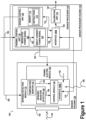
Figure 1 illustrates a system that is operable to provide thermal control to an infrared detection module associated with an infrared sensor; -
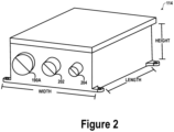
Figure 2 illustrates a sensor processor; -
Figure 3 illustrate an infrared sensor; -
Figure 4 illustrates an aircraft; and -
Figure 5 is a flowchart. - The figures and the following description illustrate specific examples. It will be appreciated that those skilled in the art will be able to devise various arrangements that, although not explicitly described or shown herein, embody the principles described herein and are included within the scope of the claims that follow this description. Furthermore, any examples described herein are intended to aid in understanding the principles of the disclosure and are to be construed as being without limitation. As a result, this disclosure is not limited to the specific examples described below, but by the claims.
- Particular examples are described herein with reference to the drawings. In the description, common features may be designated by common reference numbers throughout the drawings. In some drawings, multiple instances of a particular type of feature are used. Although these features are physically and/or logically distinct, the same reference number is used for each, and the different instances are distinguished by addition of a letter to the reference number. When the features as a group or a type are referred to herein (e.g., when no particular one of the features is being referenced), the reference number is used without a distinguishing letter. However, when one particular feature of multiple features of the same type is referred to herein, the reference number is used with the distinguishing letter. For example, referring to
Figure 1 , interfaces are illustrated and associated with reference number 190. When referring to a particular one of the interfaces, such as theinterface 190A, the distinguishing letter "A" is used. However, when referring to any arbitrary one of the interfaces or to the interfaces as a group, the reference number 190 may be used without a distinguishing letter. - As used herein, various terminology is used for the purpose of describing particular examples only and is not intended to be limiting. For example, the singular forms "a," "an," and "the" are intended to include the plural forms as well, unless the context clearly indicates otherwise. Further, the terms "comprise," "comprises," and "comprising" are used interchangeably with "include," "includes," or "including." Additionally, the term "wherein" is used interchangeably with the term "where." As used herein, "exemplary" indicates an example and should not be construed as limiting or as indicating a preference or a preferred example. As used herein, an ordinal term (e.g., "first," "second," "third," etc.) used to modify an element, such as a structure, a component, an operation, etc., does not by itself indicate any priority or order of the element with respect to another element, but rather merely distinguishes the element from another element having a same name (but for use of the ordinal term). As used herein, the term "set" refers to a grouping of one or more elements, and the term "plurality" refers to multiple elements.
- Referring to
Figure 1 , asystem 100 that is operable to provide thermal control to an infrared detection module associated with an infrared sensor is illustrated, in accordance with an example. Thesystem 100 includes a sensor processor housing 110 and a sensor housing 130. According to some examples, the sensor processor housing 110 is located in an aircraft interior, such as an interior region or cabin of theaircraft 400 ofFigure 4 . According to some examples, the sensor housing 130 is located on an aircraft exterior, such as proximate an exterior surface of theaircraft 400 ofFigure 4 . - The sensor processor housing 110 includes a
sensor processor 114. The sensor housing 130 includes aninfrared detection module 132 and athermoelectric module 134 that is proximate to theinfrared detection module 132. In some examples, a thermal path between thethermoelectric module 134 and theinfrared detection module 132 can be comprised of a thermally conductive alloy structure. An outer polymer of the thermal path can provide insulation. - The
infrared detection module 132 includes aninfrared radiation detector 140, a temperature monitor 142, and acontrol module 144. The components within the sensor housing 130 can be configured to communicate with thesensor processor 114 using one or more cables. According to some examples, a single cable can be used to facilitate data communication between thesensor processor 114 and theinfrared detection module 132. For example, a single cable can be coupled to aninterface 190A of thesensor processor 114 and to aninterface 190B of theinfrared detection module 132. Using the single cable and the interfaces 190, data can be transferred from theinfrared detection module 132 to thesensor processor 114, and data can be transferred from thesensor processor 114 to theinfrared detection module 132. According to some examples, the communication port corresponds to RS-485. - The
sensor processor 114 includes athermal control unit 116, acalibration unit 118, and asensor control unit 120. Thesensor control unit 120 includes amemory 112. Thememory 112 can correspond to a non-transitory computer-readable medium that includesinstructions 113 that are executable by thesensor control unit 120 to perform the operations disclosed herein. For example, thesensor control unit 120 can be configured to transmit a power signal 160 (e.g., a direct current power signal) to theinfrared detection module 132 to provide power to theinfrared detection module 132. Data and commands 151 can be exchanged between thesensor control unit 120 and theinterface 190A. - In response to receiving the
power signal 160, theinfrared detection module 132 can be configured to detectinfrared radiation 138 of a scene. For example, if the sensor housing 130 is installed on anaircraft 400, theinfrared detection module 132 can detect theinfrared radiation 138 of a scene surrounding theaircraft 400 when theaircraft 400 is in flight. To illustrate, inFigure 1 , theinfrared radiation detector 140 can detect theinfrared radiation 138 of the scene. For example, the sensor housing 130 can include asmall window 102 that enables theinfrared radiation detector 140 to detect theinfrared radiation 138 of the scene. In some examples, the infrared radiation detector 140 (or the infrared detection module 132) corresponds to a focal plane array that detects theinfrared radiation 138. - The
infrared detection module 132 can also be configured to generate a measurement 146 (e.g., radiometric values) associated withinfrared radiation 138. For example, theinfrared radiation detector 140 can generate the measurement 146 (e.g., a raw measurement) associated with theinfrared radiation 138. Themeasurement 146 is provided to thecontrol module 144 and is transmitted to thesensor processor 114 as part of asignal 170. For example, using theinterface 190B, thecontrol module 144 transmits themeasurement 146 to thesensor processor 114 as part of thesignal 170. When thesignal 170 is received by theinterface 190A of thesensor processor 114, themeasurement 146 is provided to thecalibration unit 118. Thecalibration unit 118 can calibrate themeasurement 146 to generate aninfrared radiance measurement 147 that is provided to a host system. - In some scenarios, the temperature of the
infrared detection module 132 can change based on environmental temperature effects 108. An accuracy of themeasurement 146 can be based on a temperature of theinfrared detection module 132. For example, to generate relativelyaccurate measurements 146, the temperature of theinfrared detection module 132 should be maintained at a particular temperature. In some non-limiting examples, the particular temperature can correspond to 25 degrees Celsius. In some other non-limiting examples, themeasurement 146 can be relatively accurate if the particular temperature of theinfrared detection module 132 is within a relatively small range of temperatures. It should be understood that the temperatures and/or temperature ranges are merely for illustrative purposes and should not be construed as limiting. In other examples, theinfrared detection module 132 can be calibrated such that themeasurements 146 are relatively accurate at other temperatures and/or temperature ranges. - To ensure that the temperature of the
infrared detection module 132 is maintained at a level that enables theinfrared detection module 132 to generateaccurate measurements 146 for theinfrared radiation 138, based on the temperature of theinfrared detection module 132, direct current power signals 163 can be provided to thethermoelectric module 134 to providethermal control 152 within the sensor housing 130. To illustrate, the temperature monitor 142 can be configured to monitor the temperature of theinfrared detection module 132 and generate a temperature reading 150 that is indicative of the temperature. Thetemperature reading 150 is provided to thecontrol module 144 and is transmitted to thesensor processor 114 as part of thesignal 170. For example, using theinterface 190B, thecontrol module 144 transmits the temperature reading 150 to thesensor processor 114 as part of thesignal 170. When thesignal 170 is received by theinterface 190A of thesensor processor 114, the temperature reading 150 is provided to thethermal control unit 116. - In response to receiving the temperature reading 150, the
thermal control unit 116 can be configured to generate a modulatedpower signal 162 that is filtered into a directcurrent power signal 163. As described below, a polarity of the modulatedpower signal 162 can be used to provide thermal control 152 (e.g., a cooling effect or a heating effect) to thethermoelectric module 134. Thus, if the temperature reading 150 indicates that the temperature of theinfrared detection module 132 is too hot (e.g., greater than a target temperature 164), thethermal control unit 116 can generate a modulatedpower signal 162 having a first polarity. As described below, thethermoelectric module 134 can provide the cooling effect as thethermal control 152 in response to receiving the directcurrent power signal 163 based on the modulatedpower signal 162 having the first polarity. Alternatively, if the temperature reading 150 indicates that the temperature of theinfrared detection module 132 is too cold (e.g., less than the target temperature 164), thethermal control unit 116 can generate a modulatedpower signal 162 having a second polarity. As described below, thethermoelectric module 134 can provide the heating effect as thethermal control 152 in response to receiving the directcurrent power signal 163 based on the modulatedpower signal 162 having the second polarity. The magnitude at which thethermoelectric module 134 cools or heats theinfrared detection module 132 is based on the pulse-width modulatedpower signal 162 and filter, and thus the magnitude of the directcurrent power signal 163. Thethermal control unit 116 can be configured to transmit the directcurrent power signal 163 to thethermoelectric module 134. - The
thermoelectric module 134 can be configured to receive the directcurrent power signal 163 and providethermal control 152 to theinfrared detection module 132 based on the directcurrent power signal 163. For example, in some examples, thethermoelectric module 134 acts as a variable-resistant load that provides the cooling effect or the heating effect based on the polarity of the modulatedpower signal 162. According some examples, to provide thethermal control 152 to theinfrared detection module 132, thethermoelectric module 134 can be configured to provide the cooling effect to theinfrared detection module 132 in response to the modulatedpower signal 162 having the first polarity. According to other examples, to provide thethermal control 152 to theinfrared detection module 132, thethermoelectric module 134 can be configured to provide the heating effect to theinfrared detection module 132 in response to the modulatedpower signal 162 having the second polarity. Thus, to provide thethermal control 152 to theinfrared detection module 132, thethermoelectric module 134 can be configured to provide the heating effect or the cooling effect to theinfrared detection module 132 to maintain a particular temperature of theinfrared detection module 132. As described above, in some non-limiting examples of the particular temperature is 25 degrees Celsius. - The
system 100 ofFigure 1 improves calibration of theinfrared detection module 132 by maintaining the temperature of theinfrared detection module 132 at a target temperature (e.g., 25 degrees Celsius). For example, based on the temperature reading 150 from theinfrared detection module 132, thesensor processor 114 can generate the directcurrent power signal 163 and provide the directcurrent power signal 163 to thethermoelectric module 134. Based on the polarity of the modulatedpower signal 162 filtered to generate a magnitude of the directcurrent power signal 163, thethermoelectric module 134 can provide heating or cooling to theinfrared detection module 132 to maintain the temperature of theinfrared detection module 132 at thetarget temperature 164. As a result, a calibration metric associated with theinfrared detection module 132 is stabilized based on thethermal control 152 provided to theinfrared detection module 132 via thethermoelectric module 134. - The
sensor processor 114 can continue to receivetemperature readings 150 from theinfrared detection module 132 and provide direct current power signals 163 (based on the temperature readings 150) to thethermoelectric module 134 to temperature control theinfrared detection module 132. - Referring to
Figure 2 , thesensor processor 114 is illustrated, in accordance with an example. As described above, thesensor processor 114 is separated from theinfrared detection module 132, which in turn, enables the sensor housing 130 to have a relatively small size. - The
sensor processor 114 can be relatively small in size. According to some examples, thesensor processor 114 can have a width of 5.5 inches (14 cm) or approximately 5.5 inches (14 cm), a length of 7.5 inches (19.1 cm) or approximately 7.5 inches (19.1 cm), and a height of 3 inches (7.6 cm) or approximately 3 inches (7.6 cm). It should be understood that the above dimensions are merely for illustrative purposes and should not be construed as limiting. In other examples, thesensor processor 114 can have alternative dimensions and/or shapes. According to some examples, thesensor processor 114 can be relatively light in weight. In some non-limiting examples, thesensor processor 114 can weigh less than 4 pounds (1.8 kg). - As illustrated in
Figure 2 , thesensor processor 114 can include a plurality of interfaces. For example, thesensor processor 114 can include theinterface 190A (e.g., the RS-485 port), anEthernet port 202, and apower port 204. As described with respect toFigure 1 , theinterface 190A can be used to facilitate data transmission between thesensor processor 114 and theinfrared detection module 132. - The
Ethernet port 202 can enable thesensor processor 114 to communicate with the host system. For example, theEthernet port 202 can be used to facilitate data transmission between the host system and thesensor processor 114 via an Ethernet cable. Thepower port 204 can enable thesensor processor 114 to receive power. According to some examples, a power cable can be coupled to thepower port 204 and to a host system such that thesensor processor 114 receives power from the host system. According to other examples, the power cable can be coupled to thepower port 204 and to another power source such that thesensor processor 114 receives power from another power source. - The
sensor processor 114 depicted inFigure 2 enables greater flexibility for theinfrared detection module 132. For example, by separating thesensor processor 114 from the sensor housing 130 (e.g., separating thesensor processor 114 from the infrared detection module 132), the sensor housing 130 can have a relatively small size, which enables theinfrared detection module 132 to fit in more locations, as further depicted inFigure 4 . - Referring to
Figure 3 , theinfrared detection module 132 is illustrated, in accordance with an example. As described above, theinfrared detection module 132 is separated from thesensor processor 114, which in turn, enables the sensor housing 130 to have a relatively small size. - The
infrared detection module 132 can be relatively small in size. According to some examples, theinfrared detection module 132 can have a width of 1.7 inches (4.3 cm) or approximately 1.7 inches (4.3 cm), a length of 1.7 inches (4.3 cm) or approximately 1.7 inches (4.3 cm), and a height of 1.55 inches (3.94 cm) or approximately 1.55 inches (3.94 cm). It should be understood that the above dimensions are merely for illustrative purposes and should not be construed as limiting. In other examples, theinfrared detection module 132 can have alternative dimensions and/or shapes. According to some examples, theinfrared detection module 132 can be relatively light in weight. In some non-limiting examples, theinfrared detection module 132 can weigh 0.5 pounds (0.27 kg) or approximately 0.5 pounds (0.27 kg). - As described above, the
thermoelectric module 134 can provide electrical heating and cooling to theinfrared detection module 132. Theinfrared detection module 132 measurement can undergo radiometric calibration. As described with respect toFigure 1 , a measurement associated with theinfrared detection module 132 is stabilized based on thethermal control 152 provided to theinfrared detection module 132 via thethermoelectric module 134. - Referring to
Figure 4 , anaircraft 400 is illustrated, in accordance with an example. Among other things, theaircraft 400 includes external components and anouter mold line 406. As illustrated inFigure 4 , theinfrared detection module 132 and an associated sensor housing, such as the sensor housing 130, can be coupled to external components or to theouter mold line 406 of theaircraft 400, such as the belly of theaircraft 400. -
Figure 5 illustrates a flow chart of amethod 500, according to an example. Themethod 500 can be performed by thesystem 100 ofFigure 1 . - The
method 500 includes detecting, by an infrared detection module, infrared radiation of a scene, atblock 502. For example, referring toFigure 1 , theinfrared detection module 132 detectsinfrared radiation 138 of a scene. - The
method 500 includes generating, by the infrared detection module, a measurement associated with the infrared radiation of the scene, atblock 504. For example, referring toFigure 1 , theinfrared detection module 132 generates themeasurement 146 associated with theinfrared radiation 138 of the scene. - The
method 500 also includes providing, by a thermoelectric module proximate to the infrared detection module, thermal control to the infrared detection module based on a filtered modulated power signal, atblock 506. An accuracy of the measurement is based on the thermal control provided to the infrared detection module. The sensor housing includes the thermoelectric module and the infrared detection module. For example, referring toFigure 1 , thethermoelectric module 134 providesthermal control 152 to theinfrared detection module 132 based on the modulatedpower signal 162 used to generate the directcurrent power signal 163. An accuracy of themeasurement 146 is based on thethermal control 152 provided to theinfrared detection module 132. The sensor housing 130 includes thethermoelectric module 134 and theinfrared detection module 132. - In the
method 500, a sensor processor, external to the housing, transmits a power signal to the infrared detection module and transmits a direct current power signal to the thermoelectric module. The direct current power signal is based on the modulated power signal. For example, referring toFigure 1 , thesensor processor 114, external to the sensor housing 130, transmits thepower signal 160 to theinfrared detection module 132 and transmits the direct current power signal 163 (based on the modulated power signal 162) to thethermoelectric module 134. - According to some examples, the
method 500 includes monitoring, by a temperature monitor of the infrared detection module, a temperature of the infrared detection module. For example, referring toFigure 1 , the temperature monitor 142 monitors the temperature 148 of theinfrared detection module 132. Themethod 500 can also include transmitting, by the temperature monitor, a temperature reading to the sensor processor. The temperature reading is indicative of the temperature of the infrared detection module. For example, referring toFigure 1 , the temperature monitor 142 transmits the temperature reading 150 to thesensor processor 114. Thetemperature reading 150 is indicative of the temperature 148 of theinfrared detection module 132. Thesensor processor 114 generates the modulatedpower signal 162 based, at least in part, on thetemperature reading 150. - According to some examples of the
method 500, providing thethermal control 152 to theinfrared detection module 132 includes providing a cooling effect to theinfrared detection module 132 in response to the modulatedpower signal 162 having a first polarity. According to some examples of themethod 500, providing thethermal control 152 to theinfrared detection module 132 includes providing a heating effect to theinfrared detection module 132 in response to the modulatedpower signal 162 having a second polarity. According to some examples of themethod 500, providing thethermal control 152 to theinfrared detection module 132 includes providing a heating effect or a cooling effect to theinfrared detection module 132 to maintain a particular temperature of theinfrared detection module 132. In some non-limiting examples, the particular temperature correspond to 25 degrees Celsius. - The
method 500 ofFigure 5 improves calibration of theinfrared detection module 132 measurement by maintaining the temperature of theinfrared detection module 132 at a target temperature (e.g., 25 degrees Celsius). For example, based on the temperature reading 150 from theinfrared detection module 132, thesensor processor 114 can generate the direct current power signal 163 (e.g., a filtered version of the modulated power signal 162) and provide the directcurrent power signal 163 to thethermoelectric module 134. Based on the polarity and magnitude of the directcurrent power signal 163, thethermoelectric module 134 can provide heating or cooling to theinfrared detection module 132 to maintain the temperature of theinfrared detection module 132 at the target temperature. As a result, a measurement associated with theinfrared detection module 132 is stabilized based on thethermal control 152 provided to theinfrared detection module 132 via thethermoelectric module 134. - Further examples are set out in the following clauses.
- Clause 1. A system (100) comprising: a sensor housing (130) comprising: an infrared detection module (132) configured to: detect infrared radiation (138) of a scene; and generate a measurement (146) associated with the infrared radiation (138) of the scene; and a thermoelectric module (134) proximate to the infrared detection module (132), the thermoelectric module (134) configured to provide thermal control (152) to the infrared detection module (132) based on a modulated power signal (162), wherein an accuracy of the measurement (146) is based on the thermal control (152) provided to the infrared detection module (132); and a sensor processor (114) external to the sensor housing (130), the sensor processor (114) configured to: transmit a power signal (160) to the infrared detection module (132); and transmit a direct current power signal (163) to the thermoelectric module (134), wherein the direct current power signal (163) is based on the modulated power signal (162).
- Clause 2. The system (100) of Clause 1, wherein the infrared detection module (132) comprises a temperature monitor (142) that is configured to: monitor a temperature of the infrared detection module (132); and transmit a temperature reading (150) to the sensor processor (114), wherein the temperature reading (150) is indicative of the temperature of the infrared detection module (132), wherein the sensor processor (114) is configured to generate the modulated power signal (162) based, at least in part, on the temperature reading (150).
- Clause 3. The system (100) of Clause 1 or 2, wherein, to provide the thermal control (152) to the infrared detection module (132), the thermoelectric module (134) is configured to provide a cooling effect to the infrared detection module (132) in response to the modulated power signal (162) having a first polarity.
- Clause 4. The system (100) of any of Clauses 1 to 3, wherein, to provide the thermal control (152) to the infrared detection module (132), the thermoelectric module (134) is configured to provide a heating effect to the infrared detection module (132) in response to the modulated power signal (162) having a second polarity.
- Clause 5. The system (100) of any of Clauses 1 to 4, wherein, to provide the thermal control (152) to the infrared detection module (132), the thermoelectric module (134) is configured to provide a heating effect or a cooling effect to the infrared detection module (132) to maintain a particular temperature of the infrared detection module (132).
- Clause 6. The system (100) of any of Clauses 1 to 5, wherein the thermoelectric module (134) acts as a variable-resistant load.
- Clause 7. The system (100) of any of Clauses 1 to 6, further comprising a cable to facilitate data communication between the sensor processor (114) and the infrared detection module (132).
- Clause 8. The system (100) of any of Clauses 1 to 7, wherein the infrared detection module (132) includes a focal plane array.
- Clause 9. The system (100) of any of Clauses 1 to 8, wherein the sensor processor is configured to communicate with a host system.
- Clause 10. A method (500) comprising: detecting (502), by an infrared detection module (132), infrared radiation (138) of a scene; generating (504), by the infrared detection module (132), a measurement associated with the infrared radiation (138) of the scene; and providing (506), by a thermoelectric module (134) proximate to the infrared detection module (132), thermal control (152) to the infrared detection module (132) based on a modulated power signal (162), wherein an accuracy of the measurement is based on the thermal control (152) provided to the infrared detection module (132), and wherein a sensor housing (130) comprises the thermoelectric module (134) and the infrared detection module (132), wherein a sensor processor (114), external to the sensor housing (130), transmits a power signal (160) to the infrared detection module (132) and transmits a direct current power signal (163) to the thermoelectric module (134), wherein the direct current power signal (163) is based on the modulated power signal (162).
- Clause 11. The method (500) of Clause 10, further comprising: monitoring, by a temperature monitor (142) of the infrared detection module (132), a temperature of the infrared detection module (132); and transmitting, by the temperature monitor (142), a temperature reading (150) to the sensor processor (114), wherein the temperature reading (150) is indicative of the temperature of the infrared detection module (132), wherein the sensor processor (114) generates the modulated power signal (162) based, at least in part, on the temperature reading (150).
- Clause 12. The method (500) of Clause 10 or 11, wherein providing the thermal control (152) to the infrared detection module (132) comprises providing a cooling effect to the infrared detection module (132) in response to the modulated power signal (162) having a first polarity.
- Clause 13. The method (500) of any of Clauses 10 to 12, wherein providing the thermal control (152) to the infrared detection module (132) comprises providing a heating effect to the infrared detection module (132) in response to the modulated power signal (162) having a second polarity.
- Clause 14. The method (500) of any of Clauses 10 to 13, wherein providing the thermal control (152) to the infrared detection module (132) comprises providing a heating effect or a cooling effect to the infrared detection module (132) to maintain a particular temperature of the infrared detection module (132).
- Clause 15. The method (500) of any of Clauses 10 to 14, wherein the thermoelectric module (134) acts as a variable-resistant load.
- Clause 16. The method (500) of any of Clauses 10 to 15, wherein the infrared detection module (132) includes a focal plane array.
- Clause 17. A computer program comprising computer program instructions that, when executed by one of more computer processors, cause the one or more computer processors to perform the method of any of Clauses 10 to 16.
- Clause 18. A non-transitory computer-readable medium having stored thereon the computer program of Clause 17.
- Clause 19. A non-transitory computer-readable medium comprising instructions that, when executed by a sensor processor (114) external to a sensor housing (130), cause the sensor processor (114) to perform operations comprising: transmitting a power signal (160) to an infrared detection module (132) within the sensor housing (130), the power signal (160) causing the infrared detection module (132) to: detect infrared radiation (138) of a scene; and generate a measurement associated with the infrared radiation (138) of the scene; and transmitting a direct current power signal (163) to a thermoelectric module (134) within the sensor housing (130), the direct current power signal (163) causing the thermoelectric module (134) to provide thermal control (152) to the infrared detection module (132), wherein an accuracy of the measurement is based on the thermal control (152) provided to the infrared detection module (132), and wherein the thermoelectric module (134) is proximate to the infrared detection module (132).
- Clause 20. The non-transitory computer-readable medium of Clause 19, wherein the thermoelectric module (134) acts as a variable-resistant load.
- Clause 21. The non-transitory computer-readable medium of Clause 19 or 20, wherein the infrared detection module (132) includes a focal plane array.
- Clause 22. The non-transitory computer-readable medium of any of Clauses 19 to 21, wherein providing the thermal control (152) to the infrared detection module (132) comprises providing a heating effect or a cooling effect to the infrared detection module (132) to maintain a particular temperature of the infrared detection module (132).
- Clause 23. A computer program comprising computer program instructions that, when executed by a sensor processor (114) external to a sensor housing (130), cause the sensor processor (114) to perform operations comprising: transmitting a power signal (160) to an infrared detection module (132) within the sensor housing (130), the power signal (160) causing the infrared detection module (132) to: detect infrared radiation (138) of a scene; and generate a measurement associated with the infrared radiation (138) of the scene; and transmitting a direct current power signal (163) to a thermoelectric module (134) within the sensor housing (130), the direct current power signal (163) causing the thermoelectric module (134) to provide thermal control (152) to the infrared detection module (132), wherein an accuracy of the measurement is based on the thermal control (152) provided to the infrared detection module (132), and wherein the thermoelectric module (134) is proximate to the infrared detection module (132).
- Clause 24. The computer program of Clause 23, wherein the thermoelectric module (134) acts as a variable-resistant load.
- Clause 25. The computer program of Clause 23 or 24, wherein the infrared detection module (132) includes a focal plane array.
- Clause 26. The computer program of any of Clauses 23 to 25, wherein providing the thermal control (152) to the infrared detection module (132) comprises providing a heating effect or a cooling effect to the infrared detection module (132) to maintain a particular temperature of the infrared detection module (132).
- Although the systems are described herein with specific reference to aerospace vehicles, in other examples, the system can be a vehicle other than an aircraft without departing from the essence of the present disclosure.
- Additionally, instances in this specification where one element is "coupled" to another element can include direct and indirect coupling. Direct coupling can be defined as one element coupled to and in some contact with another element. Indirect coupling can be defined as coupling between two elements not in direct contact with each other, but having one or more additional elements between the coupled elements. Further, as used herein, securing one element to another element can include direct securing and indirect securing. Additionally, as used herein, "adjacent" does not necessarily denote contact. For example, one element can be adjacent another element without being in contact with that element.
- As used herein, a system, apparatus, structure, article, element, component, or hardware "configured to" perform a specified function is indeed capable of performing the specified function without any alteration, rather than merely having potential to perform the specified function after further modification. In other words, the system, apparatus, structure, article, element, component, or hardware "configured to" perform a specified function is specifically selected, created, implemented, utilized, programmed, and/or designed for the purpose of performing the specified function. As used herein, "configured to" denotes existing characteristics of a system, apparatus, structure, article, element, component, or hardware which enable the system, apparatus, structure, article, element, component, or hardware to perform the specified function without further modification. For purposes of this disclosure, a system, apparatus, structure, article, element, component, or hardware described as being "configured to" perform a particular function may additionally or alternatively be described as being "adapted to" and/or as being "operative to" perform that function.
- The flow chart diagrams included herein are generally set forth as logical flow chart diagrams. As such, the depicted order and labeled steps are indicative of one example of the presented method. Other steps and methods may be conceived that are equivalent in function, logic, or effect to one or more steps, or portions thereof, of the illustrated method. Additionally, the format and symbols employed are provided to explain the logical steps of the method and are understood not to limit the scope of the method. Although various arrow types and line types may be employed in the flow chart diagrams, they are understood not to limit the scope of the corresponding method. Indeed, some arrows or other connectors may be used to indicate only the logical flow of the method. For instance, an arrow may indicate a waiting or monitoring period of unspecified duration between enumerated steps of the depicted method. Additionally, the order in which a particular method occurs may or may not strictly adhere to the order of the corresponding steps shown.
- Unless otherwise indicated, the terms "first," "second," etc. are used herein merely as labels, and are not intended to impose ordinal, positional, or hierarchical requirements on the items to which these terms refer. Moreover, reference to, e.g., a "second" item does not require or preclude the existence of, e.g., a "first" or lower-numbered item, and/or, e.g., a "third" or higher-numbered item.
- While the systems and methods of operation have been described with reference to certain examples, it will be understood by those skilled in the art that various changes can be made and equivalents can be substituted without departing from the scope of the claims. Therefore, it is intended that the present methods and systems not be limited to the particular examples disclosed, but that the disclosed methods and systems include all examples falling within the scope of the appended claims.
Claims (15)
- A system (100) comprising:a sensor housing (130) comprising:an infrared detection module (132) configured to:detect infrared radiation (138) of a scene; andgenerate a measurement (146) associated with the infrared radiation (138) of the scene; anda thermoelectric module (134) proximate to the infrared detection module (132), the thermoelectric module (134) configured to provide thermal control (152) to the infrared detection module (132) based on a modulated power signal (162), wherein an accuracy of the measurement (146) is based on the thermal control (152) provided to the infrared detection module (132); anda sensor processor (114) external to the sensor housing (130), the sensor processor (114) configured to:transmit a power signal (160) to the infrared detection module (132); andtransmit a direct current power signal (163) to the thermoelectric module (134),wherein the direct current power signal (163) is based on the modulated power signal (162).
- The system (100) of claim 1, wherein the infrared detection module (132) comprises a temperature monitor (142) that is configured to:monitor a temperature of the infrared detection module (132); andtransmit a temperature reading (150) to the sensor processor (114), wherein the temperature reading (150) is indicative of the temperature of the infrared detection module (132),wherein the sensor processor (114) is configured to generate the modulated power signal (162) based, at least in part, on the temperature reading (150).
- The system (100) of claim 1 or 2, wherein, to provide the thermal control (152) to the infrared detection module (132), the thermoelectric module (134) is configured to provide a cooling effect to the infrared detection module (132) in response to the modulated power signal (162) having a first polarity.
- The system (100) of any preceding claim , wherein, to provide the thermal control (152) to the infrared detection module (132), the thermoelectric module (134) is configured to provide a heating effect to the infrared detection module (132) in response to the modulated power signal (162) having a second polarity.
- The system (100) of any preceding claim, wherein, to provide the thermal control (152) to the infrared detection module (132), the thermoelectric module (134) is configured to provide a heating effect or a cooling effect to the infrared detection module (132) to maintain a particular temperature of the infrared detection module (132).
- The system (100) of any preceding claim, wherein the thermoelectric module (134) acts as a variable-resistant load and/or the infrared detection module (132) includes a focal plane array.
- The system (100) of any preceding claim, further comprising a cable to facilitate data communication between the sensor processor (114) and the infrared detection module (132).
- The system (100) of any preceding claim, wherein the sensor processor is configured to communicate with a host system.
- A method (500) comprising:detecting (502), by an infrared detection module (132), infrared radiation (138) of a scene;generating (504), by the infrared detection module (132), a measurement associated with the infrared radiation (138) of the scene; andproviding (506), by a thermoelectric module (134) proximate to the infrared detection module (132), thermal control (152) to the infrared detection module (132) based on a modulated power signal (162), wherein an accuracy of the measurement is based on the thermal control (152) provided to the infrared detection module (132), and wherein a sensor housing (130) comprises the thermoelectric module (134) and the infrared detection module (132),wherein a sensor processor (114), external to the sensor housing (130), transmits a power signal (160) to the infrared detection module (132) and transmits a direct current power signal (163) to the thermoelectric module (134), wherein the direct current power signal (163) is based on the modulated power signal (162).
- The method (500) of claim 9, further comprising:monitoring, by a temperature monitor (142) of the infrared detection module (132), a temperature of the infrared detection module (132); andtransmitting, by the temperature monitor (142), a temperature reading (150) to the sensor processor (114), wherein the temperature reading (150) is indicative of the temperature of the infrared detection module (132),wherein the sensor processor (114) generates the modulated power signal (162) based, at least in part, on the temperature reading (150).
- The method (500) of claim 9 or 10, wherein providing the thermal control (152) to the infrared detection module (132) comprises providing a cooling effect to the infrared detection module (132) in response to the modulated power signal (162) having a first polarity.
- The method (500) of any of claims 9 to 11, wherein providing the thermal control (152) to the infrared detection module (132) comprises:providing a heating effect to the infrared detection module (132) in response to the modulated power signal (162) having a second polarity; and/orproviding a heating effect or a cooling effect to the infrared detection module (132) to maintain a particular temperature of the infrared detection module (132).
- The method (500) of any of claims 9 to 13, wherein the thermoelectric module (134) acts as a variable-resistant load and/or the infrared detection module (132) includes a focal plane array.
- A computer program comprising computer program instructions that, when executed by one or more computer processors, cause the one or more computer processors to perform the method of any of claims 9 to 13.
- A non-transitory computer-readable medium having stored thereon the computer program of claim 14.
Applications Claiming Priority (1)
| Application Number | Priority Date | Filing Date | Title |
|---|---|---|---|
| US18/368,998 US12516984B2 (en) | 2023-09-15 | 2023-09-15 | Infrared sensors |
Publications (1)
| Publication Number | Publication Date |
|---|---|
| EP4524527A1 true EP4524527A1 (en) | 2025-03-19 |
Family
ID=92538447
Family Applications (1)
| Application Number | Title | Priority Date | Filing Date |
|---|---|---|---|
| EP24196133.3A Pending EP4524527A1 (en) | 2023-09-15 | 2024-08-23 | Infrared sensors |
Country Status (3)
| Country | Link |
|---|---|
| US (1) | US12516984B2 (en) |
| EP (1) | EP4524527A1 (en) |
| CN (1) | CN119642983A (en) |
Citations (3)
| Publication number | Priority date | Publication date | Assignee | Title |
|---|---|---|---|---|
| US20050029453A1 (en) * | 2003-08-05 | 2005-02-10 | Bae Systems Information And Electronic Systems Integration, Inc. | Real-time radiation sensor calibration |
| US20050235652A1 (en) * | 2004-04-21 | 2005-10-27 | Hiroyuki Iwasaki | Cooling apparatus, cooling method, program, computer readable information recording medium and electronic apparatus |
| US20110083446A1 (en) * | 2009-10-14 | 2011-04-14 | Claude Pinet | High efficiency thermoelectric cooling system and method of operation |
-
2023
- 2023-09-15 US US18/368,998 patent/US12516984B2/en active Active
-
2024
- 2024-08-23 EP EP24196133.3A patent/EP4524527A1/en active Pending
- 2024-09-11 CN CN202411268591.0A patent/CN119642983A/en active Pending
Patent Citations (3)
| Publication number | Priority date | Publication date | Assignee | Title |
|---|---|---|---|---|
| US20050029453A1 (en) * | 2003-08-05 | 2005-02-10 | Bae Systems Information And Electronic Systems Integration, Inc. | Real-time radiation sensor calibration |
| US20050235652A1 (en) * | 2004-04-21 | 2005-10-27 | Hiroyuki Iwasaki | Cooling apparatus, cooling method, program, computer readable information recording medium and electronic apparatus |
| US20110083446A1 (en) * | 2009-10-14 | 2011-04-14 | Claude Pinet | High efficiency thermoelectric cooling system and method of operation |
Also Published As
| Publication number | Publication date |
|---|---|
| US12516984B2 (en) | 2026-01-06 |
| US20250093206A1 (en) | 2025-03-20 |
| CN119642983A (en) | 2025-03-18 |
Similar Documents
| Publication | Publication Date | Title |
|---|---|---|
| EP1275947B1 (en) | Method of reducing total temperature errors and multi-function probe implementing same | |
| EP2330035B1 (en) | Impending icing probe with thermal isolation pedestal | |
| EP2577245B1 (en) | Process variable transmitter with thermocouple polarity detection | |
| EP1014059B1 (en) | Cold junction compensation for multiple thermocouples | |
| US20160305977A1 (en) | Multifunction probe for primary references for aircraft, associated measuring system, aircraft and method for obtaining physical quantities | |
| US9733135B2 (en) | Method and device for automatically detecting an incorrect measurement of a total temperature on an aircraft | |
| US10467825B2 (en) | Airframe health monitor | |
| EP3106839B1 (en) | Sensor system for laminated structures | |
| CN104006766A (en) | Angle measurement probe on board an aircraft and aircraft implementing at least one such probe | |
| CN112197932B (en) | Surface temperature correction method and measurement method for airplane anti-icing and deicing test model | |
| EP3312579A1 (en) | Infrared sensor for measuring ambient air temperature | |
| US12516984B2 (en) | Infrared sensors | |
| EP3109608A1 (en) | Aircraft total air temperature anomaly detection | |
| EP3722796B1 (en) | Integrated, miniaturized, wireless sensing electronic platform for high resolution gas sensing | |
| EP3462178B1 (en) | Low profile air data architecture | |
| US10227142B1 (en) | Systems and methods for detecting impacts to vehicle surfaces | |
| EP3460436A1 (en) | Low profile sensor | |
| CN203011608U (en) | Aircraft external aerostatic measuring device with drag cone as carrier | |
| CN115585910A (en) | Calibration method of temperature calibration system for distributed optical fiber temperature measurement system | |
| CN113701901B (en) | Infrared temperature measurement method for reducing ambient temperature contrast | |
| CN108387291A (en) | Synchronized sampling thermal conductance type liquid level sensor | |
| EP3715860B1 (en) | Digital air data systems and methods | |
| US20250070887A1 (en) | Optical Data Transmission Through Aircraft Window | |
| CN214951385U (en) | IMU posture measuring instrument | |
| CN206601772U (en) | Fire-fighting long distance temperature measurement detector |
Legal Events
| Date | Code | Title | Description |
|---|---|---|---|
| PUAI | Public reference made under article 153(3) epc to a published international application that has entered the european phase |
Free format text: ORIGINAL CODE: 0009012 |
|
| STAA | Information on the status of an ep patent application or granted ep patent |
Free format text: STATUS: THE APPLICATION HAS BEEN PUBLISHED |
|
| AK | Designated contracting states |
Kind code of ref document: A1 Designated state(s): AL AT BE BG CH CY CZ DE DK EE ES FI FR GB GR HR HU IE IS IT LI LT LU LV MC ME MK MT NL NO PL PT RO RS SE SI SK SM TR |
|
| STAA | Information on the status of an ep patent application or granted ep patent |
Free format text: STATUS: REQUEST FOR EXAMINATION WAS MADE |
|
| 17P | Request for examination filed |
Effective date: 20250606 |