EP4524499A1 - Refrigerator - Google Patents
Refrigerator Download PDFInfo
- Publication number
- EP4524499A1 EP4524499A1 EP23807795.2A EP23807795A EP4524499A1 EP 4524499 A1 EP4524499 A1 EP 4524499A1 EP 23807795 A EP23807795 A EP 23807795A EP 4524499 A1 EP4524499 A1 EP 4524499A1
- Authority
- EP
- European Patent Office
- Prior art keywords
- refrigerator
- connection part
- accommodation member
- storage space
- accommodation
- Prior art date
- Legal status (The legal status is an assumption and is not a legal conclusion. Google has not performed a legal analysis and makes no representation as to the accuracy of the status listed.)
- Pending
Links
Images






Classifications
-
- F—MECHANICAL ENGINEERING; LIGHTING; HEATING; WEAPONS; BLASTING
- F25—REFRIGERATION OR COOLING; COMBINED HEATING AND REFRIGERATION SYSTEMS; HEAT PUMP SYSTEMS; MANUFACTURE OR STORAGE OF ICE; LIQUEFACTION SOLIDIFICATION OF GASES
- F25D—REFRIGERATORS; COLD ROOMS; ICE-BOXES; COOLING OR FREEZING APPARATUS NOT OTHERWISE PROVIDED FOR
- F25D23/00—General constructional features
- F25D23/06—Walls
- F25D23/065—Details
-
- F—MECHANICAL ENGINEERING; LIGHTING; HEATING; WEAPONS; BLASTING
- F25—REFRIGERATION OR COOLING; COMBINED HEATING AND REFRIGERATION SYSTEMS; HEAT PUMP SYSTEMS; MANUFACTURE OR STORAGE OF ICE; LIQUEFACTION SOLIDIFICATION OF GASES
- F25D—REFRIGERATORS; COLD ROOMS; ICE-BOXES; COOLING OR FREEZING APPARATUS NOT OTHERWISE PROVIDED FOR
- F25D29/00—Arrangement or mounting of control or safety devices
- F25D29/005—Mounting of control devices
-
- F—MECHANICAL ENGINEERING; LIGHTING; HEATING; WEAPONS; BLASTING
- F25—REFRIGERATION OR COOLING; COMBINED HEATING AND REFRIGERATION SYSTEMS; HEAT PUMP SYSTEMS; MANUFACTURE OR STORAGE OF ICE; LIQUEFACTION SOLIDIFICATION OF GASES
- F25D—REFRIGERATORS; COLD ROOMS; ICE-BOXES; COOLING OR FREEZING APPARATUS NOT OTHERWISE PROVIDED FOR
- F25D23/00—General constructional features
- F25D23/06—Walls
- F25D23/062—Walls defining a cabinet
-
- F—MECHANICAL ENGINEERING; LIGHTING; HEATING; WEAPONS; BLASTING
- F25—REFRIGERATION OR COOLING; COMBINED HEATING AND REFRIGERATION SYSTEMS; HEAT PUMP SYSTEMS; MANUFACTURE OR STORAGE OF ICE; LIQUEFACTION SOLIDIFICATION OF GASES
- F25D—REFRIGERATORS; COLD ROOMS; ICE-BOXES; COOLING OR FREEZING APPARATUS NOT OTHERWISE PROVIDED FOR
- F25D23/00—General constructional features
- F25D23/02—Doors; Covers
-
- F—MECHANICAL ENGINEERING; LIGHTING; HEATING; WEAPONS; BLASTING
- F25—REFRIGERATION OR COOLING; COMBINED HEATING AND REFRIGERATION SYSTEMS; HEAT PUMP SYSTEMS; MANUFACTURE OR STORAGE OF ICE; LIQUEFACTION SOLIDIFICATION OF GASES
- F25D—REFRIGERATORS; COLD ROOMS; ICE-BOXES; COOLING OR FREEZING APPARATUS NOT OTHERWISE PROVIDED FOR
- F25D2201/00—Insulation
- F25D2201/10—Insulation with respect to heat
- F25D2201/12—Insulation with respect to heat using an insulating packing material
-
- F—MECHANICAL ENGINEERING; LIGHTING; HEATING; WEAPONS; BLASTING
- F25—REFRIGERATION OR COOLING; COMBINED HEATING AND REFRIGERATION SYSTEMS; HEAT PUMP SYSTEMS; MANUFACTURE OR STORAGE OF ICE; LIQUEFACTION SOLIDIFICATION OF GASES
- F25D—REFRIGERATORS; COLD ROOMS; ICE-BOXES; COOLING OR FREEZING APPARATUS NOT OTHERWISE PROVIDED FOR
- F25D2400/00—General features of, or devices for refrigerators, cold rooms, ice-boxes, or for cooling or freezing apparatus not covered by any other subclass
- F25D2400/36—Visual displays
- F25D2400/361—Interactive visual displays
-
- F—MECHANICAL ENGINEERING; LIGHTING; HEATING; WEAPONS; BLASTING
- F25—REFRIGERATION OR COOLING; COMBINED HEATING AND REFRIGERATION SYSTEMS; HEAT PUMP SYSTEMS; MANUFACTURE OR STORAGE OF ICE; LIQUEFACTION SOLIDIFICATION OF GASES
- F25D—REFRIGERATORS; COLD ROOMS; ICE-BOXES; COOLING OR FREEZING APPARATUS NOT OTHERWISE PROVIDED FOR
- F25D2400/00—General features of, or devices for refrigerators, cold rooms, ice-boxes, or for cooling or freezing apparatus not covered by any other subclass
- F25D2400/40—Refrigerating devices characterised by electrical wiring
-
- F—MECHANICAL ENGINEERING; LIGHTING; HEATING; WEAPONS; BLASTING
- F25—REFRIGERATION OR COOLING; COMBINED HEATING AND REFRIGERATION SYSTEMS; HEAT PUMP SYSTEMS; MANUFACTURE OR STORAGE OF ICE; LIQUEFACTION SOLIDIFICATION OF GASES
- F25D—REFRIGERATORS; COLD ROOMS; ICE-BOXES; COOLING OR FREEZING APPARATUS NOT OTHERWISE PROVIDED FOR
- F25D2700/00—Means for sensing or measuring; Sensors therefor
- F25D2700/02—Sensors detecting door opening
-
- F—MECHANICAL ENGINEERING; LIGHTING; HEATING; WEAPONS; BLASTING
- F25—REFRIGERATION OR COOLING; COMBINED HEATING AND REFRIGERATION SYSTEMS; HEAT PUMP SYSTEMS; MANUFACTURE OR STORAGE OF ICE; LIQUEFACTION SOLIDIFICATION OF GASES
- F25D—REFRIGERATORS; COLD ROOMS; ICE-BOXES; COOLING OR FREEZING APPARATUS NOT OTHERWISE PROVIDED FOR
- F25D2700/00—Means for sensing or measuring; Sensors therefor
- F25D2700/06—Sensors detecting the presence of a product
Definitions
- the present disclosure relates to a refrigerator.
- a refrigerator is a home appliance that allows food to be stored at low temperatures in an internal storage space that is shielded by a door.
- the refrigerator is configured to cool the inside of the storage space by using cold air generated through heat exchange with a refrigerant that circulates a refrigeration cycle, thereby allowing the stored food to be stored in an optimal condition.
- refrigerators are becoming larger and more multifunctional in line with the changing eating habits and the trend toward more sophisticated products, and refrigerators equipped with various structures and convenient devices for the convenience of users and efficient use of internal space are being released.
- a deodorizing device for removing odors inside the refrigerator may be mounted inside the refrigerator.
- a camera may be mounted inside the refrigerator to check the food inside the refrigerator.
- various sensors may be provided to check the storage state of food stored inside the refrigerator.
- Korean Patent Publication No. 10-2016-0089725 discloses a refrigerator that has a camera installed on the upper surface of the inner side of the refrigerator to photograph the space inside the refrigerator.
- An object of an embodiment of the present disclosure is to provide a refrigerator in which a user can additionally mount a desired device.
- An object of an embodiment of the present disclosure is to provide a refrigerator whose performance can be upgraded through selective mounting of a device in a user's refrigerator.
- a refrigerator includes a cabinet forming a storage space; a door opening and closing the storage space; an accommodation member provided in the storage space; and a device detachably mounted on the accommodation member and performing an additional function in a connected state, in which the accommodation member may be provided with a first connection part connected to a control part for controlling the device, the device may be provided with a second connection part, and when the device is mounted, the first connection part and the second connection part may be connected to each other so as to supply power to the device and transmit signals to the control part.
- the cabinet may include an outer case forming an outer appearance; an inner case forming the storage space; and an insulation material filled between the outer case and the inner case, and in which the accommodation member may be provided in the inner case and is embedded by the insulation material.
- the accommodation member may form a recessed space to accommodate at least a part of the device, and the space may be recessed into the wall surface of the storage space.
- the first connection part may be provided in the space and protrudes toward the direction into which the device is inserted.
- the accommodation member may include a case forming a space in which the device is received, and the first connection part may be provided at a position facing the second connection part and may be connected to the second connection part during the mounting process of the device.
- a fitting part may be formed which is formed in a shape corresponding to each other around the case and the device, and when the device is mounted, comes into contact with each other to have a directionality.
- the refrigerator may further include a guide projection protruding from the device and extending in the same direction as the second connection part; and a guide part recessed into the case facing the guide projection and formed on the same surface as the first connection part, in which while the guide projection is inserted into the guide part, the coupling the first connection part and the second connection part may be guided.
- the guide protrusion may be formed symmetrically with respect to the second connection part.
- the guide projection may be formed to protrude further than the second connection part.
- the device may include a module connected to the second connection part and for driving the device, a main body accommodating the module and through which the second connection part is exposed; and a device cover shielding the space and is exposed to the storage space.
- the refrigerator may further include a cover detachably mounted on the accommodation member and shielding the first connection part when the device is not mounted.
- the cover may form a part of the wall surface of the storage space while being mounted on the accommodation member.
- a plurality of the accommodation members may be provided in the storage space, and the device may be mounted in at least one of the plurality of accommodation members.
- the first connection part and the second connection part may be configured as USB terminals.
- the control part may be configured to recognize the type of the device, and a corresponding program for driving the recognized device may be stored.
- the device may be exposed to the inside of the storage space while mounted on the accommodation member.
- the accommodation member may be provided in a door liner forming the rear surface of the door.
- the refrigerator may further include a filler shielding between a pair of doors disposed in parallel, in which the accommodation member may be provided in the filler.
- a device having a desired function can be selectively additionally mounted inside the storage space according to the user's needs. Accordingly, there is an advantage in that a product that meets the user's preference can be provided by allowing the user to add a desired function to a refrigerator having basic functions after it is sold.
- the outer appearance of the storage space can be prevented from being disturbed by shielding the accommodation member through the cover, and there is also an advantage in that the connection part of the accommodation member can be prevented from being contaminated or causing safety problems.
- the device can be connected to the accommodation member by the first connection part and the second connection part so that power and signal transmission can be enabled, thereby facilitating installation of the device.
- the first connection part and the second connection part can have a standardized terminal structure so that various types of the device can have the same connecting structure, thereby allowing the device to have the same connecting structure regardless of the type of the device.
- the device and the accommodation member are formed with a guide projection and a guide part so that the first connection part and the second connection part can be connected without a separate operation during the process of mounting the device on the accommodation member, thereby making mounting of the device easier.
- the direction in which the front surface of the door illustrated in FIG. 1 is facing may be defined to as a front direction
- the direction toward the cabinet may be defined to as a rear direction based on the front surface of the door
- the direction facing the floor where the refrigerator is installed may be defined to as a lower direction
- the direction away from the floor may be defined to as a upper direction.
- FIG. 1 is a perspective view illustrating a refrigerator according to an embodiment of the present disclosure.
- a refrigerator 1 may have an outer appearance formed by a cabinet 10 forming a storage space and a door 20 for opening and closing the storage space.
- the storage space inside the cabinet 10 can be partitioned vertically by partition walls 11, and a refrigerating compartment 12 can be formed in the upper part of the cabinet 10 and a freezing compartment 13 can be formed in the lower part of the cabinet 10.
- a control part 14 for controlling the overall operation of the refrigerator 1 may be formed on the upper surface of the cabinet 10.
- the control part 14 may control the operation of the refrigerator 1 as well as the operation of the device 100 to be described below.
- an output part 141 is connected to the control part 14 to output the operation state of the refrigerator.
- the output part 141 may include a display that displays information on a screen or a speaker that displays information in voice.
- an manipulation part 17 is connected to the control part 14 to input a manipulation for the operation of the refrigerator 1.
- the manipulation part 17 may include a microphone capable of inputting voice.
- control part 14 is described as being placed on the upper surface of the cabinet 10, but the control part 14 may be provided at various locations in the refrigerator 1, and a plurality of control part may be provided and placed at different locations, respectively.
- the door 20 may be composed of a refrigerating compartment door 21 and a freezing compartment door 22.
- the refrigerating compartment door 21 may be configured to open and close the open front surface of the refrigerating compartment 12 by rotating, and the freezing compartment door 22 may be configured to open and close the open front surface of the freezing compartment 13 by rotating. Meanwhile, the refrigerating compartment door 21 may be called an upper door because it is provided at the top, and the freezing compartment door 22 may be called a lower door because it is provided at the bottom.
- a pair of the refrigerating compartment doors 21 may be provided in the left and right direction so that the refrigerating compartment 12 may be shielded by the pair of doors 21.
- a pair of freezing compartment doors 22 may be provided in the left and right direction so that the freezing compartment 13 may be opened and closed by the pair of doors.
- the freezing compartment door 22 may be configured to be capable of pulling out in a drawer-like manner as needed, and may be configured with one or more doors.
- a refrigerator is described as an example in which a bottom freeze type refrigerator with a freezing compartment 13 provided at the bottom is applied with a French type door in which a pair of doors rotate to open and close each space, but the present disclosure can be applied to all types of refrigerators in which a camera module can be installed regardless of the shape of the refrigerator.
- At least one door 21 of the pair of refrigerating compartment doors 21 may be composed of a main door 40 and a sub door 30.
- the main door 40 is rotatably mounted on the cabinet 10 and may open and close the refrigerating compartment 12.
- an opening 41 (in FIG. 2 ) may be formed through the main door 40.
- FIG. 2 is a partial perspective view illustrating a state where a door of the refrigerator is open
- FIG. 3 is a view illustrating a state where the device is not mounted in FIG. 2 .
- the cabinet 10 may include an inner case 102 forming an inner surface of the storage space, and an outer case 101 i that is coupled with the inner case 102 and forming an outer appearance of the cabinet 10.
- an insulation material 103 formed by injecting a foaming agent may be filled between the inner case 102 and the outer case 101.
- outer case 101 is formed of a metal material to form the outer shape of the cabinet 10
- inner case 102 is formed by vacuum forming with a relatively thin plastic material to form the inner shape of the storage space.
- inner case 102 may form the upper and lower surfaces, left and right sides of the refrigerating compartment 12. In addition, if necessary, in inner case 102 may form at least a part of the rear surface of the refrigerating compartment 12. In addition, the rear surface of the refrigerating compartment 12 may be formed by the grill fan assembly 121.
- the grill fan assembly 121 may form a flow path for the flow of cold air inside the refrigerator.
- a device 100 may be mounted to the inner case 102.
- the device 100 may be selectively mounted on the refrigerator 1 to upgrade the function of the refrigerator 1 or provide an additional function.
- the device 100 may have an independent function added to the general cooling operation of the refrigerator 1.
- the device 100 may be referred to as a module device, a device module, a module device, an accessory, an additional device, or the like.
- an accommodation member 200 is formed on the inner case 102, and the accommodation member 200 can be configured to allow a user to selectively mount the device 100.
- the accommodation member 200 is configured to enable power supply and signal processing when the device 100 is mounted, and can be configured to automatically recognize and operate when the device 100 is mounted.
- the accommodation members 200 may be provided inside the refrigerating compartment 12. Accordingly, the user may mount the device 100 in an appropriate location according to the type and function of the device 100.
- the accommodation member 200 may be provided on at least one of the upper surface and the left and right sides of the inner case 102. In addition to the inner case 102, the accommodation member 200 may also be placed in the component in the refrigerator such as the grill fan assembly 121. In addition, when the device 100 is not mounted on the accommodation member 200, a cover 190 may be mounted to shield the space formed by the accommodation member 200.
- the device 100 may be provided at the center of the upper surface of the inner case 102.
- the device 100 may be a camera device. Accordingly, the device 100 may photograph the inside of the storage space, i.e., the refrigerating compartment 12.
- the device 100 may use various devices such as a thermal imaging camera, an ion deodorizer, a carbon dioxide detector, a gas sensor, a reader for recognizing barcodes or QR codes, an additional cooling device composed of a thermoelectric element, a Wi-Fi dongle, or the like.
- the device 100 may not be provided when purchasing a refrigerator 1, and may be additionally purchased by the user as needed, or may be additionally provided to upgrade the performance of the refrigerator 1.
- the device 100 can be electrically connected to the controller 14, and thus the photographed image can be transmitted to the controller 14 and output on the display device or a remote device such as a mobile phone or PC.
- the image information acquired from the device 100 can be utilized as information for the operation of the refrigerator 1 through processing, or can be transmitted to the user.
- the accommodation member 200 may be formed to have a sufficient size to enable mounting of various devices (100).
- a cover may be mounted on the accommodation member 200 to shield the accommodation member 200.
- the cover 190 may be formed to have the same color or texture as the inner case 102, and may have a sense of unity with the inner case 102 when mounted on the accommodation member 200.
- the cover 190 may be formed so that the outer surface of the cover 190 is positioned on the same plane as the inner case 102 when mounted on the accommodation member 200.
- the user can mount the device 100 in a suitable location among a plurality of accommodation members 200, and a cover 190 is mounted on an accommodation member 200 in which the device 100 is not mounted so that the interior of the accommodation member 200 is not exposed.
- FIG. 4 is a cross-sectional view illustrating a state where a device is mounted according to an embodiment of the present disclosure
- FIG. 5 is a schematic view illustrating the coupled structure of an accommodation member and a device that are coupled to each other
- FIG. 6 is a cross-sectional view illustrating a state where the device is separated.
- the accommodation member 200 can be mounted on the additional function performing part 102 in an inner connection state.
- the accommodation member 200 can be mounted so as to be exposed through an opening formed in the additional function performing part 102 in an inner connection state, and a portion of the accommodation member 200 can be embedded in the insulation material 103 so that the mounting position can be firmly fixed.
- the accommodation member 200 may include an case 210 that forms a recessed mounting space 211 in which the device 100 can be mounted.
- the case 210 may be opened toward the refrigerating compartment 12.
- a bent edge 214 may be formed around the circumference of the opened surface of the case 210.
- the edge 214 may be coupled with the inner case 102 to fix the accommodation member 200 and prevent leakage of the insulation material 103.
- the mounting space 211 can form a space in which the main body 120 of the device 100 is accommodated.
- the mounting space 211 can be formed in a shape corresponding to the main body 120.
- an additional function performing fitting part 213 in a connected state may be formed around the inner side of the case 210 in the connected state.
- the case fitting part 213 may be formed in a shape in which a part of the mounting space 211 is cut out.
- a main body-fitting part 123 may be formed around the outer surface of the main body 120.
- the main body-fitting part 123 may be formed at a position corresponding to the case fitting part 213.
- the device 100 when the device 100 is mounted on the accommodation member 200, the main body 120 is inserted into the inside of the case 210, and at this time, the case fitting part 213 and the main body fitting part 123 can be mounted in a form in which they come into contact with each other.
- the device 100 can be mounted on the accommodation member 200 with directionality, and therefore, the device 100 can be mounted in an accurate disposition without being incorrectly mounted.
- the first connection part 220 of the accommodation member 200 and the second connection part 130 of the device 100 can be accurately connected by this mounting structure.
- a mounting part 214 having the first connection part 220 may be formed on the inner surface of the case 210.
- the mounting part 214 may be further recessed into the mounting space 211, and the first connection part 220 may be mounted therein.
- the mounting part 214 may extend in a direction opposite to the opening of the case 210, and may be configured such that the end thereof is bent to support the end part of the first connection part 220. Accordingly, even if the first connection part 220 is pressed when the device 100 is mounted, the first connection part 220 may be prevented from being separated. In addition, the mounting part 214 may communicate with the mounting space 211, and therefore, when an abnormality occurs in the first connection part 220, the first connection part 220 may be separated from the mounting part.
- the first connection part 220 may include a first body 222 that is fixed to the mounting part 214 and a first terminal 221 provided on the first body 222.
- the first body 222 may be formed in a shape corresponding to the mounting part 214 so that it can be inserted and fixed inside the mounting part 214.
- a body coupling part 223 may be formed at an end part of the first body 222 to be coupled with the opened circumference of the mounting part 214.
- the first body 222 may be formed in a recessed shape so that the second connection part 130 may be inserted.
- the first terminal 221 is formed in the recessed center of the first body 222 and can protrude in the insertion direction of the second connection part 130. In addition, it can be electrically connected to the second terminal 131 of the second connection part 130 by coming into contact with each other.
- the first terminal 221 and the second terminal 131 can be formed in a male-female structure and connected to each other.
- the first terminal 221 and the second terminal 131 can be formed like a standardized USB terminal structure.
- the first terminal 221 and the second terminal 131 can have another standardized terminal structure that can be electrically connected to each other.
- a guide part 212 that guides the mounting of the device 100 may be formed on the accommodation member 200.
- the guide part 212 may be formed on one side of the case 210 that is the same as the surface on which the mounting part 214 is formed. In other words, the guide part 212 may be formed on the case 210, and the guide part 212 may be formed on both sides based on the mounting part 214.
- the guide part 212 may be formed in a groove shape into which a guide projection 122 protruding from the device 100 is inserted.
- the guide part 212 may be formed in a size and shape corresponding to the guide projection 122. Accordingly, when the device 100 is mounted on the accommodation member 200, the guide projection 122 may be inserted into the guide part 212. In addition, when the guide projection 122 is inserted into the guide part 212, the mounting position of the device 100 may be guided, and the first connection part 220 and the second connection part 130 may be naturally coupled.
- the device 100 when the device 100 is mounted so that the guide protrusion 122 is inserted into the guide part 212, the first connection part 220 and the second connection part 130 are connected to each other, so that the device 100 can be in an operable state. At this time, the guide protrusion 122 and the guide part 212 may be interlocked or pressed into each other, and the device 100 may be maintained in a state where it is mounted on the accommodation member 200.
- the device 100 may include a main body 120 accommodated in the mounting space 211 and a device cover 110 that shields the mounting space 211.
- the main body 120 may be formed in a shape corresponding to the mounting space 211 of the accommodation member 200.
- a main body fitting part 123 may be formed on one side of the circumference of the main body 120.
- the main body fitting part 123 may be formed in a shape corresponding to a position facing the case fitting part 213. Therefore, in the process of inserting the main body 120 into the mounting space 211, the device 100 may be mounted while the mounting position is aligned.
- An accommodation space 121 may be formed inside the main body 120 to accommodate a module 140 for the operation of the device 100.
- the module 140 may be a camera module.
- the module 140 may include a substrate and may be placed inside the main body 120.
- the module 140 may be electrically connected to the second connection part.
- the second connection part 130 may protrude from the main body 120 and may be formed at a position facing the first connection part 220.
- the second connection part 130 may include a second terminal 131.
- the second terminal 131 may be formed to accommodate the first terminal 221, and when the first connection part 220 and the second connection part 130 are coupled, the first terminal 221 and the second terminal 131 may be in contact with each other and electrically connected.
- power for the operation of the device 100 may be supplied through the connection between the first terminal 221 and the second terminal 131.
- the device 100 and the control part 14 can be connected to enable transmission of a signal through the connection between the first terminal 221 and the second terminal 131. Accordingly, the device 100 can perform a set operation and transmit information generated by the operation to the control part 14.
- a guide protrusion 122 may be formed on the main body 120.
- the guide protrusion 122 may be formed on the same surface as the second connection part 130.
- the guide protrusion 122 may protrude from a surface facing the guide part 212.
- a plurality of guide protrusions 122 may protrude from both sides of the second connection part 130.
- the guide protrusion 122 may protrude in the same protrusion direction as the second connection part 130.
- the protrusion height H2 of the guide protrusion 122 may be formed higher than the protrusion height H1 of the second connection part 130.
- the protruding end part of the guide protrusion 122 may protrude further than the protruding end part of the second connection part 130. Accordingly, even if the device 100 is dropped or collides with other components, it may be protected by the guide protrusion 122, and contact with the second connection part 130 may be prevented, thereby preventing the second connection part 130 from being damaged.
- the first connection part 220 and the second connection part 130 can be completely coupled to each other. Therefore, the connection state of the first connection part 220 and the second connection part 130 can be confirmed and guaranteed by the coupling of the guide protrusion 122 and the guide part 212.
- the device 100 may further include a device cover 110.
- the device cover 110 may form one surface of the main body 120 and may shield the opening of the accommodation member 200.
- the device cover 110 may extend outward along the circumference of the main body 120 and may shield the opening of the mounting space 211. Accordingly, when the device 100 is mounted on the accommodation member 200, the device cover 110 may be exposed to the storage space to form an exposed appearance of the device 100.
- the module 140 may be exposed by passing through the device cover 110.
- the device 100 is a camera device
- a part of the camera device may be exposed by passing through the device cover 110 to photograph food inside the storage space.
- FIG. 7 is a cross-sectional view taken along line VII-VII' of FIG. 2
- FIG. 8 is an exploded perspective view illustrating the device.
- the accommodation member 200 is mounted on the inner case 102, and the mounting space 211 inside the accommodation member 200 can provide a space that is more recessed than the outer surface of the inner case 102.
- the insulation member 104 can be mounted in a molded state, and can be formed in a plate or sheet shape covering the accommodation member 200.
- the insulation member 104 can be formed of a material having better insulation performance than the insulation material 103.
- the insulation member 104 can be formed of a material having a higher insulation coefficient than the insulation material 103.
- the insulation member 104 can be formed of a vacuum insulation material.
- the device 100 may include the main body 120 and the device cover 110.
- the main body 120 may be formed to have an open bottom, and may be formed to accommodate the module 140 inside.
- an opening 123 may be formed on the upper surface of the main body 120 through which the first connection part 220 protrudes.
- the guide protrusions 122 may be formed on both sides of the opening 123.
- the device cover 110 may include a plate part 111 that shields the opened lower surface of the main body 120 and a edge part 112 surrounding the plate part. Accordingly, the device cover 110 may be formed in a shape in which the upper surface is open. In addition, the lower end of the cover main body 120 may be mounted so as to be in contact with the edge part 112.
- the module 140 may be fixedly mounted on the inside of the device cover 110.
- the module 140 may be mounted on the device cover 110 by a screw 115. Therefore, in order to service the module, the device cover 110 may be separated to access the module 140.
- a boss 113, 114 to which a screw 115 is fastened may be further formed on the device cover 110.
- a plurality of bosses 113 may be formed.
- the screw 115 passing through the boss 113 may be fastened to the inside of the main body 120. Therefore, the device cover 110 and the main body 120 may be maintained in a state of being firmly coupled by the screw 115.
- the space between the device cover 110 and the main body 120 may be sealed to prevent water or moisture from penetrating.
- FIG. 9 is a cross-sectional view taken along line IX-IX' of FIG. 3
- FIG. 10 is a perspective view illustrating a cover according to an embodiment of the present disclosure.
- the cover 190 can be mounted on the accommodation member 200 to shield the mounting space of the accommodation member 200.
- the exposure of the recessed space of the accommodation member 200 can be prevented, and a part of the inner surface of the storage space can be formed by the cover 190.
- the cover 190 may include a cover plate 191 of the plate shape and a cover edge 192 bent along the circumference of the cover plate 191.
- the cover plate 191 may shield the mounting space 211, and the cover edge 192 may come into contact with the inner circumference of the mounting space 211.
- cover fixing parts 193 may be formed on the inner side of the cover 190.
- the cover fixing parts 193 may extend upward from the cover plate 191 or the cover edge 192, and may be formed to be caught and restrained on the inner side of the case 210 when the cover 190 is mounted.
- the cover fixing part 193 may be formed at opposite positions on both sides so that both sides of the cover 190 may be coupled to the accommodation member 200.
- the cover fixing part 193 may be formed to have elasticity, so that when the cover 190 is mounted or separated, the cover fixing part 193 may be elastically deformed and coupled to the case 210.
- the insulation member 104 is disposed on the outer surface of the accommodation member 200 so that the insulation performance can be maintained even when the mounting space 211 of the accommodation member 200 is empty.
- FIG. 11 is a block diagram schematically illustrating the connection state of the main components of the refrigerator
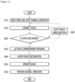
- FIG. 12 is a flowchart sequentially illustrating the operation of the refrigerator according to the mounting of the device.
- the driving part 16 composed of components for cooling such as a compressor of the refrigerator 1 is driven, and the operation of the refrigerator 1 can start.
- the control part 14 controls the operation of the driving part 16 according to the manipulation input from the manipulation part 17.
- the control part 14 controls the operation of the driving part 16 so that the temperature of the storage space detected by the temperature sensor 18 is maintained at a set temperature, and such normal operation can be referred to as a general operation.
- the user can mount the device 100 on the refrigerator 1 as needed.
- the location where the device 100 is mounted can be a set location among a plurality of accommodation members 200, such as the first accommodation member 200 and the second accommodation member 200, and the user can mount the device 100 at a location suitable for the operation of the device 100.
- the user In order to mount the device 100, the user separates the cover 190 from the accommodation member 200 to expose the second connection part 130, and mounts the device 100 in the mounting space 211 where the second connection part 130 is exposed.
- the control part 14 can recognize the device 100.
- the device 100 By simply mounting the device 100 on the accommodation member 200, power is supplied to the device 100, and the device 100 and the control part 14 are connected in a communicable state, so that information of the device 100 can be recognized.
- the control part 14 may store a program for driving the device 100.
- the program for driving the device 100 may be received and installed from a remote location.
- the program for operating the device 100 may be updated in the control part 14 regardless of whether the device 100 is mounted.
- the program for driving may be built into the device 100 and the program for driving may be installed in the control part 14 along with the mounting of the device 100.
- the control part 14 activates a corresponding program for the operation of the device 100.
- the information of the actually mounted device 100 is recognized, and the corresponding program is activated accordingly.
- the normal recognition state of the additional device 100 can be guided.
- the output part 141 or the remote user terminal can be notified of the normal recognition completion of the device 100 and the standby state of the operation of the device 100.
- the device 100 can be operated according to the set corresponding program. Although it may vary according to the type of the device 100, if the corresponding program is normally activated, the device 100 performs the set operation along with recognition of the device 100.
- the user may set and manipulate the operation of the device 100, and when the corresponding program is activated, the user may set the operation of the device 100 through the manipulation of the manipulation part 17 or the user terminal.
- the control part 14 controls the driving part 16 to continuously perform the general operation.
- other operations that are dependent on or changed by the device 100 other than the general operation may be performed.
- the non-recognition state of the additional device 100 is notified.
- control part 14 can inform the user that there is a problem with the mounting or recognition of the device 100 through the output part 141 or the user terminal. At this time, the control part 14 can analyze which part of the mounting or recognition of the device 100 caused the problem and inform the user of the problem, so that the user can take appropriate measures to solve the problem.
- the user may be able to mount a plurality of devices 100, and the plurality of devices 100 may be selectively mounted at appropriate locations in a plurality of accommodation members 200, such as the first accommodation member 201 and the second accommodation member 202.
- the recognition and activation of the device 100 may be performed by sequentially repeating the above-described process, and when the plurality of devices 100 are mounted at the same time, the plurality of devices 100 may be recognized simultaneously.
- the present disclosure may have various other embodiments in addition to the embodiments described above.
- the device may be placed on the door side rather than the cabinet inside the storage space.
- the device may be mounted in a combination of the mounting positions of the above-described embodiment as well as the mounting positions of other embodiments described below.
- FIG. 13 is a partial perspective view illustrating the mounting state of the device according to another embodiment of the present disclosure.
- a refrigerator 1 according to another embodiment of the present disclosure may be provided with a plurality of doors 20 for opening and closing the storage space of the cabinet 10.
- the refrigerating compartment door 21 for opening and closing the refrigerating compartment 12 may include the main door 40 and the sub door 30.
- a viewing part 31 may be formed in the sub-door 30 to allow viewing of the opening 41 of the main door 40.
- the rear surface of the sub-door 30 may be formed by a door liner 33.
- a device 100' may be provided on one side of the door liner 33 corresponding to the inner side of the opening 41.
- the device 100' may be a camera device, and the food stored in the opening 41 or a space communicating with the opening 41 may be photographed and analyzed by the device 100'.
- the door liner 33 may be provided with an accommodation member 200', and the device 100' may be detachably mounted on the accommodation member 200'.
- a plurality of accommodation members 200' may be provided on the door liner 33. Accordingly, the device 100' may be mounted by the user according to the user's needs.
- the accommodation member 200' when the device 100' is mounted on the accommodation member 200', the accommodation member 200' can be shielded by the device cover 110' of the device 100', and the module 140' can be exposed through the device cover 33 to photograph the inside of the opening 41.
- the cover 190' may be mounted on the accommodation member 200' instead of the device 100'.
- the cover 190' shields the accommodation member 200' so that the mounting space 211 is not exposed, and the cover 190' forms a part of the outer appearance of the rear surface of the sub-door 30.
- the device 100' may be mounted on the rear surface of the sub-door 30, and although not illustrated in detail, it may be positioned on the rear surface of the door 20, 40 in the same manner.
- Fig. 14 is a partial perspective view illustrating the mounting state of the device according to another embodiment of the present disclosure.
- the refrigerator may be provided with a plurality of doors for opening and closing the storage space of the cabinet.
- the doors may include a refrigerating compartment door and a freezing compartment door.
- the refrigerating compartment door 21 may be configured as a pair of French type doors arranged side by side. In addition, the pair of refrigerating compartment doors 21 may be rotated to partially or completely open and close the refrigerating compartment 12.
- a filler 203 may be provided at the end part of one of the pair of refrigerating compartment doors 21.
- the filler 203 serves to shield the space between the pair of refrigerating compartment doors 21, and may be extended vertically along the end part of the refrigerating compartment door 21 and may be rotatably mounted.
- the filler 203 may be rotatably mounted on an end part of one side of the refrigerating compartment door 21, that is, an end part adjacent to the other refrigerating compartment door 22.
- the filler 203 may be mounted on a door liner 202 forming the rear surface of the refrigerating compartment door 21. Then, when the refrigerating compartment door 21 is open, the filler maintains a state where the side end of the refrigerating compartment door 21 is bent, and when the refrigerating compartment door 21 is closed, the filler unfolds and blocks the space between the pair of refrigerating compartment doors 21 by rotating.
- a device 100" may be provided on one side of the filler 203.
- the device 100" may be a camera device, and food stored inside the refrigerating compartment 12 may be photographed and analyzed by the device 100".
- the filler 203 may be provided with an accommodation member 200", and the device 100" may be detachably mounted on the accommodation member 200".
- a plurality of accommodation members 200" may be provided on the filler 203. Accordingly, the device 100" may be mounted by the user according to the user's needs.
- the accommodation member 200" when the device 100" is mounted on the accommodation member 200", the accommodation member 200" can be shielded by the device cover 110" of the device 100", and the module 140" can be exposed through the device cover 110" to photograph the inside of the refrigerating compartment 12.
- the cover 190" may be mounted on the accommodation member 200" instead of the device 100".
- the cover 190" shields the accommodation member 200" so that the mounting space 211 is not exposed, and the cover 190" forms a part of the outer appearance of the rear surface of the filler 203.
- the device 100" may be mounted on the filler 203 provided on the refrigerating compartment door 21, and although not illustrated in detail, the filler 203 on which the device 100" is mounted may be provided on the freezing compartment door 22.
- the refrigerator according to an embodiment of the present disclosure has high industrial applicability because it can provide a product that suits the user's taste by mounting additional devices inside the refrigerator.
Landscapes
- Engineering & Computer Science (AREA)
- Chemical & Material Sciences (AREA)
- Combustion & Propulsion (AREA)
- Physics & Mathematics (AREA)
- Mechanical Engineering (AREA)
- Thermal Sciences (AREA)
- General Engineering & Computer Science (AREA)
- Devices That Are Associated With Refrigeration Equipment (AREA)
- Cold Air Circulating Systems And Constructional Details In Refrigerators (AREA)
Abstract
Description
- The present disclosure relates to a refrigerator.
- In general, a refrigerator is a home appliance that allows food to be stored at low temperatures in an internal storage space that is shielded by a door. To this end, the refrigerator is configured to cool the inside of the storage space by using cold air generated through heat exchange with a refrigerant that circulates a refrigeration cycle, thereby allowing the stored food to be stored in an optimal condition.
- Recently, refrigerators are becoming larger and more multifunctional in line with the changing eating habits and the trend toward more sophisticated products, and refrigerators equipped with various structures and convenient devices for the convenience of users and efficient use of internal space are being released.
- For example, a deodorizing device for removing odors inside the refrigerator may be mounted inside the refrigerator. In addition, a camera may be mounted inside the refrigerator to check the food inside the refrigerator. In addition, various sensors may be provided to check the storage state of food stored inside the refrigerator.
-
Korean Patent Publication No. 10-2016-0089725 - However, in refrigerators with this type of structure, there is a problem in that the camera is fixedly mounted on the refrigerator, so the camera cannot be placed in a desired location. In addition, there is a problem in that the camera is placed even when it is not necessary, which increases the product price, and there is a problem in that a diverse product lineup cannot be composed.
- An object of an embodiment of the present disclosure is to provide a refrigerator in which a user can additionally mount a desired device.
- An object of an embodiment of the present disclosure is to provide a refrigerator in which a user can additionally mount devices at various locations within the refrigerator.
- An object of an embodiment of the present disclosure is to provide a refrigerator whose performance can be upgraded through selective mounting of a device in a user's refrigerator.
- A refrigerator according to an embodiment of the present disclosure includes a cabinet forming a storage space; a door opening and closing the storage space; an accommodation member provided in the storage space; and a device detachably mounted on the accommodation member and performing an additional function in a connected state, in which the accommodation member may be provided with a first connection part connected to a control part for controlling the device, the device may be provided with a second connection part, and when the device is mounted, the first connection part and the second connection part may be connected to each other so as to supply power to the device and transmit signals to the control part.
- The cabinet may include an outer case forming an outer appearance; an inner case forming the storage space; and an insulation material filled between the outer case and the inner case, and in which the accommodation member may be provided in the inner case and is embedded by the insulation material.
- The accommodation member may form a recessed space to accommodate at least a part of the device, and the space may be recessed into the wall surface of the storage space.
- An insulation member which is in contact with the insulation member and has a higher insulation coefficient than the insulation member MAY BE disposed on the outer surface of the accommodation member.
- The first connection part may be provided in the space and protrudes toward the direction into which the device is inserted.
- The accommodation member may include a case forming a space in which the device is received, and the first connection part may be provided at a position facing the second connection part and may be connected to the second connection part during the mounting process of the device.
- A fitting part may be formed which is formed in a shape corresponding to each other around the case and the device, and when the device is mounted, comes into contact with each other to have a directionality.
- The refrigerator may further include a guide projection protruding from the device and extending in the same direction as the second connection part; and a guide part recessed into the case facing the guide projection and formed on the same surface as the first connection part, in which while the guide projection is inserted into the guide part, the coupling the first connection part and the second connection part may be guided.
- The guide protrusion may be formed symmetrically with respect to the second connection part.
- The guide projection may be formed to protrude further than the second connection part.
- The device may include a module connected to the second connection part and for driving the device, a main body accommodating the module and through which the second connection part is exposed; and a device cover shielding the space and is exposed to the storage space.
- The refrigerator may further include a cover detachably mounted on the accommodation member and shielding the first connection part when the device is not mounted.
- The cover may form a part of the wall surface of the storage space while being mounted on the accommodation member.
- A plurality of the accommodation members may be provided in the storage space, and the device may be mounted in at least one of the plurality of accommodation members.
- The first connection part and the second connection part may be configured as USB terminals.
- The control part may be configured to recognize the type of the device, and a corresponding program for driving the recognized device may be stored.
- The device may be exposed to the inside of the storage space while mounted on the accommodation member.
- The accommodation member may be provided in a door liner forming the rear surface of the door.
- The refrigerator may further include a filler shielding between a pair of doors disposed in parallel, in which the accommodation member may be provided in the filler.
- The following effects can be expected from a refrigerator according to an embodiment of the proposed disclosure.
- In a refrigerator according to an embodiment of the present disclosure, a device having a desired function can be selectively additionally mounted inside the storage space according to the user's needs. Accordingly, there is an advantage in that a product that meets the user's preference can be provided by allowing the user to add a desired function to a refrigerator having basic functions after it is sold.
- In addition, additional functions or upgraded functions can be provided through the device even after the sale of the refrigerator, and users have the advantage of being able to improve the performance of the product by mounting the device without replacing the entire refrigerator system.
- In addition, by disposing a plurality of accommodation members so that they can be mounted in various locations according to the type or number of the devices, there is an advantage in that various devices can be selectively mounted in desired locations according to the user's needs.
- In addition, when mounting of the device is not required, the outer appearance of the storage space can be prevented from being disturbed by shielding the accommodation member through the cover, and there is also an advantage in that the connection part of the accommodation member can be prevented from being contaminated or causing safety problems.
- In addition, the device can be connected to the accommodation member by the first connection part and the second connection part so that power and signal transmission can be enabled, thereby facilitating installation of the device. In particular, the first connection part and the second connection part can have a standardized terminal structure so that various types of the device can have the same connecting structure, thereby allowing the device to have the same connecting structure regardless of the type of the device.
- In addition, the device and the accommodation member are formed with a guide projection and a guide part so that the first connection part and the second connection part can be connected without a separate operation during the process of mounting the device on the accommodation member, thereby making mounting of the device easier. In addition, there is an advantage in that incorrect assembly of the device is prevented and mounting of the device is possible with accurate placement by the guide projection and the guide part.
-
-
FIG. 1 is a perspective view illustrating a refrigerator of an embodiment of the present disclosure. -
FIG. 2 is a partial perspective view illustrating a state where a door of the refrigerator is open. -
FIG. 3 is a view illustrating a state where the device is not mounted inFIG. 2 . -
FIG. 4 is a cross-sectional view illustrating a state where a device is mounted according to an embodiment of the present disclosure. -
FIG. 5 is a schematic view illustrating the coupled structure of an accommodation member and a device that are coupled to each other. -
FIG. 6 is a cross-sectional view illustrating a state where the device is separated. -
FIG. 7 is a cross-sectional view taken along line VII-VII' ofFIG. 2 . -
FIG. 8 is an exploded perspective view illustrating the device. -
FIG. 9 is a cross-sectional view taken along line IX-IX' ofFIG. 3 . -
FIG. 10 is a perspective view illustrating a cover of an embodiment of the present disclosure. -
FIG. 11 is a block diagram schematically illustrating the connection state of the main components of the refrigerator. -
FIG. 12 is a flowchart sequentially illustrating the operation of the refrigerator according to the mounting of the device. -
FIG. 13 is a partial perspective view illustrating the mounting state of the device according to another embodiment of the present disclosure. -
Fig. 14 is a partial perspective view illustrating the mounting state of the device according to another embodiment of the present disclosure. - Hereinafter, specific embodiments of the present disclosure will be described in detail with reference to the drawings. However, the present disclosure is not limited to the embodiments in which the idea of the present disclosure is presented, and other regressive disclosures or other embodiments included within the scope of the idea of the present disclosure can be easily proposed by adding, changing, deleting, or the like other components.
- Before the explanation, the direction is defined. In the embodiment of the present disclosure, the direction in which the front surface of the door illustrated in
FIG. 1 is facing may be defined to as a front direction, the direction toward the cabinet may be defined to as a rear direction based on the front surface of the door, the direction facing the floor where the refrigerator is installed may be defined to as a lower direction, and the direction away from the floor may be defined to as a upper direction. -
FIG. 1 is a perspective view illustrating a refrigerator according to an embodiment of the present disclosure. - As illustrated in the drawing, a
refrigerator 1 according to an embodiment of the present disclosure may have an outer appearance formed by acabinet 10 forming a storage space and a door 20 for opening and closing the storage space. - The storage space inside the
cabinet 10 can be partitioned vertically bypartition walls 11, and arefrigerating compartment 12 can be formed in the upper part of thecabinet 10 and a freezingcompartment 13 can be formed in the lower part of thecabinet 10. - In addition, a
control part 14 for controlling the overall operation of therefrigerator 1 may be formed on the upper surface of thecabinet 10. Thecontrol part 14 may control the operation of therefrigerator 1 as well as the operation of thedevice 100 to be described below. In addition, anoutput part 141 is connected to thecontrol part 14 to output the operation state of the refrigerator. Theoutput part 141 may include a display that displays information on a screen or a speaker that displays information in voice. In addition, anmanipulation part 17 is connected to thecontrol part 14 to input a manipulation for the operation of therefrigerator 1. In addition to a physical input method such as a button, a switch, or a touch, themanipulation part 17 may include a microphone capable of inputting voice. - In the embodiment of the present disclosure, the
control part 14 is described as being placed on the upper surface of thecabinet 10, but thecontrol part 14 may be provided at various locations in therefrigerator 1, and a plurality of control part may be provided and placed at different locations, respectively. - The door 20 may be composed of a
refrigerating compartment door 21 and a freezingcompartment door 22. The refrigeratingcompartment door 21 may be configured to open and close the open front surface of therefrigerating compartment 12 by rotating, and the freezingcompartment door 22 may be configured to open and close the open front surface of the freezingcompartment 13 by rotating. Meanwhile, the refrigeratingcompartment door 21 may be called an upper door because it is provided at the top, and the freezingcompartment door 22 may be called a lower door because it is provided at the bottom. - In addition, a pair of the
refrigerating compartment doors 21 may be provided in the left and right direction so that therefrigerating compartment 12 may be shielded by the pair ofdoors 21. In addition, a pair of freezingcompartment doors 22 may be provided in the left and right direction so that the freezingcompartment 13 may be opened and closed by the pair of doors. Of course, the freezingcompartment door 22 may be configured to be capable of pulling out in a drawer-like manner as needed, and may be configured with one or more doors. - In the embodiment of the present disclosure, a refrigerator is described as an example in which a bottom freeze type refrigerator with a freezing
compartment 13 provided at the bottom is applied with a French type door in which a pair of doors rotate to open and close each space, but the present disclosure can be applied to all types of refrigerators in which a camera module can be installed regardless of the shape of the refrigerator. - Meanwhile, at least one
door 21 of the pair of refrigeratingcompartment doors 21 may be composed of amain door 40 and asub door 30. Themain door 40 is rotatably mounted on thecabinet 10 and may open and close therefrigerating compartment 12. In addition, an opening 41 (inFIG. 2 ) may be formed through themain door 40. - The sub-door 30 is provided in front of the
main door 40 and can be rotatably mounted on themain door 40. In addition, the sub-door 30 can open and close theopening 41. In addition, aviewing part 31 that can view the inside of theopening 41 can be formed on the sub-door 30. Theviewing part 31 can be composed of at least one transparent panel and can be selectively configured so that the inside of theopening 41 is visible. In addition, if necessary, theviewing part 31 can be composed of a display device such as an LCD capable of screen output or a transparent LCD. - Below, the structure inside the storage space of the
refrigerator 1 will be examined with reference to the drawings. -
FIG. 2 is a partial perspective view illustrating a state where a door of the refrigerator is open, andFIG. 3 is a view illustrating a state where the device is not mounted inFIG. 2 . - As illustrated in the drawing, the
cabinet 10 may include aninner case 102 forming an inner surface of the storage space, and an outer case 101 i that is coupled with theinner case 102 and forming an outer appearance of thecabinet 10. In addition, aninsulation material 103 formed by injecting a foaming agent may be filled between theinner case 102 and theouter case 101. - In the
outer case 101 is formed of a metal material to form the outer shape of thecabinet 10, and in theinner case 102 is formed by vacuum forming with a relatively thin plastic material to form the inner shape of the storage space. - In the
inner case 102 may form the upper and lower surfaces, left and right sides of therefrigerating compartment 12. In addition, if necessary, ininner case 102 may form at least a part of the rear surface of therefrigerating compartment 12. In addition, the rear surface of therefrigerating compartment 12 may be formed by thegrill fan assembly 121. Thegrill fan assembly 121 may form a flow path for the flow of cold air inside the refrigerator. - Meanwhile, a
device 100 may be mounted to theinner case 102. Thedevice 100 may be selectively mounted on therefrigerator 1 to upgrade the function of therefrigerator 1 or provide an additional function. In addition, thedevice 100 may have an independent function added to the general cooling operation of therefrigerator 1. Thedevice 100 may be referred to as a module device, a device module, a module device, an accessory, an additional device, or the like. - In order to mount the
device 100, anaccommodation member 200 is formed on theinner case 102, and theaccommodation member 200 can be configured to allow a user to selectively mount thedevice 100. At this time, theaccommodation member 200 is configured to enable power supply and signal processing when thedevice 100 is mounted, and can be configured to automatically recognize and operate when thedevice 100 is mounted. - Meanwhile, at least one of the
accommodation members 200 may be provided inside the refrigeratingcompartment 12. Accordingly, the user may mount thedevice 100 in an appropriate location according to the type and function of thedevice 100. - For example, the
accommodation member 200 may be provided on at least one of the upper surface and the left and right sides of theinner case 102. In addition to theinner case 102, theaccommodation member 200 may also be placed in the component in the refrigerator such as thegrill fan assembly 121. In addition, when thedevice 100 is not mounted on theaccommodation member 200, acover 190 may be mounted to shield the space formed by theaccommodation member 200. - Meanwhile, looking at an example in which the
device 100 is mounted with reference toFIG. 2 , thedevice 100 may be provided at the center of the upper surface of theinner case 102. For example, thedevice 100 may be a camera device. Accordingly, thedevice 100 may photograph the inside of the storage space, i.e., the refrigeratingcompartment 12. - In addition to the camera device, the
device 100 may use various devices such as a thermal imaging camera, an ion deodorizer, a carbon dioxide detector, a gas sensor, a reader for recognizing barcodes or QR codes, an additional cooling device composed of a thermoelectric element, a Wi-Fi dongle, or the like. - The
device 100 may not be provided when purchasing arefrigerator 1, and may be additionally purchased by the user as needed, or may be additionally provided to upgrade the performance of therefrigerator 1. - The
device 100 can be electrically connected to thecontroller 14, and thus the photographed image can be transmitted to thecontroller 14 and output on the display device or a remote device such as a mobile phone or PC. In addition, the image information acquired from thedevice 100 can be utilized as information for the operation of therefrigerator 1 through processing, or can be transmitted to the user. - In addition, the
accommodation member 200 may be formed to have a sufficient size to enable mounting of various devices (100). In addition, as illustrated inFIG. 3 , when thedevice 100 is not used, a cover may be mounted on theaccommodation member 200 to shield theaccommodation member 200. Thecover 190 may be formed to have the same color or texture as theinner case 102, and may have a sense of unity with theinner case 102 when mounted on theaccommodation member 200. In addition, thecover 190 may be formed so that the outer surface of thecover 190 is positioned on the same plane as theinner case 102 when mounted on theaccommodation member 200. - In this way, the user can mount the
device 100 in a suitable location among a plurality ofaccommodation members 200, and acover 190 is mounted on anaccommodation member 200 in which thedevice 100 is not mounted so that the interior of theaccommodation member 200 is not exposed. - Below, the structure of the accommodation member and device will be examined in more detail with reference to the drawings.
-
FIG. 4 is a cross-sectional view illustrating a state where a device is mounted according to an embodiment of the present disclosure,FIG. 5 is a schematic view illustrating the coupled structure of an accommodation member and a device that are coupled to each other, andFIG. 6 is a cross-sectional view illustrating a state where the device is separated. - As illustrated, the
accommodation member 200 can be mounted on the additionalfunction performing part 102 in an inner connection state. Theaccommodation member 200 can be mounted so as to be exposed through an opening formed in the additionalfunction performing part 102 in an inner connection state, and a portion of theaccommodation member 200 can be embedded in theinsulation material 103 so that the mounting position can be firmly fixed. - The
accommodation member 200 may include ancase 210 that forms a recessed mountingspace 211 in which thedevice 100 can be mounted. In addition, thecase 210 may be opened toward therefrigerating compartment 12. Abent edge 214 may be formed around the circumference of the opened surface of thecase 210. In addition, theedge 214 may be coupled with theinner case 102 to fix theaccommodation member 200 and prevent leakage of theinsulation material 103. - The mounting
space 211 can form a space in which themain body 120 of thedevice 100 is accommodated. In addition, the mountingspace 211 can be formed in a shape corresponding to themain body 120. - For example, as illustrated in (a) of
Fig. 5 , an additional function performingfitting part 213 in a connected state may be formed around the inner side of thecase 210 in the connected state. The casefitting part 213 may be formed in a shape in which a part of the mountingspace 211 is cut out. - In addition, as illustrated in (b) of
Fig. 5 , a main body-fittingpart 123 may be formed around the outer surface of themain body 120. The main body-fittingpart 123 may be formed at a position corresponding to the casefitting part 213. - Therefore, when the
device 100 is mounted on theaccommodation member 200, themain body 120 is inserted into the inside of thecase 210, and at this time, the casefitting part 213 and the mainbody fitting part 123 can be mounted in a form in which they come into contact with each other. In other words, thedevice 100 can be mounted on theaccommodation member 200 with directionality, and therefore, thedevice 100 can be mounted in an accurate disposition without being incorrectly mounted. In addition, thefirst connection part 220 of theaccommodation member 200 and thesecond connection part 130 of thedevice 100 can be accurately connected by this mounting structure. - A mounting
part 214 having thefirst connection part 220 may be formed on the inner surface of thecase 210. The mountingpart 214 may be further recessed into the mountingspace 211, and thefirst connection part 220 may be mounted therein. - The mounting
part 214 may extend in a direction opposite to the opening of thecase 210, and may be configured such that the end thereof is bent to support the end part of thefirst connection part 220. Accordingly, even if thefirst connection part 220 is pressed when thedevice 100 is mounted, thefirst connection part 220 may be prevented from being separated. In addition, the mountingpart 214 may communicate with the mountingspace 211, and therefore, when an abnormality occurs in thefirst connection part 220, thefirst connection part 220 may be separated from the mounting part. - Meanwhile, the
first connection part 220 may include afirst body 222 that is fixed to the mountingpart 214 and afirst terminal 221 provided on thefirst body 222. - The
first body 222 may be formed in a shape corresponding to the mountingpart 214 so that it can be inserted and fixed inside the mountingpart 214. In addition, abody coupling part 223 may be formed at an end part of thefirst body 222 to be coupled with the opened circumference of the mountingpart 214. In addition, thefirst body 222 may be formed in a recessed shape so that thesecond connection part 130 may be inserted. - The
first terminal 221 is formed in the recessed center of thefirst body 222 and can protrude in the insertion direction of thesecond connection part 130. In addition, it can be electrically connected to thesecond terminal 131 of thesecond connection part 130 by coming into contact with each other. Thefirst terminal 221 and thesecond terminal 131 can be formed in a male-female structure and connected to each other. For example, thefirst terminal 221 and thesecond terminal 131 can be formed like a standardized USB terminal structure. In addition, thefirst terminal 221 and thesecond terminal 131 can have another standardized terminal structure that can be electrically connected to each other. - A
guide part 212 that guides the mounting of thedevice 100 may be formed on theaccommodation member 200. Theguide part 212 may be formed on one side of thecase 210 that is the same as the surface on which the mountingpart 214 is formed. In other words, theguide part 212 may be formed on thecase 210, and theguide part 212 may be formed on both sides based on the mountingpart 214. - The
guide part 212 may be formed in a groove shape into which aguide projection 122 protruding from thedevice 100 is inserted. Theguide part 212 may be formed in a size and shape corresponding to theguide projection 122. Accordingly, when thedevice 100 is mounted on theaccommodation member 200, theguide projection 122 may be inserted into theguide part 212. In addition, when theguide projection 122 is inserted into theguide part 212, the mounting position of thedevice 100 may be guided, and thefirst connection part 220 and thesecond connection part 130 may be naturally coupled. In other words, when thedevice 100 is mounted so that theguide protrusion 122 is inserted into theguide part 212, thefirst connection part 220 and thesecond connection part 130 are connected to each other, so that thedevice 100 can be in an operable state. At this time, theguide protrusion 122 and theguide part 212 may be interlocked or pressed into each other, and thedevice 100 may be maintained in a state where it is mounted on theaccommodation member 200. - The
device 100 may include amain body 120 accommodated in the mountingspace 211 and adevice cover 110 that shields the mountingspace 211. - The
main body 120 may be formed in a shape corresponding to the mountingspace 211 of theaccommodation member 200. In addition, a mainbody fitting part 123 may be formed on one side of the circumference of themain body 120. The mainbody fitting part 123 may be formed in a shape corresponding to a position facing the casefitting part 213. Therefore, in the process of inserting themain body 120 into the mountingspace 211, thedevice 100 may be mounted while the mounting position is aligned. - An
accommodation space 121 may be formed inside themain body 120 to accommodate amodule 140 for the operation of thedevice 100. For example, if thedevice 100 is a camera device, themodule 140 may be a camera module. Themodule 140 may include a substrate and may be placed inside themain body 120. In addition, themodule 140 may be electrically connected to the second connection part. - The
second connection part 130 may protrude from themain body 120 and may be formed at a position facing thefirst connection part 220. Thesecond connection part 130 may include asecond terminal 131. Thesecond terminal 131 may be formed to accommodate thefirst terminal 221, and when thefirst connection part 220 and thesecond connection part 130 are coupled, thefirst terminal 221 and thesecond terminal 131 may be in contact with each other and electrically connected. In other words, power for the operation of thedevice 100 may be supplied through the connection between thefirst terminal 221 and thesecond terminal 131. In addition, thedevice 100 and thecontrol part 14 can be connected to enable transmission of a signal through the connection between thefirst terminal 221 and thesecond terminal 131. Accordingly, thedevice 100 can perform a set operation and transmit information generated by the operation to thecontrol part 14. - A
guide protrusion 122 may be formed on themain body 120. Theguide protrusion 122 may be formed on the same surface as thesecond connection part 130. In addition, theguide protrusion 122 may protrude from a surface facing theguide part 212. - A plurality of
guide protrusions 122 may protrude from both sides of thesecond connection part 130. Theguide protrusion 122 may protrude in the same protrusion direction as thesecond connection part 130. In addition, the protrusion height H2 of theguide protrusion 122 may be formed higher than the protrusion height H1 of thesecond connection part 130. In other words, the protruding end part of theguide protrusion 122 may protrude further than the protruding end part of thesecond connection part 130. Accordingly, even if thedevice 100 is dropped or collides with other components, it may be protected by theguide protrusion 122, and contact with thesecond connection part 130 may be prevented, thereby preventing thesecond connection part 130 from being damaged. - In addition, when the end part of the
guide protrusion 122 is completely inserted into theguide part 212 and comes into contact with the bottom of theguide part 212, thefirst connection part 220 and thesecond connection part 130 can be completely coupled to each other. Therefore, the connection state of thefirst connection part 220 and thesecond connection part 130 can be confirmed and guaranteed by the coupling of theguide protrusion 122 and theguide part 212. - The
device 100 may further include adevice cover 110. Thedevice cover 110 may form one surface of themain body 120 and may shield the opening of theaccommodation member 200. Thedevice cover 110 may extend outward along the circumference of themain body 120 and may shield the opening of the mountingspace 211. Accordingly, when thedevice 100 is mounted on theaccommodation member 200, thedevice cover 110 may be exposed to the storage space to form an exposed appearance of thedevice 100. - In addition, according to the type of the
device 100, at least a part of themodule 140 may be exposed by passing through thedevice cover 110. For example, if thedevice 100 is a camera device, a part of the camera device may be exposed by passing through thedevice cover 110 to photograph food inside the storage space. - Below, the
device 100 will be examined in more detail with reference to the drawings in terms of its mounted and unmounted state. -
FIG. 7 is a cross-sectional view taken along line VII-VII' ofFIG. 2 , andFIG. 8 is an exploded perspective view illustrating the device. - As illustrated, the
accommodation member 200 is mounted on theinner case 102, and the mountingspace 211 inside theaccommodation member 200 can provide a space that is more recessed than the outer surface of theinner case 102. - Meanwhile, due to the installation of the
accommodation member 200, the space between theinner case 102 and theouter case 101 is reduced, and aninsulation member 104 can be further disposed in theaccommodation member 200. Unlike theinsulation material 103, theinsulation member 104 can be mounted in a molded state, and can be formed in a plate or sheet shape covering theaccommodation member 200. Theinsulation member 104 can be formed of a material having better insulation performance than theinsulation material 103. In other words, theinsulation member 104 can be formed of a material having a higher insulation coefficient than theinsulation material 103. For example, theinsulation member 104 can be formed of a vacuum insulation material. By disposing theinsulation member 104 on the outer surface of theaccommodation member 200, it is possible to prevent the insulation performance from being reduced at the location where theaccommodation member 200 is mounted. - In addition, the
device 100 may include themain body 120 and thedevice cover 110. Themain body 120 may be formed to have an open bottom, and may be formed to accommodate themodule 140 inside. In addition, anopening 123 may be formed on the upper surface of themain body 120 through which thefirst connection part 220 protrudes. In addition, theguide protrusions 122 may be formed on both sides of theopening 123. - The
device cover 110 may include aplate part 111 that shields the opened lower surface of themain body 120 and aedge part 112 surrounding the plate part. Accordingly, thedevice cover 110 may be formed in a shape in which the upper surface is open. In addition, the lower end of the covermain body 120 may be mounted so as to be in contact with theedge part 112. - Meanwhile, the
module 140 may be fixedly mounted on the inside of thedevice cover 110. Themodule 140 may be mounted on thedevice cover 110 by a screw 115. Therefore, in order to service the module, thedevice cover 110 may be separated to access themodule 140. In addition, aboss device cover 110. A plurality ofbosses 113 may be formed. The screw 115 passing through theboss 113 may be fastened to the inside of themain body 120. Therefore, thedevice cover 110 and themain body 120 may be maintained in a state of being firmly coupled by the screw 115. In addition, although not illustrated in detail, the space between thedevice cover 110 and themain body 120 may be sealed to prevent water or moisture from penetrating. -
FIG. 9 is a cross-sectional view taken along line IX-IX' ofFIG. 3 , andFIG. 10 is a perspective view illustrating a cover according to an embodiment of the present disclosure. - As illustrated, when the
device 100 is not mounted, thecover 190 can be mounted on theaccommodation member 200 to shield the mounting space of theaccommodation member 200. In addition, the exposure of the recessed space of theaccommodation member 200 can be prevented, and a part of the inner surface of the storage space can be formed by thecover 190. - In addition, by mounting the
cover 190, exposure of thesecond connection part 130 inside the mountingspace 211 can be prevented, and thus damage to thesecond connection part 130 and safety accidents can be prevented. - The
cover 190 may include acover plate 191 of the plate shape and acover edge 192 bent along the circumference of thecover plate 191. When thecover 190 is mounted on theaccommodation member 200, thecover plate 191 may shield the mountingspace 211, and thecover edge 192 may come into contact with the inner circumference of the mountingspace 211. - Meanwhile, a plurality of
cover fixing parts 193 may be formed on the inner side of thecover 190. Thecover fixing parts 193 may extend upward from thecover plate 191 or thecover edge 192, and may be formed to be caught and restrained on the inner side of thecase 210 when thecover 190 is mounted. - The
cover fixing part 193 may be formed at opposite positions on both sides so that both sides of thecover 190 may be coupled to theaccommodation member 200. In addition, thecover fixing part 193 may be formed to have elasticity, so that when thecover 190 is mounted or separated, thecover fixing part 193 may be elastically deformed and coupled to thecase 210. - Meanwhile, the
insulation member 104 is disposed on the outer surface of theaccommodation member 200 so that the insulation performance can be maintained even when the mountingspace 211 of theaccommodation member 200 is empty. - Below, the operation of the
refrigerator 1 will be described in detail with reference to the drawings. -
FIG. 11 is a block diagram schematically illustrating the connection state of the main components of the refrigerator, andFIG. 12 is a flowchart sequentially illustrating the operation of the refrigerator according to the mounting of the device. - As illustrated in the drawing, when power is input to the
refrigerator 1, the drivingpart 16 composed of components for cooling such as a compressor of therefrigerator 1 is driven, and the operation of therefrigerator 1 can start. At this time, thecontrol part 14 controls the operation of the drivingpart 16 according to the manipulation input from themanipulation part 17. Then, thecontrol part 14 controls the operation of the drivingpart 16 so that the temperature of the storage space detected by thetemperature sensor 18 is maintained at a set temperature, and such normal operation can be referred to as a general operation. [S100] - When general operation is started, the user can mount the
device 100 on therefrigerator 1 as needed. At this time, the location where thedevice 100 is mounted can be a set location among a plurality ofaccommodation members 200, such as thefirst accommodation member 200 and thesecond accommodation member 200, and the user can mount thedevice 100 at a location suitable for the operation of thedevice 100. - In order to mount the
device 100, the user separates thecover 190 from theaccommodation member 200 to expose thesecond connection part 130, and mounts thedevice 100 in the mountingspace 211 where thesecond connection part 130 is exposed. [S210] - When the
device 100 is mounted and thefirst connection part 220 and thesecond connection part 130 are connected to each other, thecontrol part 14 can recognize thedevice 100. - By simply mounting the
device 100 on theaccommodation member 200, power is supplied to thedevice 100, and thedevice 100 and thecontrol part 14 are connected in a communicable state, so that information of thedevice 100 can be recognized. - At this time, the
control part 14 may store a program for driving thedevice 100. In addition, if therefrigerator 1 is equipped with acommunication part 19 and has a structure capable of communicating with the outside, the program for driving thedevice 100 may be received and installed from a remote location. In addition, when thedevice 100 is released through periodic communication with a remote location, the program for operating thedevice 100 may be updated in thecontrol part 14 regardless of whether thedevice 100 is mounted. Of course, the program for driving may be built into thedevice 100 and the program for driving may be installed in thecontrol part 14 along with the mounting of thedevice 100. [S220] - When the mounting and recognition of the
device 100 is completed, thecontrol part 14 activates a corresponding program for the operation of thedevice 100. In other words, among the programs ofvarious devices 100 installed in thecontrol part 14, the information of the actually mounteddevice 100 is recognized, and the corresponding program is activated accordingly. [S230] - After the mounting and recognition of the
device 100 is completed and the corresponding program for driving thedevice 100 is activated, the normal recognition state of theadditional device 100 can be guided. - For example, the
output part 141 or the remote user terminal can be notified of the normal recognition completion of thedevice 100 and the standby state of the operation of thedevice 100. [S240] - Meanwhile, when normal mounting and recognition of the
device 100 are completed, thedevice 100 can be operated according to the set corresponding program. Although it may vary according to the type of thedevice 100, if the corresponding program is normally activated, thedevice 100 performs the set operation along with recognition of thedevice 100. - Of course, the user may set and manipulate the operation of the
device 100, and when the corresponding program is activated, the user may set the operation of thedevice 100 through the manipulation of themanipulation part 17 or the user terminal. [S250] - While the operation of the
device 100 is performed by the response program, thecontrol part 14 controls the drivingpart 16 to continuously perform the general operation. Of course, according to the type and operation of thedevice 100, other operations that are dependent on or changed by thedevice 100 other than the general operation may be performed. [S120] - Meanwhile, in the process of mounting the
device 100, if thedevice 100 is not mounted normally in theaccommodation member 200 or thedevice 100 is not recognized normally due to another problem, the non-recognition state of theadditional device 100 is notified. - In other words, the
control part 14 can inform the user that there is a problem with the mounting or recognition of thedevice 100 through theoutput part 141 or the user terminal. At this time, thecontrol part 14 can analyze which part of the mounting or recognition of thedevice 100 caused the problem and inform the user of the problem, so that the user can take appropriate measures to solve the problem. - In addition, the user may be able to mount a plurality of
devices 100, and the plurality ofdevices 100 may be selectively mounted at appropriate locations in a plurality ofaccommodation members 200, such as thefirst accommodation member 201 and thesecond accommodation member 202. - In addition, the recognition and activation of the
device 100 may be performed by sequentially repeating the above-described process, and when the plurality ofdevices 100 are mounted at the same time, the plurality ofdevices 100 may be recognized simultaneously. - The present disclosure may have various other embodiments in addition to the embodiments described above.
- Unlike the above-described embodiment according to another embodiment of the present disclosure, the device may be placed on the door side rather than the cabinet inside the storage space. Of course, the device may be mounted in a combination of the mounting positions of the above-described embodiment as well as the mounting positions of other embodiments described below.
- Hereinafter, the device according to another embodiment of the present disclosure will be described with reference to the drawings. The basic structure of the device and the accommodation member is the same, and since there is only a difference in the disposition positions of the device and the accommodation member, detailed descriptions and drawings of the same components will be omitted and the same drawing symbols will be used for description.
-
FIG. 13 is a partial perspective view illustrating the mounting state of the device according to another embodiment of the present disclosure. - A
refrigerator 1 according to another embodiment of the present disclosure may be provided with a plurality of doors 20 for opening and closing the storage space of thecabinet 10. In addition, the refrigeratingcompartment door 21 for opening and closing therefrigerating compartment 12 may include themain door 40 and thesub door 30. - In addition, a
viewing part 31 may be formed in the sub-door 30 to allow viewing of theopening 41 of themain door 40. - Meanwhile, the rear surface of the sub-door 30 may be formed by a
door liner 33. In addition, a device 100' may be provided on one side of thedoor liner 33 corresponding to the inner side of theopening 41. For example, the device 100' may be a camera device, and the food stored in theopening 41 or a space communicating with theopening 41 may be photographed and analyzed by the device 100'. - The
door liner 33 may be provided with an accommodation member 200', and the device 100' may be detachably mounted on the accommodation member 200'. In addition, a plurality of accommodation members 200' may be provided on thedoor liner 33. Accordingly, the device 100' may be mounted by the user according to the user's needs. - In detail, as illustrated in (a) of
FIG. 13 , when the device 100' is mounted on the accommodation member 200', the accommodation member 200' can be shielded by the device cover 110' of the device 100', and the module 140' can be exposed through thedevice cover 33 to photograph the inside of theopening 41. - Meanwhile, as illustrated in (b) of
Fig. 13 , when the use of the device 100' is not required, the cover 190' may be mounted on the accommodation member 200' instead of the device 100'. The cover 190' shields the accommodation member 200' so that the mountingspace 211 is not exposed, and the cover 190' forms a part of the outer appearance of the rear surface of the sub-door 30. - In this way, the device 100' may be mounted on the rear surface of the sub-door 30, and although not illustrated in detail, it may be positioned on the rear surface of the
door 20, 40 in the same manner. -
Fig. 14 is a partial perspective view illustrating the mounting state of the device according to another embodiment of the present disclosure. - According to another embodiment of the present disclosure, the refrigerator may be provided with a plurality of doors for opening and closing the storage space of the cabinet. In addition, the doors may include a refrigerating compartment door and a freezing compartment door.
- The refrigerating
compartment door 21 may be configured as a pair of French type doors arranged side by side. In addition, the pair of refrigeratingcompartment doors 21 may be rotated to partially or completely open and close therefrigerating compartment 12. - In addition, a
filler 203 may be provided at the end part of one of the pair of refrigeratingcompartment doors 21. Thefiller 203 serves to shield the space between the pair of refrigeratingcompartment doors 21, and may be extended vertically along the end part of the refrigeratingcompartment door 21 and may be rotatably mounted. - The
filler 203 may be rotatably mounted on an end part of one side of the refrigeratingcompartment door 21, that is, an end part adjacent to the otherrefrigerating compartment door 22. Thefiller 203 may be mounted on adoor liner 202 forming the rear surface of the refrigeratingcompartment door 21. Then, when the refrigeratingcompartment door 21 is open, the filler maintains a state where the side end of the refrigeratingcompartment door 21 is bent, and when the refrigeratingcompartment door 21 is closed, the filler unfolds and blocks the space between the pair of refrigeratingcompartment doors 21 by rotating. - Meanwhile, a
device 100" may be provided on one side of thefiller 203. For example, thedevice 100" may be a camera device, and food stored inside the refrigeratingcompartment 12 may be photographed and analyzed by thedevice 100". - The
filler 203 may be provided with anaccommodation member 200", and thedevice 100" may be detachably mounted on theaccommodation member 200". In addition, a plurality ofaccommodation members 200" may be provided on thefiller 203. Accordingly, thedevice 100" may be mounted by the user according to the user's needs. - In detail, as illustrated in (a) of
FIG. 14 , when thedevice 100" is mounted on theaccommodation member 200", theaccommodation member 200" can be shielded by thedevice cover 110" of thedevice 100", and themodule 140" can be exposed through thedevice cover 110" to photograph the inside of therefrigerating compartment 12. - Meanwhile, as illustrated in (b) of
Fig. 14 , when the use of thedevice 100" is not required, thecover 190" may be mounted on theaccommodation member 200" instead of thedevice 100". Thecover 190" shields theaccommodation member 200" so that the mountingspace 211 is not exposed, and thecover 190" forms a part of the outer appearance of the rear surface of thefiller 203. - In this way, the
device 100" may be mounted on thefiller 203 provided on therefrigerating compartment door 21, and although not illustrated in detail, thefiller 203 on which thedevice 100" is mounted may be provided on the freezingcompartment door 22. - The refrigerator according to an embodiment of the present disclosure has high industrial applicability because it can provide a product that suits the user's taste by mounting additional devices inside the refrigerator.
Claims (20)
- A refrigerator comprising:a cabinet (10) forming a storage space;a door opening and closing the storage space;an accommodation member provided in the storage space; anda device detachably mounted on the accommodation member and performing an additional function in a connected state,wherein the accommodation member is provided with a first connection part connected to a control part for controlling the device,wherein the device is provided with a second connection part, andwherein when the device is mounted, the first connection part and the second connection part are connected to each other so as to supply power to the device and transmit signals to the control part.
- The refrigerator of claim 1, wherein the cabinet includes:an outer case forming an outer appearance;an inner case forming the storage space; andan insulation material filled between the outer case and the inner case, andwherein the accommodation member is provided in the inner case and is embedded by the insulation material..
- The refrigerator of claim 2, wherein the accommodation member forms a recessed space to accommodate at least a part of the device, and wherein the space is recessed into the wall surface of the storage space.
- The refrigerator of claim 3, wherein an insulation member which is in contact with the insulation member and has a higher insulation coefficient than the insulation member is disposed on the outer surface of the accommodation member.
- The refrigerator of claim 3, wherein the first connection part is provided in the space and protrudes toward the direction into which the device is inserted.
- The refrigerator of claim 1, wherein the accommodation member includes a case forming a mounting space in which the device is received, and
wherein the first connection part is provided at a position facing the second connection part and is connected to the second connection part during the mounting process of the device. - The refrigerator of claim 6, wherein a fitting part is formed which is formed in a shape corresponding to each other around the case and the device, and when the device is mounted, comes into contact with each other to have a directionality.
- The refrigerator of claim 6, further comprising:a guide projection protruding from the device and extending in the same direction as the second connection part; anda guide part recessed into the case facing the guide projection and formed on the same surface as the first connection part,wherein while the guide projection is inserted into the guide part, the coupling the first connection part and the second connection part are guided.
- The refrigerator of claim 8, wherein the guide protrusion is formed symmetrically with respect to the second connection part.
- The refrigerator of claim 8, wherein the guide projection is formed to protrude further than the second connection part.
- The refrigerator of claim 6, wherein the device includes:a module connected to the second connection part and for driving the device,a main body accommodating the module and through which the second connection part is exposed; anda device cover shielding the mounting space and is exposed to the storage space.
- The refrigerator of claim 1, further comprising a cover detachably mounted on the accommodation member and shielding the first connection part when the device is not mounted.
- The refrigerator of claim 12, wherein the cover forms a part of the wall surface of the storage space while being mounted on the accommodation member.
- The refrigerator of claim 1, wherein a plurality of the accommodation members are provided in the storage space, and wherein the device is mounted in at least one of the plurality of accommodation members.
- The refrigerator of claim 1, wherein the first connection part and the second connection part are configured as USB terminals.
- The refrigerator of claim 1, wherein the control part is configured to recognize the type of the device, and wherein a corresponding program for driving the recognized device is stored.
- The refrigerator of claim 1, wherein the device is exposed to the inside of the storage space while mounted on the accommodation member.
- The refrigerator of claim 1, wherein the accommodation member is provided in a door liner forming the rear surface of the door.
- The refrigerator of claim 1, further comprising a filler shielding between a pair of doors disposed in parallel, wherein the accommodation member is provided in the filler.
- The refrigerator of claim 1, wherein the control part is provided in the cabinet and controls the operation of the refrigerator and the device.
Applications Claiming Priority (2)
| Application Number | Priority Date | Filing Date | Title |
|---|---|---|---|
| KR1020220061636A KR20230161812A (en) | 2022-05-19 | 2022-05-19 | Refrigerator |
| PCT/KR2023/005197 WO2023224272A1 (en) | 2022-05-19 | 2023-04-18 | Refrigerator |
Publications (2)
| Publication Number | Publication Date |
|---|---|
| EP4524499A1 true EP4524499A1 (en) | 2025-03-19 |
| EP4524499A4 EP4524499A4 (en) | 2025-08-20 |
Family
ID=88835495
Family Applications (1)
| Application Number | Title | Priority Date | Filing Date |
|---|---|---|---|
| EP23807795.2A Pending EP4524499A4 (en) | 2022-05-19 | 2023-04-18 | REFRIGERATOR |
Country Status (4)
| Country | Link |
|---|---|
| US (1) | US20250257933A1 (en) |
| EP (1) | EP4524499A4 (en) |
| KR (1) | KR20230161812A (en) |
| WO (1) | WO2023224272A1 (en) |
Families Citing this family (5)
| Publication number | Priority date | Publication date | Assignee | Title |
|---|---|---|---|---|
| US12556829B2 (en) * | 2022-07-19 | 2026-02-17 | BSH Hausgeräte GmbH | Household appliance with camera module, method for releasing an intermediate wall and method for fastening a camera module to an internal wall |
| KR20250146780A (en) * | 2024-04-02 | 2025-10-13 | 엘지전자 주식회사 | Refrigerator |
| KR20250146779A (en) * | 2024-04-02 | 2025-10-13 | 엘지전자 주식회사 | Refrigerator |
| KR20250146776A (en) * | 2024-04-02 | 2025-10-13 | 엘지전자 주식회사 | Deodorization module and Refrigerator having the same |
| US20250325100A1 (en) * | 2024-04-22 | 2025-10-23 | Miguel Angel Padron | Refrigerated Table with Integrated Electronic User Interface and Storage Compartment /Locker |
Family Cites Families (10)
| Publication number | Priority date | Publication date | Assignee | Title |
|---|---|---|---|---|
| DE19730357A1 (en) * | 1997-07-15 | 1999-01-21 | Bosch Siemens Hausgeraete | Cooling unit |
| KR200158630Y1 (en) * | 1997-10-07 | 1999-10-15 | 윤종용 | Lamp and socket of refrigerator |
| KR200218552Y1 (en) * | 2000-11-07 | 2001-04-02 | 대우전자주식회사 | Arrangement for assembling lamp in refrigera tor |
| JP6498866B2 (en) * | 2013-03-12 | 2019-04-10 | 東芝ライフスタイル株式会社 | Refrigerator, camera device |
| CN105222521B (en) * | 2013-04-23 | 2018-01-09 | Lg电子株式会社 | Refrigerator and its control method |
| KR20160089725A (en) | 2015-01-20 | 2016-07-28 | 엘지전자 주식회사 | Refrigerator and Contorlling Method for the same |
| KR102118156B1 (en) * | 2016-07-28 | 2020-06-02 | 삼성전자주식회사 | Refrigerator |
| US9995528B1 (en) * | 2017-10-12 | 2018-06-12 | Whirlpool Corporation | Refrigerator having a camera selectively enclosed by a rotating mullion assembly |
| DE102020210278A1 (en) * | 2020-08-13 | 2022-02-17 | BSH Hausgeräte GmbH | Household appliance with a camera and a backing part connected thereto, and method |
| KR20220030128A (en) * | 2020-09-02 | 2022-03-10 | 엘지전자 주식회사 | Refrigerator |
-
2022
- 2022-05-19 KR KR1020220061636A patent/KR20230161812A/en active Pending
-
2023
- 2023-04-18 WO PCT/KR2023/005197 patent/WO2023224272A1/en not_active Ceased
- 2023-04-18 EP EP23807795.2A patent/EP4524499A4/en active Pending
- 2023-04-18 US US18/867,093 patent/US20250257933A1/en active Pending
Also Published As
| Publication number | Publication date |
|---|---|
| WO2023224272A1 (en) | 2023-11-23 |
| US20250257933A1 (en) | 2025-08-14 |
| EP4524499A4 (en) | 2025-08-20 |
| KR20230161812A (en) | 2023-11-28 |
Similar Documents
| Publication | Publication Date | Title |
|---|---|---|
| EP4524499A1 (en) | Refrigerator | |
| US11460243B2 (en) | Refrigerator | |
| US20230332831A1 (en) | Refrigerator | |
| MXPA06000280A (en) | Display unit for refrigerator. | |
| KR20220030128A (en) | Refrigerator | |
| EP3819573B1 (en) | Refrigerator | |
| US12407966B2 (en) | Refrigerator | |
| US20250350073A1 (en) | Refrigerator | |
| KR20250146779A (en) | Refrigerator | |
| CN113203235B (en) | refrigerator | |
| KR20250163126A (en) | Refrigerator | |
| EP4610584A1 (en) | Refrigerator | |
| KR20250146780A (en) | Refrigerator | |
| KR102582023B1 (en) | Refrigerator | |
| KR20260029741A (en) | Refrigerator | |
| KR20240031834A (en) | Refrigerator | |
| KR20250152301A (en) | Refrigerator | |
| KR20240102523A (en) | Refrigerator and home appliance | |
| CN122003568A (en) | refrigerator | |
| KR20060120800A (en) | Refrigerator with electronic album function |
Legal Events
| Date | Code | Title | Description |
|---|---|---|---|
| STAA | Information on the status of an ep patent application or granted ep patent |
Free format text: STATUS: THE INTERNATIONAL PUBLICATION HAS BEEN MADE |
|
| PUAI | Public reference made under article 153(3) epc to a published international application that has entered the european phase |
Free format text: ORIGINAL CODE: 0009012 |
|
| STAA | Information on the status of an ep patent application or granted ep patent |
Free format text: STATUS: REQUEST FOR EXAMINATION WAS MADE |
|
| 17P | Request for examination filed |
Effective date: 20241213 |
|
| AK | Designated contracting states |
Kind code of ref document: A1 Designated state(s): AL AT BE BG CH CY CZ DE DK EE ES FI FR GB GR HR HU IE IS IT LI LT LU LV MC ME MK MT NL NO PL PT RO RS SE SI SK SM TR |
|
| A4 | Supplementary search report drawn up and despatched |
Effective date: 20250718 |
|
| RIC1 | Information provided on ipc code assigned before grant |
Ipc: F25D 23/06 20060101AFI20250714BHEP Ipc: F25D 29/00 20060101ALI20250714BHEP Ipc: F25D 23/02 20060101ALI20250714BHEP |
|
| DAV | Request for validation of the european patent (deleted) | ||
| DAX | Request for extension of the european patent (deleted) |