EP4524494A1 - Oil lubrication-type compressor for cryocooler - Google Patents
Oil lubrication-type compressor for cryocooler Download PDFInfo
- Publication number
- EP4524494A1 EP4524494A1 EP23803347.6A EP23803347A EP4524494A1 EP 4524494 A1 EP4524494 A1 EP 4524494A1 EP 23803347 A EP23803347 A EP 23803347A EP 4524494 A1 EP4524494 A1 EP 4524494A1
- Authority
- EP
- European Patent Office
- Prior art keywords
- oil
- heat exchanger
- cooled heat
- air
- compressor
- Prior art date
- Legal status (The legal status is an assumption and is not a legal conclusion. Google has not performed a legal analysis and makes no representation as to the accuracy of the status listed.)
- Granted
Links
Images

Classifications
-
- F—MECHANICAL ENGINEERING; LIGHTING; HEATING; WEAPONS; BLASTING
- F25—REFRIGERATION OR COOLING; COMBINED HEATING AND REFRIGERATION SYSTEMS; HEAT PUMP SYSTEMS; MANUFACTURE OR STORAGE OF ICE; LIQUEFACTION SOLIDIFICATION OF GASES
- F25B—REFRIGERATION MACHINES, PLANTS OR SYSTEMS; COMBINED HEATING AND REFRIGERATION SYSTEMS; HEAT PUMP SYSTEMS
- F25B9/00—Compression machines, plants or systems, in which the refrigerant is air or other gas of low boiling point
- F25B9/14—Compression machines, plants or systems, in which the refrigerant is air or other gas of low boiling point characterised by the cycle used, e.g. Stirling cycle
-
- F—MECHANICAL ENGINEERING; LIGHTING; HEATING; WEAPONS; BLASTING
- F04—POSITIVE - DISPLACEMENT MACHINES FOR LIQUIDS; PUMPS FOR LIQUIDS OR ELASTIC FLUIDS
- F04C—ROTARY-PISTON, OR OSCILLATING-PISTON, POSITIVE-DISPLACEMENT MACHINES FOR LIQUIDS; ROTARY-PISTON, OR OSCILLATING-PISTON, POSITIVE-DISPLACEMENT PUMPS
- F04C29/00—Component parts, details or accessories of pumps or pumping installations, not provided for in groups F04C18/00 - F04C28/00
- F04C29/02—Lubrication; Lubricant separation
- F04C29/028—Means for improving or restricting lubricant flow
-
- F—MECHANICAL ENGINEERING; LIGHTING; HEATING; WEAPONS; BLASTING
- F04—POSITIVE - DISPLACEMENT MACHINES FOR LIQUIDS; PUMPS FOR LIQUIDS OR ELASTIC FLUIDS
- F04C—ROTARY-PISTON, OR OSCILLATING-PISTON, POSITIVE-DISPLACEMENT MACHINES FOR LIQUIDS; ROTARY-PISTON, OR OSCILLATING-PISTON, POSITIVE-DISPLACEMENT PUMPS
- F04C29/00—Component parts, details or accessories of pumps or pumping installations, not provided for in groups F04C18/00 - F04C28/00
- F04C29/04—Heating; Cooling; Heat insulation
-
- F—MECHANICAL ENGINEERING; LIGHTING; HEATING; WEAPONS; BLASTING
- F04—POSITIVE - DISPLACEMENT MACHINES FOR LIQUIDS; PUMPS FOR LIQUIDS OR ELASTIC FLUIDS
- F04D—NON-POSITIVE-DISPLACEMENT PUMPS
- F04D29/00—Details, component parts, or accessories
- F04D29/58—Cooling; Heating; Diminishing heat transfer
- F04D29/586—Cooling; Heating; Diminishing heat transfer specially adapted for liquid pumps
- F04D29/5866—Cooling at last part of the working fluid in a heat exchanger
-
- F—MECHANICAL ENGINEERING; LIGHTING; HEATING; WEAPONS; BLASTING
- F25—REFRIGERATION OR COOLING; COMBINED HEATING AND REFRIGERATION SYSTEMS; HEAT PUMP SYSTEMS; MANUFACTURE OR STORAGE OF ICE; LIQUEFACTION SOLIDIFICATION OF GASES
- F25B—REFRIGERATION MACHINES, PLANTS OR SYSTEMS; COMBINED HEATING AND REFRIGERATION SYSTEMS; HEAT PUMP SYSTEMS
- F25B31/00—Compressor arrangements
- F25B31/002—Lubrication
- F25B31/004—Lubrication oil recirculating arrangements
-
- F—MECHANICAL ENGINEERING; LIGHTING; HEATING; WEAPONS; BLASTING
- F25—REFRIGERATION OR COOLING; COMBINED HEATING AND REFRIGERATION SYSTEMS; HEAT PUMP SYSTEMS; MANUFACTURE OR STORAGE OF ICE; LIQUEFACTION SOLIDIFICATION OF GASES
- F25B—REFRIGERATION MACHINES, PLANTS OR SYSTEMS; COMBINED HEATING AND REFRIGERATION SYSTEMS; HEAT PUMP SYSTEMS
- F25B9/00—Compression machines, plants or systems, in which the refrigerant is air or other gas of low boiling point
- F25B9/14—Compression machines, plants or systems, in which the refrigerant is air or other gas of low boiling point characterised by the cycle used, e.g. Stirling cycle
- F25B9/145—Compression machines, plants or systems, in which the refrigerant is air or other gas of low boiling point characterised by the cycle used, e.g. Stirling cycle pulse-tube cycle
-
- F—MECHANICAL ENGINEERING; LIGHTING; HEATING; WEAPONS; BLASTING
- F25—REFRIGERATION OR COOLING; COMBINED HEATING AND REFRIGERATION SYSTEMS; HEAT PUMP SYSTEMS; MANUFACTURE OR STORAGE OF ICE; LIQUEFACTION SOLIDIFICATION OF GASES
- F25B—REFRIGERATION MACHINES, PLANTS OR SYSTEMS; COMBINED HEATING AND REFRIGERATION SYSTEMS; HEAT PUMP SYSTEMS
- F25B2339/00—Details of evaporators; Details of condensers
- F25B2339/04—Details of condensers
- F25B2339/047—Water-cooled condensers
-
- F—MECHANICAL ENGINEERING; LIGHTING; HEATING; WEAPONS; BLASTING
- F25—REFRIGERATION OR COOLING; COMBINED HEATING AND REFRIGERATION SYSTEMS; HEAT PUMP SYSTEMS; MANUFACTURE OR STORAGE OF ICE; LIQUEFACTION SOLIDIFICATION OF GASES
- F25B—REFRIGERATION MACHINES, PLANTS OR SYSTEMS; COMBINED HEATING AND REFRIGERATION SYSTEMS; HEAT PUMP SYSTEMS
- F25B2500/00—Problems to be solved
- F25B2500/16—Lubrication
-
- F—MECHANICAL ENGINEERING; LIGHTING; HEATING; WEAPONS; BLASTING
- F25—REFRIGERATION OR COOLING; COMBINED HEATING AND REFRIGERATION SYSTEMS; HEAT PUMP SYSTEMS; MANUFACTURE OR STORAGE OF ICE; LIQUEFACTION SOLIDIFICATION OF GASES
- F25B—REFRIGERATION MACHINES, PLANTS OR SYSTEMS; COMBINED HEATING AND REFRIGERATION SYSTEMS; HEAT PUMP SYSTEMS
- F25B9/00—Compression machines, plants or systems, in which the refrigerant is air or other gas of low boiling point
- F25B9/002—Compression machines, plants or systems, in which the refrigerant is air or other gas of low boiling point characterised by the refrigerant
Definitions
- the present invention relates to an oil lubrication-type compressor for a cryocooler.
- An oil-lubricated helium compressor with a dual aftercooler is proposed (for example, see PTL 1).
- Two aftercoolers that cool helium and an oil that is, a water-cooled aftercooler and an air-cooled aftercooler are incorporated in the compressor.
- the air-cooled aftercooler is disposed in series or in parallel with the water-cooled aftercooler. By operating a fan of the air-cooled aftercooler, redundancy in a case where a cooling water circuit of the water-cooled aftercooler is blocked is provided.
- the present inventor has studied the helium compressor described above and has recognized the following problems. Since the two heat exchangers including a water-cooled type and an air-cooled type are mounted on the compressor, the total length of an oil line to be cooled tends to be long, and the pressure loss of an oil flow can increase accordingly. A subsequent decrease in the flow rate of an oil can decrease the cooling capacity and can cause overheating of the compressor or a decrease in the life caused by a high-temperature operation. In particular, in a case where the temperature of cooling water supplied to the water-cooled heat exchanger is too low, the problem is likely to be manifested since oil viscosity can be nonlinearly increased at such a low temperature. As a possible measure, for example, it is conceivable to recover the flow rate of the oil by increasing input energy, such as driving an oil pump at high power. However, this is undesirable because power consumption is increased.
- An exemplary object of one embodiment of the present invention is to reduce a pressure loss of an oil line in an oil lubrication-type compressor for a cryocooler.
- an oil lubrication-type compressor for a cryocooler includes an air-cooled heat exchanger that includes a cooling fan and a first oil line disposed to be forcibly cooled by the cooling fan and a second oil line that bypasses the first oil line.
- the pressure loss of the oil line in the oil lubrication-type compressor for a cryocooler can be reduced.
- Fig. 1 is a diagram schematically showing a cryocooler according to an embodiment.
- a cryocooler 10 includes an oil lubrication-type compressor for a cryocooler (hereinafter, also simply referred to as a compressor) 12 and a cold head 14.
- the compressor 12 is configured to collect a refrigerant gas of the cryocooler 10 from the cold head 14, to pressurize the collected refrigerant gas, and to supply the refrigerant gas to the cold head 14 again.
- the compressor 12 is also referred to as a compressor unit.
- the cold head 14 is also referred to as an expander and includes a room temperature section 14a and a low-temperature section 14b which is also referred to as a cooling stage.
- the compressor 12 and the cold head 14 configure a refrigeration cycle of the cryocooler 10, and thereby the low-temperature section 14b is cooled to a desired cryogenic temperature.
- the refrigerant gas is also referred to as a working gas, and other suitable gases may be used although a helium gas is typically used.
- cryocooler 10 is, for example, a single-stage or two-stage Gifford-McMahon (GM) cryocooler
- the cryocooler 10 may be a pulse tube cryocooler, a Stirling cryocooler, or other types of cryocoolers.
- the compressor 12 can use the configuration to be described below regardless of the type of the cryocooler 10.
- both a pressure of a refrigerant gas supplied from the compressor 12 to the cold head 14 and a pressure of a refrigerant gas collected from the cold head 14 to the compressor 12 are considerably higher than the atmospheric pressure and can be called a first high pressure and a second high pressure, respectively.
- the first high pressure and the second high pressure are also simply called a high pressure and a low pressure, respectively.
- the high pressure is, for example, 2 to 3 MPa.
- the low pressure is, for example, 0.5 to 1.5 MPa and is, for example, approximately 0.8 MPa.
- the compressor 12 includes a compressor main body 16, a refrigerant gas line 18, an oil circulation line 20, and a compressor cooling system 22.
- the refrigerant gas line 18 is shown by a solid line
- the oil circulation line 20 is shown by a broken line.
- the compressor cooling system 22 is configured to include a liquid-cooled heat exchanger 24 and an air-cooled heat exchanger 26 and to cool the refrigerant gas line 18 and the oil circulation line 20.
- the compressor 12 includes a compressor casing 28 that accommodates each of components of the compressor 12, such as the compressor main body 16, the refrigerant gas line 18, the oil circulation line 20, and the compressor cooling system 22.
- the compressor main body 16 is configured to internally compress a refrigerant gas sucked from a suction port thereof and to discharge the refrigerant gas from a discharge port.
- An oil is used in the compressor main body 16 for the sake of cooling and lubrication, and the sucked refrigerant gas is directly exposed to the oil in the compressor main body 16. Accordingly, the refrigerant gas is delivered from the discharge port in a state where the oil is slightly mixed.
- the compressor main body 16 may be, for example, a scroll type pump, a rotary type pump, or other pumps that pressurize a refrigerant gas.
- the compressor main body 16 may be configured to discharge the refrigerant gas at a fixed and constant flow rate.
- the compressor main body 16 may be configured to have a variable flow rate of the refrigerant gas to be discharged.
- the compressor main body 16 is called a compression capsule in some cases.
- the refrigerant gas line 18 includes a discharge port 30, a suction port 31, a discharge flow path 32, and a suction flow path 33.
- the discharge port 30 is an outlet of a refrigerant gas that is provided in the compressor casing 28 in order to deliver the refrigerant gas, which is pressurized to a high pressure by the compressor main body 16, from the compressor 12, and the suction port 31 is an inlet of the refrigerant gas that is provided in the compressor casing 28 in order for the compressor 12 to receive the low-pressure refrigerant gas.
- the compressor casing 28 accommodates the discharge flow path 32 and the suction flow path 33.
- the discharge port of the compressor main body 16 is connected to the discharge port 30 by the discharge flow path 32, and the suction port 31 is connected to the suction port of the compressor main body 16 by the suction flow path 33.
- the liquid-cooled heat exchanger 24 and the air-cooled heat exchanger 26 that configure the compressor cooling system 22 are provided at the discharge flow path 32.
- an oil separator 34 and an adsorber 35 are provided downstream of the compressor cooling system 22 at the discharge flow path 32.
- the oil separator 34 is provided in order to separate an oil, which is mixed in a refrigerant gas as passing through the compressor main body 16, out from the refrigerant gas.
- the adsorber 35 is provided in order to remove, for example, a vaporized oil and other contaminants remaining in the refrigerant gas from the refrigerant gas through adsorption.
- the oil separator 34 and the adsorber 35 are connected in series.
- the oil separator 34 is disposed on a compressor main body 16 side, and the adsorber 35 is disposed on a discharge port 30 side.
- An oil return line 21 that connects the oil separator 34 to the compressor main body 16 is provided.
- An oil collected by the oil separator 34 can return to the compressor main body 16 through the oil return line 21.
- a filter that removes dust included in the oil separated out by the oil separator 34 and an orifice that controls the amount of the oil returning to the compressor main body 16 may be provided.
- a storage tank 36 is provided at the suction flow path 33.
- the storage tank 36 is provided as a volume for removing pulsation included in a low-pressure refrigerant gas returning from the cold head 14 to the compressor 12.
- a bypass valve 38 that connects the discharge flow path 32 to the suction flow path 33 to bypass the compressor main body 16 is provided at the refrigerant gas line 18.
- the bypass valve 38 branches off from the discharge flow path 32 between the oil separator 34 and the adsorber 35 and is connected to the suction flow path 33 between the compressor main body 16 and the storage tank 36.
- the bypass valve 38 is provided in order to control a flow rate of a refrigerant gas and/or in order to equalize the discharge flow path 32 and the suction flow path 33 when the compressor 12 is stopped.
- the refrigerant gas line 18 of the compressor 12 is connected to the cold head 14.
- a high-pressure port 40 and a low-pressure port 41 are provided in the room temperature section 14a of the cold head 14.
- the high-pressure port 40 is connected to the discharge port 30 by a high-pressure pipe 42, and the low-pressure port 41 is connected to the suction port 31 by a low-pressure pipe 43.
- the oil circulation line 20 connects an oil outlet to an oil inlet of the compressor main body 16 via the compressor cooling system 22 (that is, the liquid-cooled heat exchanger 24 and the air-cooled heat exchanger 26). Accordingly, an oil flowing out from the compressor main body 16 can be cooled by the compressor cooling system 22 and flow into the compressor main body 16 again.
- the oil circulation line 20 branches into a plurality of (two in the example) oil flow paths at the compressor cooling system 22 as will be described later.
- the branched oil flow paths merge between the compressor cooling system 22 and the oil inlet of the compressor main body 16 again.
- An orifice that controls a flow rate of an oil flowing inside may be provided at the oil circulation line 20.
- a filter that removes dust included in the oil may be provided at the oil circulation line 20.
- Such an orifice and such a filter may be provided, for example, on a downstream side of the oil circulation line 20, that is, between the compressor cooling system 22 and the oil inlet of the compressor main body 16.
- the compressor cooling system 22 includes the liquid-cooled heat exchanger 24 and the air-cooled heat exchanger 26.
- the liquid-cooled heat exchanger 24 and the air-cooled heat exchanger 26 are connected in series, and the liquid-cooled heat exchanger 24 is provided upstream of the air-cooled heat exchanger 26. Accordingly, an oil heated by compression heat generated with compression of a refrigerant gas in the compressor main body 16 and a high-pressure refrigerant gas initially flow from the compressor main body 16 into the liquid-cooled heat exchanger 24 to be cooled and then flow into the air-cooled heat exchanger 26.
- the liquid-cooled heat exchanger 24 is mounted on the compressor 12 as a main cooling device of the compressor 12, and the air-cooled heat exchanger 26 is mounted on the compressor 12 as a backup cooling device of the compressor 12. Accordingly, the liquid-cooled heat exchanger 24 operates at all times during an operation of the compressor 12, and the air-cooled heat exchanger 26 does not operate when the liquid-cooled heat exchanger 24 operates normally, but may operate when the liquid-cooled heat exchanger 24 does not operate due to a failure or the like when a cooling capacity thereof has decreased.
- the air-cooled heat exchanger 26 may be configured to switch on or off based on an output of a sensor provided at the compressor 12, such as a temperature sensor for an oil or a refrigerant gas.
- the liquid-cooled heat exchanger 24 includes a first portion 24a that cools a refrigerant gas through heat exchange between the refrigerant gas and a coolant and a second portion 24b that cools an oil through heat exchange between the oil and the coolant.
- the first portion 24a is disposed between the compressor main body 16 and the oil separator 34 at the discharge flow path 32, more specifically, between the discharge port of the compressor main body 16 and the air-cooled heat exchanger 26 and cools the refrigerant gas flowing in the discharge flow path 32.
- the second portion 24b is disposed between the oil outlet of the compressor main body 16 and the air-cooled heat exchanger 26 at the oil circulation line 20 and cools the oil flowing in the oil circulation line 20.
- coolant for example, tap water, industrial water, and the like
- water for example, tap water, industrial water, and the like
- suitable coolants may be used.
- the coolant is supplied to the compressor 12 from the outside and is exhausted to the outside of the compressor 12 via the first portion 24a and the second portion 24b of the liquid-cooled heat exchanger 24. In this manner, compression heat generated by the compressor main body 16 is removed to the outside of the compressor 12 together with the coolant.
- the coolant may be cooled by, for example, a coolant circulation device (not shown) such as a known water chiller and may be supplied to the compressor 12 again.
- the air-cooled heat exchanger 26 includes a cooling fan 50, a first oil line 46 that is disposed to be forcibly cooled by the cooling fan 50, and a second oil line 48 that bypasses the first oil line 46 and that is disposed to be forcibly cooled by the cooling fan 50.
- the first oil line 46 and the second oil line 48 are a portion of the oil circulation line 20 disposed in the air-cooled heat exchanger 26.
- the second oil line 48 branches off from the oil circulation line 20 upstream of the air-cooled heat exchanger 26, that is, between the liquid-cooled heat exchanger 24 and the air-cooled heat exchanger 26 and merges with the first oil line 46 again downstream of the air-cooled heat exchanger 26, that is, between the air-cooled heat exchanger 26 and the oil inlet of the compressor main body 16.
- the cooling fan 50 is provided in the compressor casing 28 to exhaust air from the air-cooled heat exchanger 26 to the outside as the cooling fan 50 operates.
- Two air intakes 52 are provided at a portion of the compressor casing 28 surrounding the air-cooled heat exchanger 26, and air is taken into the air-cooled heat exchanger 26 through the air intakes 52 from the outside as the cooling fan 50 operates.
- One airflow that blows from one air intake 52 into the air-cooled heat exchanger 26 is used in forced cooling of the refrigerant gas line 18 and the first oil line 46, and another airflow that blows from the other air intake 52 into the air-cooled heat exchanger 26 is used in forced cooling of the second oil line 48.
- the airflows are schematically shown by thick arrows.
- the cooling fan 50 may operate based on an oil temperature measured by an oil temperature sensor.
- the cooling fan 50 may operate based on a refrigerant gas temperature measured by a refrigerant gas temperature sensor.
- An oil flowing out from the oil outlet of the compressor main body 16 flows into the liquid-cooled heat exchanger 24 through the oil circulation line 20 and is cooled through heat exchange between the oil and a coolant at the liquid-cooled heat exchanger 24.
- the cooled oil flows from the liquid-cooled heat exchanger 24 into the air-cooled heat exchanger 26.
- the oil branches off and flows to the first oil line 46 and the second oil line 48 in the air-cooled heat exchanger 26.
- the cooling fan 50 operates, the oil is cooled with air when flowing in the first oil line 46 and the second oil line 48.
- the oil flowing out from the air-cooled heat exchanger 26 returns to the oil inlet of the compressor main body 16 through the oil circulation line 20.
- the compressor 12 may be provided with various types of sensors.
- the compressor 12 may include at least one oil temperature sensor (61 to 63) that measures the temperature of an oil.
- the first sensor 61 is provided upstream of the liquid-cooled heat exchanger 24 on the oil circulation line 20 and measures the temperature of the oil flowing from the compressor main body 16 into the liquid-cooled heat exchanger 24.
- the second sensor 62 is provided downstream of the liquid-cooled heat exchanger 24 on the oil circulation line 20, specifically, between the liquid-cooled heat exchanger 24 and the air-cooled heat exchanger 26 and measures the temperature of the oil flowing from the liquid-cooled heat exchanger 24 into the air-cooled heat exchanger 26.
- the third sensor 63 is provided downstream of the air-cooled heat exchanger 26 on the oil circulation line 20 and measures the temperature of the oil flowing from the air-cooled heat exchanger 26 into the compressor main body 16.
- the temperature sensor may be, for example, a thermistor.
- the compressor 12 may include at least one refrigerant gas sensor (64 to 66) that measures the temperature of a refrigerant gas.
- a fourth sensor 64 is provided upstream of the liquid-cooled heat exchanger 24 on the discharge flow path 32 of the refrigerant gas line 18 and measures the temperature of the refrigerant gas flowing from the compressor main body 16 into the liquid-cooled heat exchanger 24.
- a fifth sensor 65 is provided downstream of the liquid-cooled heat exchanger 24 on the refrigerant gas line 18, specifically, between the liquid-cooled heat exchanger 24 and the air-cooled heat exchanger 26 and measures the temperature of the refrigerant gas flowing from the liquid-cooled heat exchanger 24 into the air-cooled heat exchanger 26.
- a sixth sensor 66 is provided downstream of the air-cooled heat exchanger 26 on the refrigerant gas line 18 and measures the temperature of the refrigerant gas flowing from the air-cooled heat exchanger 26 into the oil separator 34.
- the air-cooled heat exchanger 26 may be provided with a fan controller 54 that turns the cooling fan 50 on and off.
- the fan controller 54 is configured to receive, from at least one sensor, a sensor signal indicating a measurement result of the sensor and to operate the cooling fan 50 based on the measurement result.
- Fig. 1 shows a case where a sensor signal of the second sensor 62 is input to the fan controller 54.
- the fan controller 54 is realized by an element or a circuit including a CPU and a memory of a computer as a hardware configuration and is realized by a computer program as a software configuration, but is shown in the drawings as a functional block realized in cooperation therewith as appropriate. It is clear for those skilled in the art that the functional blocks can be realized in various manners in combination with hardware and software.
- the fan controller 54 may operate the cooling fan 50 based on an oil temperature measured by at least one of the oil temperature sensors (61 to 63).
- the fan controller 54 receives a sensor signal indicating a measured temperature of an oil from the first sensor 61, the second sensor 62, or the third sensor 63 and compares the measured temperature with a temperature threshold value.
- the temperature threshold value is set to a value at which it is evaluated that the oil is insufficiently cooled in a case where the oil temperature is higher than the threshold value.
- an oil temperature measured by the oil temperature sensor exceeds the temperature threshold value, for example, a case where the temperature of a coolant supplied to the liquid-cooled heat exchanger 24 is too high (that is, defective cooling or a failure of a chiller that cools the coolant) or a defect of the liquid-cooled heat exchanger 24 itself (clogging or damage of the heat exchanger) is assumed.
- the fan controller 54 operates the air-cooled heat exchanger 26 in a case where a measured temperature exceeds the temperature threshold value. That is, the fan controller 54 switches the cooling fan 50 from off to on to activate the air-cooled heat exchanger 26. On the other hand, in a case where the measured temperature does not exceed the temperature threshold value, the fan controller 54 does not activate the air-cooled heat exchanger 26 (keeps the cooling fan 50 off). In this manner, as the air-cooled heat exchanger 26, which is the backup cooling device of the compressor 12, is operated, a defective operation of the liquid-cooled heat exchanger 24, which is the main cooling device of the compressor 12, can be dealt with.
- the fan controller 54 may operate the cooling fan 50 based on a refrigerant gas temperature measured by the refrigerant gas temperature sensor.
- the fan controller 54 may receive a sensor signal indicating a measured temperature of a refrigerant gas from the fourth sensor 64 or the fifth sensor 65 and compare the measured temperature with the temperature threshold value.
- the fan controller 54 operates the air-cooled heat exchanger 26 in a case where the measured temperature exceeds the temperature threshold value but does not activate the air-cooled heat exchanger 26 in a case where the measured temperature does not exceed the temperature threshold value. Even in this manner, it is possible to deal with the defective operation of the liquid-cooled heat exchanger 24 using the air-cooled heat exchanger 26.
- one of main applications of the cryocooler 10 is to cool a superconducting magnet.
- the superconducting magnet is cooled by being immersed in a large amount of liquid helium, and the cryocooler 10 is used in cooling and recondensing the liquid helium.
- the cooling of the superconducting magnet can be maintained for a while with a large amount of liquid helium.
- research and development of a superconducting magnet that greatly reduces the amount of liquid helium used has been advanced against a backdrop of a surge in helium prices. In such a helium-saving type superconducting device, the stop of the operation of the cryocooler 10 is likely to lead to the loss of the cooling of the superconducting magnet.
- the compressor cooling system 22 since the compressor cooling system 22 includes the liquid-cooled heat exchanger 24 and the air-cooled heat exchanger 26, redundancy related to the cooling of the compressor 12 is secured. Even when a defective operation occurs in the liquid-cooled heat exchanger 24, a cooling function of the compressor 12 can be complemented or replaced by the air-cooled heat exchanger 26. Accordingly, a risk of an excessive temperature rise of the compressor 12 and the subsequent stop of the operation of the cryocooler 10 is reduced. Therefore, the cryocooler 10 according to the embodiment is useful for improving continuity of the operation of a so-called helium-saving type superconducting device.
- the total length of the oil circulation line 20 to be cooled tends to be long, and the pressure loss of an oil flow can increase accordingly.
- a subsequent decrease in the flow rate of an oil of the oil circulation line 20 can decrease the cooling capacity of the compressor cooling system 22 and can cause overheating of the compressor 12 or a decrease in the life caused by a high-temperature operation.
- the air-cooled heat exchanger 26 further includes the second oil line 48 that bypasses the first oil line 46, instead of including only the first oil line 46.
- the flow path sectional area of the oil circulation line 20 can be increased, and the pressure loss can be reduced.
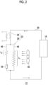
- Fig. 2 is a diagram schematically showing an example of the oil circulation line 20 of the compressor 12 according to the embodiment.
- the compressor 12 includes the compressor main body 16, the compressor cooling system 22, and the oil circulation line 20 connecting the compressor main body 16 and the compressor cooling system 22, as in the embodiment described with reference to Fig. 1 .
- the compressor cooling system 22 includes the liquid-cooled heat exchanger 24 and the air-cooled heat exchanger 26 and is configured to cool the oil circulation line 20.
- the liquid-cooled heat exchanger 24 and the air-cooled heat exchanger 26 are connected in series, and the liquid-cooled heat exchanger 24 is provided upstream of the air-cooled heat exchanger 26.
- the oil circulation line 20 branches into the first oil line 46 and the second oil line 48 upstream of the air-cooled heat exchanger 26, that is, between the liquid-cooled heat exchanger 24 and the air-cooled heat exchanger 26.
- the air-cooled heat exchanger 26 includes the cooling fan 50, and the first oil line 46 and the second oil line 48 are forcibly cooled by an airflow generated in the air-cooled heat exchanger 26 when the cooling fan 50 operates.
- the first oil line 46 and the second oil line 48 merge again downstream of the air-cooled heat exchanger 26, that is, between the air-cooled heat exchanger 26 and the oil inlet of the compressor main body 16.
- the air-cooled heat exchanger 26 may include an orifice 56 provided at at least one of the first oil line 46 and the second oil line 48 so that a difference between the flow rate of an oil of the first oil line 46 and the flow rate of an oil of the second oil line 48 is reduced.
- the flow rate of the oil of the second oil line 48 in a case where the orifice 56 does not exist is greater than that of the first oil line 46.
- the orifice 56 at the second oil line 48 the flow rate of the oil of the second oil line 48 can be reduced, and the flow rates of the oils of the first oil line 46 and the second oil line 48 can be made uniform.
- the imbalance of the flow rates of the oils of the first oil line 46 and the second oil line 48 can be eliminated, and efficiency of heat exchange of the air-cooled heat exchanger 26 can be improved.
- an aperture diameter R [m] of the orifice 56 may be selected from a range of 1.0 ⁇ 10 -4 (m) ⁇ R ⁇ 5.0 ⁇ 10 -2 (m).
- ⁇ denotes the viscosity [Pa ⁇ s] of an oil flowing into the air-cooled heat exchanger
- L 1 and L 2 denote lengths [m] of the first oil line 46 and the second oil line 48, which are the air-cooled heat exchangers, respectively
- d denotes a pipe diameter [m] of the first oil line 46 and the second oil line 48
- Q denotes the flow rate [m 3 /s] of an oil of the oil circulation line 20.
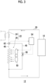
- Fig. 3 is a diagram schematically showing another example of the oil circulation line 20 of the compressor 12 according to the embodiment.
- the compressor 12 includes the compressor main body 16, the compressor cooling system 22, and the oil circulation line 20 connecting the compressor main body 16 and the compressor cooling system 22, as in the embodiment described with reference to Fig. 1 .
- the compressor cooling system 22 includes the liquid-cooled heat exchanger 24 and the air-cooled heat exchanger 26 and is configured to cool the oil circulation line 20.
- the liquid-cooled heat exchanger 24 and the air-cooled heat exchanger 26 are connected in series, and the liquid-cooled heat exchanger 24 is provided upstream of the air-cooled heat exchanger 26.
- the oil circulation line 20 branches into the first oil line 46 and the second oil line 48 upstream of the air-cooled heat exchanger 26, that is, between the liquid-cooled heat exchanger 24 and the air-cooled heat exchanger 26.
- the air-cooled heat exchanger 26 includes the cooling fan 50, and the first oil line 46 is forcibly cooled by an airflow generated in the air-cooled heat exchanger 26 when the cooling fan 50 operates.
- the first oil line 46 and the second oil line 48 merge again downstream of the air-cooled heat exchanger 26, that is, between the air-cooled heat exchanger 26 and the oil inlet of the compressor main body 16.
- the second oil line 48 bypasses the air-cooled heat exchanger 26, unlike the examples of Figs. 1 and 2 .
- the second oil line 48 is provided outside the air-cooled heat exchanger 26 in the compressor 12 and does not pass through the air-cooled heat exchanger 26.
- the second oil line 48 may include an on-off valve 58 operated to be closed when the cooling fan 50 is operated and to be opened when the cooling fan 50 is stopped.
- the fan controller 54 may be configured to receive, from at least one sensor, a sensor signal indicating a measurement result of the sensor and to operate the cooling fan 50 and the on-off valve 58 based on the measurement result.
- the fan controller 54 may close the on-off valve 58 while operating the cooling fan 50 and open the on-off valve 58 while stopping the cooling fan 50.
- Fig. 3 shows a case where a sensor signal of the second sensor 62 is input to the fan controller 54.
- another sensor for example, the first sensor 61, the third sensor 63, the fourth sensor 64, or the fifth sensor 65 may be used.
- the on-off valve 58 is closed to operate the air-cooled heat exchanger 26. In this manner, the defective cooling of the liquid-cooled heat exchanger 24 can be complemented or replaced by the air-cooled heat exchanger 26.
- a plurality of oil lines may be provided in the air-cooled heat exchanger 26, and the oil lines may be cooled by the cooling fan 50.
- the oil circulation line 20 branches into the first oil line 46 and the second oil line 48 in the air-cooled heat exchanger 26, but may branch into more oil lines, for example, three or four oil lines.
- the liquid-cooled heat exchanger 24 and the air-cooled heat exchanger 26 are connected in series in the compressor cooling system 22, and the liquid-cooled heat exchanger 24 is provided upstream of the air-cooled heat exchanger 26.
- the compressor cooling system 22 can have other configurations.
- liquid-cooled heat exchanger 24 and the air-cooled heat exchanger 26 may be connected in series, and the air-cooled heat exchanger 26 may be provided upstream of the liquid-cooled heat exchanger 24.
- the liquid-cooled heat exchanger 24 and the air-cooled heat exchanger 26 may be connected in parallel.
- the cooling fan 50 of the air-cooled heat exchanger 26 may generate an airflow in a direction opposite to the example described above and may be configured to blow air from the outside into the air-cooled heat exchanger 26.
- the cooling fan 50 may be configured to blow air to the refrigerant gas line 18, the first oil line 46, and the second oil line 48.
- the present invention can be used in the field of an oil lubrication-type compressor for a cryocooler.
Landscapes
- Engineering & Computer Science (AREA)
- Mechanical Engineering (AREA)
- General Engineering & Computer Science (AREA)
- Physics & Mathematics (AREA)
- Thermal Sciences (AREA)
- Compressor (AREA)
Abstract
Description
- The present invention relates to an oil lubrication-type compressor for a cryocooler.
- An oil-lubricated helium compressor with a dual aftercooler is proposed (for example, see PTL 1). Two aftercoolers that cool helium and an oil, that is, a water-cooled aftercooler and an air-cooled aftercooler are incorporated in the compressor. The air-cooled aftercooler is disposed in series or in parallel with the water-cooled aftercooler. By operating a fan of the air-cooled aftercooler, redundancy in a case where a cooling water circuit of the water-cooled aftercooler is blocked is provided.
- [PTL 1]
Japanese Unexamined Patent Publication No. 2019-505751 - The present inventor has studied the helium compressor described above and has recognized the following problems. Since the two heat exchangers including a water-cooled type and an air-cooled type are mounted on the compressor, the total length of an oil line to be cooled tends to be long, and the pressure loss of an oil flow can increase accordingly. A subsequent decrease in the flow rate of an oil can decrease the cooling capacity and can cause overheating of the compressor or a decrease in the life caused by a high-temperature operation. In particular, in a case where the temperature of cooling water supplied to the water-cooled heat exchanger is too low, the problem is likely to be manifested since oil viscosity can be nonlinearly increased at such a low temperature. As a possible measure, for example, it is conceivable to recover the flow rate of the oil by increasing input energy, such as driving an oil pump at high power. However, this is undesirable because power consumption is increased.
- An exemplary object of one embodiment of the present invention is to reduce a pressure loss of an oil line in an oil lubrication-type compressor for a cryocooler.
- According to an aspect of the present invention, there is provided an oil lubrication-type compressor for a cryocooler. The compressor for a cryocooler includes an air-cooled heat exchanger that includes a cooling fan and a first oil line disposed to be forcibly cooled by the cooling fan and a second oil line that bypasses the first oil line.
- With the present invention, the pressure loss of the oil line in the oil lubrication-type compressor for a cryocooler can be reduced.
-
-
Fig. 1 is a diagram schematically showing a cryocooler according to an embodiment. -
Fig. 2 is a diagram schematically showing an example of an oil circulation line of a compressor according to the embodiment. -
Fig. 3 is a diagram schematically showing another example of the oil circulation line of the compressor according to the embodiment. - Hereinafter, an embodiment for carrying out the present invention will be described in detail with reference to the drawings. In the description and drawings, the same or equivalent components, members, and processing will be assigned with the same reference symbols, and redundant description thereof will be omitted as appropriate. The scales and shapes of shown parts are set for convenience in order to make the description easy to understand and are not to be understood as limiting unless stated otherwise. The embodiment is merely an example and does not limit the scope of the present invention. All characteristics and combinations to be described in the embodiment are not necessarily essential to the invention.
-
Fig. 1 is a diagram schematically showing a cryocooler according to an embodiment. - A
cryocooler 10 includes an oil lubrication-type compressor for a cryocooler (hereinafter, also simply referred to as a compressor) 12 and acold head 14. Thecompressor 12 is configured to collect a refrigerant gas of thecryocooler 10 from thecold head 14, to pressurize the collected refrigerant gas, and to supply the refrigerant gas to thecold head 14 again. Thecompressor 12 is also referred to as a compressor unit. Thecold head 14 is also referred to as an expander and includes aroom temperature section 14a and a low-temperature section 14b which is also referred to as a cooling stage. Thecompressor 12 and thecold head 14 configure a refrigeration cycle of thecryocooler 10, and thereby the low-temperature section 14b is cooled to a desired cryogenic temperature. The refrigerant gas is also referred to as a working gas, and other suitable gases may be used although a helium gas is typically used. - Although the
cryocooler 10 is, for example, a single-stage or two-stage Gifford-McMahon (GM) cryocooler, thecryocooler 10 may be a pulse tube cryocooler, a Stirling cryocooler, or other types of cryocoolers. - Although the
cold head 14 has a different configuration depending on the type of thecryocooler 10, thecompressor 12 can use the configuration to be described below regardless of the type of thecryocooler 10. - In general, both a pressure of a refrigerant gas supplied from the
compressor 12 to thecold head 14 and a pressure of a refrigerant gas collected from thecold head 14 to thecompressor 12 are considerably higher than the atmospheric pressure and can be called a first high pressure and a second high pressure, respectively. For convenience of description, the first high pressure and the second high pressure are also simply called a high pressure and a low pressure, respectively. Typically, the high pressure is, for example, 2 to 3 MPa. The low pressure is, for example, 0.5 to 1.5 MPa and is, for example, approximately 0.8 MPa. - The
compressor 12 includes a compressormain body 16, arefrigerant gas line 18, anoil circulation line 20, and acompressor cooling system 22. InFig. 1 , in order to facilitate understanding, therefrigerant gas line 18 is shown by a solid line, and theoil circulation line 20 is shown by a broken line. Although details will be described later, thecompressor cooling system 22 is configured to include a liquid-cooledheat exchanger 24 and an air-cooledheat exchanger 26 and to cool therefrigerant gas line 18 and theoil circulation line 20. In addition, thecompressor 12 includes acompressor casing 28 that accommodates each of components of thecompressor 12, such as the compressormain body 16, therefrigerant gas line 18, theoil circulation line 20, and thecompressor cooling system 22. - The compressor
main body 16 is configured to internally compress a refrigerant gas sucked from a suction port thereof and to discharge the refrigerant gas from a discharge port. An oil is used in the compressormain body 16 for the sake of cooling and lubrication, and the sucked refrigerant gas is directly exposed to the oil in the compressormain body 16. Accordingly, the refrigerant gas is delivered from the discharge port in a state where the oil is slightly mixed. - The compressor
main body 16 may be, for example, a scroll type pump, a rotary type pump, or other pumps that pressurize a refrigerant gas. The compressormain body 16 may be configured to discharge the refrigerant gas at a fixed and constant flow rate. Alternatively, the compressormain body 16 may be configured to have a variable flow rate of the refrigerant gas to be discharged. The compressormain body 16 is called a compression capsule in some cases. - The
refrigerant gas line 18 includes adischarge port 30, asuction port 31, adischarge flow path 32, and asuction flow path 33. Thedischarge port 30 is an outlet of a refrigerant gas that is provided in thecompressor casing 28 in order to deliver the refrigerant gas, which is pressurized to a high pressure by the compressormain body 16, from thecompressor 12, and thesuction port 31 is an inlet of the refrigerant gas that is provided in thecompressor casing 28 in order for thecompressor 12 to receive the low-pressure refrigerant gas. Thecompressor casing 28 accommodates thedischarge flow path 32 and thesuction flow path 33. - The discharge port of the compressor
main body 16 is connected to thedischarge port 30 by thedischarge flow path 32, and thesuction port 31 is connected to the suction port of the compressormain body 16 by thesuction flow path 33. - The liquid-cooled
heat exchanger 24 and the air-cooledheat exchanger 26 that configure thecompressor cooling system 22 are provided at thedischarge flow path 32. In addition, anoil separator 34 and anadsorber 35 are provided downstream of thecompressor cooling system 22 at thedischarge flow path 32. - The
oil separator 34 is provided in order to separate an oil, which is mixed in a refrigerant gas as passing through the compressormain body 16, out from the refrigerant gas. Theadsorber 35 is provided in order to remove, for example, a vaporized oil and other contaminants remaining in the refrigerant gas from the refrigerant gas through adsorption. Theoil separator 34 and theadsorber 35 are connected in series. In thedischarge flow path 32, theoil separator 34 is disposed on a compressormain body 16 side, and theadsorber 35 is disposed on adischarge port 30 side. - An
oil return line 21 that connects theoil separator 34 to the compressormain body 16 is provided. An oil collected by theoil separator 34 can return to the compressormain body 16 through theoil return line 21. In the middle of theoil return line 21, a filter that removes dust included in the oil separated out by theoil separator 34 and an orifice that controls the amount of the oil returning to the compressormain body 16 may be provided. - On the other hand, a
storage tank 36 is provided at thesuction flow path 33. Thestorage tank 36 is provided as a volume for removing pulsation included in a low-pressure refrigerant gas returning from thecold head 14 to thecompressor 12. - In addition, a
bypass valve 38 that connects thedischarge flow path 32 to thesuction flow path 33 to bypass the compressormain body 16 is provided at therefrigerant gas line 18. For example, thebypass valve 38 branches off from thedischarge flow path 32 between theoil separator 34 and theadsorber 35 and is connected to thesuction flow path 33 between the compressormain body 16 and thestorage tank 36. Thebypass valve 38 is provided in order to control a flow rate of a refrigerant gas and/or in order to equalize thedischarge flow path 32 and thesuction flow path 33 when thecompressor 12 is stopped. - The
refrigerant gas line 18 of thecompressor 12 is connected to thecold head 14. - A high-
pressure port 40 and a low-pressure port 41 are provided in theroom temperature section 14a of thecold head 14. The high-pressure port 40 is connected to thedischarge port 30 by a high-pressure pipe 42, and the low-pressure port 41 is connected to thesuction port 31 by a low-pressure pipe 43. - The
oil circulation line 20 connects an oil outlet to an oil inlet of the compressormain body 16 via the compressor cooling system 22 (that is, the liquid-cooledheat exchanger 24 and the air-cooled heat exchanger 26). Accordingly, an oil flowing out from the compressormain body 16 can be cooled by thecompressor cooling system 22 and flow into the compressormain body 16 again. - In the embodiment, the
oil circulation line 20 branches into a plurality of (two in the example) oil flow paths at thecompressor cooling system 22 as will be described later. The branched oil flow paths merge between thecompressor cooling system 22 and the oil inlet of the compressormain body 16 again. - An orifice that controls a flow rate of an oil flowing inside may be provided at the
oil circulation line 20. In addition, a filter that removes dust included in the oil may be provided at theoil circulation line 20. Such an orifice and such a filter may be provided, for example, on a downstream side of theoil circulation line 20, that is, between thecompressor cooling system 22 and the oil inlet of the compressormain body 16. - As described above, the
compressor cooling system 22 includes the liquid-cooledheat exchanger 24 and the air-cooledheat exchanger 26. The liquid-cooledheat exchanger 24 and the air-cooledheat exchanger 26 are connected in series, and the liquid-cooledheat exchanger 24 is provided upstream of the air-cooledheat exchanger 26. Accordingly, an oil heated by compression heat generated with compression of a refrigerant gas in the compressormain body 16 and a high-pressure refrigerant gas initially flow from the compressormain body 16 into the liquid-cooledheat exchanger 24 to be cooled and then flow into the air-cooledheat exchanger 26. - In the embodiment, the liquid-cooled
heat exchanger 24 is mounted on thecompressor 12 as a main cooling device of thecompressor 12, and the air-cooledheat exchanger 26 is mounted on thecompressor 12 as a backup cooling device of thecompressor 12. Accordingly, the liquid-cooledheat exchanger 24 operates at all times during an operation of thecompressor 12, and the air-cooledheat exchanger 26 does not operate when the liquid-cooledheat exchanger 24 operates normally, but may operate when the liquid-cooledheat exchanger 24 does not operate due to a failure or the like when a cooling capacity thereof has decreased. Thus, as will be described later, the air-cooledheat exchanger 26 may be configured to switch on or off based on an output of a sensor provided at thecompressor 12, such as a temperature sensor for an oil or a refrigerant gas. - The liquid-cooled
heat exchanger 24 includes afirst portion 24a that cools a refrigerant gas through heat exchange between the refrigerant gas and a coolant and asecond portion 24b that cools an oil through heat exchange between the oil and the coolant. Thefirst portion 24a is disposed between the compressormain body 16 and theoil separator 34 at thedischarge flow path 32, more specifically, between the discharge port of the compressormain body 16 and the air-cooledheat exchanger 26 and cools the refrigerant gas flowing in thedischarge flow path 32. Thesecond portion 24b is disposed between the oil outlet of the compressormain body 16 and the air-cooledheat exchanger 26 at theoil circulation line 20 and cools the oil flowing in theoil circulation line 20. - Although water (for example, tap water, industrial water, and the like) is typically used as a coolant, other suitable coolants may be used. The coolant is supplied to the
compressor 12 from the outside and is exhausted to the outside of thecompressor 12 via thefirst portion 24a and thesecond portion 24b of the liquid-cooledheat exchanger 24. In this manner, compression heat generated by the compressormain body 16 is removed to the outside of thecompressor 12 together with the coolant. The coolant may be cooled by, for example, a coolant circulation device (not shown) such as a known water chiller and may be supplied to thecompressor 12 again. - The air-cooled
heat exchanger 26 includes a coolingfan 50, afirst oil line 46 that is disposed to be forcibly cooled by the coolingfan 50, and asecond oil line 48 that bypasses thefirst oil line 46 and that is disposed to be forcibly cooled by the coolingfan 50. - The
first oil line 46 and thesecond oil line 48 are a portion of theoil circulation line 20 disposed in the air-cooledheat exchanger 26. Thesecond oil line 48 branches off from theoil circulation line 20 upstream of the air-cooledheat exchanger 26, that is, between the liquid-cooledheat exchanger 24 and the air-cooledheat exchanger 26 and merges with thefirst oil line 46 again downstream of the air-cooledheat exchanger 26, that is, between the air-cooledheat exchanger 26 and the oil inlet of the compressormain body 16. - As an exemplary configuration, the cooling
fan 50 is provided in thecompressor casing 28 to exhaust air from the air-cooledheat exchanger 26 to the outside as the coolingfan 50 operates. - Two
air intakes 52 are provided at a portion of thecompressor casing 28 surrounding the air-cooledheat exchanger 26, and air is taken into the air-cooledheat exchanger 26 through the air intakes 52 from the outside as the coolingfan 50 operates. One airflow that blows from oneair intake 52 into the air-cooledheat exchanger 26 is used in forced cooling of therefrigerant gas line 18 and thefirst oil line 46, and another airflow that blows from theother air intake 52 into the air-cooledheat exchanger 26 is used in forced cooling of thesecond oil line 48. InFig. 1 , for the sake of understanding, the airflows are schematically shown by thick arrows. - As will be described later, the cooling
fan 50 may operate based on an oil temperature measured by an oil temperature sensor. Alternatively, the coolingfan 50 may operate based on a refrigerant gas temperature measured by a refrigerant gas temperature sensor. - During an operation of the
cryocooler 10, a refrigerant gas collected from thecold head 14 to thecompressor 12 flows from the low-pressure port 41 into thesuction port 31 of thecompressor 12 through the low-pressure pipe 43. The refrigerant gas is collected to the suction port of the compressormain body 16 via thestorage tank 36 on thesuction flow path 33. The refrigerant gas is compressed and pressurized by the compressormain body 16. The refrigerant gas delivered from the discharge port of the compressormain body 16 is cooled by the liquid-cooledheat exchanger 24 and the air-cooledheat exchanger 26 and exits thecompressor 12 from thedischarge port 30 via theoil separator 34 and theadsorber 35. The refrigerant gas is supplied into thecold head 14 via the high-pressure pipe 42 and the high-pressure port 40. - An oil flowing out from the oil outlet of the compressor
main body 16 flows into the liquid-cooledheat exchanger 24 through theoil circulation line 20 and is cooled through heat exchange between the oil and a coolant at the liquid-cooledheat exchanger 24. The cooled oil flows from the liquid-cooledheat exchanger 24 into the air-cooledheat exchanger 26. The oil branches off and flows to thefirst oil line 46 and thesecond oil line 48 in the air-cooledheat exchanger 26. In a case where the coolingfan 50 operates, the oil is cooled with air when flowing in thefirst oil line 46 and thesecond oil line 48. The oil flowing out from the air-cooledheat exchanger 26 returns to the oil inlet of the compressormain body 16 through theoil circulation line 20. - The
compressor 12 may be provided with various types of sensors. For example, thecompressor 12 may include at least one oil temperature sensor (61 to 63) that measures the temperature of an oil. Thefirst sensor 61 is provided upstream of the liquid-cooledheat exchanger 24 on theoil circulation line 20 and measures the temperature of the oil flowing from the compressormain body 16 into the liquid-cooledheat exchanger 24. Thesecond sensor 62 is provided downstream of the liquid-cooledheat exchanger 24 on theoil circulation line 20, specifically, between the liquid-cooledheat exchanger 24 and the air-cooledheat exchanger 26 and measures the temperature of the oil flowing from the liquid-cooledheat exchanger 24 into the air-cooledheat exchanger 26. Thethird sensor 63 is provided downstream of the air-cooledheat exchanger 26 on theoil circulation line 20 and measures the temperature of the oil flowing from the air-cooledheat exchanger 26 into the compressormain body 16. The temperature sensor may be, for example, a thermistor. - The
compressor 12 may include at least one refrigerant gas sensor (64 to 66) that measures the temperature of a refrigerant gas. Afourth sensor 64 is provided upstream of the liquid-cooledheat exchanger 24 on thedischarge flow path 32 of therefrigerant gas line 18 and measures the temperature of the refrigerant gas flowing from the compressormain body 16 into the liquid-cooledheat exchanger 24. Afifth sensor 65 is provided downstream of the liquid-cooledheat exchanger 24 on therefrigerant gas line 18, specifically, between the liquid-cooledheat exchanger 24 and the air-cooledheat exchanger 26 and measures the temperature of the refrigerant gas flowing from the liquid-cooledheat exchanger 24 into the air-cooledheat exchanger 26. Asixth sensor 66 is provided downstream of the air-cooledheat exchanger 26 on therefrigerant gas line 18 and measures the temperature of the refrigerant gas flowing from the air-cooledheat exchanger 26 into theoil separator 34. - The air-cooled
heat exchanger 26 may be provided with afan controller 54 that turns the coolingfan 50 on and off. Thefan controller 54 is configured to receive, from at least one sensor, a sensor signal indicating a measurement result of the sensor and to operate the coolingfan 50 based on the measurement result. For example,Fig. 1 shows a case where a sensor signal of thesecond sensor 62 is input to thefan controller 54. - The
fan controller 54 is realized by an element or a circuit including a CPU and a memory of a computer as a hardware configuration and is realized by a computer program as a software configuration, but is shown in the drawings as a functional block realized in cooperation therewith as appropriate. It is clear for those skilled in the art that the functional blocks can be realized in various manners in combination with hardware and software. - For example, the
fan controller 54 may operate the coolingfan 50 based on an oil temperature measured by at least one of the oil temperature sensors (61 to 63). In this case, thefan controller 54 receives a sensor signal indicating a measured temperature of an oil from thefirst sensor 61, thesecond sensor 62, or thethird sensor 63 and compares the measured temperature with a temperature threshold value. The temperature threshold value is set to a value at which it is evaluated that the oil is insufficiently cooled in a case where the oil temperature is higher than the threshold value. - As one cause that an oil temperature measured by the oil temperature sensor exceeds the temperature threshold value, for example, a case where the temperature of a coolant supplied to the liquid-cooled
heat exchanger 24 is too high (that is, defective cooling or a failure of a chiller that cools the coolant) or a defect of the liquid-cooledheat exchanger 24 itself (clogging or damage of the heat exchanger) is assumed. - Therefore, the
fan controller 54 operates the air-cooledheat exchanger 26 in a case where a measured temperature exceeds the temperature threshold value. That is, thefan controller 54 switches the coolingfan 50 from off to on to activate the air-cooledheat exchanger 26. On the other hand, in a case where the measured temperature does not exceed the temperature threshold value, thefan controller 54 does not activate the air-cooled heat exchanger 26 (keeps the coolingfan 50 off). In this manner, as the air-cooledheat exchanger 26, which is the backup cooling device of thecompressor 12, is operated, a defective operation of the liquid-cooledheat exchanger 24, which is the main cooling device of thecompressor 12, can be dealt with. - Alternatively, the
fan controller 54 may operate the coolingfan 50 based on a refrigerant gas temperature measured by the refrigerant gas temperature sensor. For example, thefan controller 54 may receive a sensor signal indicating a measured temperature of a refrigerant gas from thefourth sensor 64 or thefifth sensor 65 and compare the measured temperature with the temperature threshold value. Thefan controller 54 operates the air-cooledheat exchanger 26 in a case where the measured temperature exceeds the temperature threshold value but does not activate the air-cooledheat exchanger 26 in a case where the measured temperature does not exceed the temperature threshold value. Even in this manner, it is possible to deal with the defective operation of the liquid-cooledheat exchanger 24 using the air-cooledheat exchanger 26. - Meanwhile, one of main applications of the
cryocooler 10 is to cool a superconducting magnet. Typically, the superconducting magnet is cooled by being immersed in a large amount of liquid helium, and thecryocooler 10 is used in cooling and recondensing the liquid helium. In such a device of the related art, even when thecryocooler 10 is stopped, the cooling of the superconducting magnet can be maintained for a while with a large amount of liquid helium. On the other hand, in recent years, research and development of a superconducting magnet that greatly reduces the amount of liquid helium used has been advanced against a backdrop of a surge in helium prices. In such a helium-saving type superconducting device, the stop of the operation of thecryocooler 10 is likely to lead to the loss of the cooling of the superconducting magnet. - According to the embodiment, since the
compressor cooling system 22 includes the liquid-cooledheat exchanger 24 and the air-cooledheat exchanger 26, redundancy related to the cooling of thecompressor 12 is secured. Even when a defective operation occurs in the liquid-cooledheat exchanger 24, a cooling function of thecompressor 12 can be complemented or replaced by the air-cooledheat exchanger 26. Accordingly, a risk of an excessive temperature rise of thecompressor 12 and the subsequent stop of the operation of thecryocooler 10 is reduced. Therefore, thecryocooler 10 according to the embodiment is useful for improving continuity of the operation of a so-called helium-saving type superconducting device. - However, in the embodiment, since two heat exchangers of the liquid-cooled type and the air-cooled type are mounted on the compressor cooling system 22 (in particular, the liquid-cooled
heat exchanger 24 and the air-cooledheat exchanger 26 are connected in series), the total length of theoil circulation line 20 to be cooled tends to be long, and the pressure loss of an oil flow can increase accordingly. A subsequent decrease in the flow rate of an oil of theoil circulation line 20 can decrease the cooling capacity of thecompressor cooling system 22 and can cause overheating of thecompressor 12 or a decrease in the life caused by a high-temperature operation. In particular, in a case where the temperature of a coolant supplied to the liquid-cooledheat exchanger 24 is too low, the problem is likely to be manifested since oil viscosity can be nonlinearly increased at such a low temperature. As a possible measure, for example, it is conceivable to recover the flow rate of the oil of theoil circulation line 20 by increasing input energy, such as driving an oil pump at high power. However, this is undesirable because power consumption is increased. - In order to deal with this, in the embodiment, the air-cooled
heat exchanger 26 further includes thesecond oil line 48 that bypasses thefirst oil line 46, instead of including only thefirst oil line 46. In this manner, as a plurality of oil flow paths are provided in parallel at the air-cooledheat exchanger 26, the flow path sectional area of theoil circulation line 20 can be increased, and the pressure loss can be reduced. Even when an oil is cooled to a low temperature by the liquid-cooledheat exchanger 24 and the viscosity of the oil exiting from the liquid-cooledheat exchanger 24 is increased, a decrease in the flow rate of the oil flowing in the air-cooledheat exchanger 26 can be suppressed. It is possible to prevent insufficiency of the flow rate of the oil circulating in theoil circulation line 20 and to avoid defective cooling of thecompressor 12. -
Fig. 2 is a diagram schematically showing an example of theoil circulation line 20 of thecompressor 12 according to the embodiment. Also in the example ofFig. 2 , thecompressor 12 includes the compressormain body 16, thecompressor cooling system 22, and theoil circulation line 20 connecting the compressormain body 16 and thecompressor cooling system 22, as in the embodiment described with reference toFig. 1 . Thecompressor cooling system 22 includes the liquid-cooledheat exchanger 24 and the air-cooledheat exchanger 26 and is configured to cool theoil circulation line 20. The liquid-cooledheat exchanger 24 and the air-cooledheat exchanger 26 are connected in series, and the liquid-cooledheat exchanger 24 is provided upstream of the air-cooledheat exchanger 26. - The
oil circulation line 20 branches into thefirst oil line 46 and thesecond oil line 48 upstream of the air-cooledheat exchanger 26, that is, between the liquid-cooledheat exchanger 24 and the air-cooledheat exchanger 26. The air-cooledheat exchanger 26 includes the coolingfan 50, and thefirst oil line 46 and thesecond oil line 48 are forcibly cooled by an airflow generated in the air-cooledheat exchanger 26 when the coolingfan 50 operates. Thefirst oil line 46 and thesecond oil line 48 merge again downstream of the air-cooledheat exchanger 26, that is, between the air-cooledheat exchanger 26 and the oil inlet of the compressormain body 16. - The air-cooled
heat exchanger 26 may include anorifice 56 provided at at least one of thefirst oil line 46 and thesecond oil line 48 so that a difference between the flow rate of an oil of thefirst oil line 46 and the flow rate of an oil of thesecond oil line 48 is reduced. In the example ofFig. 2 , the flow rate of the oil of thesecond oil line 48 in a case where theorifice 56 does not exist is greater than that of thefirst oil line 46. - Therefore, by providing the
orifice 56 at thesecond oil line 48, the flow rate of the oil of thesecond oil line 48 can be reduced, and the flow rates of the oils of thefirst oil line 46 and thesecond oil line 48 can be made uniform. The imbalance of the flow rates of the oils of thefirst oil line 46 and thesecond oil line 48 can be eliminated, and efficiency of heat exchange of the air-cooledheat exchanger 26 can be improved. - According to the study of the inventor, an aperture diameter R [m] of the
orifice 56 may be selected from a range of 1.0 × 10⁻⁴(m) ≤ R ≤ 5.0 × 10⁻²(m). Herein, the aperture diameter R can be calculated by the following equation.
- Herein, µ denotes the viscosity [Pa·s] of an oil flowing into the air-cooled heat exchanger, L1 and L2 denote lengths [m] of the
first oil line 46 and thesecond oil line 48, which are the air-cooled heat exchangers, respectively, d denotes a pipe diameter [m] of thefirst oil line 46 and thesecond oil line 48, and Q denotes the flow rate [m3/s] of an oil of theoil circulation line 20. -
Fig. 3 is a diagram schematically showing another example of theoil circulation line 20 of thecompressor 12 according to the embodiment. Also in the example ofFig. 3 , thecompressor 12 includes the compressormain body 16, thecompressor cooling system 22, and theoil circulation line 20 connecting the compressormain body 16 and thecompressor cooling system 22, as in the embodiment described with reference toFig. 1 . Thecompressor cooling system 22 includes the liquid-cooledheat exchanger 24 and the air-cooledheat exchanger 26 and is configured to cool theoil circulation line 20. The liquid-cooledheat exchanger 24 and the air-cooledheat exchanger 26 are connected in series, and the liquid-cooledheat exchanger 24 is provided upstream of the air-cooledheat exchanger 26. - The
oil circulation line 20 branches into thefirst oil line 46 and thesecond oil line 48 upstream of the air-cooledheat exchanger 26, that is, between the liquid-cooledheat exchanger 24 and the air-cooledheat exchanger 26. The air-cooledheat exchanger 26 includes the coolingfan 50, and thefirst oil line 46 is forcibly cooled by an airflow generated in the air-cooledheat exchanger 26 when the coolingfan 50 operates. Thefirst oil line 46 and thesecond oil line 48 merge again downstream of the air-cooledheat exchanger 26, that is, between the air-cooledheat exchanger 26 and the oil inlet of the compressormain body 16. - However, the
second oil line 48 bypasses the air-cooledheat exchanger 26, unlike the examples ofFigs. 1 and2 . Thesecond oil line 48 is provided outside the air-cooledheat exchanger 26 in thecompressor 12 and does not pass through the air-cooledheat exchanger 26. - The
second oil line 48 may include an on-offvalve 58 operated to be closed when the coolingfan 50 is operated and to be opened when the coolingfan 50 is stopped. - Therefore, the
fan controller 54 may be configured to receive, from at least one sensor, a sensor signal indicating a measurement result of the sensor and to operate the coolingfan 50 and the on-offvalve 58 based on the measurement result. Thefan controller 54 may close the on-offvalve 58 while operating the coolingfan 50 and open the on-offvalve 58 while stopping the coolingfan 50. For example,Fig. 3 shows a case where a sensor signal of thesecond sensor 62 is input to thefan controller 54. As described above, another sensor (for example, thefirst sensor 61, thethird sensor 63, thefourth sensor 64, or the fifth sensor 65) may be used. - In this manner, when the liquid-cooled
heat exchanger 24 which is the main cooling device of thecompressor 12, operates normally, the air-cooledheat exchanger 26, which is the backup cooling device, is stopped, and an oil cooled by the liquid-cooledheat exchanger 24 flows in thesecond oil line 48. As an oil flow bypasses the air-cooledheat exchanger 26, an increase in the pressure loss of theoil circulation line 20 can be suppressed. It is possible to prevent insufficiency of the flow rate of the oil circulating in theoil circulation line 20 and to avoid defective cooling of thecompressor 12. - On the other hand, when the liquid-cooled
heat exchanger 24 does not operate normally, the on-offvalve 58 is closed to operate the air-cooledheat exchanger 26. In this manner, the defective cooling of the liquid-cooledheat exchanger 24 can be complemented or replaced by the air-cooledheat exchanger 26. - In the example of
Fig. 3 , as in the examples ofFigs. 1 and2 , a plurality of oil lines may be provided in the air-cooledheat exchanger 26, and the oil lines may be cooled by the coolingfan 50. - The present invention has been described based on the example. It is clear for those skilled in the art that the present invention is not limited to the embodiment, various design changes are possible, various modification examples are possible, and such modification examples are also within the scope of the present invention. Various characteristics described in relation to one embodiment are also applicable to other embodiments. A new embodiment generated through combination also has the effects of each of the combined embodiments.
- In the embodiment described above, the
oil circulation line 20 branches into thefirst oil line 46 and thesecond oil line 48 in the air-cooledheat exchanger 26, but may branch into more oil lines, for example, three or four oil lines. - In the embodiment described above, the liquid-cooled
heat exchanger 24 and the air-cooledheat exchanger 26 are connected in series in thecompressor cooling system 22, and the liquid-cooledheat exchanger 24 is provided upstream of the air-cooledheat exchanger 26. However, thecompressor cooling system 22 can have other configurations. - For example, the liquid-cooled
heat exchanger 24 and the air-cooledheat exchanger 26 may be connected in series, and the air-cooledheat exchanger 26 may be provided upstream of the liquid-cooledheat exchanger 24. Alternatively, the liquid-cooledheat exchanger 24 and the air-cooledheat exchanger 26 may be connected in parallel. - The cooling
fan 50 of the air-cooledheat exchanger 26 may generate an airflow in a direction opposite to the example described above and may be configured to blow air from the outside into the air-cooledheat exchanger 26. The coolingfan 50 may be configured to blow air to therefrigerant gas line 18, thefirst oil line 46, and thesecond oil line 48. - Although the present invention has been described using specific phrases based on the embodiment, the embodiment merely shows one aspect of the principles and applications of the present invention, and many modification examples and changes in disposition are allowed without departing from the concept of the present invention specified in the claims.
- The present invention can be used in the field of an oil lubrication-type compressor for a cryocooler.
-
- 10
- cryocooler
- 12
- compressor
- 18
- refrigerant gas line
- 24
- liquid-cooled heat exchanger
- 26
- air-cooled heat exchanger
- 46
- first oil line
- 48
- second oil line
- 50
- cooling fan
- 56
- orifice
- 58
- on-off valve
Claims (9)
- An oil lubrication-type compressor for a cryocooler comprising:an air-cooled heat exchanger that includes a cooling fan and a first oil line disposed to be forcibly cooled by the cooling fan; anda second oil line that bypasses the first oil line.
- The oil lubrication-type compressor for a cryocooler according to claim 1,
wherein the second oil line is disposed to be forcibly cooled by the cooling fan. - The oil lubrication-type compressor for a cryocooler according to claim 2,
wherein the air-cooled heat exchanger includes an orifice provided at at least one of the first oil line and the second oil line so that a difference between a flow rate of an oil of the first oil line and a flow rate of an oil of the second oil line is reduced. - The oil lubrication-type compressor for a cryocooler according to claim 1,
wherein the second oil line bypasses the air-cooled heat exchanger. - The oil lubrication-type compressor for a cryocooler according to claim 4,
wherein the second oil line includes an on-off valve that operates to be closed when the cooling fan is operated and to be opened when the cooling fan is stopped. - The oil lubrication-type compressor for a cryocooler according to claim 1,
wherein the air-cooled heat exchanger cools a refrigerant gas line. - The oil lubrication-type compressor for a cryocooler according to any one of claims 1 to 6, further comprising:
a liquid-cooled heat exchanger that is connected in series upstream of the air-cooled heat exchanger. - The oil lubrication-type compressor for a cryocooler according to claim 7, further comprising:an oil temperature sensor that is provided upstream or downstream of the liquid-cooled heat exchanger or that is provided downstream of the air-cooled heat exchanger,wherein the cooling fan operates based on an oil temperature measured by the oil temperature sensor.
- The oil lubrication-type compressor for a cryocooler according to claim 7,wherein the liquid-cooled heat exchanger further includes a refrigerant gas temperature sensor that is provided upstream or downstream of the liquid-cooled heat exchanger on a refrigerant gas line, andthe cooling fan operates based on a refrigerant gas temperature measured by the refrigerant gas temperature sensor.
Applications Claiming Priority (2)
| Application Number | Priority Date | Filing Date | Title |
|---|---|---|---|
| JP2022078318A JP2023167267A (en) | 2022-05-11 | 2022-05-11 | Oil lubrication type compressor for cryogenic refrigerator |
| PCT/JP2023/015355 WO2023218865A1 (en) | 2022-05-11 | 2023-04-17 | Oil lubrication-type compressor for cryocooler |
Publications (3)
| Publication Number | Publication Date |
|---|---|
| EP4524494A1 true EP4524494A1 (en) | 2025-03-19 |
| EP4524494A4 EP4524494A4 (en) | 2025-06-11 |
| EP4524494B1 EP4524494B1 (en) | 2026-05-06 |
Family
ID=88730244
Family Applications (1)
| Application Number | Title | Priority Date | Filing Date |
|---|---|---|---|
| EP23803347.6A Active EP4524494B1 (en) | 2022-05-11 | 2023-04-17 | Oil lubrication-type compressor for cryocooler |
Country Status (5)
| Country | Link |
|---|---|
| US (1) | US20250043999A1 (en) |
| EP (1) | EP4524494B1 (en) |
| JP (1) | JP2023167267A (en) |
| CN (1) | CN119032245A (en) |
| WO (1) | WO2023218865A1 (en) |
Families Citing this family (1)
| Publication number | Priority date | Publication date | Assignee | Title |
|---|---|---|---|---|
| KR20250159507A (en) * | 2024-05-02 | 2025-11-11 | 한국수력원자력 주식회사 | method and system for removing impurities of helium gas refrigerator |
Family Cites Families (4)
| Publication number | Priority date | Publication date | Assignee | Title |
|---|---|---|---|---|
| DE3023925A1 (en) * | 1980-06-26 | 1982-01-14 | Leybold-Heraeus GmbH, 5000 Köln | Helium compressor for cryogenic refrigeration - has separate and detachable cooling water system to give choice of operating modes |
| US8978400B2 (en) * | 2009-11-09 | 2015-03-17 | Sumitomo (Shi) Cryogenics Of America Inc. | Air cooled helium compressor |
| US20170175743A1 (en) * | 2015-12-18 | 2017-06-22 | Sumitomo (Shi) Cryogenics Of America, Inc. | Cold start helium compressor |
| US10240832B2 (en) * | 2015-12-18 | 2019-03-26 | Sumitomo (Shi) Cryogenic Of America, Inc | Helium compressor with dual after-coolers |
-
2022
- 2022-05-11 JP JP2022078318A patent/JP2023167267A/en active Pending
-
2023
- 2023-04-17 CN CN202380034525.4A patent/CN119032245A/en active Pending
- 2023-04-17 EP EP23803347.6A patent/EP4524494B1/en active Active
- 2023-04-17 WO PCT/JP2023/015355 patent/WO2023218865A1/en not_active Ceased
-
2024
- 2024-10-18 US US18/919,441 patent/US20250043999A1/en active Pending
Also Published As
| Publication number | Publication date |
|---|---|
| US20250043999A1 (en) | 2025-02-06 |
| CN119032245A (en) | 2024-11-26 |
| JP2023167267A (en) | 2023-11-24 |
| WO2023218865A1 (en) | 2023-11-16 |
| EP4524494A4 (en) | 2025-06-11 |
| EP4524494B1 (en) | 2026-05-06 |
Similar Documents
| Publication | Publication Date | Title |
|---|---|---|
| JP6078361B2 (en) | air compressor | |
| US6698234B2 (en) | Method for increasing efficiency of a vapor compression system by evaporator heating | |
| CN113597511B (en) | Compressor system and control method thereof | |
| US6658888B2 (en) | Method for increasing efficiency of a vapor compression system by compressor cooling | |
| US11649990B2 (en) | Compressor system for cryocooler and auxiliary cooling device | |
| KR102108239B1 (en) | Helium compressor with double aftercooler | |
| EP3913300A1 (en) | Method for starting cryogenic freezer and cryogenic freezer | |
| US20250043999A1 (en) | Oil lubrication-type compressor for cryocooler | |
| JP4641129B2 (en) | Fail-safe oil-lubricated helium compressor that supplies oil-free gas | |
| KR102108241B1 (en) | Double helium compressor | |
| ES2425226T3 (en) | Refrigerant system with steam injection and liquid injection through independent passageways | |
| CN114811991A (en) | Super-current helium refrigerator with independent load test cold box | |
| CN114923291A (en) | Overflow helium refrigerator with negative pressure protection module | |
| US11649998B2 (en) | Cryocooler | |
| EP4033098A1 (en) | Heat recovery device | |
| JP5470064B2 (en) | Two-stage compressor | |
| EP4357696B1 (en) | Oil-lubricated cryocooler compressor and operation method thereof | |
| TW202006251A (en) | Cryopump system and method for operating cryopump system | |
| JP4109997B2 (en) | Turbo refrigerator | |
| JP2910499B2 (en) | Refrigeration equipment | |
| EP4467896A1 (en) | Cryocooler and method for operating cryocooler | |
| EP4722536A1 (en) | Gas compressor | |
| CN122029359A (en) | Waste heat recovery system, waste heat recovery unit, and waste heat recovery method | |
| CN118525175A (en) | Refrigeration unit | |
| HK1138353A (en) | Refrigerant system with economizer, intercooler and multi-stage compressor |
Legal Events
| Date | Code | Title | Description |
|---|---|---|---|
| STAA | Information on the status of an ep patent application or granted ep patent |
Free format text: STATUS: THE INTERNATIONAL PUBLICATION HAS BEEN MADE |
|
| PUAI | Public reference made under article 153(3) epc to a published international application that has entered the european phase |
Free format text: ORIGINAL CODE: 0009012 |
|
| STAA | Information on the status of an ep patent application or granted ep patent |
Free format text: STATUS: REQUEST FOR EXAMINATION WAS MADE |
|
| 17P | Request for examination filed |
Effective date: 20241009 |
|
| AK | Designated contracting states |
Kind code of ref document: A1 Designated state(s): AL AT BE BG CH CY CZ DE DK EE ES FI FR GB GR HR HU IE IS IT LI LT LU LV MC ME MK MT NL NO PL PT RO RS SE SI SK SM TR |
|
| STAA | Information on the status of an ep patent application or granted ep patent |
Free format text: STATUS: EXAMINATION IS IN PROGRESS |
|
| A4 | Supplementary search report drawn up and despatched |
Effective date: 20250514 |
|
| RIC1 | Information provided on ipc code assigned before grant |
Ipc: F25B 31/00 20060101ALI20250508BHEP Ipc: F25B 40/02 20060101ALI20250508BHEP Ipc: F25B 9/14 20060101ALI20250508BHEP Ipc: F04D 29/58 20060101ALI20250508BHEP Ipc: F04C 29/04 20060101ALI20250508BHEP Ipc: F04C 29/02 20060101ALI20250508BHEP Ipc: F25B 1/00 20060101ALI20250508BHEP Ipc: F25B 9/00 20060101AFI20250508BHEP |
|
| 17Q | First examination report despatched |
Effective date: 20250526 |
|
| DAV | Request for validation of the european patent (deleted) | ||
| DAX | Request for extension of the european patent (deleted) | ||
| GRAP | Despatch of communication of intention to grant a patent |
Free format text: ORIGINAL CODE: EPIDOSNIGR1 |
|
| STAA | Information on the status of an ep patent application or granted ep patent |
Free format text: STATUS: GRANT OF PATENT IS INTENDED |
|
| INTG | Intention to grant announced |
Effective date: 20251218 |
|
| GRAS | Grant fee paid |
Free format text: ORIGINAL CODE: EPIDOSNIGR3 |
|
| GRAA | (expected) grant |
Free format text: ORIGINAL CODE: 0009210 |
|
| STAA | Information on the status of an ep patent application or granted ep patent |
Free format text: STATUS: THE PATENT HAS BEEN GRANTED |
|
| AK | Designated contracting states |
Kind code of ref document: B1 Designated state(s): AL AT BE BG CH CY CZ DE DK EE ES FI FR GB GR HR HU IE IS IT LI LT LU LV MC ME MK MT NL NO PL PT RO RS SE SI SK SM TR |
|
| REG | Reference to a national code |
Ref country code: CH Ref legal event code: F10 Free format text: ST27 STATUS EVENT CODE: U-0-0-F10-F00 (AS PROVIDED BY THE NATIONAL OFFICE) Effective date: 20260506 Ref country code: GB Ref legal event code: FG4D |