EP4524470A1 - Gas turbine engine and fuel nozzle therefor - Google Patents
Gas turbine engine and fuel nozzle therefor Download PDFInfo
- Publication number
- EP4524470A1 EP4524470A1 EP24189371.8A EP24189371A EP4524470A1 EP 4524470 A1 EP4524470 A1 EP 4524470A1 EP 24189371 A EP24189371 A EP 24189371A EP 4524470 A1 EP4524470 A1 EP 4524470A1
- Authority
- EP
- European Patent Office
- Prior art keywords
- shaft
- flange
- casing
- disposed
- turbine engine
- Prior art date
- Legal status (The legal status is an assumption and is not a legal conclusion. Google has not performed a legal analysis and makes no representation as to the accuracy of the status listed.)
- Pending
Links
Images







Classifications
-
- F—MECHANICAL ENGINEERING; LIGHTING; HEATING; WEAPONS; BLASTING
- F23—COMBUSTION APPARATUS; COMBUSTION PROCESSES
- F23R—GENERATING COMBUSTION PRODUCTS OF HIGH PRESSURE OR HIGH VELOCITY, e.g. GAS-TURBINE COMBUSTION CHAMBERS
- F23R3/00—Continuous combustion chambers using liquid or gaseous fuel
- F23R3/28—Continuous combustion chambers using liquid or gaseous fuel characterised by the fuel supply
- F23R3/283—Attaching or cooling of fuel injecting means including supports for fuel injectors, stems, or lances
-
- F—MECHANICAL ENGINEERING; LIGHTING; HEATING; WEAPONS; BLASTING
- F23—COMBUSTION APPARATUS; COMBUSTION PROCESSES
- F23R—GENERATING COMBUSTION PRODUCTS OF HIGH PRESSURE OR HIGH VELOCITY, e.g. GAS-TURBINE COMBUSTION CHAMBERS
- F23R3/00—Continuous combustion chambers using liquid or gaseous fuel
- F23R3/28—Continuous combustion chambers using liquid or gaseous fuel characterised by the fuel supply
-
- F—MECHANICAL ENGINEERING; LIGHTING; HEATING; WEAPONS; BLASTING
- F02—COMBUSTION ENGINES; HOT-GAS OR COMBUSTION-PRODUCT ENGINE PLANTS
- F02C—GAS-TURBINE PLANTS; AIR INTAKES FOR JET-PROPULSION PLANTS; CONTROLLING FUEL SUPPLY IN AIR-BREATHING JET-PROPULSION PLANTS
- F02C7/00—Features, components parts, details or accessories, not provided for in, or of interest apart form groups F02C1/00 - F02C6/00; Air intakes for jet-propulsion plants
- F02C7/22—Fuel supply systems
-
- F—MECHANICAL ENGINEERING; LIGHTING; HEATING; WEAPONS; BLASTING
- F16—ENGINEERING ELEMENTS AND UNITS; GENERAL MEASURES FOR PRODUCING AND MAINTAINING EFFECTIVE FUNCTIONING OF MACHINES OR INSTALLATIONS; THERMAL INSULATION IN GENERAL
- F16L—PIPES; JOINTS OR FITTINGS FOR PIPES; SUPPORTS FOR PIPES, CABLES OR PROTECTIVE TUBING; MEANS FOR THERMAL INSULATION IN GENERAL
- F16L41/00—Branching pipes; Joining pipes to walls
- F16L41/08—Joining pipes to walls or pipes, the joined pipe axis being perpendicular to the plane of a wall or to the axis of another pipe
- F16L41/14—Joining pipes to walls or pipes, the joined pipe axis being perpendicular to the plane of a wall or to the axis of another pipe by screwing an intermediate part against the inside or outside of the wall
-
- F—MECHANICAL ENGINEERING; LIGHTING; HEATING; WEAPONS; BLASTING
- F23—COMBUSTION APPARATUS; COMBUSTION PROCESSES
- F23R—GENERATING COMBUSTION PRODUCTS OF HIGH PRESSURE OR HIGH VELOCITY, e.g. GAS-TURBINE COMBUSTION CHAMBERS
- F23R3/00—Continuous combustion chambers using liquid or gaseous fuel
- F23R3/002—Wall structures
-
- F—MECHANICAL ENGINEERING; LIGHTING; HEATING; WEAPONS; BLASTING
- F23—COMBUSTION APPARATUS; COMBUSTION PROCESSES
- F23R—GENERATING COMBUSTION PRODUCTS OF HIGH PRESSURE OR HIGH VELOCITY, e.g. GAS-TURBINE COMBUSTION CHAMBERS
- F23R3/00—Continuous combustion chambers using liquid or gaseous fuel
- F23R3/42—Continuous combustion chambers using liquid or gaseous fuel characterised by the arrangement or form of the flame tubes or combustion chambers
- F23R3/60—Support structures; Attaching or mounting means
Definitions
- Turbine engines are driven by a flow of combustion gases passing through the engine to rotate a multitude of turbine blades, which, in turn, rotate a compressor to provide compressed air to the combustor for combustion.
- a combustor can be provided within the turbine engine and is fluidly coupled with a turbine into which the combusted gases flow.
- Hydrogen or hydrogen mixed with another element has a higher flame temperature than traditional hydrocarbon fuels. That is, hydrogen or a hydrogen mixed fuel typically has a wider flammable range and a faster burning velocity than traditional hydrocarbon-based fuels.
- aspects of the disclosure described herein are directed to a combustor.
- the present disclosure will be described with respect to a turbine engine. It will be understood, however, that aspects of the disclosure described herein are not so limited and that a combustor as described herein can be implemented in engines, including but not limited to turbojet, turboprop, turboshaft, and turbofan engines.
- Aspects of the disclosure discussed herein may have general applicability within non-aircraft engines having a combustor, such as other mobile applications and non-mobile industrial, commercial, and residential applications.
- fluid may be a gas or a liquid.
- fluid communication means that a fluid is capable of making the connection between the areas specified.
- radial refers to a direction away from a common center.
- radial refers to a direction along a ray extending between a center longitudinal axis of the engine and an outer engine circumference.
- radial can refer to a direction along a ray extending between a centerline of the coupling or a shaft thereof and an outer circumference of the coupling.
- the approximating language may refer to being within a 1, 2, 4, 5, 10, 15, or 20 percent margin in either individual values, range(s) of values and endpoints defining range(s) of values.
- range limitations are combined and interchanged, such ranges are identified and include all the sub-ranges contained therein unless context or language indicates otherwise.
- all ranges disclosed herein are inclusive of the endpoints, and the endpoints are independently combinable with each other.
- Proximate as used herein is not limiting, rather a descriptor for locating parts described herein. Further, the term “proximate” means nearer or closer to the part recited than the following part. For example, a first hole proximate a wall, the first hole located upstream from a second hole means that the first hole is closer to the wall than the first hole is to the second hole.
- FIG. 1 is a schematic view of a turbine engine 10.
- the turbine engine 10 can be used within an aircraft.
- the turbine engine 10 can include, at least, a compressor section 12, a combustion section 14, and a turbine section 16.
- a drive shaft 18 rotationally couples the compressor section 12 and turbine section 16, such that rotation of one affects the rotation of the other, and defines a rotational axis 20 for the turbine engine 10.
- the compressor section 12 can include a low-pressure (LP) compressor 22, and a highpressure (HP) compressor 24 serially fluidly coupled to one another.
- the turbine section 16 can include an HP turbine 26, and an LP turbine 28 serially fluidly coupled to one another.
- the drive shaft 18 can operatively couple the LP compressor 22, the HP compressor 24, the HP turbine 26 and the LP turbine 28 together.
- the drive shaft 18 can include an LP drive shaft (not illustrated) and an HP drive shaft (not illustrated).
- the LP drive shaft can couple the LP compressor 22 to the LP turbine 28, and the HP drive shaft can couple the HP compressor 24 to the HP turbine 26.
- the compressor section 12 can include a plurality of axially spaced stages. Each stage includes a set of circumferentially-spaced rotating blades and a set of circumferentially-spaced stationary vanes.
- the compressor blades for a stage of the compressor section 12 can be mounted to a disk, which is mounted to the drive shaft 18. Each set of blades for a given stage can have its own disk.
- the vanes of the compressor section 12 can be mounted to a casing which can extend circumferentially about and enshroud one or more sections of the turbine engine 10. It will be appreciated that the representation of the compressor section 12 is merely schematic and that there can be any number of blades, vanes and stages. Further, it is contemplated that there can be any number of other components within the compressor section 12.
- the turbine section 16 can include a plurality of axially spaced stages, with each stage having a set of circumferentially-spaced, rotating blades and a set of circumferentially-spaced, stationary vanes.
- the turbine blades for a stage of the turbine section 16 can be mounted to a disk which is mounted to the drive shaft 18.
- Each set of blades for a given stage can have its own disk.
- the vanes of the turbine section 16 can be mounted to the casing in a circumferential manner. It is noted that there can be any number of blades, vanes and turbine stages as the illustrated turbine section 16 is merely a schematic representation. Further, it is contemplated that there can be any number of other components within the turbine section 16.
- the combustion section 14 can be provided serially between the compressor section 12 and the turbine section 16.
- the combustion section 14 can be fluidly coupled to at least a portion of the compressor section 12 and the turbine section 16 such that the combustion section 14 at least partially fluidly couples the compressor section 12 to the turbine section 16.
- the combustion section 14 can be fluidly coupled to the HP compressor 24 at an upstream end of the combustion section 14 and to the HP turbine 26 at a downstream end of the combustion section 14.
- ambient or atmospheric air is drawn into the compressor section 12 via a fan (not illustrated) upstream of the compressor section 12, where the air is compressed defining a pressurized air.
- the pressurized air can then flow into the combustion section 14 where the pressurized air is mixed with fuel and ignited, thereby generating combustion gases.
- Some work is extracted from these combustion gases by the HP turbine 26, which drives the HP compressor 24.
- the combustion gases are discharged into the LP turbine 28, which extracts additional work to drive the LP compressor 22, and the exhaust gas is ultimately discharged from the turbine engine 10 via an exhaust section (not illustrated) downstream of the turbine section 16.
- the driving of the LP turbine 28 drives the LP spool to rotate the fan (not illustrated) and the LP compressor 22.
- the pressurized airflow and the combustion gases can together define a working airflow that flows through the fan, compressor section 12, combustion section 14, and turbine section 16 of the turbine engine 10.
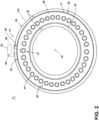
- FIG. 2 depicts a cross-sectional view of the combustion section 14 along line II-II of FIG. 1 .
- the combustion section 14 can include a combustor 30 with an annular arrangement of combustor cups 31 disposed around the centerline or rotational axis 20 of the turbine engine 10.
- the combustor 30 can have a can, can-annular, or annular arrangement depending on the type of engine in which the combustor 30 is located.
- the combustor 30 can have a combination arrangement located with a shroud or casing 29 of the engine 10.
- the shroud or casing 29 can enshroud or cover at least a portion of the combustion section 14.
- the combustor 30 can be at least partially defined by a combustor liner 40.
- the combustor liner 40 can include an outer liner 41 and an inner liner 42 concentric with respect to each other and arranged in an annular fashion about the engine centerline or rotational axis 20.
- the combustor liner 40 can have an annular structure about the combustor 30.
- the combustor liner 40 can include multiple segments or portions collectively forming the combustor liner 40.
- the combustor liner 40 can have an annular structure about the combustor 30.
- the combustor liner 40 can include multiple segments or portions collectively forming the combustor liner 40.
- the combustor liner 40 can include the outer liner 41 radially spaced from the inner liner 42.
- the combustor liner 40 can include a single liner.
- a dome assembly 44 together with the combustor liner 40 can at least partially define a combustion chamber 50 arranged annularly about the rotational axis 20.
- a dome wall 46 of the dome assembly 44 can be substantially perpendicular to the rotational axis 20 and can cooperate with the outer liner 41, the inner liner 42, or both, to at least partially define the combustion chamber 50.
- a compressed air passage 32 can be defined at least in part by both the combustor liner 40 and the casing 29.
- the combustor 30 can include or is connected to a fuel supply 34 (e.g., an external fuel manifold).
- the fuel supply 34 can be connected to an outer surface 62 of the casing 29, which can be an opposite surface from an inner surface 60.
- a fuel nozzle 38 fluidly couples the fuel supply 34 with the combustor cups 31 and the combustion chamber 50.
- the fuel F can include any suitable fuel, including hydrocarbon fuel or hydrogen fuel in non-limiting examples.
- the fuel nozzle 38 can be a hydrogen fuel nozzle and the fuel nozzle assembly 48 can be a hydrogen fuel nozzle assembly.
- the combustor cups 31 can be separately connected to the dome wall 46.
- the combustor cups 31 can be connected to the dome wall 46 in a circumferentially spaced configuration.
- the combustor cups 31 can be disposed at a radial distance from the rotational axis 20 that is greater than a radial distance of the inner liner 42 and less than a radial distance of the outer liner 41.
- FIG. 3 depicts portions of a combustion section 14 of FIG. 1 , including the fuel nozzle 38 secured to the combustion chamber 50 via a coupling 80.
- the fuel nozzle 38 can include a nozzle tube 70.
- the nozzle tube 70 can be fluidly coupled to the fuel supply 34.
- the nozzle tube 70 can provide fuel F received by the fuel nozzle 38 (e.g., from a fuel supply 34) to the combustion chamber 50.
- the nozzle tube 70 can include a nozzle tip 72 disposed at its distal end.
- the nozzle tip 72 can include one or more openings that allow fuel F to exit the fuel nozzle 38 and enter the combustion chamber 50.
- a fuel nozzle assembly 48 can include the fuel nozzle 38 and the coupling 80.
- the fuel nozzle 38 can include or be fluidly coupled with a swirler 74.
- the swirler 74 can be provided at or about the dome wall 46 and, in some instances, can extend into or through the dome wall 46.
- the swirler 74 can swirl incoming air, such as compressed air from the compressor section 12, in proximity of fuel F exiting the nozzle tip 72, which may facilitate a homogeneous mixture of air and fuel entering the combustor 30.
- the swirler 74 can be fixed (e.g., rigidly, permanently) to the dome wall 46.
- the swirler 74 can be rigidly fixed to the dome wall 46 via welding, brazing, fasteners, or a combination thereof.
- a swirler 74 can be connected to and at least partially surround the nozzle tube 70 and the nozzle tip 72.
- the nozzle tip 72 may extend into and through the swirler 74.
- the nozzle tube 70 can be rigidly fixed (e.g., bolted, brazed, welded, riveted, fastened, etc.) to the swirler 74 such that the fuel nozzle 38 is rigidly fixed to the swirler 74, the dome wall 46, or both.
- the swirler 74 may be rigidly fixed (e.g., bolted, brazed, welded, riveted, fastened, etc.) to the dome wall 46, which may provide a configuration in which the nozzle tip 72 and the swirler 74 are fixed to the dome wall 46 in a concentric arrangement, which may provide consistent flame distribution in the combustion chamber 50.
- the nozzles can move, at least to some degree, relative to the dome wall, which can provide inconsistent flame distribution.
- Some fuels such as hydrogen are particularly sensitive to interactions with oxidizers, so misalignment between two or more of the nozzle tip 72, the swirler 74, or the dome wall 46 could have significant and undesired effects on flame distribution. Fixing the nozzle tip 72, the swirler 74, and the dome wall 46 relative to each other in a proper alignment (e.g., with the nozzle tip 72 and the swirler 74 in a concentric configuration) may limit or eliminate such undesired effects on flame distribution.
- a fuel nozzle 38 may provide fuel F to a combustor cup 31 via a single hole 76 (e.g., a through passage) in the casing 29.
- Other designs include a hole for fluid flow and a plurality of additional fastener holes for each nozzle. With some aspects of the current disclosure, the number of holes 76 in the casing 29 is reduced compared to such other designs. Some other designs may also include oversized casing holes to allow for removal of a nozzle from a casing. With the instant design, the casing 29 may not include any such oversized casing holes.
- the casing hole 76 may be just large enough for the insertion and rotation of a second shaft 86 and may not be large enough for the whole fuel nozzle 38 to pass through (e.g., the flange 82 may not be capable of being passed through the casing hole 76).
- a proximal end of the nozzle tube 70 can be connected to the coupling 80, which can be connected to the casing 29, the fuel supply 34, or both.
- the nozzle tip 72 can be connected at or about a distal end of the nozzle tube 70.
- the dome wall 46 can be substantially annular and substantially perpendicular to at least some portions of the casing 29, but the dome wall 46 can include other configurations.
- the nozzle tube 70 can include a generally L-shaped configuration.
- a first section of the nozzle tube 70 may extend generally radially inward from the casing 29 and the fuel supply 34, and a second section of the nozzle tube 70 may extend generally axially from the first section toward the dome wall 46.
- the first section may be substantially perpendicular to the nozzle tip 72.
- the dome assembly 44 can include an extension 64.
- the extension 64 can extend generally axially forward from the dome wall 46 and taper radially inward and may at least partially cover and enclose the fuel nozzle 38 and the swirler 74.
- FIG. 4 depicts a cross-section of the fuel nozzle 38 connected to the casing 29 via the coupling 80.
- the coupling 80 can include a flange 82, a first shaft 84, a second shaft 86, and a nut 88.
- the flange 82 can be connected (e.g., rigidly fixed) to a proximal end of the nozzle tube 70. In an assembled configuration, the flange 82 can be adjacent to or in contact with the inner surface 60 of the casing 29.
- the first shaft 84 can be engaged with the flange 82 and extend through the casing hole 76 beyond the outer surface 62 of the casing 29 and fluidly couple the fuel nozzle 38, the coupling 80, or both to the fuel supply 34.
- the second shaft 86 can be disposed at least partially around the first shaft 84, extend through the casing hole 76, engage the flange 82, or a combination thereof.
- the nozzle tube 70 can be disposed at a first side 92 (e.g., an inner side) of the flange 82, and the nut 88 can be disposed at a second side 94 (e.g., an outer side) of the flange 82 that is opposite the first side 92.
- the nut 88 can engage the second shaft 86 and contact the outer surface 62 of the casing 29, such as to apply a clamping force to the casing 29 between the nut 88 and the flange 82 to fix the nozzle 38 with the casing 29.
- the nut 88 may be disposed opposite the flange 82 with a portion of the casing 29 therebetween.
- the first shaft 84 includes a first fluid passage 100
- the flange 82 includes a second fluid passage 102
- the nozzle tube 70 includes a third fluid passage 104.
- the first fluid passage 100 can be fluidly coupled with the fuel supply 34 and fluidly coupled with the second fluid passage 102.
- the second fluid passage 102 can be fluidly coupled with the third fluid passage 104, such as to provide fluid communication from the fuel supply 34 to the combustion chamber 50.
- FIG. 5 depicts an example of the flange 82.
- the flange 82 can include an inner portion 110 and an outer portion 112 that may be spaced (e.g., radially) from the inner portion 110 by a channel 114.
- the flange 82 can be cylindrical and the channel 114 can be annular.
- the channel 114 can include at least one threaded surface 116.
- the inner portion 110 can include an axial surface 120 that may face away from nozzle tube 70 ( FIG. 4 ), toward the casing 29 ( FIG. 4 ), or both.
- the axial surface 120 can include one or more axially-extending formations 122, such as one or more voids, one or more protrusions (e.g., teeth), or a combination thereof.
- the one or more formations 122 can be configured to engage corresponding formations 124 of a first axial surface 126 of the first shaft 84 (see, e.g., FIG. 4 ).
- the formations 124 of the first shaft 84 can include complementary voids, protrusions (e.g., teeth), or both such that when the axial surface 120 of the flange 82 is engaged with the first axial surface 126 ( FIG. 4 ) of the first shaft 84 ( FIG. 4 ), the formations 122 are engaged with the formations 124 and relative rotation between the flange 82 and the first shaft 84 is restricted or prevented.
- the flange 82 can include a first seal recess 140, a second seal recess 142, or both.
- the inner portion 110 can include the first seal recess 140.
- a first seal 144 can be disposed at least partially in the first seal recess 140, such as to provide a fluid seal between the flange 82 and the first shaft 84 ( FIG. 4 ).
- a second seal 146 can be disposed at least partially in the second seal recess 142, such as to provide a fluid seal between the flange 82 and the inner surface 60 of the casing 29 ( FIG. 4 ).
- the diameter of the first seal 144 can be smaller than the diameter of the casing hole 76, and the diameter of the second seal 146 can be larger than the diameter of the casing hole 76 (see, e.g., FIG. 4 ).
- the second seal 146 can, for example, be configured to restrict the flow of pressurized air inside the casing 29, such as in a space 202 ( FIG. 4 ), from flowing through the casing hole 76 to a space 200 ( FIG. 4 ) outside of the casing 29.
- the second seal 146 can include a C-seal.
- the second seal 146 can include a metallic seal, anon-metallic seal, or a combination of both.
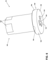
- FIGs. 6 and 7 depict an example of the first shaft 84.
- a first axial end 150 of the first shaft 84 can include the first axial surface 126, which can include the formations 124.
- the first axial end 150 can include one or more leak channels 154 formed in a second axial surface 156 of the first shaft 84 that faces away from the flange 82.
- the one or more leak channels 154 can at least partially form a leak path LP (see, e.g., FIG. 9 ) for fluid that flows out of the first fluid passage 100 or the second fluid passage 102 ( FIG. 5 ) and past the first seal 144 ( FIG. 5 ) between the axial surface 120 ( FIG. 5 ) of the flange 82 ( FIG.
- a second axial end 152 of the first shaft 84 can include one or more flat portions 158, such as for applying torque or resisting the application of torque to the first shaft 84.
- the first axial end 150 can include a radial extension 160 having a larger diameter than the other portions of the first axial end 150, the second axial end 152, or both.
- the radial extension 160 can define the second axial surface 156 and may provide the outer radial surface of the first shaft 84 with a stepped configuration.
- FIG. 8 depicts an example of the second shaft 86.
- the second shaft 86 can include a threaded surface 170, which can be disposed at an outer radial surface of the second shaft 86.
- the threaded surface 170 can engage the threaded surface 116 ( FIG. 5 ) of the flange 82 ( FIG. 5 ).
- a first axial end 172 of the second shaft 86 can be inserted at least partially into the channel 114 ( FIG. 5 ), such as when the threaded surface 170 of the second shaft 86 engages the threaded surface 116 of the flange 82 ( FIG. 5 ).
- a second axial end 174 of the second shaft 86 can include one or more flat portions 176, such as for applying torque or resisting the application of torque to the second shaft 86.
- the second shaft 86 can include an inner axial surface 180 that can include one or more leak channels 182.
- the inner axial surface 180 can face toward the flange 82.
- the one or more leak channels 182 can at least partially form a leak path LP (see, e.g., FIG. 9 ) for fluid that flows out of the first fluid passage 100 ( FIG. 4 ) or the second fluid passage 102 ( FIG. 4 ) and past the first seal 144 ( FIG. 5 ) between the axial surface 120 ( FIG. 5 ) of the flange 82 and the first axial surface 126 ( FIG.
- the leak channels 182 of the second shaft 86 can cooperate with the leak channels 154 ( FIG. 6 ) of the first shaft 84 ( FIG. 6 ). In other configurations, the leak channels 182 can function separately from and in addition to the leak channels 154 ( FIG. 6 ), or instead of the leak channels 154.
- the inner axial surface 180 of the second shaft 86 can be adjacent to, in contact with, or both, the second axial surface 156 ( FIG. 7 ) of the first shaft 84.
- the first axial end 172 of the second shaft 86 can include a larger inner diameter than the second axial end 174, which may provide an inner surface 210 (e.g., an inner radial surface) of the second shaft 86 with a stepped configuration that can correspond to the stepped configuration of the first shaft 84 ( FIG. 6 ).
- the inner axial surface 180 may extend radially between the larger inner diameter of the first axial end 172 and the smaller inner diameter of the second axial end 174.
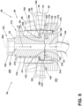
- FIG. 9 depicts an example of the coupling 80 in an assembled configuration with the casing 29.
- Assembling the fuel nozzle 38 and the coupling 80 with the casing 29 can include moving the flange 82 proximate the casing hole 76, which can include disposing the flange 82 adjacent or in contact with the inner surface 60 of the casing 29. Additionally or alternatively, moving the flange 82 proximate the casing hole 76 can include moving the second seal 146 adjacent or in contact with the inner surface 60.
- the flange 82 can be held adjacent or in contact with the inner surface 60 via a connection of the nozzle tube 70 with the dome wall 46 (see, e.g., FIGs. 3 and 4 ).
- the nozzle tube 70 can be fixed (e.g., rigidly) to the dome wall 46 ( FIG. 4 ) prior to completing assembly of the coupling 80 with the casing 29.
- the first shaft 84 can be connected to the flange 82, which can include inserting the first shaft 84 at least partially into the casing hole 76, engaging one or more formations 122 of the flange 82 with one or more formations 124 of the first shaft 84, disposing the first axial surface 126 of the first shaft 84 in contact with the axial surface 120 of the flange 82, aligning the first fluid passage 100 with the second fluid passage 102, disposing the first axial surface 126 in contact with the first seal 144, or a combination thereof.
- the second shaft 86 can be connected to the flange 82.
- Connecting the second shaft 86 to the flange 82 can include engaging the threaded surface 170 of the second shaft 86 with the threaded surface 116 of the flange 82, which can include inserting the first axial end 172 of the second shaft 86 at least partially into the channel 114 of the flange 82 (e.g., screwing the second shaft 86 into the flange 82).
- connecting the second shaft 86 to the flange 82 can clamp at least a portion of the first shaft 84 between the axial surface 120 of the flange 82 and the inner axial surface 180 of the second shaft 86. Clamping the first shaft 84 between the flange 82 and the second shaft 86 can, at least to some degree, compress or deform the first seal 144, such as to provide a fluid seal between the flange 82 and the first shaft 84.
- the first shaft 84 can be held in place, such as via applying a force or torque to the flat portions 158, while the second shaft 86 is connected to the flange 82, which can also hold the flange 82 in place, such as via engagement between the formations 122, 124.
- holding the first shaft 84 in place can prevent rotational forces applied to the second shaft 86 (e.g., via flat portions 176) from being transferred to the flange 82 or the nozzle tube 70, such as to prevent damage to or misalignment of the nozzle tube 70, the dome wall 46 ( FIG. 4 ), or both. Holding the flange 82 directly may not be feasible due to its position inside the casing 29 (e.g., insufficient room for tools, inaccessible, etc.).
- the nut 88 can be connected to the second shaft 86.
- Connecting the nut 88 to the second shaft 86 can include engaging a threaded inner surface 190 of the nut 88 with the threaded surface 170 of the second shaft 86 (e.g., the nut 88 may be screwed onto the second shaft 86).
- the flange 82 and the nut 88 can be engaged with the same threaded surface 170 of the second shaft 86.
- the nut 88 can be threaded onto the second shaft 86 until the nut 88 contacts the outer surface 62 of the casing 29, a threshold torque is reached, or both.
- Torque may be applied via one or more flat portions 192 of the nut 88.
- Connecting the nut 88 with the second shaft 86 can include compressing or deforming the second seal 146, at least to some degree, such as to provide a fluid seal between the flange 82 and the inner surface 60 of the casing 29. Additionally or alternatively, connecting the nut 88 with the second shaft 86 can clamp a portion of the casing 29 between the flange 82 and the nut 88, which may rigidly fix the nozzle 38 with the casing 29.
Landscapes
- Engineering & Computer Science (AREA)
- General Engineering & Computer Science (AREA)
- Chemical & Material Sciences (AREA)
- Combustion & Propulsion (AREA)
- Mechanical Engineering (AREA)
- Turbine Rotor Nozzle Sealing (AREA)
- Joints Allowing Movement (AREA)
Abstract
Description
- The present subject matter relates generally to a gas turbine engine having a fuel nozzle.
- Turbine engines are driven by a flow of combustion gases passing through the engine to rotate a multitude of turbine blades, which, in turn, rotate a compressor to provide compressed air to the combustor for combustion. A combustor can be provided within the turbine engine and is fluidly coupled with a turbine into which the combusted gases flow.
- Historically, hydrocarbon fuels are used in the combustor of a turbine engine. Generally, air and fuel are fed to a combustion chamber, the air and fuel are mixed, and then the fuel is burned in the presence of the air to produce hot gas. The hot gas is then fed to a turbine where it cools and expands to produce power. By-products of the fuel combustion typically include environmentally unwanted byproducts, such as nitrogen oxide and nitrogen dioxide (collectively called NOx), carbon monoxide (CO), unburned hydrocarbons (UHC) (e.g., methane and volatile organic compounds that contribute to the formation of atmospheric ozone), and other oxides, including oxides of sulfur (e.g., SO2 and SO3).
- To reduce the environmentally unwanted byproducts, other fuels, such as hydrogen, are being explored. Hydrogen or hydrogen mixed with another element has a higher flame temperature than traditional hydrocarbon fuels. That is, hydrogen or a hydrogen mixed fuel typically has a wider flammable range and a faster burning velocity than traditional hydrocarbon-based fuels.
- In the drawings:
-
FIG. 1 is a schematic cross-sectional view of a turbine engine having a compression section, a combustion section, and a turbine section in accordance with various aspects described herein. -
FIG. 2 is a schematic view of the combustion section ofFIG. 1 along line II-II in accordance with various aspects described herein. -
FIG. 3 is a schematic view illustrating portions of a fuel nozzle connected to a casing and a dome wall in accordance with various aspects described herein. -
FIG. 4 is a schematic sectional view of the fuel nozzle ofFIG. 3 . -
FIG. 5 is a perspective view of a flange of a coupling of a fuel nozzle in accordance with various aspects described herein. -
FIGs. 6 and7 are perspective views of a first shaft of a coupling of a fuel nozzle in accordance with various aspects described herein. -
FIG. 8 is a perspective view of a second shaft of a coupling of a fuel nozzle in accordance with various aspects described herein. -
FIG. 9 is an enlarged sectional view of a coupling of a fuel nozzle connected to a casing in accordance with various aspects described herein. -
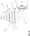
FIG. 10 is a schematic perspective view illustrating portions of a fuel nozzle connected to a casing and a dome wall in accordance with various aspects described herein. -
FIG. 11 is a schematic sectional view of the fuel nozzle ofFIG. 10 . -
FIG. 12 is a perspective view of a flange of a coupling of a fuel nozzle in accordance with various aspects described herein. -
FIG. 13 is a perspective view of a second shaft of a coupling of a fuel nozzle in accordance with various aspects described herein. -
FIG. 14 is a perspective view of a third shaft of a coupling of a fuel nozzle in accordance with various aspects described herein. -
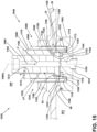
FIG. 15 is an enlarged sectional view of a coupling of a fuel nozzle connected to a casing in accordance with various aspects described herein. -
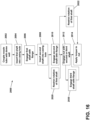
FIG. 16 is a flow diagram illustrating a method of assembling a fuel nozzle assembly in a gas turbine engine in accordance with various aspects described herein. - Aspects of the disclosure described herein are directed to a combustor. For purposes of illustration, the present disclosure will be described with respect to a turbine engine. It will be understood, however, that aspects of the disclosure described herein are not so limited and that a combustor as described herein can be implemented in engines, including but not limited to turbojet, turboprop, turboshaft, and turbofan engines. Aspects of the disclosure discussed herein may have general applicability within non-aircraft engines having a combustor, such as other mobile applications and non-mobile industrial, commercial, and residential applications.
- The word "exemplary" is used herein to mean "serving as an example, instance, or illustration." Any implementation described herein as "exemplary" is not necessarily to be construed as preferred or advantageous over other implementations. Additionally, unless specifically identified otherwise, all embodiments described herein should be considered exemplary.
- As used herein, the terms "first", "second", and "third" may be used interchangeably to distinguish one component from another and are not intended to signify location or importance of the individual components.
- The terms "forward" and "aft" refer to relative positions within a gas turbine engine or vehicle, and refer to the normal operational attitude of the gas turbine engine or vehicle. For example, with regard to a gas turbine engine, forward refers to a position closer to an engine inlet and aft refers to a position closer to an engine exhaust.
- As used herein, the term "upstream" refers to a direction that is opposite the fluid flow direction, and the term "downstream" refers to a direction that is in the same direction as the fluid flow. The term "fore" or "forward" means in front of something and "aft" or "rearward" means behind something. For example, when used in terms of fluid flow, fore/forward can mean upstream and aft/rearward can mean downstream.
- The term "fluid" may be a gas or a liquid. The term "fluid communication" means that a fluid is capable of making the connection between the areas specified.
- Additionally, as used herein, the terms "radial" or "radially" refer to a direction away from a common center. For example, in the overall context of a turbine engine, radial refers to a direction along a ray extending between a center longitudinal axis of the engine and an outer engine circumference. In the context of a coupling of a fuel nozzle, radial can refer to a direction along a ray extending between a centerline of the coupling or a shaft thereof and an outer circumference of the coupling.
- All directional references (e.g., radial, axial, proximal, distal, upper, lower, upward, downward, left, right, lateral, front, back, top, bottom, above, below, vertical, horizontal, clockwise, counterclockwise, upstream, downstream, forward, aft, etc.) are only used for identification purposes to aid the reader's understanding of the present disclosure, and do not create limitations, particularly as to the position, orientation, or use of aspects of the disclosure described herein. Connection references (e.g., attached, coupled, connected, and joined) are to be construed broadly and can include intermediate structural elements between a collection of elements and relative movement between elements unless otherwise indicated. As such, connection references do not necessarily infer that two elements are directly connected and in fixed relation to one another. The exemplary drawings are for purposes of illustration only the dimensions, positions, order, and relative sizes reflected in the drawings attached hereto can vary.
- The singular forms "a", "an", and "the" include plural references unless the context clearly dictates otherwise. Furthermore, as used herein, the term "set" or a "set" of elements can be any number of elements, including only one.
- Uses of "and" and "or" are to be construed broadly. For example and without limitation, uses of "and" do not necessarily require all elements or features listed, and uses of "or" are inclusive unless such a construction would be illogical.
- Approximating language, as used herein throughout the specification and claims, is applied to modify any quantitative representation that could permissibly vary without resulting in a change in the basic function to which it is related. Accordingly, a value modified by a term or terms, such as "about", "approximately", "generally", and "substantially", are not to be limited to the precise value specified. In at least some instances, the approximating language may correspond to the precision of an instrument for measuring the value, or the precision of the methods or machines for constructing or manufacturing the components and systems. In at least some instances, the approximating language may correspond to the precision of an instrument for measuring the value, or the precision of the methods or machines for constructing or manufacturing the components and systems. For example, the approximating language may refer to being within a 1, 2, 4, 5, 10, 15, or 20 percent margin in either individual values, range(s) of values and endpoints defining range(s) of values. Here and throughout the specification and claims, range limitations are combined and interchanged, such ranges are identified and include all the sub-ranges contained therein unless context or language indicates otherwise. For example, all ranges disclosed herein are inclusive of the endpoints, and the endpoints are independently combinable with each other.
- "Proximate" as used herein is not limiting, rather a descriptor for locating parts described herein. Further, the term "proximate" means nearer or closer to the part recited than the following part. For example, a first hole proximate a wall, the first hole located upstream from a second hole means that the first hole is closer to the wall than the first hole is to the second hole.
-
FIG. 1 is a schematic view of aturbine engine 10. As a non-limiting example, theturbine engine 10 can be used within an aircraft. Theturbine engine 10 can include, at least, acompressor section 12, acombustion section 14, and aturbine section 16. Adrive shaft 18 rotationally couples thecompressor section 12 andturbine section 16, such that rotation of one affects the rotation of the other, and defines arotational axis 20 for theturbine engine 10. - The
compressor section 12 can include a low-pressure (LP)compressor 22, and a highpressure (HP)compressor 24 serially fluidly coupled to one another. Theturbine section 16 can include anHP turbine 26, and anLP turbine 28 serially fluidly coupled to one another. Thedrive shaft 18 can operatively couple theLP compressor 22, theHP compressor 24, theHP turbine 26 and theLP turbine 28 together. Alternatively, thedrive shaft 18 can include an LP drive shaft (not illustrated) and an HP drive shaft (not illustrated). The LP drive shaft can couple theLP compressor 22 to theLP turbine 28, and the HP drive shaft can couple theHP compressor 24 to theHP turbine 26. An LP spool can be defined as the combination of theLP compressor 22, theLP turbine 28, and the LP drive shaft such that the rotation of theLP turbine 28 can apply a driving force to the LP drive shaft, which in turn can rotate theLP compressor 22. An HP spool can be defined as the combination of theHP compressor 24, theHP turbine 26, and the HP drive shaft such that the rotation of theHP turbine 26 can apply a driving force to the HP drive shaft which in turn can rotate theHP compressor 24. - The
compressor section 12 can include a plurality of axially spaced stages. Each stage includes a set of circumferentially-spaced rotating blades and a set of circumferentially-spaced stationary vanes. The compressor blades for a stage of thecompressor section 12 can be mounted to a disk, which is mounted to thedrive shaft 18. Each set of blades for a given stage can have its own disk. The vanes of thecompressor section 12 can be mounted to a casing which can extend circumferentially about and enshroud one or more sections of theturbine engine 10. It will be appreciated that the representation of thecompressor section 12 is merely schematic and that there can be any number of blades, vanes and stages. Further, it is contemplated that there can be any number of other components within thecompressor section 12. - Similar to the
compressor section 12, theturbine section 16 can include a plurality of axially spaced stages, with each stage having a set of circumferentially-spaced, rotating blades and a set of circumferentially-spaced, stationary vanes. The turbine blades for a stage of theturbine section 16 can be mounted to a disk which is mounted to thedrive shaft 18. Each set of blades for a given stage can have its own disk. The vanes of theturbine section 16 can be mounted to the casing in a circumferential manner. It is noted that there can be any number of blades, vanes and turbine stages as the illustratedturbine section 16 is merely a schematic representation. Further, it is contemplated that there can be any number of other components within theturbine section 16. - The
combustion section 14 can be provided serially between thecompressor section 12 and theturbine section 16. Thecombustion section 14 can be fluidly coupled to at least a portion of thecompressor section 12 and theturbine section 16 such that thecombustion section 14 at least partially fluidly couples thecompressor section 12 to theturbine section 16. As a non-limiting example, thecombustion section 14 can be fluidly coupled to theHP compressor 24 at an upstream end of thecombustion section 14 and to theHP turbine 26 at a downstream end of thecombustion section 14. - During operation of the
turbine engine 10, ambient or atmospheric air is drawn into thecompressor section 12 via a fan (not illustrated) upstream of thecompressor section 12, where the air is compressed defining a pressurized air. The pressurized air can then flow into thecombustion section 14 where the pressurized air is mixed with fuel and ignited, thereby generating combustion gases. Some work is extracted from these combustion gases by theHP turbine 26, which drives theHP compressor 24. The combustion gases are discharged into theLP turbine 28, which extracts additional work to drive theLP compressor 22, and the exhaust gas is ultimately discharged from theturbine engine 10 via an exhaust section (not illustrated) downstream of theturbine section 16. The driving of theLP turbine 28 drives the LP spool to rotate the fan (not illustrated) and theLP compressor 22. The pressurized airflow and the combustion gases can together define a working airflow that flows through the fan,compressor section 12,combustion section 14, andturbine section 16 of theturbine engine 10. -
FIG. 2 depicts a cross-sectional view of thecombustion section 14 along line II-II ofFIG. 1 . Thecombustion section 14 can include acombustor 30 with an annular arrangement of combustor cups 31 disposed around the centerline orrotational axis 20 of theturbine engine 10. Thecombustor 30 can have a can, can-annular, or annular arrangement depending on the type of engine in which thecombustor 30 is located. In a non-limiting example, thecombustor 30 can have a combination arrangement located with a shroud or casing 29 of theengine 10. The shroud or casing 29 can enshroud or cover at least a portion of thecombustion section 14. - The
combustor 30 can be at least partially defined by acombustor liner 40. In some examples, thecombustor liner 40 can include anouter liner 41 and aninner liner 42 concentric with respect to each other and arranged in an annular fashion about the engine centerline orrotational axis 20. In some examples, thecombustor liner 40 can have an annular structure about thecombustor 30. In some examples, thecombustor liner 40 can include multiple segments or portions collectively forming thecombustor liner 40. In some examples, thecombustor liner 40 can have an annular structure about thecombustor 30. In some examples, thecombustor liner 40 can include multiple segments or portions collectively forming thecombustor liner 40. In some examples, thecombustor liner 40 can include theouter liner 41 radially spaced from theinner liner 42. In some examples, thecombustor liner 40 can include a single liner. - A
dome assembly 44 together with thecombustor liner 40 can at least partially define acombustion chamber 50 arranged annularly about therotational axis 20. For example, adome wall 46 of thedome assembly 44 can be substantially perpendicular to therotational axis 20 and can cooperate with theouter liner 41, theinner liner 42, or both, to at least partially define thecombustion chamber 50. Acompressed air passage 32 can be defined at least in part by both thecombustor liner 40 and thecasing 29. - The
combustor 30 can include or is connected to a fuel supply 34 (e.g., an external fuel manifold). Thefuel supply 34 can be connected to anouter surface 62 of thecasing 29, which can be an opposite surface from aninner surface 60. Afuel nozzle 38 fluidly couples thefuel supply 34 with the combustor cups 31 and thecombustion chamber 50. The fuel F can include any suitable fuel, including hydrocarbon fuel or hydrogen fuel in non-limiting examples. For example, thefuel nozzle 38 can be a hydrogen fuel nozzle and thefuel nozzle assembly 48 can be a hydrogen fuel nozzle assembly. The combustor cups 31 can be separately connected to thedome wall 46. For example and without limitation, the combustor cups 31 can be connected to thedome wall 46 in a circumferentially spaced configuration. The combustor cups 31 can be disposed at a radial distance from therotational axis 20 that is greater than a radial distance of theinner liner 42 and less than a radial distance of theouter liner 41. -
FIG. 3 depicts portions of acombustion section 14 ofFIG. 1 , including thefuel nozzle 38 secured to thecombustion chamber 50 via acoupling 80. Thefuel nozzle 38 can include anozzle tube 70. Thenozzle tube 70 can be fluidly coupled to thefuel supply 34. Thenozzle tube 70 can provide fuel F received by the fuel nozzle 38 (e.g., from a fuel supply 34) to thecombustion chamber 50. Thenozzle tube 70 can include anozzle tip 72 disposed at its distal end. Thenozzle tip 72 can include one or more openings that allow fuel F to exit thefuel nozzle 38 and enter thecombustion chamber 50. Afuel nozzle assembly 48 can include thefuel nozzle 38 and thecoupling 80. - In an example aspect, the
fuel nozzle 38 can include or be fluidly coupled with aswirler 74. Theswirler 74 can be provided at or about thedome wall 46 and, in some instances, can extend into or through thedome wall 46. Theswirler 74 can swirl incoming air, such as compressed air from thecompressor section 12, in proximity of fuel F exiting thenozzle tip 72, which may facilitate a homogeneous mixture of air and fuel entering thecombustor 30. In some configurations, theswirler 74 can be fixed (e.g., rigidly, permanently) to thedome wall 46. For example, theswirler 74 can be rigidly fixed to thedome wall 46 via welding, brazing, fasteners, or a combination thereof. - In some examples, a
swirler 74 can be connected to and at least partially surround thenozzle tube 70 and thenozzle tip 72. For example, thenozzle tip 72 may extend into and through theswirler 74. With some configurations, thenozzle tube 70 can be rigidly fixed (e.g., bolted, brazed, welded, riveted, fastened, etc.) to theswirler 74 such that thefuel nozzle 38 is rigidly fixed to theswirler 74, thedome wall 46, or both. Theswirler 74 may be rigidly fixed (e.g., bolted, brazed, welded, riveted, fastened, etc.) to thedome wall 46, which may provide a configuration in which thenozzle tip 72 and theswirler 74 are fixed to thedome wall 46 in a concentric arrangement, which may provide consistent flame distribution in thecombustion chamber 50. In other designs, with floating connections between nozzles and dome walls, the nozzles can move, at least to some degree, relative to the dome wall, which can provide inconsistent flame distribution. - Some fuels, such as hydrogen, are particularly sensitive to interactions with oxidizers, so misalignment between two or more of the
nozzle tip 72, theswirler 74, or thedome wall 46 could have significant and undesired effects on flame distribution. Fixing thenozzle tip 72, theswirler 74, and thedome wall 46 relative to each other in a proper alignment (e.g., with thenozzle tip 72 and theswirler 74 in a concentric configuration) may limit or eliminate such undesired effects on flame distribution. - A
fuel nozzle 38 may provide fuel F to acombustor cup 31 via a single hole 76 (e.g., a through passage) in thecasing 29. Other designs include a hole for fluid flow and a plurality of additional fastener holes for each nozzle. With some aspects of the current disclosure, the number ofholes 76 in thecasing 29 is reduced compared to such other designs. Some other designs may also include oversized casing holes to allow for removal of a nozzle from a casing. With the instant design, thecasing 29 may not include any such oversized casing holes. For example, thecasing hole 76 may be just large enough for the insertion and rotation of asecond shaft 86 and may not be large enough for thewhole fuel nozzle 38 to pass through (e.g., theflange 82 may not be capable of being passed through the casing hole 76). - According to an aspect of the present disclosure, a proximal end of the
nozzle tube 70 can be connected to thecoupling 80, which can be connected to thecasing 29, thefuel supply 34, or both. Thenozzle tip 72 can be connected at or about a distal end of thenozzle tube 70. - In some examples, the
dome wall 46 can be substantially annular and substantially perpendicular to at least some portions of thecasing 29, but thedome wall 46 can include other configurations. Thenozzle tube 70 can include a generally L-shaped configuration. For example, a first section of thenozzle tube 70 may extend generally radially inward from thecasing 29 and thefuel supply 34, and a second section of thenozzle tube 70 may extend generally axially from the first section toward thedome wall 46. The first section may be substantially perpendicular to thenozzle tip 72. - According to an aspect of the present disclosure, the
dome assembly 44 can include anextension 64. Theextension 64 can extend generally axially forward from thedome wall 46 and taper radially inward and may at least partially cover and enclose thefuel nozzle 38 and theswirler 74. -
FIG. 4 depicts a cross-section of thefuel nozzle 38 connected to thecasing 29 via thecoupling 80. With some aspects, thecoupling 80 can include aflange 82, afirst shaft 84, asecond shaft 86, and anut 88. Theflange 82 can be connected (e.g., rigidly fixed) to a proximal end of thenozzle tube 70. In an assembled configuration, theflange 82 can be adjacent to or in contact with theinner surface 60 of thecasing 29. Thefirst shaft 84 can be engaged with theflange 82 and extend through thecasing hole 76 beyond theouter surface 62 of thecasing 29 and fluidly couple thefuel nozzle 38, thecoupling 80, or both to thefuel supply 34. Thesecond shaft 86 can be disposed at least partially around thefirst shaft 84, extend through thecasing hole 76, engage theflange 82, or a combination thereof. Thenozzle tube 70 can be disposed at a first side 92 (e.g., an inner side) of theflange 82, and thenut 88 can be disposed at a second side 94 (e.g., an outer side) of theflange 82 that is opposite thefirst side 92. Thenut 88 can engage thesecond shaft 86 and contact theouter surface 62 of thecasing 29, such as to apply a clamping force to thecasing 29 between thenut 88 and theflange 82 to fix thenozzle 38 with thecasing 29. For example, thenut 88 may be disposed opposite theflange 82 with a portion of thecasing 29 therebetween. - With some aspects, the
first shaft 84 includes afirst fluid passage 100, theflange 82 includes asecond fluid passage 102, and thenozzle tube 70 includes athird fluid passage 104. In an assembled configuration, thefirst fluid passage 100 can be fluidly coupled with thefuel supply 34 and fluidly coupled with thesecond fluid passage 102. Thesecond fluid passage 102 can be fluidly coupled with thethird fluid passage 104, such as to provide fluid communication from thefuel supply 34 to thecombustion chamber 50. -
FIG. 5 depicts an example of theflange 82. Theflange 82 can include aninner portion 110 and anouter portion 112 that may be spaced (e.g., radially) from theinner portion 110 by achannel 114. Theflange 82 can be cylindrical and thechannel 114 can be annular. Thechannel 114 can include at least one threadedsurface 116. Theinner portion 110 can include anaxial surface 120 that may face away from nozzle tube 70 (FIG. 4 ), toward the casing 29 (FIG. 4 ), or both. Theaxial surface 120 can include one or more axially-extendingformations 122, such as one or more voids, one or more protrusions (e.g., teeth), or a combination thereof. The one ormore formations 122 can be configured to engage correspondingformations 124 of a firstaxial surface 126 of the first shaft 84 (see, e.g.,FIG. 4 ). For example, theformations 124 of thefirst shaft 84 can include complementary voids, protrusions (e.g., teeth), or both such that when theaxial surface 120 of theflange 82 is engaged with the first axial surface 126 (FIG. 4 ) of the first shaft 84 (FIG. 4 ), theformations 122 are engaged with theformations 124 and relative rotation between theflange 82 and thefirst shaft 84 is restricted or prevented. - With some aspects, the
flange 82 can include afirst seal recess 140, asecond seal recess 142, or both. Theinner portion 110 can include thefirst seal recess 140. Afirst seal 144 can be disposed at least partially in thefirst seal recess 140, such as to provide a fluid seal between theflange 82 and the first shaft 84 (FIG. 4 ). Asecond seal 146 can be disposed at least partially in thesecond seal recess 142, such as to provide a fluid seal between theflange 82 and theinner surface 60 of the casing 29 (FIG. 4 ). The diameter of thefirst seal 144 can be smaller than the diameter of thecasing hole 76, and the diameter of thesecond seal 146 can be larger than the diameter of the casing hole 76 (see, e.g.,FIG. 4 ). Thesecond seal 146 can, for example, be configured to restrict the flow of pressurized air inside thecasing 29, such as in a space 202 (FIG. 4 ), from flowing through thecasing hole 76 to a space 200 (FIG. 4 ) outside of thecasing 29. In some configurations, thesecond seal 146 can include a C-seal. In some configurations, thesecond seal 146 can include a metallic seal, anon-metallic seal, or a combination of both. -
FIGs. 6 and7 depict an example of thefirst shaft 84. A firstaxial end 150 of thefirst shaft 84 can include the firstaxial surface 126, which can include theformations 124. The firstaxial end 150 can include one ormore leak channels 154 formed in a secondaxial surface 156 of thefirst shaft 84 that faces away from theflange 82. The one ormore leak channels 154 can at least partially form a leak path LP (see, e.g.,FIG. 9 ) for fluid that flows out of thefirst fluid passage 100 or the second fluid passage 102 (FIG. 5 ) and past the first seal 144 (FIG. 5 ) between the axial surface 120 (FIG. 5 ) of the flange 82 (FIG. 5 ) and the firstaxial surface 126 of thefirst shaft 84. A secondaxial end 152 of thefirst shaft 84 can include one or moreflat portions 158, such as for applying torque or resisting the application of torque to thefirst shaft 84. The firstaxial end 150 can include aradial extension 160 having a larger diameter than the other portions of the firstaxial end 150, the secondaxial end 152, or both. Theradial extension 160 can define the secondaxial surface 156 and may provide the outer radial surface of thefirst shaft 84 with a stepped configuration. -
FIG. 8 depicts an example of thesecond shaft 86. Thesecond shaft 86 can include a threadedsurface 170, which can be disposed at an outer radial surface of thesecond shaft 86. The threadedsurface 170 can engage the threaded surface 116 (FIG. 5 ) of the flange 82 (FIG. 5 ). A firstaxial end 172 of thesecond shaft 86 can be inserted at least partially into the channel 114 (FIG. 5 ), such as when the threadedsurface 170 of thesecond shaft 86 engages the threadedsurface 116 of the flange 82 (FIG. 5 ). A secondaxial end 174 of thesecond shaft 86 can include one or moreflat portions 176, such as for applying torque or resisting the application of torque to thesecond shaft 86. Thesecond shaft 86 can include an inneraxial surface 180 that can include one ormore leak channels 182. The inneraxial surface 180 can face toward theflange 82. The one ormore leak channels 182 can at least partially form a leak path LP (see, e.g.,FIG. 9 ) for fluid that flows out of the first fluid passage 100 (FIG. 4 ) or the second fluid passage 102 (FIG. 4 ) and past the first seal 144 (FIG. 5 ) between the axial surface 120 (FIG. 5 ) of theflange 82 and the first axial surface 126 (FIG. 6 ) of the first shaft 84 (FIG. 6 ). In some configurations, theleak channels 182 of thesecond shaft 86 can cooperate with the leak channels 154 (FIG. 6 ) of the first shaft 84 (FIG. 6 ). In other configurations, theleak channels 182 can function separately from and in addition to the leak channels 154 (FIG. 6 ), or instead of theleak channels 154. In an assembled configuration, the inneraxial surface 180 of thesecond shaft 86 can be adjacent to, in contact with, or both, the second axial surface 156 (FIG. 7 ) of thefirst shaft 84. The firstaxial end 172 of thesecond shaft 86 can include a larger inner diameter than the secondaxial end 174, which may provide an inner surface 210 (e.g., an inner radial surface) of thesecond shaft 86 with a stepped configuration that can correspond to the stepped configuration of the first shaft 84 (FIG. 6 ). The inneraxial surface 180 may extend radially between the larger inner diameter of the firstaxial end 172 and the smaller inner diameter of the secondaxial end 174. -
FIG. 9 depicts an example of thecoupling 80 in an assembled configuration with thecasing 29. Assembling thefuel nozzle 38 and thecoupling 80 with thecasing 29 can include moving theflange 82 proximate thecasing hole 76, which can include disposing theflange 82 adjacent or in contact with theinner surface 60 of thecasing 29. Additionally or alternatively, moving theflange 82 proximate thecasing hole 76 can include moving thesecond seal 146 adjacent or in contact with theinner surface 60. In some configurations, theflange 82 can be held adjacent or in contact with theinner surface 60 via a connection of thenozzle tube 70 with the dome wall 46 (see, e.g.,FIGs. 3 and4 ). For example, thenozzle tube 70 can be fixed (e.g., rigidly) to the dome wall 46 (FIG. 4 ) prior to completing assembly of thecoupling 80 with thecasing 29. - With some aspects, the
first shaft 84 can be connected to theflange 82, which can include inserting thefirst shaft 84 at least partially into thecasing hole 76, engaging one ormore formations 122 of theflange 82 with one ormore formations 124 of thefirst shaft 84, disposing the firstaxial surface 126 of thefirst shaft 84 in contact with theaxial surface 120 of theflange 82, aligning thefirst fluid passage 100 with thesecond fluid passage 102, disposing the firstaxial surface 126 in contact with thefirst seal 144, or a combination thereof. - In some examples, after the
first shaft 84 is connected to theflange 82, thesecond shaft 86 can be connected to theflange 82. Connecting thesecond shaft 86 to theflange 82 can include engaging the threadedsurface 170 of thesecond shaft 86 with the threadedsurface 116 of theflange 82, which can include inserting the firstaxial end 172 of thesecond shaft 86 at least partially into thechannel 114 of the flange 82 (e.g., screwing thesecond shaft 86 into the flange 82). Additionally or alternatively, connecting thesecond shaft 86 to theflange 82 can clamp at least a portion of thefirst shaft 84 between theaxial surface 120 of theflange 82 and the inneraxial surface 180 of thesecond shaft 86. Clamping thefirst shaft 84 between theflange 82 and thesecond shaft 86 can, at least to some degree, compress or deform thefirst seal 144, such as to provide a fluid seal between theflange 82 and thefirst shaft 84. With some configurations, thefirst shaft 84 can be held in place, such as via applying a force or torque to theflat portions 158, while thesecond shaft 86 is connected to theflange 82, which can also hold theflange 82 in place, such as via engagement between theformations first shaft 84 in place can prevent rotational forces applied to the second shaft 86 (e.g., via flat portions 176) from being transferred to theflange 82 or thenozzle tube 70, such as to prevent damage to or misalignment of thenozzle tube 70, the dome wall 46 (FIG. 4 ), or both. Holding theflange 82 directly may not be feasible due to its position inside the casing 29 (e.g., insufficient room for tools, inaccessible, etc.). - With some examples, after the
second shaft 86 is connected with theflange 82, thenut 88 can be connected to thesecond shaft 86. Connecting thenut 88 to thesecond shaft 86 can include engaging a threadedinner surface 190 of thenut 88 with the threadedsurface 170 of the second shaft 86 (e.g., thenut 88 may be screwed onto the second shaft 86). For example, in some instances, theflange 82 and thenut 88 can be engaged with the same threadedsurface 170 of thesecond shaft 86. Thenut 88 can be threaded onto thesecond shaft 86 until thenut 88 contacts theouter surface 62 of thecasing 29, a threshold torque is reached, or both. Torque may be applied via one or moreflat portions 192 of thenut 88. Connecting thenut 88 with thesecond shaft 86 can include compressing or deforming thesecond seal 146, at least to some degree, such as to provide a fluid seal between theflange 82 and theinner surface 60 of thecasing 29. Additionally or alternatively, connecting thenut 88 with thesecond shaft 86 can clamp a portion of thecasing 29 between theflange 82 and thenut 88, which may rigidly fix thenozzle 38 with thecasing 29. While thenut 88 is being connected to thesecond shaft 86, one or both of thefirst shaft 84 or thesecond shaft 86 may be held in place, such as via applying a force or torque to theflat portions nut 88 from being transferred to theflange 82 or thenozzle tube 70, which can help prevent damage to or misalignment of thenozzle tube 70, the dome wall 46 (FIG. 4 ), or both. Connection of thenut 88 with thesecond shaft 86 can complete connection of the coupling 80 (and the fuel nozzle assembly 48) with thecasing 29. - With some aspects, an assembled
coupling 80 can provide a leak path LP. The leak path LP can provide fluid communication from inside thecoupling 80 to thespace 200 outside of thecasing 29. For example, if a leak occurs in thecoupling 80, it may be desirable to provide leaking fluid to thespace 200 outside of thecasing 29 instead of to thespace 202 inside of thecasing 29. Theouter surface 62 of thecasing 29 may at least partially define thespace 200. Theinner surface 60 of thecasing 29 may at least partially define thespace 202. A leak may occur, in some instances, between theflange 82 and thefirst shaft 84. Such a leak could include a portion of the fluid (e.g., fuel) flowing through thefirst fluid passage 100 flowing radially outward between theaxial surfaces first seal 144 instead of flowing into thesecond fluid passage 102. The leaking fluid may then reach theinner surface 210 of thesecond shaft 86. The one ormore leak channels 154 of thefirst shaft 84, the one ormore leak channels 182 of thesecond shaft 86, or a combination thereof, can reduce the resistance to fluid flow between the first andsecond shafts space 200 outside thecasing 29. - With some examples, the first and
second shafts first shaft 84 and theinner surface 210 of thesecond shaft 86. Leaking fluid can flow through the one ormore leak channels space 200. For example, the leak path LP can include space between theaxial surfaces outer surface 214 of thefirst shaft 84 and theinner surface 210 of thesecond shaft 86 at the first axial ends 150, 172, space between the secondaxial surface 156 of thefirst shaft 84 and the inneraxial surface 180 of thesecond shaft 86, one ormore leak channels 154 of thefirst shaft 84, one ormore leak channels 182 of thesecond shaft 86, the radial gap 212, or a combination thereof. The resistance to fluid flow of the leak path LP can be lower than the resistance to fluid flow between the threadedsurfaces flange 82 and thesecond shaft 86, so most or all of the leaking fluid may flow through the leak path LP to thespace 200 outside of thecasing 29 instead of to thespace 202 inside the casing. While theleak channels shafts radial surfaces shafts leak channels - With some examples, the
first shaft 84 and thesecond shaft 86 can be cylindrical, hollow, disposed in a concentric configuration, or a combination thereof. In some examples of an assemblednozzle 38, portions of thefirst shaft 84, thesecond shaft 86, and thenut 88 can overlap in the radial direction (e.g., relative to acenterline 80a of the coupling 80). Additionally or alternatively, in some examples of an assemblednozzle 38, portions of thefirst shaft 84, thesecond shaft 86, and thecasing 29 can overlap in the radial direction. Additionally or alternatively, in some examples of an assemblednozzle 38, portions of theflange 82, thefirst seal 144, thesecond shaft 86, and thesecond seal 146 can overlap in the radial direction. The diameter of thecasing hole 76 can, in some configurations, be larger than the outer diameter of thesecond shaft 86 such that, in an assembled configuration, thesecond shaft 86 is not in contact with thecasing 29, such that thesecond shaft 86 can rotate in the casing hole 76 (e.g., when connecting to the flange 82) without contacting thecasing 29, or both. - In some examples, the
nozzle tube 70 can be fixed (e.g., brazed, welded, among others) to theflange 82 prior to connecting thenozzle tube 70 with thedome wall 46, prior to connecting thefirst shaft 84 with theflange 82, or prior to both. Additionally or alternatively, thenozzle tube 70 can be fixed (e.g., rigidly) to thedome wall 46 prior to connecting thefirst shaft 84 with theflange 82. Theflange 82, in some instances, may not extend into thecasing hole 76, such as to facilitate connection of thenozzle tube 70 with thedome wall 46, which can be generally perpendicular to thecenterline 80a of thecoupling 80. -
FIG. 10 depicts afuel nozzle assembly 1048 including afuel nozzle 1038 and acoupling 1080 connected to thecombustion chamber 50. Thefuel nozzle 1038 can include aspects similar to those of thefuel nozzle 38; therefore, like parts will be described with like numerals further increased by 1000, with it being understood that the description of the like parts of thefuel nozzle 38 can apply to thefuel nozzle 1038, except where noted. - The
fuel nozzle 1038 can include anozzle tube 1070. Thenozzle tube 1070 can be fluidly coupled to thefuel supply 34. Thenozzle tube 1070 can provide fuel F received by the fuel nozzle 1038 (e.g., from the fuel supply 34) to thecombustion chamber 50. Thenozzle tube 1070 can include anozzle tip 1072 disposed at its distal end. Thenozzle tip 1072 can include one or more openings that allow fuel F to exit thefuel nozzle 1038 and enter thecombustion chamber 50. Thefuel nozzle 1038 can include or be connected to aswirler 1074 that can be connected (e.g., rigidly fixed) to thedome wall 46. - According to an aspect of the present disclosure, a proximal end of the
nozzle tube 1070 can be connected to thecoupling 1080, which can be connected to thecasing 29, thefuel supply 34, or both. -
FIG. 11 depicts a cross-section of thefuel nozzle 1038 connected to thecasing 29 via thecoupling 1080. With some aspects, thecoupling 1080 can include aflange 1082, afirst shaft 1084, asecond shaft 1086, anut 1088, and athird shaft 1090. Theflange 1082 can be connected (e.g., rigidly fixed) to a proximal end of thenozzle tube 1070. In an assembled configuration, theflange 1082 can be adjacent to or in contact with theinner surface 60 of thecasing 29. Thefirst shaft 1084 can be engaged with theflange 1082 and can, in some configurations, include one or more portions (e.g., formations 1122) that extend through thecasing hole 76 beyond theouter surface 62 of thecasing 29. Thesecond shaft 1086 can be disposed at least partially around theflange 1082, thefirst shaft 1084, or both, extend through thecasing hole 76, engage theflange 1082, or a combination thereof. Thethird shaft 1090 can be disposed at least partially around theflange 1082, thefirst shaft 1084, thesecond shaft 1086, or a combination thereof. Thethird shaft 1090 can extend through thecasing hole 76, engage theflange 1082, or a combination thereof. Thenozzle tube 1070 can be disposed at a first side 1092 (e.g., an inner side) of theflange 1082, and thenut 1088 can be disposed at a second side 1094 (e.g., an outer side) of theflange 1082 that is opposite thefirst side 1092. Thenut 1088 can engage thethird shaft 1090 and contact theouter surface 62 of thecasing 29, such as to apply a clamping force to thecasing 29 between thenut 1088 and theflange 1082 to fix (e.g., rigidly) thefuel nozzle 1038 with thecasing 29. For example, thenut 1088 may be disposed opposite theflange 1082 with a portion of thecasing 29 therebetween. - With some aspects, the
first shaft 1084 includes afirst fluid passage 1100, theflange 1082 includes asecond fluid passage 1102, and thenozzle tube 1070 includes athird fluid passage 1104. In an assembled configuration, thefirst fluid passage 1100 can be fluidly coupled with thefuel supply 34 and fluidly coupled with thesecond fluid passage 1102. Thesecond fluid passage 1102 can be fluidly coupled with thethird fluid passage 1104, such as to provide fluid communication from thefuel supply 34 to thecombustion chamber 50. - With some aspects, the
first shaft 1084 can be configured in the same or similar manner as the first shaft 84 (see, e.g.,FIGs. 6 and7 ). For example, thefirst shaft 1084 can include a firstaxial end 1150 including a firstaxial surface 1126 havingformations 1124, a secondaxial surface 1156, one ormore leak channels 1154 formed in the secondaxial surface 1156, a secondaxial end 1152 including one or moreflat portions 1158. The firstaxial end 1150 can include aradial extension 1160 having a larger diameter than other portions of the firstaxial end 1150, the secondaxial end 1152, or both. Theradial extension 1160 can define the secondaxial surface 1156, and may provide the outer radial surface of thefirst shaft 1084 with a stepped configuration. -
FIG. 12 depicts an example of theflange 1082. Theflange 1082 can include a similar configuration as the flange 82 (FIG. 5 ) and may additionally include a second threadedsurface 1118. For example, theflange 1082 can include aninner portion 1110, anouter portion 1112, achannel 1114, a first threadedsurface 1116 provided in thechannel 1114, anaxial surface 1120 that may face away from nozzle tube 1070 (FIG. 11 ), one or more axially-extendingformations 1122, afirst seal recess 1140, asecond seal recess 1142, afirst seal 1144 that can be disposed at least partially in thefirst seal recess 1140, asecond seal 1146 that can be disposed at least partially in thesecond seal recess 1142, or a combination thereof. The second threadedsurface 1118 may face radially outward toward the first threadedsurface 1116. For example, the threadedsurface channel 1114. -
FIG. 13 depicts an example of thesecond shaft 1086. Thesecond shaft 1086 can include a threadedsurface 1170, which can be disposed at an inner radial surface of thesecond shaft 1086. The threadedsurface 1170 can engage the first threadedsurface 1116 of the flange 1082 (see, e.g.,FIG. 15 ). A firstaxial end 1172 of thesecond shaft 1086 can be inserted at least partially into thechannel 1114, such as when the threadedsurface 1170 of thesecond shaft 1086 engages the first threadedsurface 1116 of theflange 1082. A secondaxial end 1174 of thesecond shaft 1086 can include one or moreflat portions 1176, such as for applying torque or resisting the application of torque to thesecond shaft 1086. Thesecond shaft 1086 can include an inneraxial surface 1180 that can include one ormore leak channels 1182. The inneraxial surface 1180 can face toward theflange 1082. The one ormore leak channels 1182 can at least partially form a leak path LP for fluid that flows out of the first fluid passage 1100 (FIG. 11 ) or the second fluid passage 1102 (FIG. 11 ) and past the first seal 1144 (FIG. 12 ) between the axial surface 1120 (FIG. 12 ) of the flange 1082 (FIG. 12 ) and the first axial surface 1126 (FIG. 12 ) of the first shaft 1084 (see, e.g.,FIG. 15 ). In some configurations, theleak channels 1182 of thesecond shaft 1086 can cooperate with the leak channels 1154 (FIG. 11 ) of thefirst shaft 1084. In other configurations, theleak channels 1182 can function separately from and in additional to the leak channels 1154 (FIG. 11 ), or instead of theleak channels 1154. In an assembled configuration (FIG. 11 ), the inneraxial surface 1180 of thesecond shaft 1086 can be adjacent to, in contact with, or both, the secondaxial surface 1156 of thefirst shaft 1084. The firstaxial end 1172 of thesecond shaft 1086 can include a larger inner diameter than the secondaxial end 1174, which may provide aninner surface 1210 of thesecond shaft 1086 with a stepped configuration that can correspond to the stepped configuration of thefirst shaft 1084. The inneraxial surface 1180 may extend radially between the larger inner diameter of the firstaxial end 1172 and the smaller inner diameter of the secondaxial end 1174. -
FIG. 14 depicts an example of thethird shaft 1090. Thethird shaft 1090 can include a threadedsurface 1230 that can be disposed at an outer radial surface of thethird shaft 1090. The threadedsurface 1230 can extend from a firstaxial end 1232 of thethird shaft 1090 toward a secondaxial end 1234 of thethird shaft 1090. The secondaxial end 1234 can include one or moreflat portions 1236, such as for applying torque or resisting the application of torque to thethird shaft 1090. Thethird shaft 1090 can, for example, be cylindrical, hollow, or both. -
FIG. 15 depicts an example of thecoupling 1080 of thefuel nozzle 1038 in an assembled configuration with thecasing 29. Assembling thefuel nozzle 1038 and thecoupling 1080 with thecasing 29 can include moving theflange 1082 proximate thecasing hole 76, which can include disposing theflange 1082 adjacent or in contact with theinner surface 60 of thecasing 29. Additionally or alternatively, moving theflange 1082 proximate thecasing hole 76 can include moving thesecond seal 1146 adjacent or in contact with theinner surface 60. In some configurations, theflange 1082 can be held adjacent or in contact with theinner surface 60 via a connection of thenozzle tube 1070 with the dome wall 46 (FIGs. 10 and11 ). For example, thenozzle tube 1070 can be fixed to the dome wall 46 (FIGs. 10 and11 ) prior to completing assembly of thecoupling 1080 with thecasing 29, which can facilitate assembly of thecoupling 1080 with thecasing 29. - With some aspects, the
first shaft 1084 can be connected to theflange 1082, which can include inserting thefirst shaft 1084 at least partially into thecasing hole 76, engaging one ormore formations 1122 of theflange 1082 with one ormore formations 1124 of thefirst shaft 1084, disposing the firstaxial surface 1126 of thefirst shaft 1084 in contact with theaxial surface 1120 of theflange 1082, aligning thefirst fluid passage 1100 with thesecond fluid passage 1102, disposing the firstaxial surface 1126 in contact with thefirst seal 1144, or a combination thereof. - In some examples, after the
first shaft 1084 is connected to theflange 1082, thesecond shaft 1086 can be connected to theflange 1082. Connecting thesecond shaft 1086 to theflange 1082 can include engaging the threadedsurface 1170 of thesecond shaft 1086 with the threadedsurface 1116 of theflange 1082, which can include inserting the firstaxial end 1172 of thesecond shaft 1086 at least partially into thechannel 1114 of the flange 1082 (e.g., screwing thesecond shaft 86 into the flange 1082). Additionally or alternatively, connecting thesecond shaft 1086 to theflange 1082 can clamp at least a portion of thefirst shaft 1084 between theaxial surface 1120 of theflange 1082 and the inneraxial surface 1180 of thesecond shaft 1086. Clamping thefirst shaft 1084 between theflange 1082 and thesecond shaft 1086 can, at least to some degree, compress or deform thefirst seal 1144, such as to provide a fluid seal between theflange 1082 and thefirst shaft 1084. With some configurations, thefirst shaft 1084 can be held in place, such as via applying a force or torque to theflat portions 1158, while thesecond shaft 1086 is connected to theflange 1082, which can also hold theflange 1082 in place, such as via engagement between theformations first shaft 1084 in place can prevent rotational forces or torque applied to the second shaft 1086 (e.g., via flat portions 1176) from being transferred to theflange 1082 or thenozzle tube 1070, such as to prevent damage to or misalignment of thenozzle tube 1070, the dome wall 46 (FIG. 11 ), or both. - With some examples, after the
second shaft 1086 is connected with theflange 1082, thethird shaft 1090 can be connected with theflange 1082. Connecting thethird shaft 1090 with theflange 1082 can include engaging the threadedsurface 1230 of thethird shaft 1090 with the threadedsurface 1118 of theflange 1082, which can include inserting the firstaxial end 1232 of thethird shaft 1090 at least partially into thechannel 1114 of the flange 1082 (e.g., screwing thethird shaft 1090 into the flange 1082). With some configurations, thefirst shaft 1084 and thesecond shaft 1086 can be held in place, such as via applying a force or torque to theflat portions third shaft 1090 is connected to theflange 1082, which can also hold theflange 1082 in place, such as via engagement between theformations first shaft 1084 in place can prevent rotational forces or torque applied to the third shaft 1090 (e.g., via flat portions 1236) from being transferred to theflange 1082 or thenozzle tube 1070, such as to prevent damage to or misalignment of thenozzle tube 1070, the dome wall 46 (FIG. 11 ), or both. - With some examples, after the
third shaft 1090 is connected with theflange 1082, thenut 1088 can be connected to thethird shaft 1090. Connecting thenut 1088 to thethird shaft 1090 can include engaging a threadedinner surface 1190 of thenut 1088 with the threadedsurface 1230 of the third shaft 1090 (e.g., thenut 1088 may be screwed onto the third shaft 1090). Thenut 1088 can be threaded onto thethird shaft 1090 until thenut 1088 contacts theouter surface 62 of thecasing 29, a threshold torque is reached, or both. Torque may be applied to thenut 1088 via one or moreflat portions 1192 of thenut 1088. Connecting thenut 1088 with thethird shaft 1090 can include compressing or deforming thesecond seal 1146, at least to some degree, such as to provide a fluid seal between theflange 1082 and theinner surface 60 of thecasing 29. Additionally or alternatively, connecting thenut 1088 with thethird shaft 1090 can clamp a portion of thecasing 29 between theflange 1082 and thenut 1088, which may rigidly fix thenozzle 38 with thecasing 29. While thenut 1088 is being connected to thethird shaft 1090, one or a combination of thefirst shaft 1084, thesecond shaft 1086, or thethird shaft 1090 may be held in place, such as via applying a force or torque to theflat portions nut 1088 from being transferred to theflange 1082 or thenozzle tube 1070, which can help prevent damage to and misalignment of thenozzle tube 1070, the dome wall 46 (FIG. 11 ), or both. Connection of thenut 1088 with thethird shaft 1090 can complete connection of the coupling 1080 (and the fuel nozzle assembly 1048) with thecasing 29. - With some aspects, an assembled
coupling 1080 can provide a leak path LP. The leak path LP can provide fluid communication from inside thecoupling 1080 to thespace 200 outside of thecasing 29. For example, if a leak occurs in thecoupling 1080, it may be desirable to provide leaking fluid to thespace 200 outside of thecasing 29 instead of to thespace 202 inside of thecasing 29. A leak may occur, in some instances, between theflange 1082 and thefirst shaft 1084. Such a leak could include a portion of the fluid F (e.g., fuel) flowing through thefirst fluid passage 1100 flowing radially outward between theaxial surfaces first seal 1144 instead of flowing into thesecond fluid passage 1102. The leaking fluid may then reach theinner surface 1210 of thesecond shaft 1086. The one ormore leak channels 1154 of thefirst shaft 1084, the one ormore leak channels 1182 of thesecond shaft 1086, or a combination thereof, can reduce the resistance to fluid flow between the first andsecond shafts space 200 outside thecasing 29, as opposed to toward thespace 202. - With some examples, the first and
second shafts radial gap 1212 is disposed between anouter surface 1214 of thefirst shaft 1084 and theinner surface 1210 of thesecond shaft 1086. Leaking fluid can flow through the one ormore leak channels radial gap 1212 and then into thespace 200. For example, the leak path LP can include space between theaxial surfaces outer surface 1214 of thefirst shaft 1084 and theinner surface 1210 of thesecond shaft 1086 at the first axial ends 1150, 1172, space between the secondaxial surface 1156 of thefirst shaft 1084 and the inneraxial surface 1180 of thesecond shaft 1086, one ormore leak channels 1154 of thefirst shaft 1084, one ormore leak channels 1182 of thesecond shaft 1086, theradial gap 1212, or a combination thereof. The resistance to fluid flow of the leak path LP can be lower than the resistance to fluid flow between the threadedsurfaces flange 1082 and thesecond shaft 1086 and thethird shaft 1090, so most or all of the leaking fluid may flow through the leak path LP to thespace 200 outside of thecasing 29 instead of thespace 202 inside the casing. - With some examples, the
first shaft 1084 and thesecond shaft 1086 can be hollow, cylindrical, disposed in a concentric configuration, or a combination thereof. In some examples of an assembledfuel nozzle 1038, portions of thefirst shaft 1084, thesecond shaft 1086, thenut 1088, and thethird shaft 1090 can overlap in the radial direction (e.g., relative to acenterline 1080a of the coupling 1080). Additionally or alternatively, in some examples of an assembledfuel nozzle 1038, portions of thefirst shaft 1084, thesecond shaft 1086, thethird shaft 1090, and thecasing 29 can overlap in the radial direction. Additionally or alternatively, in some examples of the assembledfuel nozzle 1038, portions of theflange 1082, thefirst seal 1144, thesecond shaft 1086, thethird shaft 1090, and thesecond seal 1146 can overlap in the radial direction. The diameter of thecasing hole 76 can, in some configurations, be larger than the outer diameter of thethird shaft 1090 such that, in an assembled configuration, thethird shaft 1090 is not in contact with thecasing 29, such that thethird shaft 1090 can rotate in the casing hole 76 (e.g., when connecting to the flange 1082) without contacting thecasing 29, or both. - In some examples, the
nozzle tube 1070 can be fixed (e.g., brazed, welded, among others) to theflange 1082 prior to connecting thenozzle tube 1070 with the dome wall 46 (FIG. 2 ), prior to connecting thefirst shaft 1084 with theflange 1082, or prior to both. - Referring to
FIG. 16 , amethod 2000 of assembling afuel nozzle assembly FIGs. 2-15 , which can include afuel nozzle coupling gas turbine engine 10, which can include adome wall 46 and acasing 29, is generally illustrated. Themethod 2000 can include coupling anozzle tube first shaft hole 76 of the casing 29 (block 2004), engaging thefirst shaft flange 82, 1082 (block 2006), inserting asecond shaft hole 76 of the casing 29 (block 2008), engaging thesecond shaft flange 82, 1082 (block 2010), engaging anut second shaft nut fuel nozzle assembly method 2000 can include restricting rotation of thefirst shaft second shaft flange 82, 1082 (block 2020), and restricting rotation of thesecond shaft nut nut first shaft first shaft casing 29. Engaging thesecond shaft flange second shaft casing 29. Restricting rotation of thesecond shaft second shaft casing 29. Thenut casing 29. - Engaging the
first shaft flange tooth first shaft flange recess first shaft flange nozzle tube dome wall 46 can include rigidly fixing thenozzle tube dome wall 46 prior to engaging thenut second shaft third shaft 1090. Connecting thenozzle tube 70 to thedome wall 46 can include rigidly fixing thenozzle tube dome wall 46 prior to inserting thefirst shaft hole 76. Themethod 2000 can include engaging (e.g., threadedly engaging) thethird shaft 1090 with the flange 1082 (block 2030). Thenut 1088 can be engaged with thethird shaft 1090. Threadedly engaging thethird shaft 1090 with theflange 1082 can include deforming aseal 1146 disposed between theflange 1082 and aninner surface 60 of thecasing 29. - Connecting a
fuel nozzle fuel nozzle casing 29, and provide more uniform clamping force between thefuel nozzle casing 29. In some instances, such a configuration can provide more uniform forces to thefirst seal casing 29, such as compared to other designs that may have increased strength to withstand concentrated forces (e.g., from a plurality of separate bolts). - In some examples, in an assembled configuration,
flat portions casing 29, such as in thespace 200. Thenut casing 29. Thefirst shaft second shaft 86, 1086 (e.g., in a direction away from the casing 29) such thatflat portions second shaft third shaft 1090, thesecond shaft 1086 may extend axially beyond thethird shaft 1090 such thatflat portions 1176 are not covered by thethird shaft 1090. For example, thefirst shaft second shaft third shaft 1090. Thefirst shaft second shaft third shaft 1090 can extend axially beyond thenut flat portions - The
flange casing 29. Theshafts casing 29, partially in thehole 76 of thecasing 29, partially inside thecasing 29, or a combination thereof. - With some aspects, providing a
fuel nozzle fuel nozzle space 202 inside thecasing 29 and instead cause the leaking fluid to flow into thespace 200 outside of thecasing 29. Thespace 200 outside of thecasing 29 may be better configured to detect, mitigate, compensate for, or a combination thereof, leaking fluid, compared to thespace 202 inside thecasing 29. For example and without limitation, thespace 200 can include one or more leak detectors. - While the
first shaft first shaft first shaft - In some configurations, one or more portions of the
fuel nozzle dome wall 46, and theswirler swirler dome wall 46 and thenozzle tube nozzle tip swirler engine 10. For example, thedome wall 46 can be connected to thecombustor liner 40 and thenozzle 38 can be fixed (e.g., bolted, brazed, welded, riveted, fastened, etc.) to theinner surface 60 of thecasing 29. - The term "nozzle" has been used in various ways in the context of gas turbine engines. In the instant application, "nozzle" refers to a component having a portion for fluid coupling to a fuel supply and having at least one portion for fluidly coupling with a
combustor cup 31. A distal end of thefuel nozzle nozzle tube nozzle tip - Many other possible aspects and configurations in addition to those shown in the above figures are contemplated by the present disclosure. The aspects disclosed herein can reduce the number of casing holes 76, provide more uniform clamping force between the
fuel nozzle casing 29, fix relative positions of thefuel nozzle casing 29, and thedome wall 46, and reduce or eliminate the presence of leaking fluid inside thecasing 29. The technical effect is that the strength of thecasing 29 is increased, stress concentrators (e.g., bolts) can be eliminated, consistent flame distribution is provided, and fluid leaks from thefuel nozzle 38 inside thecasing 29 are reduced or eliminated. - Further aspects are provided by the subject matter of the following clauses:
- A gas turbine engine comprising: a combustion section enshrouded by a casing having at least one through passage, the combustion section comprising: a dome wall and a liner at least partially defining a combustion chamber; a fuel nozzle connected to the dome wall and having a nozzle tube; and a coupling securing the fuel nozzle with an inner surface of the casing and disposed at least partially in the at least one through passage; wherein the coupling includes a flange disposed at the inner surface of the casing, a first shaft engaged with the flange, and a second shaft disposed at least partially around the first shaft and engaged with the flange.
- The gas turbine engine of any preceding clause, wherein the fuel nozzle is rigidly fixed to the inner surface of the casing by the coupling and rigidly fixed to the dome wall.
- The gas turbine engine of any preceding clause, wherein the first shaft includes a first fluid passage, the flange includes a second fluid passage fluidly coupled with the first fluid passage, and the nozzle tube includes a third fluid passage fluidly coupled with the second fluid passage.
- The gas turbine engine of any preceding clause, wherein the first shaft and the second shaft extend into the through passage.
- The gas turbine engine of any preceding clause, wherein the coupling includes a nut disposed at an outer surface of the casing and engaged with the second shaft.
- The gas turbine engine of any preceding clause, wherein the flange is engaged with a threaded surface of the second shaft.
- The gas turbine engine of any preceding clause, wherein an axial surface of the first shaft includes a formation engaged with a corresponding formation of an axial surface of the flange.
- The gas turbine engine of any preceding clause, wherein the first shaft includes a first fluid passage, the flange includes a second fluid passage fluidly coupled with the first fluid passage, and the nozzle tube includes a third fluid passage fluidly coupled with the second fluid passage.
- The gas turbine engine of any preceding clause, wherein the first shaft, the second shaft, and the flange at least partially define a leak path providing fluid communication from inside the coupling to a space outside of the casing.
- The gas turbine engine of any preceding clause, wherein the leak path includes a leak channel of the first shaft, a leak channel of the second shaft, or both; and wherein the leak path includes a radial gap between the first shaft and the second shaft.
- The gas turbine engine of any preceding clause, wherein the coupling includes a first seal disposed in a first seal recess of the flange, and a second seal disposed in a second seal recess of the flange; wherein the flange includes a channel disposed radially between the first seal recess and the second seal recess; and wherein a portion of the second shaft is disposed in the channel.
- The gas turbine engine of any preceding clause, wherein the coupling includes a nut disposed at an outer surface of the casing; wherein the coupling includes a third shaft disposed at least partially around the second shaft; and wherein the third shaft is engaged with the flange and the nut.
- The gas turbine engine of any preceding clause, wherein the third shaft includes a threaded surface engaged with the flange and the nut; wherein the second shaft incudes a second shaft threaded surface engaged with the flange; and wherein portions of the second shaft and the third shaft are disposed in a channel of the flange.
- The gas turbine engine of any preceding clause, wherein the first shaft, the second shaft, the third shaft, and the nut include flat portions disposed outside of the casing.
- A fuel nozzle assembly for a gas turbine engine, the fuel nozzle assembly comprising: a first shaft including a first fluid passage; a flange connected to the first shaft and including a second fluid passage fluidly coupled with the first fluid passage; a nozzle tube connected to the flange and including a third fluid passage fluidly coupled with the second fluid passage, the nozzle tube disposed at a first side of the flange; a second shaft connected to the flange, the first shaft disposed at least partially in the second shaft; and a nut disposed at a second side of the flange, the second side opposite the first side.
- The fuel nozzle assembly of any preceding clause, wherein the flange, the first shaft, and the second shaft at least partially define a leak path.
- The fuel nozzle assembly of any preceding clause, wherein the leak path includes: a radial gap between the first shaft and the second shaft; and a leak channel in an axial surface of at least one of the first shaft or the second shaft.
- The fuel nozzle assembly of any preceding clause, wherein one of the flange or the first shaft includes an axially-extending tooth disposed a recess of the other of the flange and the first shaft.
- The fuel nozzle assembly of any preceding clause, wherein the first shaft extends axially beyond the second shaft such that flat portions of the first shaft are not covered by the second shaft.
- The fuel nozzle assembly of any preceding clause, further comprising a third shaft disposed at least partially around the second shaft; wherein the first shaft is disposed at least partially in the third shaft; and wherein the second shaft and the third shaft are threadedly engaged with the flange.
- The fuel nozzle assembly of any preceding clause, wherein the flange includes a channel having first threaded surface and a second threaded surface disposed at opposite sides of the channel; wherein the second shaft is engaged with the first threaded surface; and wherein the third shaft is engaged with the second threaded surface.
- A method of assembling a fuel nozzle assembly in a gas turbine engine including a dome wall and a casing, the fuel nozzle assembly including a flange, a first shaft, a second shaft, a nozzle tube, and a nut, the method comprising: connecting the nozzle tube to the dome wall; inserting the first shaft into a hole of the casing; engaging the first shaft with the flange; inserting the second shaft into the hole of the casing; engaging the second shaft with the flange; engaging the nut with the second shaft or a third shaft of the fuel nozzle assembly; and applying torque to the nut to secure the fuel nozzle assembly with the casing.
- The method of any preceding clause, further comprising restricting rotation of the first shaft while engaging the second shaft with the flange; and restricting rotation of the second shaft while engaging the nut, applying torque to the nut, or both.
- The method of any preceding clause, wherein restricting rotation of the first shaft includes applying a force or torque to a portion of the first shaft disposed outside of the casing;
- wherein engaging the second shaft with the flange includes applying a second force or torque to a portion of the second shaft disposed outside of the casing; wherein restricting rotation of the second shaft includes applying a third force or torque to the portion of the second shaft disposed outside of the casing; and wherein the nut is disposed outside of the casing.
- The method of any preceding clause, wherein engaging the first shaft with the flange includes inserting, in an axial direction, a tooth of one of the first shaft or the flange into a recess of the other of the first shaft or the flange.
- The method of any preceding clause, wherein connecting the nozzle tube to the dome wall includes rigidly fixing the nozzle tube to the dome wall prior to engaging the nut with the second shaft or the third shaft.
- The method of any preceding clause, wherein connecting the nozzle tube to the dome wall includes rigidly fixing the nozzle tube to the dome wall prior to inserting the first shaft into the hole.
- The method of any preceding clause, further comprising threadedly engaging the third shaft with the flange; wherein the nut is engaged with the third shaft.
- The method of any preceding clause, wherein threadedly engaging the third shaft with the flange includes deforming a seal disposed between the flange and an inner surface of the casing.
- A hydrogen fuel nozzle assembly for a gas turbine engine, the hydrogen fuel nozzle assembly comprising: a first shaft including a first fluid passage; a flange connected to the first shaft and including a second fluid passage fluidly coupled with the first fluid passage; a nozzle tube connected to the flange and including a third fluid passage fluidly coupled with the second fluid passage; a second shaft connected to the flange, the first shaft disposed at least partially in the second shaft; and a nut connected to the second shaft.
- The fuel nozzle assembly of any preceding claim, wherein the nut is disposed outside of the casing, and the flange is disposed inside the casing.
- A method of assembling the fuel nozzle assembly of any preceding clause in a gas turbine engine including a dome wall and a casing, the method comprising: connecting the nozzle tube to the dome wall; inserting the first shaft into a hole of the casing; engaging the first shaft with the flange; inserting the second shaft into the hole of the casing; engaging the second shaft with the flange; engaging the nut with the second shaft or a third shaft; and applying torque to the nut to secure the fuel nozzle assembly with the casing.
- The method of any preceding clause, further comprising restricting rotation of the first shaft while engaging the second shaft with the flange; and restricting rotation of the second shaft while engaging the nut, applying torque to the nut, or both.
- The method of any preceding clause, wherein restricting rotation of the first shaft includes applying a force or torque to a portion of the first shaft disposed outside of the casing; wherein engaging the second shaft with the flange includes applying a second force or torque to a portion of the second shaft disposed outside of the casing; wherein restricting rotation of the second shaft includes applying a third force or torque to the portion of the second shaft disposed outside of the casing; and wherein the nut is disposed outside of the casing.
- The method of any preceding clause, wherein engaging the first shaft with the flange includes inserting, in an axial direction, a tooth of one of the first shaft or the flange into a recess of the other of the first shaft or the flange.
- The method of any preceding clause, wherein connecting the nozzle tube to the dome wall includes rigidly fixing the nozzle tube to the dome wall prior to engaging the nut with the second shaft or the third shaft.
- The method of any preceding clause, wherein connecting the nozzle tube to the dome wall includes rigidly fixing the nozzle tube to the dome wall prior to inserting the first shaft into the hole.
- The method of any preceding clause, further comprising threadedly engaging the third shaft with the flange; wherein the nut is engaged with the third shaft.
- The method of any preceding clause, wherein threadedly engaging the third shaft with the flange includes deforming a seal disposed between the flange and an inner surface of the casing.
- While described with respect to a turbine engine, it should be appreciated that the combustor as described herein can be for any engine with a having a combustor. It should be appreciated that application of aspects of the disclosure discussed herein are applicable to engines with propeller sections or fan and booster sections along with turbojets and turbo engines as well.
- To the extent not already described, the different features and structures of the various embodiments can be used in combination, or in substitution with each other as desired. That one feature is not illustrated in all of the embodiments is not meant to be construed that it cannot be so illustrated but is done for brevity of description. Thus, the various features of the different embodiments can be mixed and matched as desired to form new embodiments, whether or not the new embodiments are expressly described. All combinations or permutations of features described herein are covered by this disclosure.
- This written description uses examples to describe aspects of the disclosure described herein, including the best mode, and also to enable any person skilled in the art to practice aspects of the disclosure, including making and using any devices or systems and performing any incorporated methods. The patentable scope of aspects of the disclosure is defined by the claims, and may include other examples that occur to those skilled in the art. Such other examples are intended to be within the scope of the claims if they have structural elements that do not differ from the literal language of the claims, or if they include equivalent structural elements with insubstantial differences from the literal languages of the claims.
Claims (15)
- A gas turbine engine (10) comprising:a combustion section (14) enshrouded by a casing (29) having at least one through passage (76), the combustion section (14) comprising:a dome wall (46) and a liner at least partially defining a combustion chamber (50);a fuel nozzle (38, 1038) connected to the dome wall (46) and having a nozzle tube (70, 1070); anda coupling (80, 1080) securing the fuel nozzle (38, 1038) with an inner surface (60) of the casing (29) and disposed at least partially in the at least one through passage (76);wherein the coupling (80, 1080) includes a flange (82, 1082) disposed at the inner surface (60) of the casing (29), a first shaft (84, 1084) engaged with the flange (82, 1082), and a second shaft (86, 1086) disposed at least partially around the first shaft (84, 1084) and engaged with the flange (82, 1082).
- The gas turbine engine (10) of claim 1, wherein the fuel nozzle (38, 1038) is rigidly fixed to the inner surface (60) of the casing (29) by the coupling (80, 1080) and rigidly fixed to the dome wall (46).
- The gas turbine engine (10) of any preceding claim, wherein the first shaft (84, 1084) includes a first fluid passage (100, 1100), the flange (82, 1082) includes a second fluid passage (102, 1102) fluidly coupled with the first fluid passage (100, 1100), and the nozzle tube (70, 1070) includes a third fluid passage (104, 1104) fluidly coupled with the second fluid passage (102, 1102).
- The gas turbine engine (10) of any preceding claim, wherein the first shaft (84, 1084) and the second shaft (86, 1086) extend into the through passage (76).
- The gas turbine engine (10) of any preceding claim, wherein the coupling (80, 1080) includes a nut (88, 1088) disposed at an outer surface (62) of the casing (29) and engaged with the second shaft (86, 1086).
- The gas turbine engine (10) of claim 5, wherein the flange (82, 1082) is engaged with a threaded surface (170, 1170) of the second shaft (86, 1086).
- The gas turbine engine (10) of claim 6, wherein an axial surface (120, 1120) of the first shaft (84, 1084) includes a formation engaged with and a corresponding formation of an axial surface (120, 1120) of the flange (82, 1082).
- The gas turbine engine (10) of claim 6 or 7, wherein the first shaft (84, 1084) includes a first fluid passage (100, 1100), the flange (82, 1082) includes a second fluid passage (102, 1102) fluidly coupled with the first fluid passage (100, 1100), and the nozzle tube (70, 1070) includes a third fluid passage (104, 1104) fluidly coupled with the second fluid passage (102, 1102).
- The gas turbine engine (10) of any of claims 6 to 8, wherein the first shaft (84, 1084), the second shaft (86, 1086), and the flange (82, 1082) at least partially define a leak path providing fluid communication from inside the coupling (80, 1080) to a space (200) outside of the casing (29).
- The gas turbine engine (10) of claim 9, wherein the leak path includes a leak channel (154, 1154) of the first shaft (84, 1084), a leak channel (182, 1182) of the second shaft (86, 1086), or both; and
wherein the leak path includes a radial gap (212, 1212) between the first shaft (84, 1084) and the second shaft (86, 1086). - The gas turbine engine (10) of any preceding claim, wherein the coupling (80, 1080) includes a first seal (144, 1144) disposed in a first seal recess (140, 1140) of the flange (82, 1082), and a second seal (146, 1146) disposed in a second seal recess (142, 1142) of the flange (82, 1082);wherein the flange (82, 1082) includes a channel (114, 1114) disposed radially between the first seal recess (140, 1140) and the second seal recess (142, 1142); andwherein a portion of the second shaft (86, 1086) is disposed in the channel (114, 1114).
- The gas turbine engine (10) of any preceding claim, wherein the coupling (80, 1080) includes a nut (88, 1088) disposed at an outer surface (62) of the casing (29);wherein the coupling (80, 1080) includes a third shaft (1090) disposed at least partially around the second shaft (86, 1086); andwherein the third shaft (1090) is engaged with the flange (82, 1082) and the nut (88, 1088).
- The gas turbine engine (10) of claim 12, wherein the third shaft (1090) includes a threaded surface (1230) engaged with the flange (82, 1082) and the nut (88, 1088);wherein the second shaft (86, 1086) incudes a second shaft (86, 1086) threaded surface (170, 1170) engaged with the flange (82, 1082); andwherein portions of the second shaft (86, 1086) and the third shaft (1090) are disposed in a channel (114, 1114) of the flange (82, 1082).
- The gas turbine engine (10) of claim 12 or 13, wherein the first shaft (84, 1084), the second shaft (86, 1086), the third shaft (1090), and the nut (88, 1088) include flat portions (158, 176, 192, 1158, 1176, 1192, 1236) disposed outside of the casing (29).
- The gas turbine engine (10) of claim 14, wherein the nut (88, 1088) is disposed outside of the casing (29), and the flange (82, 1082) is disposed inside the casing (29).
Applications Claiming Priority (1)
| Application Number | Priority Date | Filing Date | Title |
|---|---|---|---|
| US18/469,174 US12339003B2 (en) | 2023-09-18 | 2023-09-18 | Gas turbine engine and fuel nozzle therefor |
Publications (1)
| Publication Number | Publication Date |
|---|---|
| EP4524470A1 true EP4524470A1 (en) | 2025-03-19 |
Family
ID=91959186
Family Applications (1)
| Application Number | Title | Priority Date | Filing Date |
|---|---|---|---|
| EP24189371.8A Pending EP4524470A1 (en) | 2023-09-18 | 2024-07-18 | Gas turbine engine and fuel nozzle therefor |
Country Status (3)
| Country | Link |
|---|---|
| US (1) | US12339003B2 (en) |
| EP (1) | EP4524470A1 (en) |
| CN (1) | CN119642219A (en) |
Families Citing this family (1)
| Publication number | Priority date | Publication date | Assignee | Title |
|---|---|---|---|---|
| US12480657B1 (en) * | 2025-04-29 | 2025-11-25 | General Electric Company | Gas turbine engine and fuel nozzle therefor |
Citations (5)
| Publication number | Priority date | Publication date | Assignee | Title |
|---|---|---|---|---|
| US3516252A (en) * | 1969-02-26 | 1970-06-23 | United Aircraft Corp | Fuel manifold system |
| US5279112A (en) * | 1992-02-18 | 1994-01-18 | General Electric Company | Fuel line fitting |
| US5771696A (en) * | 1996-10-21 | 1998-06-30 | General Electric Company | Internal manifold fuel injection assembly for gas turbine |
| US20140245740A1 (en) * | 2013-03-04 | 2014-09-04 | David J. Wiebe | Combustor apparatus in a gas turbine engine |
| US20150000283A1 (en) * | 2013-06-27 | 2015-01-01 | Stephen A. Ramier | Combustor apparatus in a gas turbine engine |
Family Cites Families (14)
| Publication number | Priority date | Publication date | Assignee | Title |
|---|---|---|---|---|
| US2616258A (en) | 1946-01-09 | 1952-11-04 | Bendix Aviat Corp | Jet engine combustion apparatus, including pilot burner for ignition and vaporization of main fuel supply |
| US4466240A (en) | 1981-10-26 | 1984-08-21 | United Technologies Corporation | Fuel nozzle for gas turbine engine with external and internal removal capability |
| US4938019A (en) | 1987-10-16 | 1990-07-03 | Fuel Systems Textron Inc. | Fuel nozzle and igniter assembly |
| US5253810A (en) * | 1992-03-13 | 1993-10-19 | The United States Of America As Represented By The Secretary Of The Navy | High heat, high pressure, non-corrosive injector assembly |
| IT1256933B (en) | 1992-08-07 | 1995-12-27 | Weber Srl | ELECTROMAGNETICALLY OPERATED FUEL DOSING AND PULVERIZING VALVE. |
| US6250062B1 (en) | 1999-08-17 | 2001-06-26 | General Electric Company | Fuel nozzle centering device and method for gas turbine combustors |
| US6354085B1 (en) * | 2000-01-13 | 2002-03-12 | General Electric Company | Fuel injector with a fuel filter arrangement for a gas turbine engine |
| US7805948B2 (en) * | 2005-12-15 | 2010-10-05 | Pratt & Whitney Canada Corp. | Internally mounted device for a pressure vessel |
| EP2851600A1 (en) | 2013-09-20 | 2015-03-25 | Siemens Aktiengesellschaft | Device for connecting pipes, a high pressure fluid conduit system of a dual fuel engine, dual fuel engine and use of a tie nut |
| US9714767B2 (en) | 2014-11-26 | 2017-07-25 | General Electric Company | Premix fuel nozzle assembly |
| WO2017018992A1 (en) | 2015-07-24 | 2017-02-02 | Siemens Energy, Inc. | Dual stage multi-fuel nozzle including a flow-separating wall with a slip-fit joint background |
| US11230976B2 (en) | 2017-07-14 | 2022-01-25 | General Electric Company | Integrated fuel nozzle connection |
| US11255370B2 (en) | 2019-10-01 | 2022-02-22 | The Boeing Company | Ceramic fastener assembly for high temperatures |
| CN217526000U (en) | 2021-12-20 | 2022-10-04 | 广东卡沃罗氢科技有限公司 | Hydrogen gas nozzle with anti-backfire structure for hydrogen machine and hydrogen absorption device |
-
2023
- 2023-09-18 US US18/469,174 patent/US12339003B2/en active Active
-
2024
- 2024-07-18 EP EP24189371.8A patent/EP4524470A1/en active Pending
- 2024-09-05 CN CN202411242257.8A patent/CN119642219A/en active Pending
Patent Citations (5)
| Publication number | Priority date | Publication date | Assignee | Title |
|---|---|---|---|---|
| US3516252A (en) * | 1969-02-26 | 1970-06-23 | United Aircraft Corp | Fuel manifold system |
| US5279112A (en) * | 1992-02-18 | 1994-01-18 | General Electric Company | Fuel line fitting |
| US5771696A (en) * | 1996-10-21 | 1998-06-30 | General Electric Company | Internal manifold fuel injection assembly for gas turbine |
| US20140245740A1 (en) * | 2013-03-04 | 2014-09-04 | David J. Wiebe | Combustor apparatus in a gas turbine engine |
| US20150000283A1 (en) * | 2013-06-27 | 2015-01-01 | Stephen A. Ramier | Combustor apparatus in a gas turbine engine |
Also Published As
| Publication number | Publication date |
|---|---|
| CN119642219A (en) | 2025-03-18 |
| US12339003B2 (en) | 2025-06-24 |
| US20250093031A1 (en) | 2025-03-20 |
Similar Documents
| Publication | Publication Date | Title |
|---|---|---|
| EP2554910B1 (en) | Methods relating to integrating late lean injection into combustion turbine engines | |
| EP2554905A1 (en) | Assemblies and apparatus related to integrating late lean injection into combustion turbine engines | |
| EP2554906A2 (en) | Assemblies and apparatus related to integrating late lean injection into combustion turbine engines | |
| US10422533B2 (en) | Combustor with axially staged fuel injector assembly | |
| US10415831B2 (en) | Combustor assembly with mounted auxiliary component | |
| EP3220047A1 (en) | Gas turbine flow sleeve mounting | |
| EP3428537B1 (en) | Combustion chamber for a turbomachine with an integrated fuel nozzle connection | |
| US9423136B2 (en) | Bundled tube fuel injector aft plate retention | |
| US9500370B2 (en) | Apparatus for mixing fuel in a gas turbine nozzle | |
| EP4524470A1 (en) | Gas turbine engine and fuel nozzle therefor | |
| EP3220049A1 (en) | Gas turbine combustor having liner cooling guide vanes | |
| EP3309457B1 (en) | Combustion dynamics mitigation system | |
| US8276390B2 (en) | Method and system for providing a splitter to improve the recovery of compressor discharge casing | |
| EP4067746B1 (en) | Combustor having a wake energizer | |
| US12480657B1 (en) | Gas turbine engine and fuel nozzle therefor | |
| US11255545B1 (en) | Integrated combustion nozzle having a unified head end | |
| KR102570813B1 (en) | Fuel supply assembly and related methods | |
| US20250093032A1 (en) | Gas turbine engine and fuel nozzle therefor | |
| US10746101B2 (en) | Annular fuel manifold with a deflector | |
| US20180363909A1 (en) | Aerodynamic fastening of turbomachine fuel injectors | |
| EP2530385A2 (en) | Turbomachine combustor assembly including a liner stop | |
| US20170350321A1 (en) | Bundled Tube Fuel Nozzle Assembly with Tube Extensions |
Legal Events
| Date | Code | Title | Description |
|---|---|---|---|
| PUAI | Public reference made under article 153(3) epc to a published international application that has entered the european phase |
Free format text: ORIGINAL CODE: 0009012 |
|
| STAA | Information on the status of an ep patent application or granted ep patent |
Free format text: STATUS: THE APPLICATION HAS BEEN PUBLISHED |
|
| AK | Designated contracting states |
Kind code of ref document: A1 Designated state(s): AL AT BE BG CH CY CZ DE DK EE ES FI FR GB GR HR HU IE IS IT LI LT LU LV MC ME MK MT NL NO PL PT RO RS SE SI SK SM TR |
|
| STAA | Information on the status of an ep patent application or granted ep patent |
Free format text: STATUS: REQUEST FOR EXAMINATION WAS MADE |
|
| 17P | Request for examination filed |
Effective date: 20250912 |
|
| GRAP | Despatch of communication of intention to grant a patent |
Free format text: ORIGINAL CODE: EPIDOSNIGR1 |
|
| STAA | Information on the status of an ep patent application or granted ep patent |
Free format text: STATUS: GRANT OF PATENT IS INTENDED |
|
| INTG | Intention to grant announced |
Effective date: 20251210 |
|
| RAP3 | Party data changed (applicant data changed or rights of an application transferred) |
Owner name: GE MARMARA TECHNOLOGY CENTER MUHENDISLIKHIZMETLERI LTD Owner name: GENERAL ELECTRIC COMPANY |
|
| GRAS | Grant fee paid |
Free format text: ORIGINAL CODE: EPIDOSNIGR3 |
|
| GRAA | (expected) grant |
Free format text: ORIGINAL CODE: 0009210 |
|
| STAA | Information on the status of an ep patent application or granted ep patent |
Free format text: STATUS: THE PATENT HAS BEEN GRANTED |
|
| REG | Reference to a national code |
Ref country code: DE Ref legal event code: R081 Ref document number: 602024004672 Country of ref document: DE Owner name: GE MARMARA TECHNOLOGY CENTER MUHENDISLIK HIZME, TR Free format text: FORMER OWNERS: GE MARMARA TECHNOLOGY CENTER MUHENDISLIK HIZMETLERI LTD, GEBZE, KOCAELI, TR; GENERAL ELECTRIC COMPANY, CINCINNATI, OH, US Ref country code: DE Ref legal event code: R081 Ref document number: 602024004672 Country of ref document: DE Owner name: GENERAL ELECTRIC COMPANY, EVENDALE, US Free format text: FORMER OWNERS: GE MARMARA TECHNOLOGY CENTER MUHENDISLIK HIZMETLERI LTD, GEBZE, KOCAELI, TR; GENERAL ELECTRIC COMPANY, CINCINNATI, OH, US |