EP4524468A2 - Tile for a gas turbine engine combustor - Google Patents
Tile for a gas turbine engine combustor Download PDFInfo
- Publication number
- EP4524468A2 EP4524468A2 EP24189954.1A EP24189954A EP4524468A2 EP 4524468 A2 EP4524468 A2 EP 4524468A2 EP 24189954 A EP24189954 A EP 24189954A EP 4524468 A2 EP4524468 A2 EP 4524468A2
- Authority
- EP
- European Patent Office
- Prior art keywords
- tile
- regions
- gas turbine
- delimited
- turbine engine
- Prior art date
- Legal status (The legal status is an assumption and is not a legal conclusion. Google has not performed a legal analysis and makes no representation as to the accuracy of the status listed.)
- Pending
Links
Images


Classifications
-
- F—MECHANICAL ENGINEERING; LIGHTING; HEATING; WEAPONS; BLASTING
- F23—COMBUSTION APPARATUS; COMBUSTION PROCESSES
- F23R—GENERATING COMBUSTION PRODUCTS OF HIGH PRESSURE OR HIGH VELOCITY, e.g. GAS-TURBINE COMBUSTION CHAMBERS
- F23R3/00—Continuous combustion chambers using liquid or gaseous fuel
- F23R3/002—Wall structures
-
- F—MECHANICAL ENGINEERING; LIGHTING; HEATING; WEAPONS; BLASTING
- F02—COMBUSTION ENGINES; HOT-GAS OR COMBUSTION-PRODUCT ENGINE PLANTS
- F02C—GAS-TURBINE PLANTS; AIR INTAKES FOR JET-PROPULSION PLANTS; CONTROLLING FUEL SUPPLY IN AIR-BREATHING JET-PROPULSION PLANTS
- F02C7/00—Features, components parts, details or accessories, not provided for in, or of interest apart form groups F02C1/00 - F02C6/00; Air intakes for jet-propulsion plants
- F02C7/12—Cooling of plants
-
- F—MECHANICAL ENGINEERING; LIGHTING; HEATING; WEAPONS; BLASTING
- F23—COMBUSTION APPARATUS; COMBUSTION PROCESSES
- F23R—GENERATING COMBUSTION PRODUCTS OF HIGH PRESSURE OR HIGH VELOCITY, e.g. GAS-TURBINE COMBUSTION CHAMBERS
- F23R3/00—Continuous combustion chambers using liquid or gaseous fuel
- F23R3/005—Combined with pressure or heat exchangers
-
- F—MECHANICAL ENGINEERING; LIGHTING; HEATING; WEAPONS; BLASTING
- F23—COMBUSTION APPARATUS; COMBUSTION PROCESSES
- F23R—GENERATING COMBUSTION PRODUCTS OF HIGH PRESSURE OR HIGH VELOCITY, e.g. GAS-TURBINE COMBUSTION CHAMBERS
- F23R3/00—Continuous combustion chambers using liquid or gaseous fuel
- F23R3/007—Continuous combustion chambers using liquid or gaseous fuel constructed mainly of ceramic components
-
- F—MECHANICAL ENGINEERING; LIGHTING; HEATING; WEAPONS; BLASTING
- F23—COMBUSTION APPARATUS; COMBUSTION PROCESSES
- F23R—GENERATING COMBUSTION PRODUCTS OF HIGH PRESSURE OR HIGH VELOCITY, e.g. GAS-TURBINE COMBUSTION CHAMBERS
- F23R3/00—Continuous combustion chambers using liquid or gaseous fuel
- F23R3/02—Continuous combustion chambers using liquid or gaseous fuel characterised by the air-flow or gas-flow configuration
- F23R3/04—Air inlet arrangements
- F23R3/06—Arrangement of apertures along the flame tube
-
- F—MECHANICAL ENGINEERING; LIGHTING; HEATING; WEAPONS; BLASTING
- F23—COMBUSTION APPARATUS; COMBUSTION PROCESSES
- F23R—GENERATING COMBUSTION PRODUCTS OF HIGH PRESSURE OR HIGH VELOCITY, e.g. GAS-TURBINE COMBUSTION CHAMBERS
- F23R2900/00—Special features of, or arrangements for continuous combustion chambers; Combustion processes therefor
- F23R2900/00018—Manufacturing combustion chamber liners or subparts
-
- F—MECHANICAL ENGINEERING; LIGHTING; HEATING; WEAPONS; BLASTING
- F23—COMBUSTION APPARATUS; COMBUSTION PROCESSES
- F23R—GENERATING COMBUSTION PRODUCTS OF HIGH PRESSURE OR HIGH VELOCITY, e.g. GAS-TURBINE COMBUSTION CHAMBERS
- F23R2900/00—Special features of, or arrangements for continuous combustion chambers; Combustion processes therefor
- F23R2900/00019—Repairing or maintaining combustion chamber liners or subparts
-
- F—MECHANICAL ENGINEERING; LIGHTING; HEATING; WEAPONS; BLASTING
- F23—COMBUSTION APPARATUS; COMBUSTION PROCESSES
- F23R—GENERATING COMBUSTION PRODUCTS OF HIGH PRESSURE OR HIGH VELOCITY, e.g. GAS-TURBINE COMBUSTION CHAMBERS
- F23R2900/00—Special features of, or arrangements for continuous combustion chambers; Combustion processes therefor
- F23R2900/03041—Effusion cooled combustion chamber walls or domes
-
- F—MECHANICAL ENGINEERING; LIGHTING; HEATING; WEAPONS; BLASTING
- F23—COMBUSTION APPARATUS; COMBUSTION PROCESSES
- F23R—GENERATING COMBUSTION PRODUCTS OF HIGH PRESSURE OR HIGH VELOCITY, e.g. GAS-TURBINE COMBUSTION CHAMBERS
- F23R2900/00—Special features of, or arrangements for continuous combustion chambers; Combustion processes therefor
- F23R2900/03042—Film cooled combustion chamber walls or domes
-
- F—MECHANICAL ENGINEERING; LIGHTING; HEATING; WEAPONS; BLASTING
- F23—COMBUSTION APPARATUS; COMBUSTION PROCESSES
- F23R—GENERATING COMBUSTION PRODUCTS OF HIGH PRESSURE OR HIGH VELOCITY, e.g. GAS-TURBINE COMBUSTION CHAMBERS
- F23R2900/00—Special features of, or arrangements for continuous combustion chambers; Combustion processes therefor
- F23R2900/03043—Convection cooled combustion chamber walls with means for guiding the cooling air flow
-
- F—MECHANICAL ENGINEERING; LIGHTING; HEATING; WEAPONS; BLASTING
- F23—COMBUSTION APPARATUS; COMBUSTION PROCESSES
- F23R—GENERATING COMBUSTION PRODUCTS OF HIGH PRESSURE OR HIGH VELOCITY, e.g. GAS-TURBINE COMBUSTION CHAMBERS
- F23R2900/00—Special features of, or arrangements for continuous combustion chambers; Combustion processes therefor
- F23R2900/03045—Convection cooled combustion chamber walls provided with turbolators or means for creating turbulences to increase cooling
Definitions
- the present disclosure relates to a tile for a gas turbine engine combustor, a gas turbine engine combustor, and a method of improving the cooling performance of a gas turbine engine combustor.
- Combustor components operate at very high temperatures and their life is directly correlated to the local temperature profiles which they must endure.
- cooling methods are necessary to prevent excessive heat damage thereby prolonging the longevity of combustor components.
- cooling methods involve routing cooler air from the colder parts of the gas turbine engine into the combustor region to counter the negative effects of continuous operation at high temperatures.
- a tile for a gas turbine engine combustor comprising: a base comprising a hot-side surface, a cold-side surface, a first circumferential extremity, a second circumferential extremity and a local radial axis; a plurality of cooling channels having inlets on the cold-side surface and outlets on the hot-side surface; and one or more rail structures attached to the cold-side surface of the base, wherein the or each rail structure comprises one or more cambered sections arranged at an angle relative to the local radial axis.
- the or each rail structure comprises two edge sections located around the circumferential extremities.
- At least one of the edge sections comprises at least one perforation.
- At least one of the edge sections is a cambered section arranged at an angle relative to the local radial axis.
- the or each rail structure further comprises at least one circumferential section.
- At least one cambered section extends into the at least one circumferential section.
- the angle relative to the local radial axis ranges between +80 degrees and -80 degrees.
- the base further comprises at least one of a locating feature and a retaining feature embedded around at least one of the circumferential extremities.
- At least one stud for attaching the tile to an external component is attached to the cold-side surface.
- a gas turbine engine combustor comprising: a liner divided into a plurality of sectors and comprising an inner porous wall and an outer porous wall which extend circumferentially across the sectors, wherein the walls are connected via an inlet structure; a plurality of fuel injectors distributed circumferentially across the sectors of the liner and retained by the inlet structure of the liner; and at least one tile as previously recited.
- the or each rail structure is configured to seal the cavity between the cold-side surface and the liner wall to which the at least one tile is attached.
- the at least one tile is attached to the liner walls via at least one stud.
- the combustor comprising at least two tiles as previously recited, wherein the tiles are connected to each other through pairs of locating features and retaining features, and wherein the locating features and retaining features are embedded in the bases.
- a gas turbine engine comprising a gas turbine engine combustor of the first aspect.
- a method of improving the cooling performance of a gas turbine engine combustor of the second aspect comprising: providing a combustor comprising a liner having an inner porous wall and an outer porous wall and a plurality of porous tiles attached to the liner walls, wherein each tile comprises a base having a hot-side surface, a cold-side surface and a local radial axis; operating the combustor to generate combustion products, wherein the tiles are exposed to the combustion products; classifying regions of the tiles in accordance with their exposure to the combustion products, wherein regions with a higher level of exposure are classified as hot regions and regions with a lower level of exposure are classified as cool regions; delimiting the classified regions on the cold-side surfaces of the tiles by attaching rail structures to the cold-side surfaces and forming delimited hot regions and delimited cool regions, wherein each delimited region has a corresponding porosity; altering the porosities of the delimited regions and the porosities of the corresponding liner walls in accord
- a porosity ratio of the porosities of the delimited hot regions relative to the porosities of the corresponding liner walls is adjusted such that the pressure drop over the delimited hot regions is at least 10% of the combustor inlet pressure.
- the porosity ratio of the porosities of the delimited hot regions relative to the porosities of the corresponding liner walls is reduced by increasing the porosity of the liner walls and/or by reducing the porosity of the delimited hot regions.
- a porosity ratio of the porosities of the delimited cool regions relative to the porosities of the corresponding liner walls is increased by reducing the porosities of the liner walls or by reducing the porosities of the liner walls and increasing the porosities of the delimited cool regions.
- each porous tile has a number of cooling channels, wherein each cooling channel has a cross-section, and wherein an increase in the porosity of a delimited region is realised by an increase in the number of cooling channels and/or an increase in the cross-sections of the cooling channels in the delimited region and correspondingly, a decrease in the porosity of a delimited region is realised by a decrease in the number of cooling channels and/or a decrease in the cross-sections of the cooling channels in the delimited region.
- a method of manufacturing a gas turbine engine combustor of the second aspect comprising: providing a liner comprising an inner porous wall and an outer porous wall; connecting the inner wall and the outer wall via an inlet structure; mounting and retaining a plurality of fuel injectors in the inlet structure; and attaching at least one tile as previously recited to the liner walls.
- FIG. 1 A general arrangement of a gas turbine engine is shown in FIG. 1 .
- the engine is a gas turbine engine 100 with a principal rotational axis O-O.
- the engine 100 comprises a fan assembly 101, a bypass duct 105 and a core gas turbine.
- the core gas turbine comprises, in fluid flow series, an intermediate-pressure compressor 106, a high-pressure compressor 107, a combustor 108, a high-pressure turbine 109, an intermediate-pressure turbine 110, a low-pressure turbine 111.
- a nacelle 112 generally surrounds the engine 100 and defines both an intake 113 and an exhaust nozzle 114.
- the fan assembly 101 comprises a plurality of fan blades 104 mounted upon a hub 103, and a nosecone 102 connected with the hub 103 and configurated to rotate therewith.
- a nosecone 102 connected with the hub 103 and configurated to rotate therewith.
- the fan assembly 101 receives intake air A, rotates and generates two pressurised airflows: a bypass flow B which passes axially through the bypass duct 105, and a core flow C which enters the core gas turbine.
- the core flow C is compressed by the intermediate-pressure compressor 106 and is then directed into the high-pressure compressor 108 where further compression takes place.
- the compressed air exhausted from the high-pressure compressor 107 is directed into the combustor 108 where it is mixed with fuel and the mixture is combusted.
- the resultant hot combustion products then expand through, and thereby drive, the high-pressure turbine 109, the intermediate-pressure turbine 110, and the low-pressure turbine 111, before being exhausted via the exhaust nozzle 114 to provide a proportion of the overall thrust.
- the high-pressure turbine 109 drives the high-pressure compressor 107 via an interconnecting shaft.
- the intermediate-pressure turbine 110 drives the intermediate-pressure compressor 106 via another interconnecting shaft.
- the low-pressure turbine 111 drives the fan assembly 101 via yet another interconnecting shaft.
- the three interconnecting shafts are arranged concentrically around O-O. Those skilled in the art will recognise the engine 100 as having a direct-drive, three-shaft architecture.
- the engine 100 could alternatively be configured as a direct-drive, two-shaft architecture in which the intermediate-pressure spool is omitted.
- both the intermediate-pressure compressor 106 and the intermediate-pressure turbine 110 may be omitted.
- the fan blades 104 would provide an initial stage of compression, with the remainder of the overall pressure ratio of the engine 100 being delivered by the high-pressure compressor 107.
- Another direct-drive, two-shaft architecture may be implemented by providing a booster compressor between the fan assembly 101 and the high-pressure compressor 107, the booster compressor being driven by the low-pressure turbine 111.
- the engine 100 may be configured with a geared architecture, in which the low-pressure turbine 111 drives the fan assembly 101 via a reduction gearbox.
- the reduction gearbox may be an epicyclic gearbox of star, planetary or compound configuration.
- the reduction gearbox may be of any other suitable configuration, such as a layshaft.
- the engine 100 could be configured such that the fan assembly 101 generates a single pressurised airflow which is routed entirely into the core gas turbine.
- the bypass duct 105 may be omitted and the core gas turbine provides the entirety of the engine 100 thrust.
- the engine 100 could be configured without a nacelle 115 in order to be employed as a ductless fan aero engine or open fan aero engine, a marine gas turbine engine or land-based gas turbine engine.
- the combustor 108 is shown in perspective view in FIG. 2A and in sectional view in FIG. 2B .
- the combustor 108 comprises a liner 201, a plurality of fuel injectors 205 and a plurality of tiles 207.
- the liner 201 is divided into a plurality of sectors 206 and comprises an inner porous wall 202 and an outer porous wall 203 which extend circumferentially across the liner sectors 206.
- the fuel injectors 205 and tiles 207 are distributed circumferentially across the liner sectors 206.
- the liner 201 further comprises an inlet structure 204 which connects the inner wall 202 and outer wall 203 and retains the fuel injectors 205.
- a tile 207 is attached to either the inner wall 202 or the outer wall 203 of the liner 201. This attachment forms a cavity 208 which is represented by the volume delimited by the tile 207 and the liner wall to which it is attached.
- the combustor 108 is configured to receive the compressed air C' exhausted from the high-pressure compressor 107, mix a proportion of this airflow C'with a supply of fuel F and ignite the resulting mixture M to form combustion products.
- a proportion of airflow C' involved in the combustion process enters the liner 201 via the inlet structure 204.
- the supply of fuel F enters the liner 201 via the fuel injectors 205.
- the motion of the resulting fuel-air mixture M is a function of the fuel injector nozzle geometry and has a swirl component which leads to a non-uniform distribution of combustion products across the walls of the liner 201.
- the tiles 207 mounted on the liner walls are impacted in a non-uniform manner in accordance with their sectorial and axial combustor locations and the corresponding exposure to the combustion products.
- the remaining airflow which does not enter the inlet structure 204 is routed across the combustor for functional purposes such as cooling, combustion process enhancement or emissions mitigation. This fluid motion is realised via the pressure differential characterising the combustor 108 as a whole.
- the combustor 108 operates at a pressure drop between the combustor outlet pressure and combustor inlet pressure which ranges between 1% to 8%. However, in this specific embodiment, the pressure drop ranges between 2% to 5%.
- the combustor 108 comprises a number of sectors 406 which ranges between 10 to 30. However, in this specific embodiment, the combustor 108 comprises 20 sectors 406.
- FIG. 3 illustrates the attachment of a tile 207 to a liner wall.
- the attachment is realised in the same manner regardless of whether the liner wall is an inner wall 202 or an outer wall 203. In this specific embodiment, the attachment is realised through the means of a stud 301.
- a tile 207 may be attached to a liner wall via a plurality of studs 301.
- the tile 207 may be attached to liner walls without using any studs 301.
- Such configurations may rely instead on inter-tile connections with tiles 207 which do have studs 301.
- the studs 301 are attached to the surfaces of the tiles 207 and extend outwards such that they can be further attached to an external component.
- the stud 301 extends through a liner wall and is fastened to ensure the retainment of the tile 207 to the liner wall. Once attached, the tile 207 and the liner wall form a cavity 208. It will be appreciated that the cavity 208 between the tile 207 and the liner wall is formed regardless of the tile - liner attachment method.
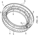
- FIG. 4 illustrates the cavity 208 delimited by the tile 207 and the liner wall to which the tile 207 is attached.
- a proportion of the airflow allocated for cooling enters the cavity 208 due to the porosity of the components delimiting the cavity 208 and interacts with the surfaces of these components.
- the distribution of cooling air within the cavity 208 serves to alter the temperature profiles in specific areas of the tile 207 such that its thermal performance and longevity are enhanced.
- FIG. 5A shows the tile 207 from the hot-side perspective.
- the tile 207 comprises a base 501 and a plurality of cooling channels 507.
- the base 501 comprises a hot-side surface 502, a cold-side surface 503, a first circumferential extremity 504, a second circumferential extremity 505 and a local radial axis 506.
- the cooling channels 507 have inlets on the cold-side surface 503 and outlets on the hot-side surface 502, thereby traversing the base 501 across its entire thickness. It will be appreciated by those skilled in the art that cooling channels are also commonly referred to as cooling holes.
- the local radial axis 506 associated with a particular location on the base 501 is taken to mean the instantaneous radial axis derived from the curvature of the base 501 at that particular location. Accordingly, depending on the overall curvature of the base 501, different locations on the base 501 may be associated with different local radial axes 506. In such a case, each location on the base 501 has a corresponding radial axis 506.
- the cooling channels 507 have curved-shaped cross-sections which remain constant as they traverse the base 501.
- the cross-sectional profile of the cooling channels 507 may be polygonal or a combination of curved and linear elements.
- the cross-sectional profile of the cooling channels 507 may exhibit an amount of tapering between the cold-side cooling channel inlet and the hot-side cooling channel outlet.
- the centrelines of the cooling channels 507 are orientated at angles ranging between -80 degrees to +80 degrees relative to an axis perpendicular to the base 501. In this specific embodiment, the cooling channel centreline angles vary between -45 degrees to +45 degrees.
- the distribution of cooling channels 507 corresponds to a tile 207 mounted on the outer wall 203 of the combustor liner 201.
- the functional requirements of the tiles 207 are derived from the sectoral and axial locations of the tiles 207 within the combustor 108, the lifecycle requirements of the tiles 207 and liner 201 and the porosity requirements of the combustor 108.
- the tile 207 further comprises four mixing ports 508 configured to enhance the combustion process by transferring a proportion of the airflow C' into the combustion zone.
- Each mixing port 508 has an inlet on the cold-side surface 503 of the base 501 and an outlet on the hot-side surface 502 of the base 501.
- the tile 207 may contain no mixing ports 208, a single mixing port 208 or a plurality of mixing ports 208.
- the base 501 of the tile 207 further comprises pairs of locating features 509 and retaining features 510 configured to enable inter-tile connections between adjacent tiles 207.
- the pairs are embedded around the circumferential extremities of the base 501 and extend outwards in the circumferential direction.
- the retaining feature 510 can be formed as a slot or as a groove on the cold-side surface 503 around a circumferential extremity of the base 501.
- the locating feature 509 may be a pin or a rod attached to the cold-side surface 503 around a circumferential extremity of the base 501.
- the pin or rod style locating feature 509 is configured to slide into the retaining feature 510 and thereby connecting two adjacent tiles 207.
- the base 501 may embed these pairs around only one of its circumferential extremities. Similarly, it will also be appreciated that these pairs may be completely omitted from the base 501 and the tile 207 as a whole. Moreover, the distribution and configuration of the pairs is shown by example only. Those skilled in the art will be familiar with various other possible arrangements for creating a joint connection between two components via a male-female system.
- the tile 207 comprises one or more rail structures attached to the cold-side surface 503 of the base 501.
- the tile 207 is shown from the cold-side perspective.
- the tile 207 comprises one rail structure 511.
- the tile 207 may comprise a plurality of rail structures 511, wherein each rail structure 511 may be connected to or separated from other rail structures 511.
- the rail structure 511 delimits a perimeter alongside the edges of the base 501 and thereby forms an internal zone on the cold-side surface 503.
- four mixing port inlets 508 are also present on the cold-side surface 503 and each of them is delimited by a circumferential section 512 contained within the rail structure 511.
- a different number of mixing ports 508 is present, then a corresponding number of associated circumferential sections 512 will be contained within the rail structure 511.
- the rail structure 511 is continuous. However, it will be appreciated that the rail structure 511 can be split continuously or non-continuously into a plurality of sections to accommodate the installation of the tile 207 onto an external component such as the liner 201 of a combustor 108 for a gas turbine engine 100. Additionally, it will also be appreciated that the rail structure 511 may contain at least one gap configured to enable the tile 207 to achieve specific pressure drop distributions.
- the perimeter delimited by the rail structure 511 comprises two edge sections 513 located around the circumferential extremities of the base 501.
- both edge sections 513 comprise a plurality of perforations 514 configured to purge the tile - liner cavity 208 when the combustor 108 is in operation.
- perforations 514 it will be appreciated that only one or none of the edge sections 513 may contain perforations 514. It will also be appreciated that either of the edge sections 513 may contain only a single perforation 514.
- the rail structure 511 is configured to seal the cavity 208 represented by the volume formed between the cold-side surface 503 of the tile 207 and the wall of the liner 201 to which the tile 207 is attached. This allows for a local pressure drop profile to be configured across the internal zone defined by the rail structure 511. The local pressure drop profile is selected as to enable the cooling air entering the cavity 208 to form an effective cooling film along the hot-side surface 502 of the tile 207.
- FIG. 6 shows an example of the rail structure 511 on the cold-side surface 503 of FIG. 5B .
- three angled cambered sections 601 and four circumferential sections 512 are presented as being contained within the rail structure 511.
- Each cambered section 601 is arranged at an angle 602, ⁇ , relative to the local radial axis 506 of the base 501.
- the angles 602 are selected such that the cambered sections 601 are parallel with each other.
- each cambered section 601 may be arranged independently of other cambered sections 601 at angles 602 which range between +80 degrees and -80 degrees.
- this configuration may involve only one cambered section 601 or a plurality of cambered sections 601 and any number of circumferential sections 512. Additionally, it will be further appreciated that at least one of the edge sections 513 of the rail structure 511 can be an angled cambered section 601.
- the cambered sections 601 serve to divide the internal zone defined by the rail structure 511 into further zones, each zone having a different local pressure drop profile. This enables a high degree of customisation for each individual zone in order to enhance the management of the cooling air budget and improve the film cooling effectiveness.
- FIG. 7 illustrates a further example of the rail structure 511 on the cold-side surface 503 of FIG. 5B .
- the rail structure 511 comprises four angled cambered sections 601 and four circumferential 512 sections.
- this configuration may involve one circumferential section 512 or a plurality of circumferential sections 512 and one cambered section 601 or a plurality of cambered sections 601.
- Each cambered section 601 may be arranged in relation to or independently of other cambered sections 601 at angles 602 which range between +80 degrees and -80 degrees.
- a cambered section 601 may be extending directly into a circumferential section 512 and vice versa.
- a cambered section 601 may be merely connected to a circumferential section 512 and vice versa only via the overall rail structure 511. Additionally, it will be further appreciated that at least one of the edge sections 513 of the rail structure 511 can be an angled cambered section 601.
- cambered sections 601 and circumferential sections 512 serve to divide the internal zone defined by the rail structure 511 into further zones, each zone having a different local pressure drop profile. This provides further customisation options for each individual zone in order to enhance the management of the cooling air budget and improve the film cooling effectiveness.
- three adjacent tiles 207 are shown connected to each other via pairs of locating features 509 and retaining features 510.
- three tiles 207 of varying circumferential dimensions and configurations are interconnected.
- the inter-tile connection system is applicable to any number of tiles 207 of any circumferential dimension and any configuration.
- any number of locating-retaining pairs may be involved in the inter-tile connection system.
- not all tiles 207 may have such pairs.
- FIG. 9A shows the regions 900 forming on the hot-side surface 502 of FIG. 5A during the operation of a tile 207 in a combustor 108 for a gas turbine 100.
- the hot-side surface 502 of a tile 207 is exposed to the combustion products.
- different regions 900 of the tile 207 experience different levels of exposure to the combustion products. Therefore, regions 900 with a higher degree of exposure to the combustion products are classified as hot regions 901 while regions 900 with a lower degree of exposure to the combustion products are classified as cool regions 902. This classification may be conducted operationally, experimentally, computationally or analytically.
- thermal paint can be applied to the hot-side surfaces 502 of the tiles 207 such that the classification of the regions 900 is determined during combustor rig testing or full gas turbine engine testing.
- the distribution of hot regions 901 and cool regions 902 is by way of example only. It will be appreciated that the exact distribution of hot 901 and cool 902 regions varies from tile 207 to tile 207 in accordance with the tile's sectorial and axial combustor location and the corresponding exposure to the combustion products.
- FIG. 9B shows the hot regions 903 and cool regions 904 on the cold-side surface 503 corresponding to the hot regions 901 and cool regions 902 of FIG. 9A .
- the cold-side surface hot 903 and cool 904 regions are delimited via the rail structure 511 of the tile 207.
- the arrangement of the rail structure 511 is by way of example only. It will be appreciated that any configuration involving at least one of a circumferential section 512 and an angled cambered segment 601 can be employed to delimit the cold-side surface hot 903 and cool 904 regions.
- the delimited cold-side surface hot 903 and cool 904 regions serve to divide the internal zone defined by the rail structure 511 into further zones, each zone having a different local pressure drop profile.
- This allows for specific cooling configurations to be implemented in accordance with the hot or cool classification of the delimited region.
- Such specific cooling configurations are achieved by altering the porosities of the delimited cold-side surface hot 903 and cool 904 regions and the porosities of the corresponding liner wall to which the tile 207 is attached.
- the implemented configurations serve to enhance the management of the cooling air budget and improve the film cooling effectiveness.
- An increase in the porosity of a delimited region is realised by an increase in the number of cooling channels 507 or an increase in the diameter of the existing cooling channels 507 in the delimited region.
- an increase in the porosity of a delimited region is realised by an increase in the number of cooling channels 507 and an increase in the diameter of the existing cooling channels 507 in the delimited region.
- a decrease in the porosity of a delimited region is realised by a decrease in the number of cooling channels 507 or a decrease in the diameter of the existing cooling channels 507 in the delimited region.
- a decrease in the porosity of a delimited region is realised by a decrease in the number of cooling channels 507 and a decrease in the diameter of the existing cooling channels 507 in the delimited region.
- the porosity ratio of the delimited cold-side surface hot regions 903 relative to the corresponding liner walls which the tile 207 is attached to is adjusted such that the pressure drop over the delimited hot regions 903 does not fall below a critical percentage value higher or equal to 10% of the combustor inlet pressure.
- This porosity ratio may be reduced by increasing the porosity of the corresponding liner walls or by reducing the porosity of the delimited hot regions 903.
- the porosity ratio may be reduced by increasing the porosity of the corresponding liner walls and by reducing the porosity of the delimited hot regions 903.
- the porosity ratio of the delimited cold-side surface cool regions 904 relative to the corresponding liner walls which the tile 207 is attached to is increased either by reducing the porosity of the liner walls or by reducing the porosity of the liner walls and increasing the porosity of the delimited cool regions 904.
- this porosity ratio is adjusted such that the pressure drop over the delimited cool regions 904 falls to zero for configurations in which cooling channels 507 having cross-sectional profiles at the manufacturing upper tolerance limit are matched with liner wall porosities having cross-sectional profiles at the manufacturing lower tolerance limit.
- the porosity of the liner walls corresponding to a delimited cold-side surface cool region 904 is equal or lower than the porosity of the liner walls corresponding to a delimited cold-side surface hot region 903.
- the effective flow area of the cooling channels 507 in the delimited cold-side surface cool regions 904 is equal or greater than the effective flow area of the cooling channels 507 in the delimited cold-side hot regions 903.
- the effective flow area of the cooling channels 507 is determined by the number of cooling channels 507 and their associated cross-sectional profiles. In this specific embodiment, the number of cooling channels 507 in the delimited cold-side surface cool regions 904 is equal or greater than the number of cooling channels 507 in the delimited cold-side hot regions 903.
- configuring the effective flow area of the cooling channels 507 may involve either changing the number of cooling channels 507 or modifying the cross-sectional profile of the cooling channels 507. Alternatively, those skilled in the art will further appreciate that configuring the effective flow area of the cooling channels 507 may involve both changing the number of cooling channels 507 and modifying the cross-sectional profile of the cooling channels 507.
Landscapes
- Engineering & Computer Science (AREA)
- Chemical & Material Sciences (AREA)
- Combustion & Propulsion (AREA)
- Mechanical Engineering (AREA)
- General Engineering & Computer Science (AREA)
- Ceramic Engineering (AREA)
- Turbine Rotor Nozzle Sealing (AREA)
Abstract
Description
- The present disclosure relates to a tile for a gas turbine engine combustor, a gas turbine engine combustor, and a method of improving the cooling performance of a gas turbine engine combustor.
- Combustor components operate at very high temperatures and their life is directly correlated to the local temperature profiles which they must endure. In the case of gas turbine engines, cooling methods are necessary to prevent excessive heat damage thereby prolonging the longevity of combustor components. Typically, cooling methods involve routing cooler air from the colder parts of the gas turbine engine into the combustor region to counter the negative effects of continuous operation at high temperatures.
- However, routing air from the colder parts of the gas turbine engine negatively impacts the engine's efficiency and environmental performance. Gas turbine manufacturers continuously attempt to find a balance between achieving an economically viable amount of life for combustor components and attaining a suitable engine efficiency whilst meeting stringent emissions regulations. Therefore, the management of the cooling air budget for combustors represents a key area of focus with critical implications for the holistic performance of gas turbine engines.
- In a first aspect, there is provided a tile for a gas turbine engine combustor, the tile comprising: a base comprising a hot-side surface, a cold-side surface, a first circumferential extremity, a second circumferential extremity and a local radial axis; a plurality of cooling channels having inlets on the cold-side surface and outlets on the hot-side surface; and one or more rail structures attached to the cold-side surface of the base, wherein the or each rail structure comprises one or more cambered sections arranged at an angle relative to the local radial axis.
- In some embodiments, the or each rail structure comprises two edge sections located around the circumferential extremities.
- In some embodiments, at least one of the edge sections comprises at least one perforation.
- In some embodiments, at least one of the edge sections is a cambered section arranged at an angle relative to the local radial axis.
- In some embodiments, the or each rail structure further comprises at least one circumferential section.
- In some embodiments, at least one cambered section extends into the at least one circumferential section.
- In some embodiments, the angle relative to the local radial axis ranges between +80 degrees and -80 degrees.
- In some embodiments, the base further comprises at least one of a locating feature and a retaining feature embedded around at least one of the circumferential extremities.
- In some embodiments, at least one stud for attaching the tile to an external component is attached to the cold-side surface.
- In another aspect, there is provided a gas turbine engine combustor, the gas turbine engine combustor comprising: a liner divided into a plurality of sectors and comprising an inner porous wall and an outer porous wall which extend circumferentially across the sectors, wherein the walls are connected via an inlet structure; a plurality of fuel injectors distributed circumferentially across the sectors of the liner and retained by the inlet structure of the liner; and at least one tile as previously recited.
- In some embodiments, the or each rail structure is configured to seal the cavity between the cold-side surface and the liner wall to which the at least one tile is attached.
- In some embodiments, the at least one tile is attached to the liner walls via at least one stud.
- In some embodiments, the combustor comprising at least two tiles as previously recited, wherein the tiles are connected to each other through pairs of locating features and retaining features, and wherein the locating features and retaining features are embedded in the bases.
- In second aspect, there is provided a gas turbine engine comprising a gas turbine engine combustor of the first aspect.
- In third aspect, there is a method of improving the cooling performance of a gas turbine engine combustor of the second aspect, the method comprising: providing a combustor comprising a liner having an inner porous wall and an outer porous wall and a plurality of porous tiles attached to the liner walls, wherein each tile comprises a base having a hot-side surface, a cold-side surface and a local radial axis; operating the combustor to generate combustion products, wherein the tiles are exposed to the combustion products; classifying regions of the tiles in accordance with their exposure to the combustion products, wherein regions with a higher level of exposure are classified as hot regions and regions with a lower level of exposure are classified as cool regions; delimiting the classified regions on the cold-side surfaces of the tiles by attaching rail structures to the cold-side surfaces and forming delimited hot regions and delimited cool regions, wherein each delimited region has a corresponding porosity; altering the porosities of the delimited regions and the porosities of the corresponding liner walls in accordance with the classifications of the delimited regions; and installing the altered tiles and liner walls in the combustor.
- In some embodiments, a porosity ratio of the porosities of the delimited hot regions relative to the porosities of the corresponding liner walls is adjusted such that the pressure drop over the delimited hot regions is at least 10% of the combustor inlet pressure.
- In some embodiments, the porosity ratio of the porosities of the delimited hot regions relative to the porosities of the corresponding liner walls is reduced by increasing the porosity of the liner walls and/or by reducing the porosity of the delimited hot regions.
- In some embodiments, a porosity ratio of the porosities of the delimited cool regions relative to the porosities of the corresponding liner walls is increased by reducing the porosities of the liner walls or by reducing the porosities of the liner walls and increasing the porosities of the delimited cool regions.
- In some embodiments, each porous tile has a number of cooling channels, wherein each cooling channel has a cross-section, and wherein an increase in the porosity of a delimited region is realised by an increase in the number of cooling channels and/or an increase in the cross-sections of the cooling channels in the delimited region and correspondingly, a decrease in the porosity of a delimited region is realised by a decrease in the number of cooling channels and/or a decrease in the cross-sections of the cooling channels in the delimited region.
- In another aspect, there is provided a method of manufacturing a gas turbine engine combustor of the second aspect, the method comprising: providing a liner comprising an inner porous wall and an outer porous wall; connecting the inner wall and the outer wall via an inlet structure; mounting and retaining a plurality of fuel injectors in the inlet structure; and attaching at least one tile as previously recited to the liner walls.
- Embodiments will now be described by way of example only, with reference to the accompanying drawings, which are purely schematic and not to scale, and in which:
-
FIG. 1 shows a gas turbine engine that has a combustor; -
FIG. 2A is a perspective view of the combustor; -
FIG. 2B is a sectional view of the combustor that has a combustor liner; -
FIG. 3 is a sectional view of a tile of the present disclosure that is attached to a wall of the combustor liner; -
FIG. 4 is a perspective view of the part of the tile that shows a cavity formed between the tile and the combustor liner; -
FIG. 5A is a view of the hot-side surface of the tile ofFIG. 3 ; -
FIG. 5B is a view of the cold-side surface of the tile ofFIG. 3 ; -
FIG. 6 shows a rail structure configuration on the cold-side surface of the tile; -
FIG. 7 shows a further rail structure configuration on the cold-side surface of the tile; -
FIG. 8 is a view of the inter-tile attachment system; -
FIG. 9A is a view of the hot and cool regions forming on the hot-side surface of a tile; and -
FIG. 9B is a view of the hot and cool regions on the cold-side surface of a tile corresponding to the hot and cool regions ofFIG. 9A . - A general arrangement of a gas turbine engine is shown in
FIG. 1 . In this embodiment, the engine is agas turbine engine 100 with a principal rotational axis O-O. Theengine 100 comprises afan assembly 101, abypass duct 105 and a core gas turbine. The core gas turbine comprises, in fluid flow series, an intermediate-pressure compressor 106, a high-pressure compressor 107, acombustor 108, a high-pressure turbine 109, an intermediate-pressure turbine 110, a low-pressure turbine 111. Anacelle 112 generally surrounds theengine 100 and defines both anintake 113 and anexhaust nozzle 114. - The
fan assembly 101 comprises a plurality offan blades 104 mounted upon ahub 103, and anosecone 102 connected with thehub 103 and configurated to rotate therewith. Those skilled in the art will be familiar with the various possible arrangements for mounting fan blades and nosecones to fan hubs, along with any other aerodynamic fairings required to seal the inner gas-washed surface of the fan stage. - In operation, the
fan assembly 101 receives intake air A, rotates and generates two pressurised airflows: a bypass flow B which passes axially through thebypass duct 105, and a core flow C which enters the core gas turbine. The core flow C is compressed by the intermediate-pressure compressor 106 and is then directed into the high-pressure compressor 108 where further compression takes place. The compressed air exhausted from the high-pressure compressor 107 is directed into thecombustor 108 where it is mixed with fuel and the mixture is combusted. The resultant hot combustion products then expand through, and thereby drive, the high-pressure turbine 109, the intermediate-pressure turbine 110, and the low-pressure turbine 111, before being exhausted via theexhaust nozzle 114 to provide a proportion of the overall thrust. - The high-
pressure turbine 109 drives the high-pressure compressor 107 via an interconnecting shaft. The intermediate-pressure turbine 110 drives the intermediate-pressure compressor 106 via another interconnecting shaft. The low-pressure turbine 111 drives thefan assembly 101 via yet another interconnecting shaft. The three interconnecting shafts are arranged concentrically around O-O. Those skilled in the art will recognise theengine 100 as having a direct-drive, three-shaft architecture. - It will be appreciated that in other embodiments, the
engine 100 could alternatively be configured as a direct-drive, two-shaft architecture in which the intermediate-pressure spool is omitted. In one such configuration, both the intermediate-pressure compressor 106 and the intermediate-pressure turbine 110 may be omitted. In operation, thefan blades 104 would provide an initial stage of compression, with the remainder of the overall pressure ratio of theengine 100 being delivered by the high-pressure compressor 107. Another direct-drive, two-shaft architecture may be implemented by providing a booster compressor between thefan assembly 101 and the high-pressure compressor 107, the booster compressor being driven by the low-pressure turbine 111. - In other embodiments, the
engine 100 may be configured with a geared architecture, in which the low-pressure turbine 111 drives thefan assembly 101 via a reduction gearbox. The reduction gearbox may be an epicyclic gearbox of star, planetary or compound configuration. Alternatively, the reduction gearbox may be of any other suitable configuration, such as a layshaft. - It will be appreciated that in other embodiments, the
engine 100 could be configured such that thefan assembly 101 generates a single pressurised airflow which is routed entirely into the core gas turbine. In this configuration, thebypass duct 105 may be omitted and the core gas turbine provides the entirety of theengine 100 thrust. - In other embodiments, the
engine 100 could be configured without a nacelle 115 in order to be employed as a ductless fan aero engine or open fan aero engine, a marine gas turbine engine or land-based gas turbine engine. - Referring again to the drawings, the
combustor 108 is shown in perspective view inFIG. 2A and in sectional view inFIG. 2B . Thecombustor 108 comprises aliner 201, a plurality offuel injectors 205 and a plurality oftiles 207. Theliner 201 is divided into a plurality ofsectors 206 and comprises an innerporous wall 202 and an outerporous wall 203 which extend circumferentially across theliner sectors 206. Thefuel injectors 205 andtiles 207 are distributed circumferentially across theliner sectors 206. Theliner 201 further comprises aninlet structure 204 which connects theinner wall 202 andouter wall 203 and retains thefuel injectors 205. Depending on its location, atile 207 is attached to either theinner wall 202 or theouter wall 203 of theliner 201. This attachment forms acavity 208 which is represented by the volume delimited by thetile 207 and the liner wall to which it is attached. - In operation, the
combustor 108 is configured to receive the compressed air C' exhausted from the high-pressure compressor 107, mix a proportion of this airflow C'with a supply of fuel F and ignite the resulting mixture M to form combustion products. A proportion of airflow C' involved in the combustion process enters theliner 201 via theinlet structure 204. The supply of fuel F enters theliner 201 via thefuel injectors 205. The motion of the resulting fuel-air mixture M is a function of the fuel injector nozzle geometry and has a swirl component which leads to a non-uniform distribution of combustion products across the walls of theliner 201. Therefore, thetiles 207 mounted on the liner walls are impacted in a non-uniform manner in accordance with their sectorial and axial combustor locations and the corresponding exposure to the combustion products. The remaining airflow which does not enter theinlet structure 204 is routed across the combustor for functional purposes such as cooling, combustion process enhancement or emissions mitigation. This fluid motion is realised via the pressure differential characterising thecombustor 108 as a whole. - It will be appreciated that the
combustor 108 operates at a pressure drop between the combustor outlet pressure and combustor inlet pressure which ranges between 1% to 8%. However, in this specific embodiment, the pressure drop ranges between 2% to 5%. - It will be appreciated that the
combustor 108 comprises a number of sectors 406 which ranges between 10 to 30. However, in this specific embodiment, thecombustor 108 comprises 20 sectors 406. -
FIG. 3 illustrates the attachment of atile 207 to a liner wall. The attachment is realised in the same manner regardless of whether the liner wall is aninner wall 202 or anouter wall 203. In this specific embodiment, the attachment is realised through the means of astud 301. However, it will be appreciated that atile 207 may be attached to a liner wall via a plurality ofstuds 301. Similarly, it will also be appreciated that thetile 207 may be attached to liner walls without using anystuds 301. Such configurations may rely instead on inter-tile connections withtiles 207 which do havestuds 301. Thestuds 301 are attached to the surfaces of thetiles 207 and extend outwards such that they can be further attached to an external component. In this specific embodiment, thestud 301 extends through a liner wall and is fastened to ensure the retainment of thetile 207 to the liner wall. Once attached, thetile 207 and the liner wall form acavity 208. It will be appreciated that thecavity 208 between thetile 207 and the liner wall is formed regardless of the tile - liner attachment method. -
FIG. 4 illustrates thecavity 208 delimited by thetile 207 and the liner wall to which thetile 207 is attached. In operation, a proportion of the airflow allocated for cooling enters thecavity 208 due to the porosity of the components delimiting thecavity 208 and interacts with the surfaces of these components. The distribution of cooling air within thecavity 208 serves to alter the temperature profiles in specific areas of thetile 207 such that its thermal performance and longevity are enhanced. -
FIG. 5A shows thetile 207 from the hot-side perspective. Thetile 207 comprises abase 501 and a plurality of coolingchannels 507. Thebase 501 comprises a hot-side surface 502, a cold-side surface 503, a firstcircumferential extremity 504, a secondcircumferential extremity 505 and a localradial axis 506. The coolingchannels 507 have inlets on the cold-side surface 503 and outlets on the hot-side surface 502, thereby traversing thebase 501 across its entire thickness. It will be appreciated by those skilled in the art that cooling channels are also commonly referred to as cooling holes. The localradial axis 506 associated with a particular location on thebase 501 is taken to mean the instantaneous radial axis derived from the curvature of the base 501 at that particular location. Accordingly, depending on the overall curvature of thebase 501, different locations on thebase 501 may be associated with different local radial axes 506. In such a case, each location on thebase 501 has a correspondingradial axis 506. - In this specific embodiment, the cooling
channels 507 have curved-shaped cross-sections which remain constant as they traverse thebase 501. However, it will be appreciated that the cross-sectional profile of the coolingchannels 507 may be polygonal or a combination of curved and linear elements. Moreover, it will also be appreciated that the cross-sectional profile of the coolingchannels 507 may exhibit an amount of tapering between the cold-side cooling channel inlet and the hot-side cooling channel outlet. Furthermore, it will be appreciated that the centrelines of the coolingchannels 507 are orientated at angles ranging between -80 degrees to +80 degrees relative to an axis perpendicular to thebase 501. In this specific embodiment, the cooling channel centreline angles vary between -45 degrees to +45 degrees. - In this specific embodiment, the distribution of cooling
channels 507 corresponds to atile 207 mounted on theouter wall 203 of thecombustor liner 201. However, it will be appreciated that various other cooling channel distribution arrangements are possible as required by the functional requirements of thetile 207. For a gasturbine engine combustor 108, the functional requirements of thetiles 207 are derived from the sectoral and axial locations of thetiles 207 within thecombustor 108, the lifecycle requirements of thetiles 207 andliner 201 and the porosity requirements of thecombustor 108. - In this specific embodiment, the
tile 207 further comprises four mixingports 508 configured to enhance the combustion process by transferring a proportion of the airflow C' into the combustion zone. Each mixingport 508 has an inlet on the cold-side surface 503 of thebase 501 and an outlet on the hot-side surface 502 of thebase 501. However, it will be appreciated that thetile 207 may contain no mixingports 208, asingle mixing port 208 or a plurality of mixingports 208. - In this specific embodiment, the
base 501 of thetile 207 further comprises pairs of locatingfeatures 509 and retainingfeatures 510 configured to enable inter-tile connections betweenadjacent tiles 207. The pairs are embedded around the circumferential extremities of thebase 501 and extend outwards in the circumferential direction. However, it will be appreciated that other embedment configurations may be possible. By way of example, the retainingfeature 510 can be formed as a slot or as a groove on the cold-side surface 503 around a circumferential extremity of thebase 501. Correspondingly, the locatingfeature 509 may be a pin or a rod attached to the cold-side surface 503 around a circumferential extremity of thebase 501. When located next to anadjacent tile 207 with a slot or grovestyle retaining feature 510, the pin or rodstyle locating feature 509 is configured to slide into the retainingfeature 510 and thereby connecting twoadjacent tiles 207. - Furthermore, it will also be appreciated that the base 501 may embed these pairs around only one of its circumferential extremities. Similarly, it will also be appreciated that these pairs may be completely omitted from the
base 501 and thetile 207 as a whole. Moreover, the distribution and configuration of the pairs is shown by example only. Those skilled in the art will be familiar with various other possible arrangements for creating a joint connection between two components via a male-female system. - As described previously, the
tile 207 comprises one or more rail structures attached to the cold-side surface 503 of thebase 501. Referring toFIG. 5B , thetile 207 is shown from the cold-side perspective. In this specific embodiment, thetile 207 comprises onerail structure 511. However, it will be appreciated that thetile 207 may comprise a plurality ofrail structures 511, wherein eachrail structure 511 may be connected to or separated fromother rail structures 511. Therail structure 511 delimits a perimeter alongside the edges of thebase 501 and thereby forms an internal zone on the cold-side surface 503. In this specific embodiment, four mixingport inlets 508 are also present on the cold-side surface 503 and each of them is delimited by acircumferential section 512 contained within therail structure 511. However, it will be appreciated that if a different number of mixingports 508 is present, then a corresponding number of associatedcircumferential sections 512 will be contained within therail structure 511. - In this specific embodiment, the
rail structure 511 is continuous. However, it will be appreciated that therail structure 511 can be split continuously or non-continuously into a plurality of sections to accommodate the installation of thetile 207 onto an external component such as theliner 201 of acombustor 108 for agas turbine engine 100. Additionally, it will also be appreciated that therail structure 511 may contain at least one gap configured to enable thetile 207 to achieve specific pressure drop distributions. - The perimeter delimited by the
rail structure 511 comprises twoedge sections 513 located around the circumferential extremities of thebase 501. In this specific embodiment, bothedge sections 513 comprise a plurality ofperforations 514 configured to purge the tile -liner cavity 208 when thecombustor 108 is in operation. However, it will be appreciated that only one or none of theedge sections 513 may containperforations 514. It will also be appreciated that either of theedge sections 513 may contain only asingle perforation 514. - In operation, the
rail structure 511 is configured to seal thecavity 208 represented by the volume formed between the cold-side surface 503 of thetile 207 and the wall of theliner 201 to which thetile 207 is attached. This allows for a local pressure drop profile to be configured across the internal zone defined by therail structure 511. The local pressure drop profile is selected as to enable the cooling air entering thecavity 208 to form an effective cooling film along the hot-side surface 502 of thetile 207. -
FIG. 6 shows an example of therail structure 511 on the cold-side surface 503 ofFIG. 5B . In this specific embodiment, three angledcambered sections 601 and fourcircumferential sections 512 are presented as being contained within therail structure 511. Eachcambered section 601 is arranged at anangle 602, α, relative to the localradial axis 506 of thebase 501. Theangles 602 are selected such that thecambered sections 601 are parallel with each other. However, it will be appreciated that eachcambered section 601 may be arranged independently of othercambered sections 601 atangles 602 which range between +80 degrees and -80 degrees. Moreover, it will also be appreciated that this configuration may involve only onecambered section 601 or a plurality ofcambered sections 601 and any number ofcircumferential sections 512. Additionally, it will be further appreciated that at least one of theedge sections 513 of therail structure 511 can be an angledcambered section 601. - In operation, the
cambered sections 601 serve to divide the internal zone defined by therail structure 511 into further zones, each zone having a different local pressure drop profile. This enables a high degree of customisation for each individual zone in order to enhance the management of the cooling air budget and improve the film cooling effectiveness. -
FIG. 7 illustrates a further example of therail structure 511 on the cold-side surface 503 ofFIG. 5B . In this specific embodiment, therail structure 511 comprises four angledcambered sections 601 and four circumferential 512 sections. However, it will be appreciated that this configuration may involve onecircumferential section 512 or a plurality ofcircumferential sections 512 and onecambered section 601 or a plurality ofcambered sections 601. Eachcambered section 601 may be arranged in relation to or independently of othercambered sections 601 atangles 602 which range between +80 degrees and -80 degrees. Moreover, it will also be appreciated that acambered section 601 may be extending directly into acircumferential section 512 and vice versa. Similarly, it will also be appreciated that acambered section 601 may be merely connected to acircumferential section 512 and vice versa only via theoverall rail structure 511. Additionally, it will be further appreciated that at least one of theedge sections 513 of therail structure 511 can be an angledcambered section 601. - In operation, the
cambered sections 601 andcircumferential sections 512 serve to divide the internal zone defined by therail structure 511 into further zones, each zone having a different local pressure drop profile. This provides further customisation options for each individual zone in order to enhance the management of the cooling air budget and improve the film cooling effectiveness. - Referring to
FIG. 8 , threeadjacent tiles 207 are shown connected to each other via pairs of locatingfeatures 509 and retaining features 510. In this specific embodiment, threetiles 207 of varying circumferential dimensions and configurations are interconnected. However, it will be appreciated that the inter-tile connection system is applicable to any number oftiles 207 of any circumferential dimension and any configuration. Moreover, it will also be appreciated that any number of locating-retaining pairs may be involved in the inter-tile connection system. Additionally, it will be further appreciated that not alltiles 207 may have such pairs. Sometiles 207 may be directly installed onto the relevant external component, i.e. the liner wall of acombustor 108 for agas turbine engine 100, whereinsuch tiles 207 which are adjacent to each other do not comprise locating-retaining pairs between their adjacent interfaces.Other tiles 207 may not be installed onto an external component and can instead be inserted alongside those installedtiles 207 via locating-retaining pairs between relevant adjacent interfaces. -
FIG. 9A shows theregions 900 forming on the hot-side surface 502 ofFIG. 5A during the operation of atile 207 in acombustor 108 for agas turbine 100. In operation, the hot-side surface 502 of atile 207 is exposed to the combustion products. However, due to the swirl component present in the combustion products' motion across thecombustor 108,different regions 900 of thetile 207 experience different levels of exposure to the combustion products. Therefore,regions 900 with a higher degree of exposure to the combustion products are classified ashot regions 901 whileregions 900 with a lower degree of exposure to the combustion products are classified ascool regions 902. This classification may be conducted operationally, experimentally, computationally or analytically. For example, numerical simulations using computational fluid dynamics (CFD) methods can be conducted to determine the hot 901 and cool 902 profiles of theregions 900. Alternatively, thermal paint can be applied to the hot-side surfaces 502 of thetiles 207 such that the classification of theregions 900 is determined during combustor rig testing or full gas turbine engine testing. In this specific embodiment, the distribution ofhot regions 901 andcool regions 902 is by way of example only. It will be appreciated that the exact distribution of hot 901 and cool 902 regions varies fromtile 207 to tile 207 in accordance with the tile's sectorial and axial combustor location and the corresponding exposure to the combustion products. -
FIG. 9B shows thehot regions 903 andcool regions 904 on the cold-side surface 503 corresponding to thehot regions 901 andcool regions 902 ofFIG. 9A . The cold-side surface hot 903 and cool 904 regions are delimited via therail structure 511 of thetile 207. In this specific embodiment, the arrangement of therail structure 511 is by way of example only. It will be appreciated that any configuration involving at least one of acircumferential section 512 and an angledcambered segment 601 can be employed to delimit the cold-side surface hot 903 and cool 904 regions. - In operation, the delimited cold-side surface hot 903 and cool 904 regions serve to divide the internal zone defined by the
rail structure 511 into further zones, each zone having a different local pressure drop profile. This allows for specific cooling configurations to be implemented in accordance with the hot or cool classification of the delimited region. Such specific cooling configurations are achieved by altering the porosities of the delimited cold-side surface hot 903 and cool 904 regions and the porosities of the corresponding liner wall to which thetile 207 is attached. In turn, the implemented configurations serve to enhance the management of the cooling air budget and improve the film cooling effectiveness. - An increase in the porosity of a delimited region is realised by an increase in the number of
cooling channels 507 or an increase in the diameter of the existingcooling channels 507 in the delimited region. Alternatively, an increase in the porosity of a delimited region is realised by an increase in the number ofcooling channels 507 and an increase in the diameter of the existingcooling channels 507 in the delimited region. Correspondingly, a decrease in the porosity of a delimited region is realised by a decrease in the number ofcooling channels 507 or a decrease in the diameter of the existingcooling channels 507 in the delimited region. Alternatively, a decrease in the porosity of a delimited region is realised by a decrease in the number ofcooling channels 507 and a decrease in the diameter of the existingcooling channels 507 in the delimited region. - In some embodiments, the porosity ratio of the delimited cold-side surface
hot regions 903 relative to the corresponding liner walls which thetile 207 is attached to is adjusted such that the pressure drop over the delimitedhot regions 903 does not fall below a critical percentage value higher or equal to 10% of the combustor inlet pressure. This porosity ratio may be reduced by increasing the porosity of the corresponding liner walls or by reducing the porosity of the delimitedhot regions 903. Alternatively, the porosity ratio may be reduced by increasing the porosity of the corresponding liner walls and by reducing the porosity of the delimitedhot regions 903. - In some embodiments, the porosity ratio of the delimited cold-side surface
cool regions 904 relative to the corresponding liner walls which thetile 207 is attached to is increased either by reducing the porosity of the liner walls or by reducing the porosity of the liner walls and increasing the porosity of the delimitedcool regions 904. However, it will be appreciated that this porosity ratio is adjusted such that the pressure drop over the delimitedcool regions 904 falls to zero for configurations in which coolingchannels 507 having cross-sectional profiles at the manufacturing upper tolerance limit are matched with liner wall porosities having cross-sectional profiles at the manufacturing lower tolerance limit. - In some embodiments, the porosity of the liner walls corresponding to a delimited cold-side surface
cool region 904 is equal or lower than the porosity of the liner walls corresponding to a delimited cold-side surfacehot region 903. - In some embodiments, the effective flow area of the cooling
channels 507 in the delimited cold-side surfacecool regions 904 is equal or greater than the effective flow area of the coolingchannels 507 in the delimited cold-sidehot regions 903. The effective flow area of the coolingchannels 507 is determined by the number ofcooling channels 507 and their associated cross-sectional profiles. In this specific embodiment, the number ofcooling channels 507 in the delimited cold-side surfacecool regions 904 is equal or greater than the number ofcooling channels 507 in the delimited cold-sidehot regions 903. However, those skilled in the art will appreciate that configuring the effective flow area of the coolingchannels 507 may involve either changing the number ofcooling channels 507 or modifying the cross-sectional profile of the coolingchannels 507. Alternatively, those skilled in the art will further appreciate that configuring the effective flow area of the coolingchannels 507 may involve both changing the number ofcooling channels 507 and modifying the cross-sectional profile of the coolingchannels 507. - Various examples have been described, each of which comprise various combinations of features. It will be appreciated by those skilled in the art that, except where clearly mutually exclusive, any of the features may be employed separately or in combination with any other features and the scope of the subject-matter disclosed extends to and includes all combinations and sub-combinations of one or more features described herein.
Claims (15)
- A tile (207) for a gas turbine engine combustor (108), the tile (207) comprising:a base (501) comprising a hot-side surface (502), a cold-side surface (503), a first circumferential extremity (504), a second circumferential extremity (505) and a local radial axis (506);a plurality of cooling channels (507) having inlets on the cold-side surface (503) and outlets on the hot-side surface (502); andone or more rail structures (511) attached to the cold-side surface (503), wherein the or each rail structure (511) comprises one or more cambered sections (601) arranged at an angle (602) relative to the local radial axis (506).
- The tile (207) of claim 1, wherein the or each rail structure (511) comprises two edge sections (513) located around the circumferential extremities (504, 505).
- The tile (207) of claim 2, wherein at least one of the edge sections (511) comprises at least one perforation (514).
- The tile (207) of claim 2 or 3, wherein at least one of the edge sections (511) is a cambered section (601) arranged at an angle (602) relative to the local radial axis (506).
- The tile (207) of any preceding claim, wherein the or each rail structure (511) further comprises at least one circumferential section (512).
- The tile (207) of any preceding claim, wherein the angle (602) relative to the local radial axis (506) ranges between +80 degrees and -80 degrees.
- The tile (207) of any preceding claim, wherein the base (501) further comprises at least one of a locating feature (509) and a retaining feature (510) embedded around at least one of the circumferential extremities (504, 505).
- The tile (207) of any preceding claim, wherein at least one stud (301) for attaching the tile (207) to an external component is attached to the cold-side surface (503).
- A gas turbine engine combustor (108) for a gas turbine engine (100), the gas turbine engine combustor (108) comprising:a liner (201) divided into a plurality of sectors (206) and comprising an inner porous wall (202) and an outer porous wall (203) which extend circumferentially across the sectors (206), wherein the walls (202, 203) are connected via an inlet structure (204);a plurality of fuel injectors (205) distributed circumferentially across the sectors (206) of the liner (201) and retained by the inlet structure (204); andat least one tile (207) of any preceding claim.
- The gas turbine engine combustor (108) of claim 9, wherein the or each rail structure (511) are configured to seal a cavity (208) between the cold-side surface (503) and the liner wall (202, 203) to which the at least one tile (207) is attached.
- A gas turbine engine (100) including a gas turbine engine combustor (108) of claim 9 or 10.
- A method of improving the cooling performance of a gas turbine engine combustor (108) , the method comprising the steps of:providing a gas turbine engine combustor (108) comprising a liner (201) having an inner porous wall (202) and an outer porous wall (203) and a plurality of porous tiles (207) attached to the liner walls (202, 203), wherein each tile (207) comprises a base (501) having a hot-side surface (502), a cold-side surface (503) and a local radial axis (506);operating the gas turbine engine combustor (108) to generate combustion products, wherein the tiles (207) are exposed to the combustion products;classifying regions (900) of the tiles (207) in accordance with their exposure to the combustion products, wherein regions (900) with a higher level of exposure are classified as hot regions (901, 903) and regions (900) with a lower level of exposure are classified as cool regions (902, 904);delimiting the classified regions (903, 904) on the cold-side surfaces (503) of the tiles (207) by attaching rail structures (511) to the cold-side surfaces (503) andforming delimited hot regions (903) and delimited cool regions (904), wherein each delimited region (903, 904) has a corresponding porosity;altering the porosities of the delimited regions (903, 904) and the porosities of the corresponding liner walls (202, 203) in accordance with the classifications of the delimited regions (903, 904); andinstalling the altered tiles (207) and liner walls (202, 203) in the gas turbine engine combustor (108).
- The method of claim 12, wherein a porosity ratio of the porosities of the delimited hot regions (903) relative to the porosities of the corresponding liner walls (202, 203) is adjusted such that the pressure drop over the delimited hot regions (903) is at least 10% of the combustor inlet pressure.
- The method of claim 13, wherein the porosity ratio is reduced by increasing the porosity of the liner walls (202, 203) and/or by reducing the porosity of the delimited hot regions (903).
- The method of claim 12, wherein a porosity ratio of the porosities of the delimited cool regions (904) relative to the porosities of the corresponding liner walls (202, 203) is increased by reducing the porosities of the liner walls (202, 203) or by reducing the porosities of the liner walls (202, 203) and increasing the porosities of the delimited cool regions (904).
Applications Claiming Priority (1)
| Application Number | Priority Date | Filing Date | Title |
|---|---|---|---|
| GBGB2312718.6A GB202312718D0 (en) | 2023-08-21 | 2023-08-21 | Tile for a gas turbine engine combustor |
Publications (2)
| Publication Number | Publication Date |
|---|---|
| EP4524468A2 true EP4524468A2 (en) | 2025-03-19 |
| EP4524468A3 EP4524468A3 (en) | 2025-05-21 |
Family
ID=88189799
Family Applications (1)
| Application Number | Title | Priority Date | Filing Date |
|---|---|---|---|
| EP24189954.1A Pending EP4524468A3 (en) | 2023-08-21 | 2024-07-22 | Tile for a gas turbine engine combustor |
Country Status (3)
| Country | Link |
|---|---|
| US (1) | US12359811B2 (en) |
| EP (1) | EP4524468A3 (en) |
| GB (1) | GB202312718D0 (en) |
Family Cites Families (22)
| Publication number | Priority date | Publication date | Assignee | Title |
|---|---|---|---|---|
| US4480436A (en) | 1972-12-19 | 1984-11-06 | General Electric Company | Combustion chamber construction |
| US5241827A (en) * | 1991-05-03 | 1993-09-07 | General Electric Company | Multi-hole film cooled combuster linear with differential cooling |
| US7093439B2 (en) | 2002-05-16 | 2006-08-22 | United Technologies Corporation | Heat shield panels for use in a combustor for a gas turbine engine |
| US7509809B2 (en) * | 2005-06-10 | 2009-03-31 | Pratt & Whitney Canada Corp. | Gas turbine engine combustor with improved cooling |
| US9950382B2 (en) * | 2012-03-23 | 2018-04-24 | Pratt & Whitney Canada Corp. | Method for a fabricated heat shield with rails and studs mounted on the cold side of a combustor heat shield |
| EP2644995A1 (en) * | 2012-03-27 | 2013-10-02 | Siemens Aktiengesellschaft | An improved hole arrangement of liners of a combustion chamber of a gas turbine engine with low combustion dynamics and emissions |
| EP2735796B1 (en) * | 2012-11-23 | 2020-01-01 | Ansaldo Energia IP UK Limited | Wall of a hot gas path component of a gas turbine and method for enhancing operational behaviour of a gas turbine |
| US9884343B2 (en) * | 2012-12-20 | 2018-02-06 | United Technologies Corporation | Closure of cooling holes with a filling agent |
| WO2014149108A1 (en) | 2013-03-15 | 2014-09-25 | Graves Charles B | Shell and tiled liner arrangement for a combustor |
| EP3066388B1 (en) * | 2013-11-04 | 2024-04-10 | RTX Corporation | Turbine engine combustor heat shield with multi-angled cooling apertures |
| US9625152B2 (en) | 2014-06-03 | 2017-04-18 | Pratt & Whitney Canada Corp. | Combustor heat shield for a gas turbine engine |
| US9557060B2 (en) | 2014-06-16 | 2017-01-31 | Pratt & Whitney Canada Corp. | Combustor heat shield |
| US10731857B2 (en) | 2014-09-09 | 2020-08-04 | Raytheon Technologies Corporation | Film cooling circuit for a combustor liner |
| US10267521B2 (en) | 2015-04-13 | 2019-04-23 | Pratt & Whitney Canada Corp. | Combustor heat shield |
| GB201610122D0 (en) | 2016-06-10 | 2016-07-27 | Rolls Royce Plc | A combustion chamber |
| US10670269B2 (en) | 2016-10-26 | 2020-06-02 | Raytheon Technologies Corporation | Cast combustor liner panel gating feature for a gas turbine engine combustor |
| US10935243B2 (en) * | 2016-11-30 | 2021-03-02 | Raytheon Technologies Corporation | Regulated combustor liner panel for a gas turbine engine combustor |
| US10830434B2 (en) * | 2017-02-23 | 2020-11-10 | Raytheon Technologies Corporation | Combustor liner panel end rail with curved interface passage for a gas turbine engine combustor |
| US10551066B2 (en) | 2017-06-15 | 2020-02-04 | United Technologies Corporation | Combustor liner panel and rail with diffused interface passage for a gas turbine engine combustor |
| GB201715366D0 (en) | 2017-09-22 | 2017-11-08 | Rolls Royce Plc | A combustion chamber |
| US10808936B2 (en) * | 2018-06-27 | 2020-10-20 | Raytheon Technologies Corporation | Interrupted midrail for combustor panel |
| US12571536B2 (en) * | 2020-05-27 | 2026-03-10 | Rtx Corporation | Multi-walled structure for a gas turbine engine |
-
2023
- 2023-08-21 GB GBGB2312718.6A patent/GB202312718D0/en not_active Ceased
-
2024
- 2024-07-22 EP EP24189954.1A patent/EP4524468A3/en active Pending
- 2024-08-14 US US18/804,670 patent/US12359811B2/en active Active
Also Published As
| Publication number | Publication date |
|---|---|
| US12359811B2 (en) | 2025-07-15 |
| EP4524468A3 (en) | 2025-05-21 |
| GB202312718D0 (en) | 2023-10-04 |
| US20250067434A1 (en) | 2025-02-27 |
Similar Documents
| Publication | Publication Date | Title |
|---|---|---|
| US11156359B2 (en) | Combustor liner panel end rail with diffused interface passage for a gas turbine engine combustor | |
| US9976743B2 (en) | Dilution hole assembly | |
| US10132498B2 (en) | Thermal barrier coating of a combustor dilution hole | |
| US9851105B2 (en) | Self-cooled orifice structure | |
| EP3026343B1 (en) | Self-cooled orifice structure | |
| EP3361158B1 (en) | Combustor for a gas turbine engine | |
| CN1069561A (en) | Fuel supply system of double annular combustor | |
| EP3892920A1 (en) | Combustor liner panel end rail with curved interface passage for a gas turbine engine combustor | |
| US10801727B2 (en) | System for combustor cooling and trim air profile control | |
| US11578871B1 (en) | Gas turbine engine combustor with primary and secondary fuel injectors | |
| EP4047274A2 (en) | Main mixer in an axial staged combustor for a gas turbine engine | |
| US11221143B2 (en) | Combustor and method of operation for improved emissions and durability | |
| EP4524468A2 (en) | Tile for a gas turbine engine combustor | |
| US10830433B2 (en) | Axial non-linear interface for combustor liner panels in a gas turbine combustor | |
| EP3601887A1 (en) | Minimization of low pressure vortex in the rail between two adjacent liner panels | |
| CN117091158B (en) | Combustion chamber mesh structure | |
| US10690345B2 (en) | Combustor assemblies for use in turbine engines and methods of assembling same | |
| US11073072B2 (en) | Combustion chamber assembly with adapted mixed air holes | |
| US10935236B2 (en) | Non-planar combustor liner panel for a gas turbine engine combustor | |
| EP3502561B1 (en) | Gas turbine engine and assembly with liner and airflow deflector | |
| US11867392B1 (en) | Combustor with tangential fuel and air flow | |
| US20230366555A1 (en) | Combustor with a dilution hole structure | |
| CN117091161A (en) | Burner Liner Hollow Plate Design and Construction |
Legal Events
| Date | Code | Title | Description |
|---|---|---|---|
| PUAI | Public reference made under article 153(3) epc to a published international application that has entered the european phase |
Free format text: ORIGINAL CODE: 0009012 |
|
| STAA | Information on the status of an ep patent application or granted ep patent |
Free format text: STATUS: THE APPLICATION HAS BEEN PUBLISHED |
|
| AK | Designated contracting states |
Kind code of ref document: A2 Designated state(s): AL AT BE BG CH CY CZ DE DK EE ES FI FR GB GR HR HU IE IS IT LI LT LU LV MC ME MK MT NL NO PL PT RO RS SE SI SK SM TR |
|
| PUAL | Search report despatched |
Free format text: ORIGINAL CODE: 0009013 |
|
| AK | Designated contracting states |
Kind code of ref document: A3 Designated state(s): AL AT BE BG CH CY CZ DE DK EE ES FI FR GB GR HR HU IE IS IT LI LT LU LV MC ME MK MT NL NO PL PT RO RS SE SI SK SM TR |
|
| RIC1 | Information provided on ipc code assigned before grant |
Ipc: F02C 7/12 20060101ALI20250415BHEP Ipc: F23R 3/06 20060101ALI20250415BHEP Ipc: F23R 3/00 20060101AFI20250415BHEP |
|
| STAA | Information on the status of an ep patent application or granted ep patent |
Free format text: STATUS: REQUEST FOR EXAMINATION WAS MADE |
|
| 17P | Request for examination filed |
Effective date: 20250814 |