EP4524457A1 - Safety valve for a storage tank storing dihydrogen - Google Patents
Safety valve for a storage tank storing dihydrogen Download PDFInfo
- Publication number
- EP4524457A1 EP4524457A1 EP23306512.7A EP23306512A EP4524457A1 EP 4524457 A1 EP4524457 A1 EP 4524457A1 EP 23306512 A EP23306512 A EP 23306512A EP 4524457 A1 EP4524457 A1 EP 4524457A1
- Authority
- EP
- European Patent Office
- Prior art keywords
- safety valve
- storage tank
- plug
- detection device
- exhaust outlet
- Prior art date
- Legal status (The legal status is an assumption and is not a legal conclusion. Google has not performed a legal analysis and makes no representation as to the accuracy of the status listed.)
- Pending
Links
Images

Classifications
-
- F—MECHANICAL ENGINEERING; LIGHTING; HEATING; WEAPONS; BLASTING
- F17—STORING OR DISTRIBUTING GASES OR LIQUIDS
- F17C—VESSELS FOR CONTAINING OR STORING COMPRESSED, LIQUEFIED OR SOLIDIFIED GASES; FIXED-CAPACITY GAS-HOLDERS; FILLING VESSELS WITH, OR DISCHARGING FROM VESSELS, COMPRESSED, LIQUEFIED, OR SOLIDIFIED GASES
- F17C13/00—Details of vessels or of the filling or discharging of vessels
- F17C13/12—Arrangements or mounting of devices for preventing or minimising the effect of explosion ; Other safety measures
- F17C13/123—Arrangements or mounting of devices for preventing or minimising the effect of explosion ; Other safety measures for gas bottles, cylinders or reservoirs for tank vehicles or for railway tank wagons
-
- F—MECHANICAL ENGINEERING; LIGHTING; HEATING; WEAPONS; BLASTING
- F17—STORING OR DISTRIBUTING GASES OR LIQUIDS
- F17C—VESSELS FOR CONTAINING OR STORING COMPRESSED, LIQUEFIED OR SOLIDIFIED GASES; FIXED-CAPACITY GAS-HOLDERS; FILLING VESSELS WITH, OR DISCHARGING FROM VESSELS, COMPRESSED, LIQUEFIED, OR SOLIDIFIED GASES
- F17C13/00—Details of vessels or of the filling or discharging of vessels
- F17C13/12—Arrangements or mounting of devices for preventing or minimising the effect of explosion ; Other safety measures
-
- F—MECHANICAL ENGINEERING; LIGHTING; HEATING; WEAPONS; BLASTING
- F17—STORING OR DISTRIBUTING GASES OR LIQUIDS
- F17C—VESSELS FOR CONTAINING OR STORING COMPRESSED, LIQUEFIED OR SOLIDIFIED GASES; FIXED-CAPACITY GAS-HOLDERS; FILLING VESSELS WITH, OR DISCHARGING FROM VESSELS, COMPRESSED, LIQUEFIED, OR SOLIDIFIED GASES
- F17C2205/00—Vessel construction, in particular mounting arrangements, attachments or identifications means
- F17C2205/03—Fluid connections, filters, valves, closure means or other attachments
- F17C2205/0302—Fittings, valves, filters, or components in connection with the gas storage device
- F17C2205/0311—Closure means
- F17C2205/0317—Closure means fusing or melting
-
- F—MECHANICAL ENGINEERING; LIGHTING; HEATING; WEAPONS; BLASTING
- F17—STORING OR DISTRIBUTING GASES OR LIQUIDS
- F17C—VESSELS FOR CONTAINING OR STORING COMPRESSED, LIQUEFIED OR SOLIDIFIED GASES; FIXED-CAPACITY GAS-HOLDERS; FILLING VESSELS WITH, OR DISCHARGING FROM VESSELS, COMPRESSED, LIQUEFIED, OR SOLIDIFIED GASES
- F17C2205/00—Vessel construction, in particular mounting arrangements, attachments or identifications means
- F17C2205/03—Fluid connections, filters, valves, closure means or other attachments
- F17C2205/0302—Fittings, valves, filters, or components in connection with the gas storage device
- F17C2205/0323—Valves
-
- F—MECHANICAL ENGINEERING; LIGHTING; HEATING; WEAPONS; BLASTING
- F17—STORING OR DISTRIBUTING GASES OR LIQUIDS
- F17C—VESSELS FOR CONTAINING OR STORING COMPRESSED, LIQUEFIED OR SOLIDIFIED GASES; FIXED-CAPACITY GAS-HOLDERS; FILLING VESSELS WITH, OR DISCHARGING FROM VESSELS, COMPRESSED, LIQUEFIED, OR SOLIDIFIED GASES
- F17C2205/00—Vessel construction, in particular mounting arrangements, attachments or identifications means
- F17C2205/03—Fluid connections, filters, valves, closure means or other attachments
- F17C2205/0302—Fittings, valves, filters, or components in connection with the gas storage device
- F17C2205/0323—Valves
- F17C2205/0332—Safety valves or pressure relief valves
-
- F—MECHANICAL ENGINEERING; LIGHTING; HEATING; WEAPONS; BLASTING
- F17—STORING OR DISTRIBUTING GASES OR LIQUIDS
- F17C—VESSELS FOR CONTAINING OR STORING COMPRESSED, LIQUEFIED OR SOLIDIFIED GASES; FIXED-CAPACITY GAS-HOLDERS; FILLING VESSELS WITH, OR DISCHARGING FROM VESSELS, COMPRESSED, LIQUEFIED, OR SOLIDIFIED GASES
- F17C2221/00—Handled fluid, in particular type of fluid
- F17C2221/01—Pure fluids
- F17C2221/012—Hydrogen
-
- F—MECHANICAL ENGINEERING; LIGHTING; HEATING; WEAPONS; BLASTING
- F17—STORING OR DISTRIBUTING GASES OR LIQUIDS
- F17C—VESSELS FOR CONTAINING OR STORING COMPRESSED, LIQUEFIED OR SOLIDIFIED GASES; FIXED-CAPACITY GAS-HOLDERS; FILLING VESSELS WITH, OR DISCHARGING FROM VESSELS, COMPRESSED, LIQUEFIED, OR SOLIDIFIED GASES
- F17C2223/00—Handled fluid before transfer, i.e. state of fluid when stored in the vessel or before transfer from the vessel
- F17C2223/01—Handled fluid before transfer, i.e. state of fluid when stored in the vessel or before transfer from the vessel characterised by the phase
- F17C2223/0107—Single phase
- F17C2223/0123—Single phase gaseous, e.g. CNG, GNC
-
- F—MECHANICAL ENGINEERING; LIGHTING; HEATING; WEAPONS; BLASTING
- F17—STORING OR DISTRIBUTING GASES OR LIQUIDS
- F17C—VESSELS FOR CONTAINING OR STORING COMPRESSED, LIQUEFIED OR SOLIDIFIED GASES; FIXED-CAPACITY GAS-HOLDERS; FILLING VESSELS WITH, OR DISCHARGING FROM VESSELS, COMPRESSED, LIQUEFIED, OR SOLIDIFIED GASES
- F17C2223/00—Handled fluid before transfer, i.e. state of fluid when stored in the vessel or before transfer from the vessel
- F17C2223/03—Handled fluid before transfer, i.e. state of fluid when stored in the vessel or before transfer from the vessel characterised by the pressure level
- F17C2223/036—Very high pressure (>80 bar)
-
- F—MECHANICAL ENGINEERING; LIGHTING; HEATING; WEAPONS; BLASTING
- F17—STORING OR DISTRIBUTING GASES OR LIQUIDS
- F17C—VESSELS FOR CONTAINING OR STORING COMPRESSED, LIQUEFIED OR SOLIDIFIED GASES; FIXED-CAPACITY GAS-HOLDERS; FILLING VESSELS WITH, OR DISCHARGING FROM VESSELS, COMPRESSED, LIQUEFIED, OR SOLIDIFIED GASES
- F17C2260/00—Purposes of gas storage and gas handling
- F17C2260/04—Reducing risks and environmental impact
- F17C2260/042—Reducing risk of explosion
-
- F—MECHANICAL ENGINEERING; LIGHTING; HEATING; WEAPONS; BLASTING
- F17—STORING OR DISTRIBUTING GASES OR LIQUIDS
- F17C—VESSELS FOR CONTAINING OR STORING COMPRESSED, LIQUEFIED OR SOLIDIFIED GASES; FIXED-CAPACITY GAS-HOLDERS; FILLING VESSELS WITH, OR DISCHARGING FROM VESSELS, COMPRESSED, LIQUEFIED, OR SOLIDIFIED GASES
- F17C2270/00—Applications
- F17C2270/01—Applications for fluid transport or storage
- F17C2270/0165—Applications for fluid transport or storage on the road
- F17C2270/0168—Applications for fluid transport or storage on the road by vehicles
-
- F—MECHANICAL ENGINEERING; LIGHTING; HEATING; WEAPONS; BLASTING
- F17—STORING OR DISTRIBUTING GASES OR LIQUIDS
- F17C—VESSELS FOR CONTAINING OR STORING COMPRESSED, LIQUEFIED OR SOLIDIFIED GASES; FIXED-CAPACITY GAS-HOLDERS; FILLING VESSELS WITH, OR DISCHARGING FROM VESSELS, COMPRESSED, LIQUEFIED, OR SOLIDIFIED GASES
- F17C2270/00—Applications
- F17C2270/01—Applications for fluid transport or storage
- F17C2270/0165—Applications for fluid transport or storage on the road
- F17C2270/0168—Applications for fluid transport or storage on the road by vehicles
- F17C2270/0178—Cars
-
- Y—GENERAL TAGGING OF NEW TECHNOLOGICAL DEVELOPMENTS; GENERAL TAGGING OF CROSS-SECTIONAL TECHNOLOGIES SPANNING OVER SEVERAL SECTIONS OF THE IPC; TECHNICAL SUBJECTS COVERED BY FORMER USPC CROSS-REFERENCE ART COLLECTIONS [XRACs] AND DIGESTS
- Y02—TECHNOLOGIES OR APPLICATIONS FOR MITIGATION OR ADAPTATION AGAINST CLIMATE CHANGE
- Y02E—REDUCTION OF GREENHOUSE GAS [GHG] EMISSIONS, RELATED TO ENERGY GENERATION, TRANSMISSION OR DISTRIBUTION
- Y02E60/00—Enabling technologies; Technologies with a potential or indirect contribution to GHG emissions mitigation
- Y02E60/30—Hydrogen technology
- Y02E60/32—Hydrogen storage
Definitions
- the present invention relates to a safety valve for a storage tank able to store dihydrogen, the safety valve comprising : a valve body ; an inner chamber, formed in the valve body ; a gas inlet and a gas exhaust outlet, opening in the inner chamber ; and a plug, inserted in the gas exhaust outlet ; the plug being configured for being ejected from the gas exhaust outlet in case of an over-pressure and/or of an over-temperature in the inner chamber.
- vehicles are intended to transport gaseous hydrogen, or to store on board compressed gaseous hydrogen to be used as a propeller, such as hydrogen-propelled trains.
- a propeller such as hydrogen-propelled trains.
- the onset of a fire or of an explosion on board may result in very dangerous conditions which need to be properly and timely faced.
- TPRD thermally activated pressure relief device
- the TPRD is configured to prevent the rupture or explosion of the storage tank(s), in case of internal overpressure and/or over-temperature.
- the activation of a TPRD allows an amount of gaseous hydrogen to be released from the tank so as to lower the internal pressure.
- the activation of a TPRD in the vehicle may imply local hazardous conditions on board of said vehicle. Therefore, it is useful for the safety of the vehicle that the activation of a TPRD is detected.
- the invention relates to a safety valve of the aforementioned type, also comprising a detection device coupled to the plug, the detection device being configured for being activated when the plug is ejected from the gas exhaust outlet.
- the safety valve may include one or more of the following features, considered alone or in any technically possible combination :
- the invention also relates to a storage tank configured for storing dihydrogen, said storage tank comprising a safety valve as described above.
- the invention also relates to a storage tank system, comprising : a storage tank as described above ; and at least one pipe, the gas inlet of the safety valve of the storage tank being connected to said at least one pipe.
- the invention also relates to a safety system for a transport vehicle containing at least one storage tank for storing dihydrogen, the safety system comprising : at least one safety valve as described above ; and a monitoring device, the detection device of the at least one safety valve being connected to the monitoring device.
- the safety system also comprises at least one pipe coupled to the at least one safety valve, the gas inlet of said safety valve being connected to said pipe.
- the invention also relates to a transport vehicle comprising a safety system as described above.
- the monitoring device of the safety system memorizes information regarding a location of the at least one safety valve in the transport vehicle.
- FIG. 1 shows a safety valve 10 according to an embodiment of the invention.
- the safety valve 10 is part of a storage tank 12.
- the storage tank 12 is configured for storing dihydrogen (H 2 ).
- Figure 1 shows a storage tank system 13 according to the invention.
- the storage tank system 13 comprises one or more storage tanks 12 and a piping system.
- the piping system comprises at least a pipe 14.
- the storage tank system 13 is situated on board of a transport vehicle 100.
- the safety valve 10 also shown on Figure 2 , comprises : a valve body 16 ; an inner chamber 18 ; a gas inlet 20 ; a gas exhaust outlet 22 ; a plug 24 ; and a detection device 26.
- the gas inlet 20 is connected to the pipe 14.
- the safety valve 10 also comprises a valve seat 30.
- the inner chamber 18 is formed in the valve body 16. Each of the gas inlet 20 and the gas exhaust outlet 22 opens from the inner chamber 18. The gas exhaust outlet 22 is connected to an outside of the storage tank 12.
- the gas inlet 20 opens on the valve seat 30.
- the plug 24 comprises a first 38 and a second 40 ends.
- the first end 38 is inserted in the gas exhaust outlet 22 and the second end 40 is situated outside of the valve body 16.
- the first end 38 is coated with a layer 42 of a hot-melt material, such as a metal.
- a layer 42 of a hot-melt material such as a metal.
- the detection device 26 is coupled to the plug 24 and is configured for being not conductive when said plug is out of the gas exhaust outlet 22.
- the safety valve 10 and the detection device 26 are part of a safety system 50 for the transport vehicle 100.
- the safety system 50 and the transport vehicle 100 will be more specifically described below.
- the detection device 26 comprises : a support 52 ; a first 54 and a second 56 conductors ; and a contacting element 58.
- the detection device 26 also comprises a contacting spring 60.
- each of the first 54 and second 56 conductors is a wire.
- the support 52 is disposed on an external surface of the valve body 16, outside of the inner chamber 18 and near the gas exhaust outlet 22. A first end of each of the first 54 and the second 56 conductors is fixed to the support 52.
- the contacting element 58 comprises a core 62 and a connector 64, made respectively of an electrically insulator material and of an electrically conductor material.
- the connector 64 is for example a metal pin inserted in the core 62, each end of the pin emerging from an outer surface of the core.
- the contacting spring 60 extends between a first and a second ends, fixed respectively to the support 52 and to the contacting element 58.
- the contacting element 58 In a compressed state of the contacting spring 60, shown on Figure 1 , the contacting element 58 is in a first position relative to the support 52. In the first position of the contacting element 58, each end of the connector 64 is in contact with the first end, respectively, of the first 54 and of the second 56 conductor. Therefore, in the first position, the contacting element 58 ensures an electrical contact between the first 54 and the second 56 conductors.
- the contacting element 58 In a relaxed state of the contacting spring 60, shown on Figure 2 , the contacting element 58 is in a second position relative to the support 52. In the second position of the contacting element 58, the connector 64 is distant from the first 54 and second 56 conductors. Therefore, in the second position of the contacting element 58, the electrical contact between the first 54 and the second 56 conductors is interrupted.
- the detection device 26 is in a deactivated conformation, corresponding to the plug 24 being inserted in the gas exhaust outlet 22.
- the contacting element 58 is in contact with the second end 40 of the plug 24. Said contact maintains the contacting spring 60 in the compressed state and the contacting element 58 in the first position.
- the contacting spring 60 is in the relaxed state and the contacting element 58 is in the second position.
- the safety system 50 comprises : at least one safety valve 10 as described above ; and a monitoring device 70.
- the monitoring device 70 is an electronic device, such as a computer or an electrotechnical device such as a contactor or a relay.
- the detection device 26 of the at least one safety valve 10 is connected to the monitoring device 70.
- a second end of each of the first 54 and second 56 conductors is connected to the monitoring device 70.
- the several storage tanks 12 are part of the storage tank system 13 described above.
- pressurized gaseous dihydrogen flows through the gas chamber 18 of the safety valve 10 of said storage tank 12.
- the layer 42 of the first end 38 of the plug 24 softens and the plug 24 is ejected from the gas exhaust outlet 22, as shown on Figure 2 .
- over-pressure we means an increase of the pressure in the inner chamber 18, and in particular exceeding a preset pressure. More specifically, the preset pressure is over 300 bar, and for example over 650 bar, and more specifically sensibly equal to 700 bar.
- over-temperature we means an increase of the temperature in the inner chamber 18, and in particular exceeding a preset temperature.
- the preset temperature is over 65°C, and for example over 100°C, and more specifically sensibly equal to 110°C.
- the contacting spring 60 of the detection device 26 relaxes and the electrical contact between the first 54 and the second 56 conductors is interrupted. Said interruption is detected by the monitoring device 70. Then, for example, the monitoring device 70 emits a warning message regarding the activation of the TPRD of the safety valve 10, preferably coupled with information about a location, in the transport vehicle 100, of the storage tank 12 comprising said safety valve 10. An operator is then able to check the safety conditions around said storage tank 12 or to initiate safety procedures.
- the invention allows a quick intervention of operators in case of hazardous conditions in the vehicle. Due to the invention, it is not necessary to provide with a heat detector each safety valve having a TPRD.
Landscapes
- Engineering & Computer Science (AREA)
- Mechanical Engineering (AREA)
- General Engineering & Computer Science (AREA)
- Indication Of The Valve Opening Or Closing Status (AREA)
Abstract
Description
- The present invention relates to a safety valve for a storage tank able to store dihydrogen, the safety valve comprising : a valve body ; an inner chamber, formed in the valve body ; a gas inlet and a gas exhaust outlet, opening in the inner chamber ; and a plug, inserted in the gas exhaust outlet ; the plug being configured for being ejected from the gas exhaust outlet in case of an over-pressure and/or of an over-temperature in the inner chamber.
- The requirement of safety is of outmost importance in the field of transportation, and this requirement is even more stringent with transport vehicles storing on board inflammable gases.
- In particular, vehicles are intended to transport gaseous hydrogen, or to store on board compressed gaseous hydrogen to be used as a propeller, such as hydrogen-propelled trains. In such cases, the onset of a fire or of an explosion on board may result in very dangerous conditions which need to be properly and timely faced.
- To this end, such vehicles are usually provided with a safety system for the dihydrogen tanks. Each tank storage containing gaseous hydrogen can be equipped with a thermally activated pressure relief device (TPRD). The TPRD can also be installed onto the piping of the connected tanks.
- The TPRD is configured to prevent the rupture or explosion of the storage tank(s), in case of internal overpressure and/or over-temperature. For example, the activation of a TPRD allows an amount of gaseous hydrogen to be released from the tank so as to lower the internal pressure.
- Such a safety system is disclosed in document
EP3896329A1 , in the name of the Applicant. - However, the activation of a TPRD in the vehicle may imply local hazardous conditions on board of said vehicle. Therefore, it is useful for the safety of the vehicle that the activation of a TPRD is detected.
- For this purpose, the invention relates to a safety valve of the aforementioned type, also comprising a detection device coupled to the plug, the detection device being configured for being activated when the plug is ejected from the gas exhaust outlet.
- According to preferred embodiments, the safety valve may include one or more of the following features, considered alone or in any technically possible combination :
- the detection device comprises: a support; a first and a second conductors, fixed to the support ; and a contacting element, mobile relative to the support ; the detection device being configured so that, in a deactivated conformation, corresponding to the plug being inserted in the gas exhaust outlet, the contacting element is in contact with the plug and said contacting element is in a first position relative to the support ; and in an activated conformation, corresponding to the plug being out of the gas exhaust outlet the contacting element is in a second position relative to the support ; wherein, in the first position, the contacting element ensures an electrical contact between the first and the second conductors ; and in the second position of the contacting element, the electrical contact between the first and second conductors is interrupted ;
- the detection device also comprises a compression spring extending between a first and a second ends, fixed respectively to the support and to the contacting element; and in the deactivated conformation of the detection device, the compression spring is in a compressed state ; and in the activated conformation of the detection device, the compression spring is in a relaxed state.
- The invention also relates to a storage tank configured for storing dihydrogen, said storage tank comprising a safety valve as described above.
- The invention also relates to a storage tank system, comprising : a storage tank as described above ; and at least one pipe, the gas inlet of the safety valve of the storage tank being connected to said at least one pipe.
- The invention also relates to a safety system for a transport vehicle containing at least one storage tank for storing dihydrogen, the safety system comprising : at least one safety valve as described above ; and a monitoring device, the detection device of the at least one safety valve being connected to the monitoring device.
- According to a preferred embodiment, the safety system also comprises at least one pipe coupled to the at least one safety valve, the gas inlet of said safety valve being connected to said pipe.
- The invention also relates to a transport vehicle comprising a safety system as described above.
- According to a preferred embodiment of the transport vehicle, the monitoring device of the safety system memorizes information regarding a location of the at least one safety valve in the transport vehicle.
- The invention will be easier to understand in view of the following description, provided solely as an example, and with reference to the appended drawings, wherein :
-
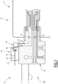
Figure 1 is a detailed, schematic, side view of a storage tank according to an embodiment of the invention, comprising a safety valve in a first configuration ; and -
Figure 2 is a detailed, schematic view of a safety system according to an embodiment of the invention, comprising the safety valve ofFigure 1 in a second configuration. -
Figure 1 shows asafety valve 10 according to an embodiment of the invention. Thesafety valve 10 is part of astorage tank 12. Thestorage tank 12 is configured for storing dihydrogen (H2). - More precisely,
Figure 1 shows astorage tank system 13 according to the invention. Thestorage tank system 13 comprises one ormore storage tanks 12 and a piping system. The piping system comprises at least apipe 14. - In a preferred embodiment, the
storage tank system 13 is situated on board of atransport vehicle 100. - The
safety valve 10, also shown onFigure 2 , comprises : avalve body 16 ; aninner chamber 18 ; agas inlet 20 ; agas exhaust outlet 22 ; aplug 24 ; and adetection device 26. Thegas inlet 20 is connected to thepipe 14. - In the embodiment of
Figures 1 and2 , thesafety valve 10 also comprises avalve seat 30. - The
inner chamber 18 is formed in thevalve body 16. Each of thegas inlet 20 and thegas exhaust outlet 22 opens from theinner chamber 18. Thegas exhaust outlet 22 is connected to an outside of thestorage tank 12. - More precisely, in the embodiment of
Figures 1 and2 , thegas inlet 20 opens on thevalve seat 30. - The
plug 24 comprises a first 38 and a second 40 ends. In the first configuration of thesafety valve 10, shown onFigure 1 , thefirst end 38 is inserted in thegas exhaust outlet 22 and thesecond end 40 is situated outside of thevalve body 16. - In an embodiment, the
first end 38 is coated with alayer 42 of a hot-melt material, such as a metal. In the first configuration of thesafety valve 10, shown onFigure 1 , thelayer 42 maintains thefirst end 38 fixed to thegas exhaust outlet 22. - In the second configuration of the
safety valve 10, shown onFigure 2 , thefirst end 38 of theplug 24 is out of thegas exhaust outlet 22. - The
detection device 26 is coupled to theplug 24 and is configured for being not conductive when said plug is out of thegas exhaust outlet 22. - More specifically, the
safety valve 10 and thedetection device 26 are part of asafety system 50 for thetransport vehicle 100. Thesafety system 50 and thetransport vehicle 100 will be more specifically described below. - In the embodiment of
Figures 1 and2 , thedetection device 26 comprises : asupport 52 ; a first 54 and a second 56 conductors ; and a contactingelement 58. In the embodiment ofFigures 1 and2 , thedetection device 26 also comprises a contactingspring 60. - For example, each of the first 54 and second 56 conductors is a wire.
- The
support 52 is disposed on an external surface of thevalve body 16, outside of theinner chamber 18 and near thegas exhaust outlet 22. A first end of each of the first 54 and the second 56 conductors is fixed to thesupport 52. - The contacting
element 58 comprises acore 62 and aconnector 64, made respectively of an electrically insulator material and of an electrically conductor material. Theconnector 64 is for example a metal pin inserted in thecore 62, each end of the pin emerging from an outer surface of the core. - The contacting
spring 60 extends between a first and a second ends, fixed respectively to thesupport 52 and to the contactingelement 58. - In a compressed state of the contacting
spring 60, shown onFigure 1 , the contactingelement 58 is in a first position relative to thesupport 52. In the first position of the contactingelement 58, each end of theconnector 64 is in contact with the first end, respectively, of the first 54 and of the second 56 conductor. Therefore, in the first position, the contactingelement 58 ensures an electrical contact between the first 54 and the second 56 conductors. - In a relaxed state of the contacting
spring 60, shown onFigure 2 , the contactingelement 58 is in a second position relative to thesupport 52. In the second position of the contactingelement 58, theconnector 64 is distant from the first 54 and second 56 conductors. Therefore, in the second position of the contactingelement 58, the electrical contact between the first 54 and the second 56 conductors is interrupted. - In the first configuration of the
safety valve 10, shown onFigure 1 , thedetection device 26 is in a deactivated conformation, corresponding to theplug 24 being inserted in thegas exhaust outlet 22. - More precisely, in the deactivated conformation, the contacting
element 58 is in contact with thesecond end 40 of theplug 24. Said contact maintains the contactingspring 60 in the compressed state and the contactingelement 58 in the first position. - In the second configuration of the
safety valve 10, shown onFigure 2 , thedetection device 26 is in an activated conformation, corresponding to theplug 24 being out of thegas exhaust outlet 22. - More precisely, in the activated conformation, the contacting
spring 60 is in the relaxed state and the contactingelement 58 is in the second position. - The
safety system 50 will now be described. Thesafety system 50 comprises : at least onesafety valve 10 as described above ; and amonitoring device 70. - The
monitoring device 70 is an electronic device, such as a computer or an electrotechnical device such as a contactor or a relay. - The
detection device 26 of the at least onesafety valve 10 is connected to themonitoring device 70. Preferably, a second end of each of the first 54 and second 56 conductors is connected to themonitoring device 70. - In a preferred embodiment, the
safety system 50 is situated on board of thetransport vehicle 100, said transport vehicle containing at least one, and preferably several storage tanks similar to thestorage tank 12 described above. The or eachstorage tank 12 comprises asafety valve 10 as described above ; and the or eachsafety valve 10 is connected to themonitoring device 70. Preferably, themonitoring device 70 memorizes information regarding a location of the or of eachsafety valve 10 in thetransport vehicle 100. - Preferably, the
several storage tanks 12 are part of thestorage tank system 13 described above. - A method for implementing the
safety system 50 of thetransport vehicle 100 will now be described. - In case of internal overpressure and/or over-temperature in a
storage tank 12 or a group of storage tanks with a TPRD device installed on thestorage tank system 13 storing dihydrogen, pressurized gaseous dihydrogen flows through thegas chamber 18 of thesafety valve 10 of saidstorage tank 12. Under the increase of temperature and/or pressure in theinner chamber 18, thelayer 42 of thefirst end 38 of theplug 24 softens and theplug 24 is ejected from thegas exhaust outlet 22, as shown onFigure 2 . - By over-pressure, we means an increase of the pressure in the
inner chamber 18, and in particular exceeding a preset pressure. More specifically, the preset pressure is over 300 bar, and for example over 650 bar, and more specifically sensibly equal to 700 bar. - By over-temperature, we means an increase of the temperature in the
inner chamber 18, and in particular exceeding a preset temperature. The preset temperature is over 65°C, and for example over 100°C, and more specifically sensibly equal to 110°C. - As the
plug 24 is ejected from thegas exhaust outlet 22, the contactingspring 60 of thedetection device 26 relaxes and the electrical contact between the first 54 and the second 56 conductors is interrupted. Said interruption is detected by themonitoring device 70. Then, for example, themonitoring device 70 emits a warning message regarding the activation of the TPRD of thesafety valve 10, preferably coupled with information about a location, in thetransport vehicle 100, of thestorage tank 12 comprising saidsafety valve 10. An operator is then able to check the safety conditions around saidstorage tank 12 or to initiate safety procedures. - Due to the detection of a TPRD activation, preferably along with a localization of said activated TPRD, the invention allows a quick intervention of operators in case of hazardous conditions in the vehicle. Due to the invention, it is not necessary to provide with a heat detector each safety valve having a TPRD.
Claims (9)
- A safety valve (10) for a storage tank (12) able to store dihydrogen, the safety valve comprising : a valve body (16) ; an inner chamber (18), formed in the valve body ; a gas inlet (20) and a gas exhaust outlet (22), opening in the inner chamber (18) ; and a plug (24), inserted in the gas exhaust outlet (22) ; the plug (24) being configured for being ejected from the gas exhaust outlet (22) in case of an over-pressure and/or of an over-temperature in the inner chamber (18) ;
the safety valve being characterized in that it also comprises a detection device (26) coupled to the plug (24), the detection device being configured for being activated when the plug is ejected from the gas exhaust outlet (22). - A safety valve according to claim 1, wherein the detection device (26) comprises: a support (52) ; a first (54) and a second (56) conductors, fixed to the support ; and a contacting element (58), mobile relative to the support;the detection device (26) being configured so that, in a deactivated conformation, corresponding to the plug (24) being inserted in the gas exhaust outlet (22), the contacting element (58) is in contact with the plug (24) and said contacting element is in a first position relative to the support (52) ; and in an activated conformation, corresponding to the plug (24) being out of the gas exhaust outlet (22), the contacting element (58) is in a second position relative to the support (52);wherein, in the first position, the contacting element (58) ensures an electrical contact between the first (54) and the second (56) conductors ; and in the second position of the contacting element, the electrical contact between the first (54) and second (56) conductors is interrupted.
- A safety valve according to claim 2, wherein the detection device (26) also comprises a compression spring (60) extending between a first and a second ends, fixed respectively to the support (52) and to the contacting element (58) ; and
wherein, in the deactivated conformation of the detection device (26), the compression spring (60) is in a compressed state ; and in the activated conformation of the detection device (26), the compression spring (60) is in a relaxed state. - A storage tank (12), configured for storing dihydrogen, said storage tank comprising a safety valve (10) according to any one of the previous claims.
- A storage tank system (13) comprising : a storage tank (12) according to claim 4 ; and at least one pipe (14), the gas inlet (20) of the safety valve of the storage tank being connected to said at least one pipe (14).
- A safety system (50) for a transport vehicle (100) containing at least one storage tank (12) for storing dihydrogen, the safety system comprising : at least one safety valve (10) according to any one of claims 1 to 3 ; and a monitoring device (70), the detection device (26) of the at least one safety valve being connected to the monitoring device (70).
- A safety system according to claim 6, also comprising at least one pipe (14) coupled to the at least one safety valve (10), the gas inlet (20) of said safety valve being connected to said pipe (14).
- A transport vehicle (100) comprising a safety system (50) according to claim 6 or claim 7.
- A transport vehicle (100) according to claim 8, wherein the monitoring device (70) of the safety system (50) memorizes information regarding a location of the at least one safety valve (10) in the transport vehicle.
Priority Applications (1)
| Application Number | Priority Date | Filing Date | Title |
|---|---|---|---|
| EP23306512.7A EP4524457A1 (en) | 2023-09-12 | 2023-09-12 | Safety valve for a storage tank storing dihydrogen |
Applications Claiming Priority (1)
| Application Number | Priority Date | Filing Date | Title |
|---|---|---|---|
| EP23306512.7A EP4524457A1 (en) | 2023-09-12 | 2023-09-12 | Safety valve for a storage tank storing dihydrogen |
Publications (1)
| Publication Number | Publication Date |
|---|---|
| EP4524457A1 true EP4524457A1 (en) | 2025-03-19 |
Family
ID=88241279
Family Applications (1)
| Application Number | Title | Priority Date | Filing Date |
|---|---|---|---|
| EP23306512.7A Pending EP4524457A1 (en) | 2023-09-12 | 2023-09-12 | Safety valve for a storage tank storing dihydrogen |
Country Status (1)
| Country | Link |
|---|---|
| EP (1) | EP4524457A1 (en) |
Citations (7)
| Publication number | Priority date | Publication date | Assignee | Title |
|---|---|---|---|---|
| EP1295056B1 (en) * | 2000-06-30 | 2005-11-09 | Giat Industries | Safety valve for tank containing a pressurised liquid fluid such as lpg |
| JP4873156B2 (en) * | 2007-01-12 | 2012-02-08 | トヨタ自動車株式会社 | Melting plug |
| US8550105B2 (en) * | 2009-07-03 | 2013-10-08 | Toyota Jidosha Kabushiki Kaisha | Valve system of high pressure tank for vehicle |
| EP3896329A1 (en) | 2020-04-15 | 2021-10-20 | ALSTOM Transport Technologies | Anti-fire safety system for a vehicle having hydrogen stored on board, and related vehicle |
| DE102020207261A1 (en) * | 2020-06-10 | 2021-12-16 | Argo Gmbh | Thermal pressure relief device (TPRD), gas pressure accumulator and gas pressure accumulator system with TPRD and method for thermal overpressure protection |
| DE102020120727A1 (en) * | 2020-08-06 | 2022-02-10 | Bayerische Motoren Werke Aktiengesellschaft | Pressure relief assembly and pressure vessel assembly |
| CN215929214U (en) * | 2021-04-25 | 2022-03-01 | 杭州春江阀门有限公司 | Vehicle-mounted ultrahigh-pressure hydrogen storage cylinder combination valve |
-
2023
- 2023-09-12 EP EP23306512.7A patent/EP4524457A1/en active Pending
Patent Citations (7)
| Publication number | Priority date | Publication date | Assignee | Title |
|---|---|---|---|---|
| EP1295056B1 (en) * | 2000-06-30 | 2005-11-09 | Giat Industries | Safety valve for tank containing a pressurised liquid fluid such as lpg |
| JP4873156B2 (en) * | 2007-01-12 | 2012-02-08 | トヨタ自動車株式会社 | Melting plug |
| US8550105B2 (en) * | 2009-07-03 | 2013-10-08 | Toyota Jidosha Kabushiki Kaisha | Valve system of high pressure tank for vehicle |
| EP3896329A1 (en) | 2020-04-15 | 2021-10-20 | ALSTOM Transport Technologies | Anti-fire safety system for a vehicle having hydrogen stored on board, and related vehicle |
| DE102020207261A1 (en) * | 2020-06-10 | 2021-12-16 | Argo Gmbh | Thermal pressure relief device (TPRD), gas pressure accumulator and gas pressure accumulator system with TPRD and method for thermal overpressure protection |
| DE102020120727A1 (en) * | 2020-08-06 | 2022-02-10 | Bayerische Motoren Werke Aktiengesellschaft | Pressure relief assembly and pressure vessel assembly |
| CN215929214U (en) * | 2021-04-25 | 2022-03-01 | 杭州春江阀门有限公司 | Vehicle-mounted ultrahigh-pressure hydrogen storage cylinder combination valve |
Similar Documents
| Publication | Publication Date | Title |
|---|---|---|
| US11260744B2 (en) | Systems for monitoring volatile fuel system components | |
| US12398818B2 (en) | Thermal pressure relief device (TPRD), gas pressure tank and gas pressure tank system comprising TPRD and method for thermal excess pressure protection | |
| KR101073712B1 (en) | Storage tank system | |
| US9682618B2 (en) | Manual emergency gas release system | |
| CN1178233C (en) | Device for preventing electronic transformer from explosion | |
| US20190358479A1 (en) | Electric-pneumatic actuator assembly | |
| US20110083756A1 (en) | Compressed gas safety discharge system | |
| EP3380779B1 (en) | Composite vessel fire protection system | |
| JP2005315294A (en) | High pressure tank | |
| US7521817B2 (en) | System and method for reducing the chance of fires and/or explosions | |
| CN112584906A (en) | Cartridge monitoring system | |
| US4723573A (en) | Storage tank safety pressure relief methods and systems | |
| EP3129694B1 (en) | Bi-directional hose break-away assembly | |
| US20100252352A1 (en) | System and method for disabling a vehicle | |
| KR20110057716A (en) | Fire safety device for high pressure gas storage system | |
| US3455316A (en) | Safety valve system-structure | |
| US20190193658A1 (en) | Modular safety kit | |
| EP3133687A1 (en) | Container with heating device and safety device | |
| WO2018093307A1 (en) | A method and system for diagnosing at least one pressure relief valve of a liquefied gas fuel system for a vehicle | |
| EP3289250A1 (en) | In-line servicable shutoff valve with excess flow | |
| US12330928B2 (en) | Dispensing system for delivering an operating fluid | |
| EP3909651B1 (en) | EMERGENCY COOLING SYSTEM FOR VEHICLES | |
| EP1473494B1 (en) | Automatic safety device | |
| FR2547250A1 (en) | ANTI-TANK DEPARTURE SYSTEM ON VEHICLE WITH LOADING ARM | |
| JP3373729B2 (en) | Oil mixture prevention mechanism in refueling equipment |
Legal Events
| Date | Code | Title | Description |
|---|---|---|---|
| PUAI | Public reference made under article 153(3) epc to a published international application that has entered the european phase |
Free format text: ORIGINAL CODE: 0009012 |
|
| STAA | Information on the status of an ep patent application or granted ep patent |
Free format text: STATUS: THE APPLICATION HAS BEEN PUBLISHED |
|
| STAA | Information on the status of an ep patent application or granted ep patent |
Free format text: STATUS: REQUEST FOR EXAMINATION WAS MADE |
|
| AK | Designated contracting states |
Kind code of ref document: A1 Designated state(s): AL AT BE BG CH CY CZ DE DK EE ES FI FR GB GR HR HU IE IS IT LI LT LU LV MC ME MK MT NL NO PL PT RO RS SE SI SK SM TR |
|
| 17P | Request for examination filed |
Effective date: 20250305 |
|
| RAP1 | Party data changed (applicant data changed or rights of an application transferred) |
Owner name: ALSTOM TRANSPORT SA |
|
| GRAP | Despatch of communication of intention to grant a patent |
Free format text: ORIGINAL CODE: EPIDOSNIGR1 |
|
| STAA | Information on the status of an ep patent application or granted ep patent |
Free format text: STATUS: GRANT OF PATENT IS INTENDED |
|
| RIC1 | Information provided on ipc code assigned before grant |
Ipc: F17C 13/12 20060101AFI20260212BHEP |
|
| INTG | Intention to grant announced |
Effective date: 20260220 |