EP4524407A1 - A ball lock pin with fail-safe locking mechanism - Google Patents
A ball lock pin with fail-safe locking mechanism Download PDFInfo
- Publication number
- EP4524407A1 EP4524407A1 EP23197431.2A EP23197431A EP4524407A1 EP 4524407 A1 EP4524407 A1 EP 4524407A1 EP 23197431 A EP23197431 A EP 23197431A EP 4524407 A1 EP4524407 A1 EP 4524407A1
- Authority
- EP
- European Patent Office
- Prior art keywords
- pin
- blocking
- blocking pin
- ball
- ball lock
- Prior art date
- Legal status (The legal status is an assumption and is not a legal conclusion. Google has not performed a legal analysis and makes no representation as to the accuracy of the status listed.)
- Granted
Links
Images





Classifications
-
- F—MECHANICAL ENGINEERING; LIGHTING; HEATING; WEAPONS; BLASTING
- F16—ENGINEERING ELEMENTS AND UNITS; GENERAL MEASURES FOR PRODUCING AND MAINTAINING EFFECTIVE FUNCTIONING OF MACHINES OR INSTALLATIONS; THERMAL INSULATION IN GENERAL
- F16B—DEVICES FOR FASTENING OR SECURING CONSTRUCTIONAL ELEMENTS OR MACHINE PARTS TOGETHER, e.g. NAILS, BOLTS, CIRCLIPS, CLAMPS, CLIPS OR WEDGES; JOINTS OR JOINTING
- F16B19/00—Bolts without screw-thread; Pins, including deformable elements; Rivets
- F16B19/04—Rivets; Spigots or the like fastened by riveting
- F16B19/08—Hollow rivets; Multi-part rivets
- F16B19/10—Hollow rivets; Multi-part rivets fastened by expanding mechanically
- F16B19/1027—Multi-part rivets
- F16B19/1036—Blind rivets
- F16B19/109—Temporary rivets, e.g. with a spring-loaded pin
-
- F—MECHANICAL ENGINEERING; LIGHTING; HEATING; WEAPONS; BLASTING
- F16—ENGINEERING ELEMENTS AND UNITS; GENERAL MEASURES FOR PRODUCING AND MAINTAINING EFFECTIVE FUNCTIONING OF MACHINES OR INSTALLATIONS; THERMAL INSULATION IN GENERAL
- F16B—DEVICES FOR FASTENING OR SECURING CONSTRUCTIONAL ELEMENTS OR MACHINE PARTS TOGETHER, e.g. NAILS, BOLTS, CIRCLIPS, CLAMPS, CLIPS OR WEDGES; JOINTS OR JOINTING
- F16B21/00—Means for preventing relative axial movement of a pin, spigot, shaft or the like and a member surrounding it; Stud-and-socket releasable fastenings
- F16B21/10—Means for preventing relative axial movement of a pin, spigot, shaft or the like and a member surrounding it; Stud-and-socket releasable fastenings by separate parts
- F16B21/16—Means for preventing relative axial movement of a pin, spigot, shaft or the like and a member surrounding it; Stud-and-socket releasable fastenings by separate parts with grooves or notches in the pin or shaft
- F16B21/165—Means for preventing relative axial movement of a pin, spigot, shaft or the like and a member surrounding it; Stud-and-socket releasable fastenings by separate parts with grooves or notches in the pin or shaft with balls or rollers
Definitions
- the present invention relates to a ball lock pin comprising a pin body, a blocking pin that is movably arranged in the pin body, at least one locking ball that may be biased into a locking position by the blocking pin, and a spring element that biases the blocking pin into a blocking position for biasing the at least one locking ball into the locking position.
- the present invention further relates to an aircraft comprising such a ball lock pin.
- Conventional ball lock pins usually include a pin body, or outer pin, with a borehole drilled in length direction through the entire outer pin. This borehole is required for accommodation of an inner blocking pin, or lock pin, which is provided for biasing associated locking balls, or lock balls, into designated positions.
- the lock pin in an unactuated state, which corresponds to a locked state of such a conventional ball lock pin, the lock pin is usually pressed against a closure cap by means of a compression spring and, thus, biases the associated lock balls into a locking position.
- the lock pin in an actuated state the lock pin is usually pressed against the biasing force of the compression spring into the outer pin and, thus, releases the associated lock balls from their locking position.
- such a conventional ball lock pin is described in the documents DE 20 2019 106 030 U1 , EP 3 599 385 A1 , US 2007/0001408 A1 , US 2012/0051835 A1 , US 2017/0211607 A1 , US 2019/0314958 A1 , and WO 2017/127773 A1 .
- One solution for avoiding possibly resulting hazardous situations consists in replacing the conventional ball lock pin with a screw connection with a castellated nut and a split or cotter pin.
- Another solution consists in providing the conventional ball lock pin with a securing splint, such as a Fokker needle.
- a ball lock pin which comprises a pin body, a blocking pin, at least one locking ball, a primary spring element, and a redundant spring element.
- the pin body has a length axis and comprises an inner accommodation and at least one locking ball accommodation.
- the blocking pin is at least partly arranged in the inner accommodation and movable along the length axis between a blocking position and a releasing position.
- the at least one locking ball is movably arranged in the at least one locking ball accommodation. More particularly, the at least one locking ball is biased into a locking position by the blocking pin if the blocking pin is in the blocking position and the at least one locking ball is released for moving into an unlocking position if the blocking pin is in the releasing position.
- the primary spring element is arranged in the inner accommodation and biases the blocking pin into the blocking position.
- the redundant spring element is arranged in the inner accommodation and biases the blocking pin into the blocking position.
- the at least one locking ball is still biased into the locking position as the blocking pin is still biased into its blocking position by the redundant spring element.
- the inventive ball lock pin may be provided with a securing feature that prevents unintentional unlocking or unlocking may only be possible by use of a dedicated unlocking tool, as described below.
- the inventive ball lock pin is secured in direction of its length axis in a given component, such as e. g. a hinge, by means of the at least one locking ball which is embedded in the pin body.
- a given component such as e. g. a hinge
- the at least one locking ball may retract into its unlocking position such that the ball lock pin may be inserted into the given component.
- the at least one locking ball is pushed into its locking position and, thus, locks the ball lock pin in the given component.
- the inventive ball lock pin is advantageously provided with a double locking feature.
- the basic component of this double locking feature is the redundant spring element that guarantees locking of the ball lock pin in case of a failure of the primary spring element.
- the inventive ball lock pin is equipped with two independent spring elements in order to realize the double locking feature: the primary spring element and the redundant spring element.
- the inventive ball lock pin is provided with two or more locking balls which may form one or more locking level(s). Furthermore, a closure cap may be provided.
- the closure cap and the blocking pin may comprise corresponding geometries or shapes such that unintentional actuation of the blocking pin is at least rendered more difficult or in the best case even prevented.
- the inventive ball lock pin may either be equipped with two or more locking balls forming a single locking level, or two or more locking levels.
- the inventive ball lock pin is equipped with an inner and an outer blocking pin, which advantageously provides for further redundancy.
- the inventive ball lock pin may either be equipped with two or more locking balls forming a single locking level, or two or more locking levels.
- the closure cap and the inner and outer blocking pins may be shaped such that a dedicated special-shaped actuation tool is required to unlock the ball lock pin. Thus, unintentional unlocking is advantageously prevented.
- the blocking pin(s) and the primary and redundant spring elements are assembled to form a push mechanism.
- a pull mechanism may likewise be realized.
- the pin body comprises an enlarged cup-shaped end section
- the primary spring element is arranged in the enlarged cup-shaped end section, in particular between the blocking pin and the enlarged cup-shaped end section.
- the ball lock pin further comprises a closure cap that closes the enlarged cup-shaped end section.
- the closure cap comprises an opening
- the blocking pin comprises an actuatable end section that extends through the opening.
- the blocking pin comprises a collar that delimits the actuatable end section on the blocking pin, and the primary spring element biases the collar in the blocking position of the blocking pin against the closure cap.
- the blocking pin comprises at least one notch for reception of the at least one locking ball in the releasing position of the blocking pin, and the at least one notch and the collar are arranged on opposed axial ends of the blocking pin.
- the redundant spring element abuts against the blocking pin close to the at least one notch.
- the ball lock pin further comprises at least one additional blocking pin.
- the blocking pin is tube-shaped and comprises an inner through hole, and the at least one additional blocking pin is at least partly accommodated in the inner through hole.
- the at least one additional blocking pin comprises a collar that abuts against the blocking pin.
- the redundant spring element biases the collar of the at least one additional blocking pin against the blocking pin.
- the ball lock pin may comprise at least one additional locking ball
- the pin body may comprise at least one additional locking ball accommodation, wherein the at least one additional locking ball is movably arranged in the at least one additional locking ball accommodation.
- the at least one additional locking ball is biased into an associated locking position by the additional blocking pin if the at least one additional blocking pin is in an associated blocking position, and the at least one additional locking ball is released for moving into an associated unlocking position if the at least one additional blocking pin is in an associated releasing position.
- the at least one locking ball and the at least one additional locking ball may form separate locking levels.
- the blocking pin and the at least one additional blocking pin may be simultaneously actuatable via an associated actuation tool.
- the blocking pin is rotatable about the length axis and comprises at least one lateral flange that is at least lockable in one first angular position or one second angular position.
- the blocking pin is in the releasing position if the blocking pin is locked in the second angular position.
- an aircraft may comprise the ball lock pin described above.
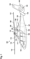
- Figure 1 shows an aircraft 100 that is illustratively embodied as a rotorcraft and, more particularly, as a helicopter.
- the aircraft 100 is hereinafter referred to as the "helicopter 100".
- helicopter 100 the aircraft 100
- application of the present invention is not limited to helicopters. Instead, the present invention may be applied in the complete field of aeronautics, i.e. in any aircrafts or even rockets, and, more generally, in the complete field of engineering.
- the helicopter 100 comprises at least one rotor system 110 that may be embodied as a multi-blade rotor system for providing lift and forward or backward thrust during operation.
- the at least one rotor system 110 comprises a plurality of rotor blades 112, 113 and may be powered by at least one engine 111.
- the plurality of rotor blades 112, 113 are mounted at an associated rotor head 114 to a rotor shaft 115, which rotates in operation of the helicopter 100 around an associated rotation axis.
- the helicopter 100 illustratively further comprises a fuselage 120 that forms an airframe of the helicopter 100.
- the fuselage 120 may be connected to a suitable landing gear and illustratively forms a cabin 123 and a rear fuselage 127.
- the rear fuselage 127 may be connected to a tail boom 130.
- the tail boom 130 may be provided with at least one counter-torque device 140 configured to provide counter-torque during operation, i.e. to counter the torque created by rotation of the plurality of rotor blades 112, 113 around the rotor shaft 115, for purposes of balancing the helicopter 100 in terms of yaw. If desired, the counter-torque device 140 may be shrouded.
- the at least one counter-torque device 140 is provided at an aft section of the tail boom 130 and may have a tail rotor 145.
- the aft section of the tail boom 130 may include a fin 150.
- the tail boom 130 may be provided with a suitable horizontal stabilizer 135.
- the helicopter 100 may comprise a carrier element 160 which may at least cover the at least one engine 111 of the helicopter 100.
- the carrier element 160 may further cover a transmission system of the helicopter 100, which may include a gear box, and/or a crest of the helicopter 100.
- the carrier element 160 may be embodied as a cowling of the helicopter 100 and is, therefore, referred to hereinafter as the "cowling 160", for simplicity and clarity.
- the cowling 160 includes a transmission cowling 170 that covers a transmission system of the helicopter 100, a crest cowling 175 that covers a crest of the helicopter 100, and an engine cowling 180 that covers the at least one engine 111 of the helicopter 100.
- the engine cowling 180 is provided with a cowling access door 185 for providing access to the at least one engine 111.
- the transmission cowling 170 and the crest cowling 175 may also be provided with suitable cowling access doors.
- the cowling access door 185 is preferably pivotally mounted to the engine cowling 180 via suitable hinges 190 for being pivotable between a closed position and an open position.
- suitable hinges 190 may be provided with a ball lock pin according to the present invention, as described below at Figure 11 to Figure 13 .
- Illustrative ball lock pins are described hereinafter with reference to Figure 2 to Figure 10 .
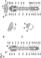
- FIG. 2 shows in parts (A) to (D) a ball lock pin 200 and components thereof according to a first embodiment.
- the ball lock pin 200 comprises a pin body 210, a blocking pin 242, an additional blocking pin 244, at least one locking ball 222, and at least one additional locking ball 224.
- the blocking pin 242 is provided for biasing, in a blocking position, the at least one locking ball 222 into a locking position, and for releasing, in a releasing position, the at least one locking ball 222 such that the at least one locking ball 222 may move into an unlocking position, as described in detail below at Figure 3 .
- the additional blocking pin 244 is provided for biasing, in a blocking position, the at least one additional locking ball 224 into a locking position, and for releasing, in a releasing position, the at least one additional locking ball 224 such that the at least one additional locking ball 224 may move into an unlocking position, as described in detail below at Figure 3 .
- the at least one locking ball 222 and, preferably, two or more locking balls 222 form a first locking level 232.
- a second locking level 234 may be formed by the at least one additional locking ball 224 and, preferably, by two or more additional locking balls 224, as illustrated.
- the locking balls 222 and the additional locking balls 224 are accommodated in the pin body 210, as described in detail below at Figure 3 .
- the pin body 210 illustratively further comprises a collar 214. Moreover, a closure cap 250 is preferably mounted to the pin body 210 in the region of the collar 214.
- part (A) of Figure 2 shows the ball lock pin 200 in an unactuated state.
- the blocking pin 242 and the additional blocking pin 244 are in their respective blocking positions and, thus, the locking balls 222 and the additional locking balls 224 are moved into their respective locking positions.
- the ball lock pin 200 is shown with one blocking pin 242 and one additional blocking pin 244. However, instead of only one additional blocking pin 244, two or more additional blocking pins 244 may likewise be used.
- Part (B) of Figure 2 shows the ball lock pin 200 in an actuated state.
- the blocking pin 242 and the additional blocking pin 244 were moved into their respective releasing positions and, thus, the locking balls 222 and the additional locking balls 224 may move into their respective unlocking positions.
- the blocking pin 242 and the additional blocking pin 244 are moved from their blocking positions according to part (A) into their releasing positions according to part (B) by being pushed into the pin body 210.
- the blocking pin 242 and the additional blocking pin 244 may be moved from their blocking positions into their releasing positions e. g. by being at least partly pushed into the pin body 210.
- Part (C) of Figure 2 shows the blocking pin 242 in more detail, which illustratively comprises a collar 243 that delimits an actuatable end section 241.
- the blocking pin 242 preferably further comprises a ring-shaped notch 245 for reception of the locking balls 222 in their unlocking positions, i.e. in the releasing position of the blocking pin 242, as described in more detail below at Figure 3 .
- the ring-shaped notch 245 and the actuatable end section 241 are preferably arranged on opposed axial ends of the blocking pin 242.
- the blocking pin 242 is tube-shaped and, thus, provided with an inner accommodation formed as an inner through hole 246.
- This inner through hole 246 is preferably provided for accommodation of the additional blocking pin 244.
- Part (D) of Figure 2 shows the additional blocking pin 244 which is, by way of example, essentially rod-shaped so as to fit into the inner through hole 246 of the blocking pin 242. Similar to the blocking pin 242, the additional blocking pin 244 comprises an actuatable end section 249 as well as a ring-shaped notch 248, both of which are illustratively arranged on opposed axial ends of the additional blocking pin 244.
- the ring-shaped notch 248 is provided for reception of the additional locking balls 224 in their unlocking positions, i.e. in the releasing position of the additional blocking pin 244, as described in more detail below at Figure 3 .
- the ring-shaped notch 248 is formed in a collar 247 provided on the additional blocking pin 244.
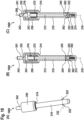
- Figure 3 shows in parts (A) and (B) the ball lock pin 200 of Figure 2 in unactuated and actuated state.
- the ball lock pin 200 comprises the pin body 210, the locking balls 222, the additional locking balls 224, the blocking pin 242, and the additional blocking pin 244.
- the blocking pin 242 comprises the actuatable end section 241, the collar 243, the ring-shaped notch 245, and the inner through hole 246.
- the additional blocking pin 244 comprises the collar 247, the ring-shaped notch 248, and the actuatable end section 249.
- the ball lock pin 200 is provided with the closure cap 250 of Figure 2 and the pin body 210 comprises the collar 214.
- the pin body 210 comprises at least one locking ball accommodation 262.
- two or more locking ball accommodations 262 are provided for accommodation of the locking balls 222.
- the pin body 210 comprises at least one additional locking ball accommodation 264.
- two or more additional locking ball accommodations 264 are provided for accommodation of the additional locking balls 224.
- the pin body 210 comprises an inner accommodation 212.
- the blocking pin 242 and the additional blocking pin 244 are at least partly arranged in the inner accommodation 212 and movable between their respective blocking positions and their respective releasing positions, as described at Figure 2 .
- the additional blocking pin 244 is preferably arranged in the inner through hole 246 of the blocking pin 242 such that the collar 247 of the additional blocking pin 244 abuts against the blocking pin 242 so that the actuatable end sections 241, 249 are positioned coaxially with respect to each other.
- a primary spring element 272 is arranged in the inner accommodation 212 of the pin body 210 and biases the blocking pin 242 into the blocking position.
- a redundant spring element 274 is arranged in the inner accommodation 212 and biases the additional blocking pin 244 into the blocking position.
- the pin body 210 has a closed end that delimits the inner accommodation 212 and supports the redundant spring element 274. Furthermore, the inner accommodation 212 extends at the collar 214 into an enlarged cup-shaped end section 216 and the primary spring element 272 is preferably arranged in the enlarged cup-shaped end section 216, in particular between the blocking pin 242 and the enlarged cup-shaped end section 216.
- the primary spring element 272 biases the collar 243 in the blocking position of the blocking pin 242 against the closure cap 250.
- the closure cap 250 may comprise an opening 252 and the actuatable end section 241 of the blocking pin 242 may at least partly extend through the opening 252.
- the actuatable end section 249 of the additional blocking pin 244 may extend together with the actuatable end section 241 of the blocking pin 242 at least partly through the opening 252.
- part (A) of Figure 3 shows the ball lock pin 200 in the unactuated state.
- the blocking pin 242 and the additional blocking pin 244 are biased by the primary spring element 272 and the redundant spring element 274 into their respective blocking positions and, thus, the locking balls 222 and the additional locking balls 224 are biased by the blocking pin 242 and the additional blocking pin 244 into their respective locking positions.
- the blocking pin 242 and the additional blocking pin 244 were moved against the spring forces of the primary spring element 272 and the redundant spring element 274 along the length axis 218 from their respective blocking positions into their respective releasing positions and, thus, the locking balls 222 and the additional locking balls 224 may move into their respective unlocking positions in the ring-shaped notches 245, 248. More specifically, the collar 243 of the blocking pin 242 acts to compress the primary spring element 272 and the collar 247 of the additional blocking pin 244 acts to compress the redundant spring element 274.
- the ball lock pin 400 is configured to require a specific actuation tool (510 in Figure 5 (B) ) for actuation, as described hereinafter at Figure 5 .
- Figure 5 shows in parts (A) to (D) the ball lock pin 400 of Figure 4 in unactuated and actuated state, as well as components thereof.
- the ball lock pin 400 comprises the pin body 210, the blocking pin 242, the extended additional blocking pin 244, the locking balls 222, and the additional locking balls 224.
- the blocking pin 242 comprises the actuatable end section 241, the collar 243, the ring-shaped notch 245, and the inner through hole 246, and the additional blocking pin 244 comprises the collar 247, the ring-shaped notch 248, and the actuatable end section 249.
- the ball lock pin 400 is provided with the closure cap 250 that comprises the extension 254.
- the ball lock pin 400 is provided with the primary spring element 272 and the redundant spring element 274, and the pin body 210 comprises the collar 214, the enlarged cup-shaped end section 216, the locking ball accommodations 262 as well as the additional locking ball accommodations 264.
- part (A) of Figure 5 shows the ball lock pin 400 with the length axis 218 in the unactuated state.
- the blocking pin 242 and the extended additional blocking pin 244 are biased by the primary spring element 272 and the redundant spring element 274 into their respective blocking positions and, thus, the locking balls 222 and the additional locking balls 224 are biased by the blocking pin 242 and the extended additional blocking pin 244 into their respective locking positions.
- the actuatable end section 241 of the blocking pin 242 is encompassed in radial direction by the extension 254 of the closure cap 250 and the actuatable end section 249 of the extended additional blocking pin 244 extends in direction of the length axis 218 beyond the actuatable end section 241 of the blocking pin 242.
- Part (B) of Figure 5 shows an actuation tool 510 associated with the ball lock pin 400.
- the actuation tool 510 is preferably configured for simultaneous actuation of the blocking pin 242 and the extended additional blocking pin 244, as described below at part (D) of Figure 5 .
- Part (C) of Figure 5 shows the closure cap 250 for further illustrating the extension 254 in axial direction.
- the extension 254 is provided with the opening 252 of the closure cap 250 described above at Figure 3 .
- Part (D) of Figure 5 shows the ball lock pin 400 in the actuated state. Actuation of the ball lock pin 400 is preferably achieved by pushing the blocking pin 242 and the extended additional blocking pin 244 in the actuation direction illustrated with the arrow 290 along the length axis 218 of the pin body 210 and, more generally, of the ball lock pin 400.
- actuation of the ball lock pin 400 preferably initially requires positioning of the actuation tool 510 as illustrated on the ball lock pin 400.
- the actuation tool 510 preferentially comprises an inner geometry, e. g. an inner bore 512 which is suitable to accommodate the part of the actuatable end section 249 of the extended additional blocking pin 244 that extends in direction of the length axis 218 beyond the actuatable end section 241 of the blocking pin 242.
- the blocking pin 242 and the extended additional blocking pin 244 are simultaneously moved against the spring forces of the primary spring element 272 and the redundant spring element 274 along the length axis 218 from their respective blocking positions into their respective releasing positions and, consequently, the locking balls 222 and the additional locking balls 224 may move into their respective unlocking positions in the ring-shaped notches 245, 248.
- the collar 243 of the blocking pin 242 acts to compress the primary spring element 272 and the collar 247 of the extended additional blocking pin 244 acts to compress the redundant spring element 274.
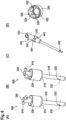
- Figure 6 shows in parts (A) to (D) a ball lock pin 600 and components thereof according to a third embodiment.
- the ball lock pin 600 comprises the pin body 210, the blocking pin 242, and the locking balls 222.
- the pin body 210 comprises the collar 214 and the blocking pin 242 comprises the actuatable end section 241, the collar 243, and the notch 245.
- the ball lock pin 400 is provided with the closure cap 250.
- the ball lock pin 600 does not comprise the additional blocking pin 244 and the additional locking balls 224.
- the blocking pin 242 is now preferably provided with an actuation tool in the form of a transversal rod 610 which is mountable to the actuatable end section 241 of the blocking pin 242, and the notch 245 is now formed by prismatic notches, which are hereinafter commonly referred to as "the prismatic notches 245", for simplicity and brevity.
- the actuatable end section 241 of the blocking pin 242 may be provided with an accommodation e. g. formed by a through hole 612 through which the transversal rod 610 may extend.
- the collar 243 of the blocking pin 242 may be provided with at least one and, illustratively, two laterally extending flanges 641, 643, which are referred to hereinafter as "the lateral flanges 641, 643", for simplicity and brevity.
- Part (D) of Figure 6 shows the closure cap 250 according to the third embodiment of the ball lock pin 600.
- the closure cap 250 may comprise an engaging geometry 620 configured to enable engagement with the lateral flanges 641, 643 of the blocking pin 242.
- the engaging geometry 620 comprises a predetermined number of recesses 622, 624 formed in a support ring 625 provided in the closure cap 250.
- Figure 7 shows in parts (A) and (B) the ball lock pin 600 of Figure 6 in the unactuated and the actuated state, respectively.
- the ball lock pin 600 comprises the pin body 210, the blocking pin 242, and the locking balls 222.
- the blocking pin 242 is equipped with the transversal rod 610 and comprises the actuatable end section 241, the collar 243 that comprises the lateral flanges 641, 643, and the prismatic notches 245.
- the ball lock pin 600 is provided with the closure cap 250 that comprises the engaging geometry 620.
- the ball lock pin 600 is provided with the primary spring element 272 and the redundant spring element 274, and the pin body 210 comprises the locking ball accommodations 262 and the enlarged cup-shaped end section 216.
- part (A) of Figure 7 shows the ball lock pin 600 with the length axis 218 in the unactuated state.
- the blocking pin 242 is biased by the primary spring element 272 and the redundant spring element 274 into the blocking position and, thus, the locking balls 222 are biased by the blocking pin 242 into their locking positions.
- the lateral flange 641, and also the lateral flange 643 of Figure 6 preferably engage the engaging geometry 620, i.e. they are positioned in the recesses 622 of Figure 6 .
- the lateral flange 641, and also the lateral flange 643 of Figure 6 is illustratively locked in a first angular position 702.
- Part (B) of Figure 7 shows the ball lock pin 600 in the actuated state.
- Actuation of the ball lock pin 600 is preferably achieved by initially pushing the blocking pin 242 in the actuation direction illustrated with the arrow 290 along the length axis 218 of the pin body 210 and, more generally, of the ball lock pin 600.
- the blocking pin 242 is moved against the spring forces of the primary spring element 272 and the redundant spring element 274 along the length axis 218, whereby the collar 243 of the blocking pin 242 acts to compress the primary spring element 272 and whereby the blocking pin 242 as such further acts to compress also the redundant spring element 274, as the redundant spring element 274 now preferably abuts against the blocking pin 242 close to the prismatic notches 245.
- the blocking pin 242 may be rotated about the length axis 218 toward a second angular position 704, in which the lateral flanges 641, 643 preferably re-engage the engaging geometry 620, i.e. they are positioned in the recesses 624 of Figure 6 .
- the blocking pin 242 may be locked in the second angular position 704, which corresponds to its releasing position, such that the locking balls 222 may move into the unlocking positions in the prismatic notches 245.
- Figure 8 shows in parts (A) to (D) a ball lock pin 800 and components thereof according to a fourth embodiment.
- the ball lock pin 800 comprises the pin body 210, the blocking pin 242, and the locking balls 222.
- the pin body 210 comprises the collar 214, and the blocking pin 242 is equipped with the transversal rod 610 extending through the through hole 612 and comprises the actuatable end section 241, the collar 243 having the lateral flanges 641, 643, and the prismatic notches 245.
- the ball lock pin 800 is provided with the closure cap 250 that comprises the engaging geometry 620 with the recesses 622, 624 formed in the support ring 625.
- the ball lock pin 800 now comprises the additional locking balls 224 according to Figure 2 and Figure 3 , such that the locking balls 222 and the additional locking balls 224 form again the separate locking levels 232, 234, respectively, as described above at Figure 2 . Therefore, as illustrated in part (C) of Figure 6 the blocking pin 242 is now also provided with the notch 248 according to Figure 2 and Figure 3 which is, however, formed by prismatic notches that are hereinafter commonly referred to as "the prismatic notches 248", for simplicity and brevity.
- the prismatic notches 245 and the prismatic notches 248 are illustrated with an angular offset of 90°.
- an angular offset is not mandatory and may, instead, amount to an arbitrary value between 0° and 360°.
- Figure 9 shows in parts (A) and (B) the ball lock pin 800 of Figure 8 in the unactuated and the actuated state, respectively.
- the ball lock pin 800 comprises the pin body 210, the blocking pin 242, the locking balls 222, and the additional locking balls 224 which are, however, not visible in Figure 9 .
- the blocking pin 242 is equipped with the transversal rod 610 and comprises the actuatable end section 241, the collar 243 that comprises the lateral flange 641, 643, and the prismatic notches 245, 248.
- the ball lock pin 800 is provided with the closure cap 250 that comprises the engaging geometry 620.
- the ball lock pin 800 is provided with the primary spring element 272 and the redundant spring element 274, and the pin body 210 comprises the locking ball accommodations 262, the additional locking ball accommodations 264 which are, however, not visible in Figure 9 , and the enlarged cup-shaped end section 216.
- part (A) of Figure 9 shows the ball lock pin 800 with the length axis 218 in the unactuated state.
- the blocking pin 242 is biased by the primary spring element 272 and the redundant spring element 274 into the blocking position and, thus, the locking balls 222 and the additional locking balls 224 are biased by the blocking pin 242 into their respective locking positions.
- the lateral flange 641, and also the lateral flange 643 of Figure 8 preferably engage the engaging geometry 620, i.e. they are positioned in the recesses 622 of Figure 8 .
- the lateral flange 641, and also the lateral flange 643 of Figure 8 is illustratively locked in the first angular position 702 according to Figure 7 .
- Part (B) of Figure 9 shows the ball lock pin 800 in the actuated state.
- Actuation of the ball lock pin 800 is preferably achieved by initially pushing the blocking pin 242 in the actuation direction illustrated with the arrow 290 along the length axis 218 of the pin body 210 and, more generally, of the ball lock pin 800.
- the blocking pin 242 is moved against the spring forces of the primary spring element 272 and the redundant spring element 274 along the length axis 218, whereby the collar 243 of the blocking pin 242 acts to compress the primary spring element 272 and whereby the blocking pin 242 as such further acts to compress also the redundant spring element 274, as the redundant spring element 274 now preferably abuts against the blocking pin 242 close to the prismatic notches 248.
- the blocking pin 242 may be rotated about the length axis 218 toward a second angular position 704 according to Figure 7 , in which the lateral flanges 641, 643 preferably re-engage the engaging geometry 620, i.e. they may be positioned in the recesses 624 of Figure 8 .
- the blocking pin 242 may be locked in the second angular position 704, which corresponds to its releasing position such that the locking balls 222 and the additional locking balls 224 may move into the unlocking positions in the prismatic notches 245, 248, respectively.
- Figure 10 shows in parts (A) to (C) a ball lock pin 1000 according to a fifth embodiment.
- the ball lock pin 1000 comprises the pin body 210, the blocking pin 242, and the locking balls 222.
- the blocking pin 242 comprises the actuatable end section 241, the collar 243, and the notch 245.
- the ball lock pin 1000 does not comprise the additional blocking pin 244 and the additional locking balls 224.
- the ball lock pin 1000 is provided with the closure cap 250, the primary spring element 272, and the redundant spring element 274. Furthermore, as described above at Figure 2 and Figure 3 , the pin body 210 comprises the collar 214, the enlarged cup-shaped end section 216, and the locking ball accommodations 262.
- part (A) and part (B) of Figure 10 show the ball lock pin 1000 in the unactuated state.
- the blocking pin 242 is biased by the primary spring element 272 and the redundant spring element 274 into the blocking position and, thus, the locking balls 222 are biased by the blocking pin 242 into their locking positions.
- Part (C) of Figure 10 shows the ball lock pin 1000 with the length axis 218 in the actuated state.
- Actuation of the ball lock pin 1000 is preferably achieved similar to Figure 3 by pushing the blocking pin 242 in the actuation direction illustrated with the arrow 290 along the length axis 218 of the pin body 210 and, more generally, of the ball lock pin 1000.
- the blocking pin 242 is moved against the spring forces of the primary spring element 272 and the redundant spring element 274 along the length axis 218, whereby the collar 243 of the blocking pin 242 acts to compress the primary spring element 272 and whereby the blocking pin 242 as such further acts to compress also the redundant spring element 274, as the redundant spring element 274 now preferably abuts against the blocking pin 242 close to the notch 245.
- the locking balls 222 may move into the unlocking positions in the notch 245.
- FIG 11 shows one of the hinges 190 of Figure 1 for further illustrating use of the ball lock pins of Figure 2 to Figure 10 .
- the one of the hinges 190 is hereinafter only referred to as "the hinge 190".
- the hinge 190 comprises three knuckles 1110, 1120, 1130 with leaves 1112, 1122, 1132.
- the leaves 1112, 1122 may be mounted to the engine cowling 180 of Figure 1 and the leaf 1132 may be mounted to the engine cowling access door 185 of Figure 1 .
- the ball lock pin 200 with the locking balls 222 and the additional locking balls 224 is mounted to the knuckles 1110, 1120, 1130.
- the locking balls 222 and the additional locking balls 224 are in their respective locking positions such that the knuckles 1110, 1120, 1130 are fixedly interconnected, so that the leaf 1132 may preferably be rotated relative to the leaves 1112, 1122.
- Figure 12 shows the hinge 190 of Figure 11 during insertion of the ball lock pin 200 into the knuckles 1110, 1120, 1130.
- the knuckle 1130 comprises the leaf 1132.
- the knuckles 1110, 1120, 1130 are initially aligned in order to allow insertion of the ball lock pin 200 thereinto.
- the ball lock pin 200 is then actuated to be in the actuated state according to Figure 3 , part (B), such that the locking balls 222 and the additional locking balls 224 may move into their respective unlocking positions during insertion of the ball lock pin 200 into the knuckles 1110, 1120, 1130.
- the ball lock pin 200 may be inserted into the knuckles 1110, 1120, 1130, illustratively by pushing the ball lock pin 200 in an insertion direction 1210 into the knuckles 1110, 1120, 1130.
- Figure 13 shows the hinge 190 of Figure 11 and Figure 12 after insertion of the ball lock pin 200 into the knuckles 1110, 1120, 1130. More specifically, after insertion of the ball lock pin 200 into the knuckles 1110, 1120, 1130, the ball lock pin 200 may be released and, thus, transition into the unactuated state according to Figure 3 , part (A).
- part (A) in the unactuated state the blocking pin 242 and the additional blocking pin 244 are biased by the primary spring element 272 and the redundant spring element 274 into their respective blocking positions and, thus, the locking balls 222 and the additional locking balls 224 are biased by the blocking pin 242 and the additional blocking pin 244 into their respective locking positions. Biasing of the primary spring element 272 and the redundant spring element 274 is further illustrated with an arrow 1310, and biasing of the locking balls 222 and the additional locking balls 224 is further illustrated with arrows 1320.
- the blocking pin 242 and the additional blocking pin 244 are preferably moved from their blocking positions into their releasing positions by being pushed into the pin body 210.
- the blocking pin 242 and the additional blocking pin 244 may alternatively be moved from their blocking positions into their releasing positions e. g. by being at least partly pulled out of the pin body 210, and so on.
- the hinge 190 is only by way of example shown with the ball lock pin 200 of Figure 2 and Figure 3 .
- any other one of the ball lock pins 400, 600, 800, and 1000 of Figure 4 to Figure 10 may likewise be used.
Landscapes
- Engineering & Computer Science (AREA)
- General Engineering & Computer Science (AREA)
- Mechanical Engineering (AREA)
- Snaps, Bayonet Connections, Set Pins, And Snap Rings (AREA)
Abstract
Description
- The present invention relates to a ball lock pin comprising a pin body, a blocking pin that is movably arranged in the pin body, at least one locking ball that may be biased into a locking position by the blocking pin, and a spring element that biases the blocking pin into a blocking position for biasing the at least one locking ball into the locking position. The present invention further relates to an aircraft comprising such a ball lock pin.
- Conventional ball lock pins usually include a pin body, or outer pin, with a borehole drilled in length direction through the entire outer pin. This borehole is required for accommodation of an inner blocking pin, or lock pin, which is provided for biasing associated locking balls, or lock balls, into designated positions.
- More specifically, in an unactuated state, which corresponds to a locked state of such a conventional ball lock pin, the lock pin is usually pressed against a closure cap by means of a compression spring and, thus, biases the associated lock balls into a locking position. In contrast thereto, in an actuated state the lock pin is usually pressed against the biasing force of the compression spring into the outer pin and, thus, releases the associated lock balls from their locking position.
- By way of example, such a conventional ball lock pin is described in the documents
DE 20 2019 106 030 U1 ,EP 3 599 385 A1 ,US 2007/0001408 A1 ,US 2012/0051835 A1 ,US 2017/0211607 A1 ,US 2019/0314958 A1 , andWO 2017/127773 A1 . - However, such a conventional ball lock pin does not comply with the certification specifications (CS) for helicopters from the European Aviation Safety Agency (EASA), i.e. CS-27.607 and CS-29.607, which require for any removable bolt, screw, nut, pin, or other fastener whose loss could jeopardize safe operation of a given rotorcraft the incorporation of two separate locking devices. Nevertheless, the conventional ball lock pin described above does not fulfil the requirement of these certification specifications.
- More specifically, the design of the conventional ball lock pin has two major flaws regarding the above-mentioned certification specifications: A first problem consists in a possible failure of the compression spring. If this happens, the lock balls are no longer properly pressed into their locking position and the ball lock pin as a whole is no longer secured in its length direction and is, therefore, unable to perform its intended function. A second problem occurs if the lock pin breaks. In this case, a fragment of the lock pin might potentially fall out through the opening in the bottom part of the outer pin, thus, leading again to the problem that the ball lock pin is no longer secured in its length direction. In both cases, failure and loss of the ball lock pin may occur and lead to Foreign Object Damage (FOD).
- One solution for avoiding possibly resulting hazardous situations consists in replacing the conventional ball lock pin with a screw connection with a castellated nut and a split or cotter pin. Another solution consists in providing the conventional ball lock pin with a securing splint, such as a Fokker needle.
- Other ball lock fastener devices are described in the documents
CH 310 313 DE 20 2009 009 338 U1 ,DE 20 2012 001 808 U1 ,EP 0 379 282 A2 ,EP 0 838 600 A1 ,EP 1 707 826 A2 ,EP 2 137 417 A1 ,EP 2 751 434 A1 ,EP 2 801 726 A1 ,EP 2 971 404 A1 ,US 2002/0067045 A1 ,US 2006/0233602 A1 ,US 2014/0030011 A1 ,US 2014/0375020 A1 ,US 2018/0058490 A1 ,US 1,923,025 ,US 2,779,228 ,US 2,816,471 ,US 2,968,205 ,US 3,068,737 ,US 3,085,462 ,US 3,180,390 ,US 3,596,554 , andUS 6,193,261 B1 . - It is an object of the present invention to provide a new ball lock pin with an improved fail-safe locking mechanism. This object is solved by a ball lock pin comprising the features of claim 1.
- More specifically, a ball lock pin is provided which comprises a pin body, a blocking pin, at least one locking ball, a primary spring element, and a redundant spring element. The pin body has a length axis and comprises an inner accommodation and at least one locking ball accommodation. The blocking pin is at least partly arranged in the inner accommodation and movable along the length axis between a blocking position and a releasing position. The at least one locking ball is movably arranged in the at least one locking ball accommodation. More particularly, the at least one locking ball is biased into a locking position by the blocking pin if the blocking pin is in the blocking position and the at least one locking ball is released for moving into an unlocking position if the blocking pin is in the releasing position. The primary spring element is arranged in the inner accommodation and biases the blocking pin into the blocking position. The redundant spring element is arranged in the inner accommodation and biases the blocking pin into the blocking position.
- Advantageously, the inventive ball lock pin is easier to install and/or replace than e. g. a screw connection with a castellated nut and a split or cotter pin, or a conventional ball lock pin with an additional securing splint, such as a Fokker needle. Furthermore, the inventive ball lock pin complies with the EASA certification specifications CS-25.607, CS-27.607, and CS-29.607 concerning double locking for removable fasteners. In particular, the inventive ball lock pin has a fail-safe double locking mechanism provided by means of the redundant spring element that guarantees locking of the ball lock pin in case of a failure of the primary spring element. Likewise, in case of a failure of the blocking pin inside the pin body, the at least one locking ball is still biased into the locking position as the blocking pin is still biased into its blocking position by the redundant spring element. Moreover, the inventive ball lock pin may be provided with a securing feature that prevents unintentional unlocking or unlocking may only be possible by use of a dedicated unlocking tool, as described below.
- In general, the inventive ball lock pin is secured in direction of its length axis in a given component, such as e. g. a hinge, by means of the at least one locking ball which is embedded in the pin body. By moving the blocking pin into its releasing position, the at least one locking ball may retract into its unlocking position such that the ball lock pin may be inserted into the given component. By subsequently moving the blocking pin into its blocking position, the at least one locking ball is pushed into its locking position and, thus, locks the ball lock pin in the given component.
- However, in order to prevent failure of the inventive ball lock pin, the latter is advantageously provided with a double locking feature. The basic component of this double locking feature is the redundant spring element that guarantees locking of the ball lock pin in case of a failure of the primary spring element. In other words, the inventive ball lock pin is equipped with two independent spring elements in order to realize the double locking feature: the primary spring element and the redundant spring element. A respective axial securing/locking of the inventive ball lock pin, i.e. a securing/locking in the direction of its length axis, is ensured by the at least one locking ball.
- Advantageously, the inventive ball lock pin is provided with two or more locking balls which may form one or more locking level(s). Furthermore, a closure cap may be provided.
- In an illustrative configuration, the closure cap and the blocking pin may comprise corresponding geometries or shapes such that unintentional actuation of the blocking pin is at least rendered more difficult or in the best case even prevented. In this configuration, the inventive ball lock pin may either be equipped with two or more locking balls forming a single locking level, or two or more locking levels.
- In another illustrative configuration, the inventive ball lock pin is equipped with an inner and an outer blocking pin, which advantageously provides for further redundancy. Again, the inventive ball lock pin may either be equipped with two or more locking balls forming a single locking level, or two or more locking levels. In this configuration, the closure cap and the inner and outer blocking pins may be shaped such that a dedicated special-shaped actuation tool is required to unlock the ball lock pin. Thus, unintentional unlocking is advantageously prevented.
- By way of example, the blocking pin(s) and the primary and redundant spring elements are assembled to form a push mechanism. However, a pull mechanism may likewise be realized.
- In some embodiments, the pin body comprises an enlarged cup-shaped end section, and the primary spring element is arranged in the enlarged cup-shaped end section, in particular between the blocking pin and the enlarged cup-shaped end section.
- In some embodiments, the ball lock pin further comprises a closure cap that closes the enlarged cup-shaped end section. The closure cap comprises an opening, and the blocking pin comprises an actuatable end section that extends through the opening.
- Preferably, the blocking pin comprises a collar that delimits the actuatable end section on the blocking pin, and the primary spring element biases the collar in the blocking position of the blocking pin against the closure cap.
- Preferably, the blocking pin comprises at least one notch for reception of the at least one locking ball in the releasing position of the blocking pin, and the at least one notch and the collar are arranged on opposed axial ends of the blocking pin.
- Preferably, the redundant spring element abuts against the blocking pin close to the at least one notch.
- In some embodiments, the ball lock pin further comprises at least one additional blocking pin.
- Preferably, the blocking pin is tube-shaped and comprises an inner through hole, and the at least one additional blocking pin is at least partly accommodated in the inner through hole.
- Preferably, the at least one additional blocking pin comprises a collar that abuts against the blocking pin.
- Preferably, the redundant spring element biases the collar of the at least one additional blocking pin against the blocking pin.
- The ball lock pin may comprise at least one additional locking ball, and the pin body may comprise at least one additional locking ball accommodation, wherein the at least one additional locking ball is movably arranged in the at least one additional locking ball accommodation. Preferably, the at least one additional locking ball is biased into an associated locking position by the additional blocking pin if the at least one additional blocking pin is in an associated blocking position, and the at least one additional locking ball is released for moving into an associated unlocking position if the at least one additional blocking pin is in an associated releasing position. The at least one locking ball and the at least one additional locking ball may form separate locking levels.
- The blocking pin and the at least one additional blocking pin may be simultaneously actuatable via an associated actuation tool.
- In some embodiments, the blocking pin is rotatable about the length axis and comprises at least one lateral flange that is at least lockable in one first angular position or one second angular position.
- Preferably, the blocking pin is in the releasing position if the blocking pin is locked in the second angular position.
- According to one aspect of the present invention, an aircraft may comprise the ball lock pin described above.
- Preferred embodiments of the present invention are outlined by way of example in the following description with reference to the attached drawings. In these attached drawings, identical or identically functioning components and elements are labeled with identical reference numbers and characters and are, consequently, only described once in the following description.
-
Figure 1 shows a side view of an illustrative aircraft with hinges which are equipped with ball lock pins according to the present invention, -
Figure 2 shows perspective views of a ball lock pin according to a first embodiment, -
Figure 3 shows cut views of the ball lock pin ofFigure 2 , -
Figure 4 shows perspective views of a ball lock pin according to a second embodiment, -
Figure 5 shows cut views of the ball lock pin ofFigure 4 , -
Figure 6 shows perspective views of a ball lock pin according to a third embodiment, -
Figure 7 shows cut views of the ball lock pin ofFigure 6 , -
Figure 8 shows perspective views of a ball lock pin according to a fourth embodiment, -
Figure 9 shows cut views of the ball lock pin ofFigure 8 , -
Figure 10 shows a perspective view and cut views of a ball lock pin according to a fifth embodiment, -
Figure 11 shows a perspective view of one of the hinges ofFigure 1 with the ball lock pin ofFigure 2 , -
Figure 12 shows a cut view of the hinge ofFigure 11 with the ball lock pin ofFigure 11 in actuated state, and -
Figure 13 shows a cut view of the hinge ofFigure 11 with the ball lock pin ofFigure 11 in unactuated state. -
Figure 1 shows anaircraft 100 that is illustratively embodied as a rotorcraft and, more particularly, as a helicopter. Thus, for purposes of simplicity and clarity, theaircraft 100 is hereinafter referred to as the "helicopter 100". However, it should be noted that application of the present invention is not limited to helicopters. Instead, the present invention may be applied in the complete field of aeronautics, i.e. in any aircrafts or even rockets, and, more generally, in the complete field of engineering. - Illustratively, the
helicopter 100 comprises at least onerotor system 110 that may be embodied as a multi-blade rotor system for providing lift and forward or backward thrust during operation. The at least onerotor system 110 comprises a plurality ofrotor blades engine 111. By way of example, the plurality ofrotor blades rotor head 114 to arotor shaft 115, which rotates in operation of thehelicopter 100 around an associated rotation axis. - The
helicopter 100 illustratively further comprises afuselage 120 that forms an airframe of thehelicopter 100. Thefuselage 120 may be connected to a suitable landing gear and illustratively forms acabin 123 and arear fuselage 127. Therear fuselage 127 may be connected to atail boom 130. - The
tail boom 130 may be provided with at least onecounter-torque device 140 configured to provide counter-torque during operation, i.e. to counter the torque created by rotation of the plurality ofrotor blades rotor shaft 115, for purposes of balancing thehelicopter 100 in terms of yaw. If desired, thecounter-torque device 140 may be shrouded. - Illustratively, the at least one
counter-torque device 140 is provided at an aft section of thetail boom 130 and may have atail rotor 145. The aft section of thetail boom 130 may include a fin 150. Furthermore, thetail boom 130 may be provided with a suitablehorizontal stabilizer 135. - Moreover, the
helicopter 100 may comprise acarrier element 160 which may at least cover the at least oneengine 111 of thehelicopter 100. If desired, thecarrier element 160 may further cover a transmission system of thehelicopter 100, which may include a gear box, and/or a crest of thehelicopter 100. More specifically, thecarrier element 160 may be embodied as a cowling of thehelicopter 100 and is, therefore, referred to hereinafter as the "cowling 160", for simplicity and clarity. Illustratively, thecowling 160 includes atransmission cowling 170 that covers a transmission system of thehelicopter 100, acrest cowling 175 that covers a crest of thehelicopter 100, and anengine cowling 180 that covers the at least oneengine 111 of thehelicopter 100. - By way of example, the
engine cowling 180 is provided with acowling access door 185 for providing access to the at least oneengine 111. Likewise, thetransmission cowling 170 and thecrest cowling 175 may also be provided with suitable cowling access doors. - The
cowling access door 185 is preferably pivotally mounted to theengine cowling 180 viasuitable hinges 190 for being pivotable between a closed position and an open position. One or more of thehinges 190 may be provided with a ball lock pin according to the present invention, as described below atFigure 11 to Figure 13 . Illustrative ball lock pins are described hereinafter with reference toFigure 2 to Figure 10 . -
Figure 2 shows in parts (A) to (D) aball lock pin 200 and components thereof according to a first embodiment. Theball lock pin 200 comprises apin body 210, a blockingpin 242, anadditional blocking pin 244, at least onelocking ball 222, and at least oneadditional locking ball 224. - The blocking
pin 242 is provided for biasing, in a blocking position, the at least onelocking ball 222 into a locking position, and for releasing, in a releasing position, the at least onelocking ball 222 such that the at least onelocking ball 222 may move into an unlocking position, as described in detail below atFigure 3 . Similarly, theadditional blocking pin 244 is provided for biasing, in a blocking position, the at least oneadditional locking ball 224 into a locking position, and for releasing, in a releasing position, the at least oneadditional locking ball 224 such that the at least oneadditional locking ball 224 may move into an unlocking position, as described in detail below atFigure 3 . - By way of example, the at least one
locking ball 222 and, preferably, two ormore locking balls 222 form afirst locking level 232. Asecond locking level 234 may be formed by the at least oneadditional locking ball 224 and, preferably, by two or more additional lockingballs 224, as illustrated. The lockingballs 222 and the additional lockingballs 224 are accommodated in thepin body 210, as described in detail below atFigure 3 . - The
pin body 210 illustratively further comprises acollar 214. Moreover, aclosure cap 250 is preferably mounted to thepin body 210 in the region of thecollar 214. - More particularly, part (A) of
Figure 2 shows theball lock pin 200 in an unactuated state. In this unactuated state, the blockingpin 242 and theadditional blocking pin 244 are in their respective blocking positions and, thus, the lockingballs 222 and the additional lockingballs 224 are moved into their respective locking positions. - At this point, it should be noted that the
ball lock pin 200 is shown with oneblocking pin 242 and oneadditional blocking pin 244. However, instead of only oneadditional blocking pin 244, two or more additional blocking pins 244 may likewise be used. - Part (B) of
Figure 2 shows theball lock pin 200 in an actuated state. In this actuated state, the blockingpin 242 and theadditional blocking pin 244 were moved into their respective releasing positions and, thus, the lockingballs 222 and the additional lockingballs 224 may move into their respective unlocking positions. - By way of example, the blocking
pin 242 and theadditional blocking pin 244 are moved from their blocking positions according to part (A) into their releasing positions according to part (B) by being pushed into thepin body 210. Alternatively, the blockingpin 242 and theadditional blocking pin 244 may be moved from their blocking positions into their releasing positions e. g. by being at least partly pushed into thepin body 210. - Part (C) of
Figure 2 shows the blockingpin 242 in more detail, which illustratively comprises acollar 243 that delimits anactuatable end section 241. The blockingpin 242 preferably further comprises a ring-shapednotch 245 for reception of the lockingballs 222 in their unlocking positions, i.e. in the releasing position of the blockingpin 242, as described in more detail below atFigure 3 . The ring-shapednotch 245 and theactuatable end section 241 are preferably arranged on opposed axial ends of the blockingpin 242. - Illustratively, the blocking
pin 242 is tube-shaped and, thus, provided with an inner accommodation formed as an inner throughhole 246. This inner throughhole 246 is preferably provided for accommodation of theadditional blocking pin 244. - Part (D) of
Figure 2 shows theadditional blocking pin 244 which is, by way of example, essentially rod-shaped so as to fit into the inner throughhole 246 of the blockingpin 242. Similar to theblocking pin 242, theadditional blocking pin 244 comprises anactuatable end section 249 as well as a ring-shapednotch 248, both of which are illustratively arranged on opposed axial ends of theadditional blocking pin 244. - The ring-shaped
notch 248 is provided for reception of the additional lockingballs 224 in their unlocking positions, i.e. in the releasing position of theadditional blocking pin 244, as described in more detail below atFigure 3 . By way of example, the ring-shapednotch 248 is formed in acollar 247 provided on theadditional blocking pin 244. -
Figure 3 shows in parts (A) and (B) theball lock pin 200 ofFigure 2 in unactuated and actuated state. As described atFigure 2 , theball lock pin 200 comprises thepin body 210, the lockingballs 222, the additional lockingballs 224, the blockingpin 242, and theadditional blocking pin 244. The blockingpin 242 comprises theactuatable end section 241, thecollar 243, the ring-shapednotch 245, and the inner throughhole 246. Theadditional blocking pin 244 comprises thecollar 247, the ring-shapednotch 248, and theactuatable end section 249. Furthermore, theball lock pin 200 is provided with theclosure cap 250 ofFigure 2 and thepin body 210 comprises thecollar 214. - More specifically, the
pin body 210 comprises at least onelocking ball accommodation 262. Preferably, two or morelocking ball accommodations 262 are provided for accommodation of the lockingballs 222. Likewise, thepin body 210 comprises at least one additionallocking ball accommodation 264. Preferably, two or more additionallocking ball accommodations 264 are provided for accommodation of the additional lockingballs 224. - Furthermore, the
pin body 210 comprises aninner accommodation 212. The blockingpin 242 and theadditional blocking pin 244 are at least partly arranged in theinner accommodation 212 and movable between their respective blocking positions and their respective releasing positions, as described atFigure 2 . Thereby, theadditional blocking pin 244 is preferably arranged in the inner throughhole 246 of the blockingpin 242 such that thecollar 247 of theadditional blocking pin 244 abuts against the blockingpin 242 so that theactuatable end sections - Moreover, a
primary spring element 272 is arranged in theinner accommodation 212 of thepin body 210 and biases the blockingpin 242 into the blocking position. Similarly, aredundant spring element 274 is arranged in theinner accommodation 212 and biases theadditional blocking pin 244 into the blocking position. - Illustratively, the
pin body 210 has a closed end that delimits theinner accommodation 212 and supports theredundant spring element 274. Furthermore, theinner accommodation 212 extends at thecollar 214 into an enlarged cup-shapedend section 216 and theprimary spring element 272 is preferably arranged in the enlarged cup-shapedend section 216, in particular between the blockingpin 242 and the enlarged cup-shapedend section 216. - By way of example, the
primary spring element 272 biases thecollar 243 in the blocking position of the blockingpin 242 against theclosure cap 250. For instance, theclosure cap 250 may comprise anopening 252 and theactuatable end section 241 of the blockingpin 242 may at least partly extend through theopening 252. Thus, theactuatable end section 249 of theadditional blocking pin 244 may extend together with theactuatable end section 241 of the blockingpin 242 at least partly through theopening 252. - Furthermore, the
redundant spring element 274 illustratively abuts against theadditional blocking pin 244 close to thenotch 248 and, more particularly, against thecollar 247. Thus, theredundant spring element 274 biases thecollar 247 against the blockingpin 242 and, therefore, also biases thecollar 243 of the blockingpin 242 in the blocking position of the blockingpin 242 against theclosure cap 250. - More particularly, part (A) of
Figure 3 shows theball lock pin 200 in the unactuated state. In this unactuated state, the blockingpin 242 and theadditional blocking pin 244 are biased by theprimary spring element 272 and theredundant spring element 274 into their respective blocking positions and, thus, the lockingballs 222 and the additional lockingballs 224 are biased by the blockingpin 242 and theadditional blocking pin 244 into their respective locking positions. - Part (B) of
Figure 3 , in turn, shows theball lock pin 200 in the actuated state. Actuation of theball lock pin 200 is preferably achieved by pushing the blockingpin 242 and theadditional blocking pin 244 in an actuation direction illustrated with anarrow 290 along alength axis 218 of thepin body 210 and, more generally, of theball lock pin 200. - In the actuated state, the blocking
pin 242 and theadditional blocking pin 244 were moved against the spring forces of theprimary spring element 272 and theredundant spring element 274 along thelength axis 218 from their respective blocking positions into their respective releasing positions and, thus, the lockingballs 222 and the additional lockingballs 224 may move into their respective unlocking positions in the ring-shapednotches collar 243 of the blockingpin 242 acts to compress theprimary spring element 272 and thecollar 247 of theadditional blocking pin 244 acts to compress theredundant spring element 274. -
Figure 4 shows in parts (A) to (D) aball lock pin 400 and components thereof according to a second embodiment. Similar to theball lock pin 200 ofFigure 2 andFigure 3 , theball lock pin 400 comprises thepin body 210, the blockingpin 242, theadditional blocking pin 244, the lockingballs 222, and the additional lockingballs 224. Furthermore, similar to theball lock pin 200 ofFigure 2 andFigure 3 , the blockingpin 242 comprises theactuatable end section 241, thecollar 243, the ring-shapednotch 245, and the inner throughhole 246, and theadditional blocking pin 244 comprises thecollar 247, the ring-shapednotch 248, and theactuatable end section 249. Moreover, similar to theball lock pin 200 ofFigure 2 andFigure 3 , theball lock pin 400 is provided with theclosure cap 250 and thepin body 210 comprises thecollar 214. - However, in contrast to the
ball lock pin 200 ofFigure 2 andFigure 3 , theadditional blocking pin 244 is now extended and theclosure cap 250 is now provided with anextension 254. Thus, theball lock pin 400 is configured to require a specific actuation tool (510 inFigure 5 (B) ) for actuation, as described hereinafter atFigure 5 . -
Figure 5 shows in parts (A) to (D) theball lock pin 400 ofFigure 4 in unactuated and actuated state, as well as components thereof. As described atFigure 4 , theball lock pin 400 comprises thepin body 210, the blockingpin 242, the extendedadditional blocking pin 244, the lockingballs 222, and the additional lockingballs 224. The blockingpin 242 comprises theactuatable end section 241, thecollar 243, the ring-shapednotch 245, and the inner throughhole 246, and theadditional blocking pin 244 comprises thecollar 247, the ring-shapednotch 248, and theactuatable end section 249. Moreover, theball lock pin 400 is provided with theclosure cap 250 that comprises theextension 254. Furthermore, similar to theball lock pin 200 ofFigure 2 andFigure 3 , theball lock pin 400 is provided with theprimary spring element 272 and theredundant spring element 274, and thepin body 210 comprises thecollar 214, the enlarged cup-shapedend section 216, the lockingball accommodations 262 as well as the additionallocking ball accommodations 264. - More specifically, part (A) of
Figure 5 shows theball lock pin 400 with thelength axis 218 in the unactuated state. In this unactuated state, the blockingpin 242 and the extendedadditional blocking pin 244 are biased by theprimary spring element 272 and theredundant spring element 274 into their respective blocking positions and, thus, the lockingballs 222 and the additional lockingballs 224 are biased by the blockingpin 242 and the extendedadditional blocking pin 244 into their respective locking positions. In their respective blocking positions, theactuatable end section 241 of the blockingpin 242 is encompassed in radial direction by theextension 254 of theclosure cap 250 and theactuatable end section 249 of the extendedadditional blocking pin 244 extends in direction of thelength axis 218 beyond theactuatable end section 241 of the blockingpin 242. - Part (B) of
Figure 5 shows anactuation tool 510 associated with theball lock pin 400. Theactuation tool 510 is preferably configured for simultaneous actuation of the blockingpin 242 and the extendedadditional blocking pin 244, as described below at part (D) ofFigure 5 . - Part (C) of
Figure 5 shows theclosure cap 250 for further illustrating theextension 254 in axial direction. Theextension 254 is provided with theopening 252 of theclosure cap 250 described above atFigure 3 . - Part (D) of
Figure 5 shows theball lock pin 400 in the actuated state. Actuation of theball lock pin 400 is preferably achieved by pushing the blockingpin 242 and the extendedadditional blocking pin 244 in the actuation direction illustrated with thearrow 290 along thelength axis 218 of thepin body 210 and, more generally, of theball lock pin 400. - More specifically, actuation of the
ball lock pin 400 preferably initially requires positioning of theactuation tool 510 as illustrated on theball lock pin 400. Theactuation tool 510 preferentially comprises an inner geometry, e. g. aninner bore 512 which is suitable to accommodate the part of theactuatable end section 249 of the extendedadditional blocking pin 244 that extends in direction of thelength axis 218 beyond theactuatable end section 241 of the blockingpin 242. Thus, by pushing theactuation tool 510 in the direction of thearrow 290 the blockingpin 242 and the extendedadditional blocking pin 244 are simultaneously moved against the spring forces of theprimary spring element 272 and theredundant spring element 274 along thelength axis 218 from their respective blocking positions into their respective releasing positions and, consequently, the lockingballs 222 and the additional lockingballs 224 may move into their respective unlocking positions in the ring-shapednotches collar 243 of the blockingpin 242 acts to compress theprimary spring element 272 and thecollar 247 of the extendedadditional blocking pin 244 acts to compress theredundant spring element 274. -
Figure 6 shows in parts (A) to (D) aball lock pin 600 and components thereof according to a third embodiment. Similar to theball lock pin 200 ofFigure 2 andFigure 3 , theball lock pin 600 comprises thepin body 210, the blockingpin 242, and the lockingballs 222. Furthermore, similar to theball lock pin 200 ofFigure 2 andFigure 3 , thepin body 210 comprises thecollar 214 and the blockingpin 242 comprises theactuatable end section 241, thecollar 243, and thenotch 245. Moreover, similar to theball lock pin 200 ofFigure 2 andFigure 3 , theball lock pin 400 is provided with theclosure cap 250. - However, in contrast to the
ball lock pin 200 ofFigure 2 andFigure 3 , theball lock pin 600 does not comprise theadditional blocking pin 244 and the additional lockingballs 224. Instead, as illustrated in part (C) ofFigure 6 theblocking pin 242 is now preferably provided with an actuation tool in the form of atransversal rod 610 which is mountable to theactuatable end section 241 of the blockingpin 242, and thenotch 245 is now formed by prismatic notches, which are hereinafter commonly referred to as "theprismatic notches 245", for simplicity and brevity. - More specifically, as illustrated in part (C) of
Figure 6 theactuatable end section 241 of the blockingpin 242 may be provided with an accommodation e. g. formed by a throughhole 612 through which thetransversal rod 610 may extend. Furthermore, thecollar 243 of the blockingpin 242 may be provided with at least one and, illustratively, two laterally extendingflanges lateral flanges - Part (D) of
Figure 6 shows theclosure cap 250 according to the third embodiment of theball lock pin 600. More specifically, theclosure cap 250 may comprise an engaginggeometry 620 configured to enable engagement with thelateral flanges pin 242. Illustratively, the engaginggeometry 620 comprises a predetermined number ofrecesses support ring 625 provided in theclosure cap 250. -
Figure 7 shows in parts (A) and (B) theball lock pin 600 ofFigure 6 in the unactuated and the actuated state, respectively. As described atFigure 6 , theball lock pin 600 comprises thepin body 210, the blockingpin 242, and the lockingballs 222. The blockingpin 242 is equipped with thetransversal rod 610 and comprises theactuatable end section 241, thecollar 243 that comprises thelateral flanges prismatic notches 245. Moreover, theball lock pin 600 is provided with theclosure cap 250 that comprises the engaginggeometry 620. Furthermore, similar to theball lock pin 200 ofFigure 2 andFigure 3 , theball lock pin 600 is provided with theprimary spring element 272 and theredundant spring element 274, and thepin body 210 comprises the lockingball accommodations 262 and the enlarged cup-shapedend section 216. - More specifically, part (A) of
Figure 7 shows theball lock pin 600 with thelength axis 218 in the unactuated state. In this unactuated state, the blockingpin 242 is biased by theprimary spring element 272 and theredundant spring element 274 into the blocking position and, thus, the lockingballs 222 are biased by the blockingpin 242 into their locking positions. In the blocking position, thelateral flange 641, and also thelateral flange 643 ofFigure 6 , preferably engage the engaginggeometry 620, i.e. they are positioned in therecesses 622 ofFigure 6 . Thus, thelateral flange 641, and also thelateral flange 643 ofFigure 6 , is illustratively locked in a firstangular position 702. - Part (B) of
Figure 7 shows theball lock pin 600 in the actuated state. Actuation of theball lock pin 600 is preferably achieved by initially pushing the blockingpin 242 in the actuation direction illustrated with thearrow 290 along thelength axis 218 of thepin body 210 and, more generally, of theball lock pin 600. Thus, the blockingpin 242 is moved against the spring forces of theprimary spring element 272 and theredundant spring element 274 along thelength axis 218, whereby thecollar 243 of the blockingpin 242 acts to compress theprimary spring element 272 and whereby the blockingpin 242 as such further acts to compress also theredundant spring element 274, as theredundant spring element 274 now preferably abuts against the blockingpin 242 close to theprismatic notches 245. Then, the blockingpin 242 may be rotated about thelength axis 218 toward a secondangular position 704, in which thelateral flanges geometry 620, i.e. they are positioned in therecesses 624 ofFigure 6 . Thus, the blockingpin 242 may be locked in the secondangular position 704, which corresponds to its releasing position, such that the lockingballs 222 may move into the unlocking positions in theprismatic notches 245. -
Figure 8 shows in parts (A) to (D) aball lock pin 800 and components thereof according to a fourth embodiment. Similar to theball lock pin 600 ofFigure 6 andFigure 7 , theball lock pin 800 comprises thepin body 210, the blockingpin 242, and the lockingballs 222. Furthermore, similar to theball lock pin 600 ofFigure 6 andFigure 7 , thepin body 210 comprises thecollar 214, and the blockingpin 242 is equipped with thetransversal rod 610 extending through the throughhole 612 and comprises theactuatable end section 241, thecollar 243 having thelateral flanges prismatic notches 245. Moreover, similar to theball lock pin 600 ofFigure 6 andFigure 7 , theball lock pin 800 is provided with theclosure cap 250 that comprises the engaginggeometry 620 with therecesses support ring 625. - However, in contrast to the
ball lock pin 600 ofFigure 6 andFigure 7 , theball lock pin 800 now comprises the additional lockingballs 224 according toFigure 2 andFigure 3 , such that the lockingballs 222 and the additional lockingballs 224 form again theseparate locking levels Figure 2 . Therefore, as illustrated in part (C) ofFigure 6 theblocking pin 242 is now also provided with thenotch 248 according toFigure 2 andFigure 3 which is, however, formed by prismatic notches that are hereinafter commonly referred to as "theprismatic notches 248", for simplicity and brevity. - By way of example, in part (C) of
Figure 8 theprismatic notches 245 and theprismatic notches 248 are illustrated with an angular offset of 90°. However, such an angular offset is not mandatory and may, instead, amount to an arbitrary value between 0° and 360°. -
Figure 9 shows in parts (A) and (B) theball lock pin 800 ofFigure 8 in the unactuated and the actuated state, respectively. As described atFigure 8 , theball lock pin 800 comprises thepin body 210, the blockingpin 242, the lockingballs 222, and the additional lockingballs 224 which are, however, not visible inFigure 9 . The blockingpin 242 is equipped with thetransversal rod 610 and comprises theactuatable end section 241, thecollar 243 that comprises thelateral flange prismatic notches ball lock pin 800 is provided with theclosure cap 250 that comprises the engaginggeometry 620. Furthermore, similar to theball lock pin 600 ofFigure 6 andFigure 7 , theball lock pin 800 is provided with theprimary spring element 272 and theredundant spring element 274, and thepin body 210 comprises the lockingball accommodations 262, the additionallocking ball accommodations 264 which are, however, not visible inFigure 9 , and the enlarged cup-shapedend section 216. - More specifically, part (A) of
Figure 9 shows theball lock pin 800 with thelength axis 218 in the unactuated state. In this unactuated state, the blockingpin 242 is biased by theprimary spring element 272 and theredundant spring element 274 into the blocking position and, thus, the lockingballs 222 and the additional lockingballs 224 are biased by the blockingpin 242 into their respective locking positions. In the blocking position, thelateral flange 641, and also thelateral flange 643 ofFigure 8 , preferably engage the engaginggeometry 620, i.e. they are positioned in therecesses 622 ofFigure 8 . Thus, thelateral flange 641, and also thelateral flange 643 ofFigure 8 , is illustratively locked in the firstangular position 702 according toFigure 7 . - Part (B) of
Figure 9 shows theball lock pin 800 in the actuated state. Actuation of theball lock pin 800 is preferably achieved by initially pushing the blockingpin 242 in the actuation direction illustrated with thearrow 290 along thelength axis 218 of thepin body 210 and, more generally, of theball lock pin 800. Thus, the blockingpin 242 is moved against the spring forces of theprimary spring element 272 and theredundant spring element 274 along thelength axis 218, whereby thecollar 243 of the blockingpin 242 acts to compress theprimary spring element 272 and whereby the blockingpin 242 as such further acts to compress also theredundant spring element 274, as theredundant spring element 274 now preferably abuts against the blockingpin 242 close to theprismatic notches 248. Then, the blockingpin 242 may be rotated about thelength axis 218 toward a secondangular position 704 according toFigure 7 , in which thelateral flanges geometry 620, i.e. they may be positioned in therecesses 624 ofFigure 8 . Thus, the blockingpin 242 may be locked in the secondangular position 704, which corresponds to its releasing position such that the lockingballs 222 and the additional lockingballs 224 may move into the unlocking positions in theprismatic notches -
Figure 10 shows in parts (A) to (C) aball lock pin 1000 according to a fifth embodiment. Similar to theball lock pin 200 ofFigure 2 andFigure 3 , theball lock pin 1000 comprises thepin body 210, the blockingpin 242, and the lockingballs 222. As described above atFigure 2 andFigure 3 , the blockingpin 242 comprises theactuatable end section 241, thecollar 243, and thenotch 245. However, in contrast to theball lock pin 200 ofFigure 2 andFigure 3 , theball lock pin 1000 does not comprise theadditional blocking pin 244 and the additional lockingballs 224. - Moreover, similar to the
ball lock pin 200 ofFigure 2 andFigure 3 , theball lock pin 1000 is provided with theclosure cap 250, theprimary spring element 272, and theredundant spring element 274. Furthermore, as described above atFigure 2 andFigure 3 , thepin body 210 comprises thecollar 214, the enlarged cup-shapedend section 216, and the lockingball accommodations 262. - More specifically, part (A) and part (B) of
Figure 10 show theball lock pin 1000 in the unactuated state. In this unactuated state, the blockingpin 242 is biased by theprimary spring element 272 and theredundant spring element 274 into the blocking position and, thus, the lockingballs 222 are biased by the blockingpin 242 into their locking positions. - Part (C) of
Figure 10 shows theball lock pin 1000 with thelength axis 218 in the actuated state. Actuation of theball lock pin 1000 is preferably achieved similar toFigure 3 by pushing the blockingpin 242 in the actuation direction illustrated with thearrow 290 along thelength axis 218 of thepin body 210 and, more generally, of theball lock pin 1000. Thus, the blockingpin 242 is moved against the spring forces of theprimary spring element 272 and theredundant spring element 274 along thelength axis 218, whereby thecollar 243 of the blockingpin 242 acts to compress theprimary spring element 272 and whereby the blockingpin 242 as such further acts to compress also theredundant spring element 274, as theredundant spring element 274 now preferably abuts against the blockingpin 242 close to thenotch 245. Thus, the lockingballs 222 may move into the unlocking positions in thenotch 245. -
Figure 11 shows one of thehinges 190 ofFigure 1 for further illustrating use of the ball lock pins ofFigure 2 to Figure 10 . For simplicity and brevity, the one of thehinges 190 is hereinafter only referred to as "thehinge 190". - Illustratively, the
hinge 190 comprises threeknuckles leaves leaves engine cowling 180 ofFigure 1 and theleaf 1132 may be mounted to the enginecowling access door 185 ofFigure 1 . - By way of example, the
ball lock pin 200 with the lockingballs 222 and the additional lockingballs 224 according toFigure 2 andFigure 3 is mounted to theknuckles balls 222 and the additional lockingballs 224 are in their respective locking positions such that theknuckles leaf 1132 may preferably be rotated relative to theleaves -
Figure 12 shows thehinge 190 ofFigure 11 during insertion of theball lock pin 200 into theknuckles knuckle 1130 comprises theleaf 1132. - More specifically, the
knuckles ball lock pin 200 thereinto. Theball lock pin 200 is then actuated to be in the actuated state according toFigure 3 , part (B), such that the lockingballs 222 and the additional lockingballs 224 may move into their respective unlocking positions during insertion of theball lock pin 200 into theknuckles ball lock pin 200 may be inserted into theknuckles ball lock pin 200 in aninsertion direction 1210 into theknuckles -
Figure 13 shows thehinge 190 ofFigure 11 and Figure 12 after insertion of theball lock pin 200 into theknuckles ball lock pin 200 into theknuckles ball lock pin 200 may be released and, thus, transition into the unactuated state according toFigure 3 , part (A). As described above atFigure 3 , part (A), in the unactuated state the blockingpin 242 and theadditional blocking pin 244 are biased by theprimary spring element 272 and theredundant spring element 274 into their respective blocking positions and, thus, the lockingballs 222 and the additional lockingballs 224 are biased by the blockingpin 242 and theadditional blocking pin 244 into their respective locking positions. Biasing of theprimary spring element 272 and theredundant spring element 274 is further illustrated with anarrow 1310, and biasing of the lockingballs 222 and the additional lockingballs 224 is further illustrated witharrows 1320. - It should be noted that modifications to the above described embodiments are within the common knowledge of the person skilled in the art and, thus, also considered as being part of the present invention. For instance, as described above at
Figure 2 , the blockingpin 242 and theadditional blocking pin 244 are preferably moved from their blocking positions into their releasing positions by being pushed into thepin body 210. However, the blockingpin 242 and theadditional blocking pin 244 may alternatively be moved from their blocking positions into their releasing positions e. g. by being at least partly pulled out of thepin body 210, and so on. - Furthermore, in
Figure 11 to Figure 13 thehinge 190 is only by way of example shown with theball lock pin 200 ofFigure 2 andFigure 3 . However, it is clear to the person skilled in the art that any other one of the ball lock pins 400, 600, 800, and 1000 ofFigure 4 to Figure 10 may likewise be used. -
- 100
- helicopter
- 110
- multi-blade rotor system
- 111
- engine
- 112, 113
- rotor blades
- 114
- rotor head
- 115
- rotor shaft
- 120
- fuselage
- 123
- cabin
- 127
- rear fuselage
- 130
- tail boom
- 135
- horizontal stabilizer
- 140
- counter-torque device
- 145
- tail rotor
- 150
- fin
- 160
- cowling
- 170
- transmission cowling
- 175
- crest cowling
- 180
- engine cowling
- 185
- engine cowling access door
- 190
- cowling access door hinges
- 200
- ball lock pin
- 210
- pin body
- 212
- inner accommodation
- 214
- pin body collar
- 216
- cup-shaped end section
- 218
- length axis
- 222, 224
- locking balls
- 232, 234
- locking levels
- 241, 249
- actuatable end sections
- 242, 244
- blocking pins
- 243
- collar
- 245
- notch
- 246
- inner through hole
- 247
- collar
- 248
- notch
- 250
- closure cap
- 252
- closure cap opening
- 254
- closure cap extension
- 262, 264
- locking ball accommodations
- 272
- primary spring element
- 274
- redundant spring element
- 290
- actuation direction
- 400
- ball lock pin
- 510
- actuation tool
- 512
- inner bore
- 600
- ball lock pin
- 610
- transversal rod
- 612
- through hole
- 618
- rotation direction
- 620
- engaging geometry
- 622, 624
- recesses
- 625
- support ring
- 641, 643
- lateral flanges
- 800
- ball lock pin
- 1000
- ball lock pin
- 1110, 1120, 1130
- knuckles
- 1112, 1122, 1132
- leaves
- 1210
- insertion direction
- 1310
- spring element biasing direction
- 1320
- blocking pin biasing directions
Claims (15)
- A ball lock pin (1000) comprising:a pin body (210) with a length axis (218), an inner accommodation (212), and at least one locking ball accommodation (262);a blocking pin (242) that is at least partly arranged in the inner accommodation (212) and movable along the length axis (218) between a blocking position and a releasing position;at least one locking ball (222) that is movably arranged in the at least one locking ball accommodation (262), wherein the at least one locking ball (222) is biased into a locking position by the blocking pin (242) if the blocking pin (242) is in the blocking position, and wherein the at least one locking ball (222) is released for moving into an unlocking position if the blocking pin (242) is in the releasing position;a primary spring element (272) that is arranged in the inner accommodation (212) and biases the blocking pin (242) into the blocking position; anda redundant spring element (274) that is arranged in the inner accommodation (212) and biases the blocking pin (242) into the blocking position.
- The ball lock pin (1000) of claim 1, wherein the pin body (210) comprises an enlarged cup-shaped end section (216), and wherein the primary spring element (272) is arranged in the enlarged cup-shaped end section (216), in particular between the blocking pin (242) and the enlarged cup-shaped end section (216).
- The ball lock pin (1000) of claim 2, further comprising a closure cap (250) that closes the enlarged cup-shaped end section (216), wherein the closure cap (250) comprises an opening (252), and wherein the blocking pin (242) comprises an actuatable end section (241) that extends through the opening (252).
- The ball lock pin (1000) of claim 3, wherein the blocking pin (242) comprises a collar (243) that delimits the actuatable end section (241) on the blocking pin (242), and wherein the primary spring element (272) biases the collar (243) in the blocking position of the blocking pin (242) against the closure cap (250).
- The ball lock pin (1000) of claim 4, wherein the blocking pin (242) comprises at least one notch (245) for reception of the at least one locking ball (222) in the releasing position of the blocking pin (242), and wherein the at least one notch (245) and the collar (243) are arranged on opposed axial ends of the blocking pin (242).
- The ball lock pin (1000) of any one of the preceding claims, wherein the redundant spring element (274) abuts against the blocking pin (242) close to the at least one notch (245).
- The ball lock pin (200) of any one of the preceding claims, further comprising at least one additional blocking pin (244).
- The ball lock pin (200) of claim 7, wherein the blocking pin (242) is tube-shaped and comprises an inner through hole (246), and wherein the at least one additional blocking pin (244) is at least partly accommodated in the inner through hole (246).
- The ball lock pin (200) of claim 8, wherein the at least one additional blocking pin (244) comprises a collar (247) that abuts against the blocking pin (242).
- The ball lock pin (200) of claim 9, wherein the redundant spring element (274) biases the collar (247) of the at least one additional blocking pin (244) against the blocking pin (242).
- The ball lock pin (200) of claim 10, further comprising at least one additional locking ball (224), wherein the pin body (210) comprises at least one additional locking ball accommodation (264), wherein the at least one additional locking ball (224) is movably arranged in the at least one additional locking ball accommodation (264), wherein the at least one additional locking ball (224) is biased into an associated locking position by the at least one additional blocking pin (244) if the at least one additional blocking pin (244) is in an associated blocking position, wherein the at least one additional locking ball (224) is released for moving into an associated unlocking position if the at least one additional blocking pin (244) is in an associated releasing position, and wherein the at least one locking ball (222) and the at least one additional locking ball (224) form separate locking levels (232, 234).
- The ball lock pin (400) of any one of claims 7 to 11, wherein the blocking pin (242) and the at least one additional blocking pin (244) are simultaneously actuatable via an associated actuation tool (510).
- The ball lock pin (600) of any one of the preceding claims, wherein the blocking pin (242) is rotatable about the length axis (218) and comprises at least one lateral flange (641, 643) that is at least lockable in one first angular position (702) or one second angular position (704).
- The ball lock pin (600) of claim 13, wherein the blocking pin (242) is in the releasing position if the blocking pin (242) is locked in the second angular position (704).
- An aircraft (100) comprising a ball lock pin (200; 400; 600; 800; 1000) according to any one of the preceding claims.
Priority Applications (2)
| Application Number | Priority Date | Filing Date | Title |
|---|---|---|---|
| EP23197431.2A EP4524407B1 (en) | 2023-09-14 | 2023-09-14 | A ball lock pin with fail-safe locking mechanism |
| US18/664,418 US20250092902A1 (en) | 2023-09-14 | 2024-05-15 | Ball lock pin with fail-safe locking mechanism |
Applications Claiming Priority (1)
| Application Number | Priority Date | Filing Date | Title |
|---|---|---|---|
| EP23197431.2A EP4524407B1 (en) | 2023-09-14 | 2023-09-14 | A ball lock pin with fail-safe locking mechanism |
Publications (2)
| Publication Number | Publication Date |
|---|---|
| EP4524407A1 true EP4524407A1 (en) | 2025-03-19 |
| EP4524407B1 EP4524407B1 (en) | 2025-10-29 |
Family
ID=88068862
Family Applications (1)
| Application Number | Title | Priority Date | Filing Date |
|---|---|---|---|
| EP23197431.2A Active EP4524407B1 (en) | 2023-09-14 | 2023-09-14 | A ball lock pin with fail-safe locking mechanism |
Country Status (2)
| Country | Link |
|---|---|
| US (1) | US20250092902A1 (en) |
| EP (1) | EP4524407B1 (en) |
Citations (31)
| Publication number | Priority date | Publication date | Assignee | Title |
|---|---|---|---|---|
| US1923025A (en) | 1931-06-13 | 1933-08-15 | Ernest L Chase | Portable lock |
| CH310313A (en) | 1952-03-03 | 1955-10-15 | Aviat Developments Limited | Quick release fastener. |
| US2779228A (en) | 1953-07-06 | 1957-01-29 | Rowe | Plunger operated, ball detent clevis pin |
| US2816471A (en) | 1954-05-18 | 1957-12-17 | D W Price Corp | Clevis pin with lockable operating means |
| FR1254897A (en) * | 1960-04-27 | 1961-02-24 | Aerpat Ag | Assembly member of two elements pierced with aligned openings |
| US3068737A (en) | 1958-08-08 | 1962-12-18 | Avdel Ltd | Ball detent coupling device with a rotatable and axially movable operating member |
| US3085462A (en) | 1958-12-08 | 1963-04-16 | Aerpat Ag | Double acting release pin |
| US3180390A (en) | 1962-03-14 | 1965-04-27 | Jr Edward H Ockert | Securing device |
| US3596554A (en) | 1970-05-19 | 1971-08-03 | Nasa | Safety-type locking pin |
| EP0379282A2 (en) | 1989-01-16 | 1990-07-25 | Latchways Limited | Releasable coupling or attaching device |
| US5590900A (en) * | 1995-07-21 | 1997-01-07 | Avibank Mfg., Inc. | Air bag mounting system |
| EP0838600A1 (en) | 1996-10-23 | 1998-04-29 | Erwin Halder Kg | Ball locking pin |
| US6193261B1 (en) | 1999-09-22 | 2001-02-27 | Duane E. Hahka | Quick release hitch pin |
| US20020067045A1 (en) | 2000-12-06 | 2002-06-06 | Jean-Marie Blanchard | Assembly system based on a ball anchoring device |
| EP1707826A2 (en) | 2005-03-31 | 2006-10-04 | Erwin Halder KG | Ball locking bolt |
| US20060233602A1 (en) | 2005-04-14 | 2006-10-19 | Raytheon Company | Methods and apparatus for connector |
| US20070001408A1 (en) | 2005-07-01 | 2007-01-04 | Jergens, Inc. | Release pin |
| DE202009009338U1 (en) | 2009-07-07 | 2009-09-24 | Kaddatz, Uwe | Ball lock pin with spring return |
| EP2137417A1 (en) | 2007-04-05 | 2009-12-30 | Jergens Inc. | Release pin |
| US20120051835A1 (en) | 2010-09-01 | 2012-03-01 | Jergens, Inc. | Releasable securing device |
| DE202012001808U1 (en) | 2012-02-22 | 2013-05-23 | Skylotec Gmbh | Securing eye and securing system |
| US20140030011A1 (en) | 2012-07-25 | 2014-01-30 | Roman Baus | Locking pin with protective cap |
| EP2751434A1 (en) | 2011-08-31 | 2014-07-09 | Skylotec GmbH | Securing lug and securing system |
| EP2801726A1 (en) | 2013-05-06 | 2014-11-12 | Erwin Halder KG | Locking bolt |
| US20140375020A1 (en) | 2013-06-25 | 2014-12-25 | Curt Manufacturing, Llc | Removable Ball Hitch |
| EP2971404A1 (en) | 2013-03-14 | 2016-01-20 | Meyer Ostrobrod | Concrete anchor |
| US20170211607A1 (en) | 2016-01-22 | 2017-07-27 | Centrix Aero, LLC | Ball Lock Pin |
| US20180058490A1 (en) | 2016-08-31 | 2018-03-01 | Mitee-Bite Products LLC | Modular locking pin |
| US20190314958A1 (en) | 2018-04-17 | 2019-10-17 | GM Global Technology Operations LLC | Ball locking weld nut clamp |
| DE202019106030U1 (en) | 2019-10-30 | 2020-01-14 | Erwin Halder Kg | Ball Lock Pins |
| EP3599385A1 (en) | 2018-07-27 | 2020-01-29 | Kipp Verpachtungen e.K. | Ball locking bolt with head retention |
Family Cites Families (4)
| Publication number | Priority date | Publication date | Assignee | Title |
|---|---|---|---|---|
| US3052940A (en) * | 1959-04-28 | 1962-09-11 | Aerpat Ag | Locking pin |
| US3233496A (en) * | 1960-01-25 | 1966-02-08 | Aerpat Ag | Variable grip locking pin |
| US3145441A (en) * | 1962-04-09 | 1964-08-25 | Boeing Co | Quick release locking element pin |
| US8821061B2 (en) * | 2012-06-13 | 2014-09-02 | Pivot Point, Incorporated | Forward locking pull pin |
-
2023
- 2023-09-14 EP EP23197431.2A patent/EP4524407B1/en active Active
-
2024
- 2024-05-15 US US18/664,418 patent/US20250092902A1/en active Pending
Patent Citations (35)
| Publication number | Priority date | Publication date | Assignee | Title |
|---|---|---|---|---|
| US1923025A (en) | 1931-06-13 | 1933-08-15 | Ernest L Chase | Portable lock |
| CH310313A (en) | 1952-03-03 | 1955-10-15 | Aviat Developments Limited | Quick release fastener. |
| US2968205A (en) | 1952-03-03 | 1961-01-17 | Aviat Developments Ltd | Ball detent fastener with cam lever actuating means |
| US2779228A (en) | 1953-07-06 | 1957-01-29 | Rowe | Plunger operated, ball detent clevis pin |
| US2816471A (en) | 1954-05-18 | 1957-12-17 | D W Price Corp | Clevis pin with lockable operating means |
| US3068737A (en) | 1958-08-08 | 1962-12-18 | Avdel Ltd | Ball detent coupling device with a rotatable and axially movable operating member |
| DE1164755B (en) * | 1958-12-08 | 1964-03-05 | Aerpat Ag | Detachable fastening device for connecting two components |
| US3085462A (en) | 1958-12-08 | 1963-04-16 | Aerpat Ag | Double acting release pin |
| FR1254897A (en) * | 1960-04-27 | 1961-02-24 | Aerpat Ag | Assembly member of two elements pierced with aligned openings |
| US3180390A (en) | 1962-03-14 | 1965-04-27 | Jr Edward H Ockert | Securing device |
| US3596554A (en) | 1970-05-19 | 1971-08-03 | Nasa | Safety-type locking pin |
| EP0379282A2 (en) | 1989-01-16 | 1990-07-25 | Latchways Limited | Releasable coupling or attaching device |
| US5590900A (en) * | 1995-07-21 | 1997-01-07 | Avibank Mfg., Inc. | Air bag mounting system |
| EP0838600A1 (en) | 1996-10-23 | 1998-04-29 | Erwin Halder Kg | Ball locking pin |
| US6193261B1 (en) | 1999-09-22 | 2001-02-27 | Duane E. Hahka | Quick release hitch pin |
| US20020067045A1 (en) | 2000-12-06 | 2002-06-06 | Jean-Marie Blanchard | Assembly system based on a ball anchoring device |
| EP1707826A2 (en) | 2005-03-31 | 2006-10-04 | Erwin Halder KG | Ball locking bolt |
| US20060233602A1 (en) | 2005-04-14 | 2006-10-19 | Raytheon Company | Methods and apparatus for connector |
| US20070001408A1 (en) | 2005-07-01 | 2007-01-04 | Jergens, Inc. | Release pin |
| EP2137417A1 (en) | 2007-04-05 | 2009-12-30 | Jergens Inc. | Release pin |
| DE202009009338U1 (en) | 2009-07-07 | 2009-09-24 | Kaddatz, Uwe | Ball lock pin with spring return |
| US20120051835A1 (en) | 2010-09-01 | 2012-03-01 | Jergens, Inc. | Releasable securing device |
| EP2751434A1 (en) | 2011-08-31 | 2014-07-09 | Skylotec GmbH | Securing lug and securing system |
| DE202012001808U1 (en) | 2012-02-22 | 2013-05-23 | Skylotec Gmbh | Securing eye and securing system |
| US20140030011A1 (en) | 2012-07-25 | 2014-01-30 | Roman Baus | Locking pin with protective cap |
| EP2971404A1 (en) | 2013-03-14 | 2016-01-20 | Meyer Ostrobrod | Concrete anchor |
| EP2801726A1 (en) | 2013-05-06 | 2014-11-12 | Erwin Halder KG | Locking bolt |
| EP2801726B1 (en) * | 2013-05-06 | 2016-11-02 | Erwin Halder KG | Locking bolt |
| US20140375020A1 (en) | 2013-06-25 | 2014-12-25 | Curt Manufacturing, Llc | Removable Ball Hitch |
| US20170211607A1 (en) | 2016-01-22 | 2017-07-27 | Centrix Aero, LLC | Ball Lock Pin |
| WO2017127773A1 (en) | 2016-01-22 | 2017-07-27 | Centrix Aero, LLC | Ball lock pin |
| US20180058490A1 (en) | 2016-08-31 | 2018-03-01 | Mitee-Bite Products LLC | Modular locking pin |
| US20190314958A1 (en) | 2018-04-17 | 2019-10-17 | GM Global Technology Operations LLC | Ball locking weld nut clamp |
| EP3599385A1 (en) | 2018-07-27 | 2020-01-29 | Kipp Verpachtungen e.K. | Ball locking bolt with head retention |
| DE202019106030U1 (en) | 2019-10-30 | 2020-01-14 | Erwin Halder Kg | Ball Lock Pins |
Also Published As
| Publication number | Publication date |
|---|---|
| US20250092902A1 (en) | 2025-03-20 |
| EP4524407B1 (en) | 2025-10-29 |
Similar Documents
| Publication | Publication Date | Title |
|---|---|---|
| EP3321176B1 (en) | A rotational joint for an aircraft folding wing and method of assembly | |
| EP3109159B1 (en) | A rope suspension device with at least one rope suspension module | |
| EP3357808B1 (en) | A rotational joint for an aircraft folding wing tip | |
| EP3560819B1 (en) | Improved secondary locking mechanism | |
| EP3858726B1 (en) | An actuating system for an actuatable door | |
| EP3339161B1 (en) | Locking device | |
| US8985510B2 (en) | Tie rod lock | |
| EP3281866B1 (en) | A rotational joint for an aircraft folding wing | |
| EP3045387A1 (en) | An actuating system for an actuatable door and an actuatable door having such an actuating system | |
| CA2657474C (en) | Flap actuator | |
| EP2626294B1 (en) | Low profile jettisonable door system | |
| EP0027468B1 (en) | Blade fold restraint system | |
| US10513348B2 (en) | Support for a radio equipment of an aircraft, radio system and aircraft | |
| EP3345825A1 (en) | Latch system with position hold | |
| US20190136585A1 (en) | Independent Internal and External Door Latch Actuation Mechanisms | |
| EP3345826A1 (en) | Modular latch system | |
| EP3670327A1 (en) | Aircraft door handle assembly | |
| EP3401208A1 (en) | An aircraft door with at least one weight compensation device | |
| EP4524407B1 (en) | A ball lock pin with fail-safe locking mechanism | |
| GB2565809A (en) | An apparatus and method for locking/unlocking a moveable wing tip device | |
| EP2216619B1 (en) | Flight abort device for a missile | |
| EP3842342B1 (en) | Fail-safe tail rotor system | |
| EP3875367B1 (en) | Aircraft landing gear assembly | |
| US20190186184A1 (en) | Replaceable actuator tip | |
| EP4491519A1 (en) | An assembly with an open-door locking system |
Legal Events
| Date | Code | Title | Description |
|---|---|---|---|
| PUAI | Public reference made under article 153(3) epc to a published international application that has entered the european phase |
Free format text: ORIGINAL CODE: 0009012 |
|
| STAA | Information on the status of an ep patent application or granted ep patent |
Free format text: STATUS: THE APPLICATION HAS BEEN PUBLISHED |
|
| AK | Designated contracting states |
Kind code of ref document: A1 Designated state(s): AL AT BE BG CH CY CZ DE DK EE ES FI FR GB GR HR HU IE IS IT LI LT LU LV MC ME MK MT NL NO PL PT RO RS SE SI SK SM TR |
|
| STAA | Information on the status of an ep patent application or granted ep patent |
Free format text: STATUS: REQUEST FOR EXAMINATION WAS MADE |
|
| 17P | Request for examination filed |
Effective date: 20250324 |
|
| P01 | Opt-out of the competence of the unified patent court (upc) registered |
Free format text: CASE NUMBER: APP_14257/2025 Effective date: 20250325 |
|
| GRAP | Despatch of communication of intention to grant a patent |
Free format text: ORIGINAL CODE: EPIDOSNIGR1 |
|
| STAA | Information on the status of an ep patent application or granted ep patent |
Free format text: STATUS: GRANT OF PATENT IS INTENDED |
|
| INTG | Intention to grant announced |
Effective date: 20250617 |
|
| GRAS | Grant fee paid |
Free format text: ORIGINAL CODE: EPIDOSNIGR3 |
|
| GRAA | (expected) grant |
Free format text: ORIGINAL CODE: 0009210 |
|
| STAA | Information on the status of an ep patent application or granted ep patent |
Free format text: STATUS: THE PATENT HAS BEEN GRANTED |
|
| AK | Designated contracting states |
Kind code of ref document: B1 Designated state(s): AL AT BE BG CH CY CZ DE DK EE ES FI FR GB GR HR HU IE IS IT LI LT LU LV MC ME MK MT NL NO PL PT RO RS SE SI SK SM TR |
|
| REG | Reference to a national code |
Ref country code: CH Ref legal event code: F10 Free format text: ST27 STATUS EVENT CODE: U-0-0-F10-F00 (AS PROVIDED BY THE NATIONAL OFFICE) Effective date: 20251029 Ref country code: GB Ref legal event code: FG4D |
|
| REG | Reference to a national code |
Ref country code: IE Ref legal event code: FG4D |
|
| REG | Reference to a national code |
Ref country code: DE Ref legal event code: R096 Ref document number: 602023007990 Country of ref document: DE |
|
| REG | Reference to a national code |
Ref country code: NL Ref legal event code: MP Effective date: 20251029 |
|
| PG25 | Lapsed in a contracting state [announced via postgrant information from national office to epo] |
Ref country code: ES Free format text: LAPSE BECAUSE OF FAILURE TO SUBMIT A TRANSLATION OF THE DESCRIPTION OR TO PAY THE FEE WITHIN THE PRESCRIBED TIME-LIMIT Effective date: 20251029 |
|
| REG | Reference to a national code |
Ref country code: LT Ref legal event code: MG9D |
|
| PG25 | Lapsed in a contracting state [announced via postgrant information from national office to epo] |
Ref country code: NO Free format text: LAPSE BECAUSE OF FAILURE TO SUBMIT A TRANSLATION OF THE DESCRIPTION OR TO PAY THE FEE WITHIN THE PRESCRIBED TIME-LIMIT Effective date: 20260129 |
|
| PG25 | Lapsed in a contracting state [announced via postgrant information from national office to epo] |
Ref country code: FI Free format text: LAPSE BECAUSE OF FAILURE TO SUBMIT A TRANSLATION OF THE DESCRIPTION OR TO PAY THE FEE WITHIN THE PRESCRIBED TIME-LIMIT Effective date: 20251029 Ref country code: HR Free format text: LAPSE BECAUSE OF FAILURE TO SUBMIT A TRANSLATION OF THE DESCRIPTION OR TO PAY THE FEE WITHIN THE PRESCRIBED TIME-LIMIT Effective date: 20251029 Ref country code: AT Free format text: LAPSE BECAUSE OF FAILURE TO SUBMIT A TRANSLATION OF THE DESCRIPTION OR TO PAY THE FEE WITHIN THE PRESCRIBED TIME-LIMIT Effective date: 20251029 |
|
| REG | Reference to a national code |
Ref country code: AT Ref legal event code: MK05 Ref document number: 1851831 Country of ref document: AT Kind code of ref document: T Effective date: 20251029 |
|
| PG25 | Lapsed in a contracting state [announced via postgrant information from national office to epo] |
Ref country code: NL Free format text: LAPSE BECAUSE OF FAILURE TO SUBMIT A TRANSLATION OF THE DESCRIPTION OR TO PAY THE FEE WITHIN THE PRESCRIBED TIME-LIMIT Effective date: 20251029 |
|
| PG25 | Lapsed in a contracting state [announced via postgrant information from national office to epo] |
Ref country code: RS Free format text: LAPSE BECAUSE OF FAILURE TO SUBMIT A TRANSLATION OF THE DESCRIPTION OR TO PAY THE FEE WITHIN THE PRESCRIBED TIME-LIMIT Effective date: 20260129 |
|
| PG25 | Lapsed in a contracting state [announced via postgrant information from national office to epo] |
Ref country code: IS Free format text: LAPSE BECAUSE OF FAILURE TO SUBMIT A TRANSLATION OF THE DESCRIPTION OR TO PAY THE FEE WITHIN THE PRESCRIBED TIME-LIMIT Effective date: 20260228 |
|
| PG25 | Lapsed in a contracting state [announced via postgrant information from national office to epo] |
Ref country code: PT Free format text: LAPSE BECAUSE OF FAILURE TO SUBMIT A TRANSLATION OF THE DESCRIPTION OR TO PAY THE FEE WITHIN THE PRESCRIBED TIME-LIMIT Effective date: 20260302 |
|
| PG25 | Lapsed in a contracting state [announced via postgrant information from national office to epo] |
Ref country code: PL Free format text: LAPSE BECAUSE OF FAILURE TO SUBMIT A TRANSLATION OF THE DESCRIPTION OR TO PAY THE FEE WITHIN THE PRESCRIBED TIME-LIMIT Effective date: 20251029 |
|
| PG25 | Lapsed in a contracting state [announced via postgrant information from national office to epo] |
Ref country code: LV Free format text: LAPSE BECAUSE OF FAILURE TO SUBMIT A TRANSLATION OF THE DESCRIPTION OR TO PAY THE FEE WITHIN THE PRESCRIBED TIME-LIMIT Effective date: 20251029 |
|
| PG25 | Lapsed in a contracting state [announced via postgrant information from national office to epo] |
Ref country code: BG Free format text: LAPSE BECAUSE OF FAILURE TO SUBMIT A TRANSLATION OF THE DESCRIPTION OR TO PAY THE FEE WITHIN THE PRESCRIBED TIME-LIMIT Effective date: 20251029 |
|
| PG25 | Lapsed in a contracting state [announced via postgrant information from national office to epo] |
Ref country code: LT Free format text: LAPSE BECAUSE OF FAILURE TO SUBMIT A TRANSLATION OF THE DESCRIPTION OR TO PAY THE FEE WITHIN THE PRESCRIBED TIME-LIMIT Effective date: 20251029 |
|
| PG25 | Lapsed in a contracting state [announced via postgrant information from national office to epo] |
Ref country code: SM Free format text: LAPSE BECAUSE OF FAILURE TO SUBMIT A TRANSLATION OF THE DESCRIPTION OR TO PAY THE FEE WITHIN THE PRESCRIBED TIME-LIMIT Effective date: 20251029 |
|
| PG25 | Lapsed in a contracting state [announced via postgrant information from national office to epo] |
Ref country code: DK Free format text: LAPSE BECAUSE OF FAILURE TO SUBMIT A TRANSLATION OF THE DESCRIPTION OR TO PAY THE FEE WITHIN THE PRESCRIBED TIME-LIMIT Effective date: 20251029 |
|
| PG25 | Lapsed in a contracting state [announced via postgrant information from national office to epo] |
Ref country code: EE Free format text: LAPSE BECAUSE OF FAILURE TO SUBMIT A TRANSLATION OF THE DESCRIPTION OR TO PAY THE FEE WITHIN THE PRESCRIBED TIME-LIMIT Effective date: 20251029 |
|
| PG25 | Lapsed in a contracting state [announced via postgrant information from national office to epo] |
Ref country code: CZ Free format text: LAPSE BECAUSE OF FAILURE TO SUBMIT A TRANSLATION OF THE DESCRIPTION OR TO PAY THE FEE WITHIN THE PRESCRIBED TIME-LIMIT Effective date: 20251029 |
|
| PG25 | Lapsed in a contracting state [announced via postgrant information from national office to epo] |
Ref country code: SK Free format text: LAPSE BECAUSE OF FAILURE TO SUBMIT A TRANSLATION OF THE DESCRIPTION OR TO PAY THE FEE WITHIN THE PRESCRIBED TIME-LIMIT Effective date: 20251029 |
|
| PG25 | Lapsed in a contracting state [announced via postgrant information from national office to epo] |
Ref country code: SE Free format text: LAPSE BECAUSE OF FAILURE TO SUBMIT A TRANSLATION OF THE DESCRIPTION OR TO PAY THE FEE WITHIN THE PRESCRIBED TIME-LIMIT Effective date: 20251029 |