EP4524405A2 - Fluid system with multi-mode transfer valve - Google Patents
Fluid system with multi-mode transfer valve Download PDFInfo
- Publication number
- EP4524405A2 EP4524405A2 EP24196307.3A EP24196307A EP4524405A2 EP 4524405 A2 EP4524405 A2 EP 4524405A2 EP 24196307 A EP24196307 A EP 24196307A EP 4524405 A2 EP4524405 A2 EP 4524405A2
- Authority
- EP
- European Patent Office
- Prior art keywords
- actuator
- valve
- control valve
- passage
- station
- Prior art date
- Legal status (The legal status is an assumption and is not a legal conclusion. Google has not performed a legal analysis and makes no representation as to the accuracy of the status listed.)
- Pending
Links
Images

Classifications
-
- F—MECHANICAL ENGINEERING; LIGHTING; HEATING; WEAPONS; BLASTING
- F15—FLUID-PRESSURE ACTUATORS; HYDRAULICS OR PNEUMATICS IN GENERAL
- F15B—SYSTEMS ACTING BY MEANS OF FLUIDS IN GENERAL; FLUID-PRESSURE ACTUATORS, e.g. SERVOMOTORS; DETAILS OF FLUID-PRESSURE SYSTEMS, NOT OTHERWISE PROVIDED FOR
- F15B13/00—Details of servomotor systems ; Valves for servomotor systems
- F15B13/02—Fluid distribution or supply devices characterised by their adaptation to the control of servomotors
- F15B13/04—Fluid distribution or supply devices characterised by their adaptation to the control of servomotors for use with a single servomotor
- F15B13/042—Fluid distribution or supply devices characterised by their adaptation to the control of servomotors for use with a single servomotor operated by fluid pressure
- F15B13/043—Fluid distribution or supply devices characterised by their adaptation to the control of servomotors for use with a single servomotor operated by fluid pressure with electrically-controlled pilot valves
-
- F—MECHANICAL ENGINEERING; LIGHTING; HEATING; WEAPONS; BLASTING
- F15—FLUID-PRESSURE ACTUATORS; HYDRAULICS OR PNEUMATICS IN GENERAL
- F15B—SYSTEMS ACTING BY MEANS OF FLUIDS IN GENERAL; FLUID-PRESSURE ACTUATORS, e.g. SERVOMOTORS; DETAILS OF FLUID-PRESSURE SYSTEMS, NOT OTHERWISE PROVIDED FOR
- F15B20/00—Safety arrangements for fluid actuator systems; Applications of safety devices in fluid actuator systems; Emergency measures for fluid actuator systems
- F15B20/008—Valve failure
-
- B—PERFORMING OPERATIONS; TRANSPORTING
- B64—AIRCRAFT; AVIATION; COSMONAUTICS
- B64C—AEROPLANES; HELICOPTERS
- B64C13/00—Control systems or transmitting systems for actuating flying-control surfaces, lift-increasing flaps, air brakes, or spoilers
- B64C13/24—Transmitting means
- B64C13/38—Transmitting means with power amplification
- B64C13/40—Transmitting means with power amplification using fluid pressure
- B64C13/42—Transmitting means with power amplification using fluid pressure having duplication or stand-by provisions
-
- F—MECHANICAL ENGINEERING; LIGHTING; HEATING; WEAPONS; BLASTING
- F15—FLUID-PRESSURE ACTUATORS; HYDRAULICS OR PNEUMATICS IN GENERAL
- F15B—SYSTEMS ACTING BY MEANS OF FLUIDS IN GENERAL; FLUID-PRESSURE ACTUATORS, e.g. SERVOMOTORS; DETAILS OF FLUID-PRESSURE SYSTEMS, NOT OTHERWISE PROVIDED FOR
- F15B18/00—Parallel arrangements of independent servomotor systems
-
- F—MECHANICAL ENGINEERING; LIGHTING; HEATING; WEAPONS; BLASTING
- F15—FLUID-PRESSURE ACTUATORS; HYDRAULICS OR PNEUMATICS IN GENERAL
- F15B—SYSTEMS ACTING BY MEANS OF FLUIDS IN GENERAL; FLUID-PRESSURE ACTUATORS, e.g. SERVOMOTORS; DETAILS OF FLUID-PRESSURE SYSTEMS, NOT OTHERWISE PROVIDED FOR
- F15B21/00—Common features of fluid actuator systems; Fluid-pressure actuator systems or details thereof, not covered by any other group of this subclass
- F15B21/02—Servomotor systems with program control derived from a store or timing device; Control devices therefor
-
- F—MECHANICAL ENGINEERING; LIGHTING; HEATING; WEAPONS; BLASTING
- F15—FLUID-PRESSURE ACTUATORS; HYDRAULICS OR PNEUMATICS IN GENERAL
- F15B—SYSTEMS ACTING BY MEANS OF FLUIDS IN GENERAL; FLUID-PRESSURE ACTUATORS, e.g. SERVOMOTORS; DETAILS OF FLUID-PRESSURE SYSTEMS, NOT OTHERWISE PROVIDED FOR
- F15B13/00—Details of servomotor systems ; Valves for servomotor systems
- F15B13/02—Fluid distribution or supply devices characterised by their adaptation to the control of servomotors
- F15B13/04—Fluid distribution or supply devices characterised by their adaptation to the control of servomotors for use with a single servomotor
- F15B13/042—Fluid distribution or supply devices characterised by their adaptation to the control of servomotors for use with a single servomotor operated by fluid pressure
- F15B13/043—Fluid distribution or supply devices characterised by their adaptation to the control of servomotors for use with a single servomotor operated by fluid pressure with electrically-controlled pilot valves
- F15B13/0436—Fluid distribution or supply devices characterised by their adaptation to the control of servomotors for use with a single servomotor operated by fluid pressure with electrically-controlled pilot valves the pilot valves being of the steerable jet type
-
- F—MECHANICAL ENGINEERING; LIGHTING; HEATING; WEAPONS; BLASTING
- F15—FLUID-PRESSURE ACTUATORS; HYDRAULICS OR PNEUMATICS IN GENERAL
- F15B—SYSTEMS ACTING BY MEANS OF FLUIDS IN GENERAL; FLUID-PRESSURE ACTUATORS, e.g. SERVOMOTORS; DETAILS OF FLUID-PRESSURE SYSTEMS, NOT OTHERWISE PROVIDED FOR
- F15B13/00—Details of servomotor systems ; Valves for servomotor systems
- F15B13/02—Fluid distribution or supply devices characterised by their adaptation to the control of servomotors
- F15B13/04—Fluid distribution or supply devices characterised by their adaptation to the control of servomotors for use with a single servomotor
- F15B13/042—Fluid distribution or supply devices characterised by their adaptation to the control of servomotors for use with a single servomotor operated by fluid pressure
- F15B13/043—Fluid distribution or supply devices characterised by their adaptation to the control of servomotors for use with a single servomotor operated by fluid pressure with electrically-controlled pilot valves
- F15B13/0438—Fluid distribution or supply devices characterised by their adaptation to the control of servomotors for use with a single servomotor operated by fluid pressure with electrically-controlled pilot valves the pilot valves being of the nozzle-flapper type
-
- F—MECHANICAL ENGINEERING; LIGHTING; HEATING; WEAPONS; BLASTING
- F15—FLUID-PRESSURE ACTUATORS; HYDRAULICS OR PNEUMATICS IN GENERAL
- F15B—SYSTEMS ACTING BY MEANS OF FLUIDS IN GENERAL; FLUID-PRESSURE ACTUATORS, e.g. SERVOMOTORS; DETAILS OF FLUID-PRESSURE SYSTEMS, NOT OTHERWISE PROVIDED FOR
- F15B19/00—Testing; Calibrating; Fault detection or monitoring; Simulation or modelling of fluid-pressure systems or apparatus not otherwise provided for
- F15B19/005—Fault detection or monitoring
-
- F—MECHANICAL ENGINEERING; LIGHTING; HEATING; WEAPONS; BLASTING
- F15—FLUID-PRESSURE ACTUATORS; HYDRAULICS OR PNEUMATICS IN GENERAL
- F15B—SYSTEMS ACTING BY MEANS OF FLUIDS IN GENERAL; FLUID-PRESSURE ACTUATORS, e.g. SERVOMOTORS; DETAILS OF FLUID-PRESSURE SYSTEMS, NOT OTHERWISE PROVIDED FOR
- F15B20/00—Safety arrangements for fluid actuator systems; Applications of safety devices in fluid actuator systems; Emergency measures for fluid actuator systems
- F15B20/004—Fluid pressure supply failure
-
- F—MECHANICAL ENGINEERING; LIGHTING; HEATING; WEAPONS; BLASTING
- F15—FLUID-PRESSURE ACTUATORS; HYDRAULICS OR PNEUMATICS IN GENERAL
- F15B—SYSTEMS ACTING BY MEANS OF FLUIDS IN GENERAL; FLUID-PRESSURE ACTUATORS, e.g. SERVOMOTORS; DETAILS OF FLUID-PRESSURE SYSTEMS, NOT OTHERWISE PROVIDED FOR
- F15B2211/00—Circuits for servomotor systems
- F15B2211/30—Directional control
- F15B2211/305—Directional control characterised by the type of valves
- F15B2211/3056—Assemblies of multiple valves
- F15B2211/30585—Assemblies of multiple valves having a single valve for multiple output members
-
- F—MECHANICAL ENGINEERING; LIGHTING; HEATING; WEAPONS; BLASTING
- F15—FLUID-PRESSURE ACTUATORS; HYDRAULICS OR PNEUMATICS IN GENERAL
- F15B—SYSTEMS ACTING BY MEANS OF FLUIDS IN GENERAL; FLUID-PRESSURE ACTUATORS, e.g. SERVOMOTORS; DETAILS OF FLUID-PRESSURE SYSTEMS, NOT OTHERWISE PROVIDED FOR
- F15B2211/00—Circuits for servomotor systems
- F15B2211/30—Directional control
- F15B2211/305—Directional control characterised by the type of valves
- F15B2211/3056—Assemblies of multiple valves
- F15B2211/3059—Assemblies of multiple valves having multiple valves for multiple output members
-
- F—MECHANICAL ENGINEERING; LIGHTING; HEATING; WEAPONS; BLASTING
- F15—FLUID-PRESSURE ACTUATORS; HYDRAULICS OR PNEUMATICS IN GENERAL
- F15B—SYSTEMS ACTING BY MEANS OF FLUIDS IN GENERAL; FLUID-PRESSURE ACTUATORS, e.g. SERVOMOTORS; DETAILS OF FLUID-PRESSURE SYSTEMS, NOT OTHERWISE PROVIDED FOR
- F15B2211/00—Circuits for servomotor systems
- F15B2211/30—Directional control
- F15B2211/305—Directional control characterised by the type of valves
- F15B2211/3056—Assemblies of multiple valves
- F15B2211/3059—Assemblies of multiple valves having multiple valves for multiple output members
- F15B2211/30595—Assemblies of multiple valves having multiple valves for multiple output members with additional valves between the groups of valves for multiple output members
-
- F—MECHANICAL ENGINEERING; LIGHTING; HEATING; WEAPONS; BLASTING
- F15—FLUID-PRESSURE ACTUATORS; HYDRAULICS OR PNEUMATICS IN GENERAL
- F15B—SYSTEMS ACTING BY MEANS OF FLUIDS IN GENERAL; FLUID-PRESSURE ACTUATORS, e.g. SERVOMOTORS; DETAILS OF FLUID-PRESSURE SYSTEMS, NOT OTHERWISE PROVIDED FOR
- F15B2211/00—Circuits for servomotor systems
- F15B2211/30—Directional control
- F15B2211/315—Directional control characterised by the connections of the valve or valves in the circuit
- F15B2211/31523—Directional control characterised by the connections of the valve or valves in the circuit being connected to a pressure source and an output member
- F15B2211/31541—Directional control characterised by the connections of the valve or valves in the circuit being connected to a pressure source and an output member having a single pressure source and multiple output members
-
- F—MECHANICAL ENGINEERING; LIGHTING; HEATING; WEAPONS; BLASTING
- F15—FLUID-PRESSURE ACTUATORS; HYDRAULICS OR PNEUMATICS IN GENERAL
- F15B—SYSTEMS ACTING BY MEANS OF FLUIDS IN GENERAL; FLUID-PRESSURE ACTUATORS, e.g. SERVOMOTORS; DETAILS OF FLUID-PRESSURE SYSTEMS, NOT OTHERWISE PROVIDED FOR
- F15B2211/00—Circuits for servomotor systems
- F15B2211/30—Directional control
- F15B2211/315—Directional control characterised by the connections of the valve or valves in the circuit
- F15B2211/3157—Directional control characterised by the connections of the valve or valves in the circuit being connected to a pressure source, an output member and a return line
- F15B2211/31588—Directional control characterised by the connections of the valve or valves in the circuit being connected to a pressure source, an output member and a return line having a single pressure source and multiple output members
-
- F—MECHANICAL ENGINEERING; LIGHTING; HEATING; WEAPONS; BLASTING
- F15—FLUID-PRESSURE ACTUATORS; HYDRAULICS OR PNEUMATICS IN GENERAL
- F15B—SYSTEMS ACTING BY MEANS OF FLUIDS IN GENERAL; FLUID-PRESSURE ACTUATORS, e.g. SERVOMOTORS; DETAILS OF FLUID-PRESSURE SYSTEMS, NOT OTHERWISE PROVIDED FOR
- F15B2211/00—Circuits for servomotor systems
- F15B2211/40—Flow control
- F15B2211/405—Flow control characterised by the type of flow control means or valve
- F15B2211/40507—Flow control characterised by the type of flow control means or valve with constant throttles or orifices
-
- F—MECHANICAL ENGINEERING; LIGHTING; HEATING; WEAPONS; BLASTING
- F15—FLUID-PRESSURE ACTUATORS; HYDRAULICS OR PNEUMATICS IN GENERAL
- F15B—SYSTEMS ACTING BY MEANS OF FLUIDS IN GENERAL; FLUID-PRESSURE ACTUATORS, e.g. SERVOMOTORS; DETAILS OF FLUID-PRESSURE SYSTEMS, NOT OTHERWISE PROVIDED FOR
- F15B2211/00—Circuits for servomotor systems
- F15B2211/40—Flow control
- F15B2211/415—Flow control characterised by the connections of the flow control means in the circuit
- F15B2211/41527—Flow control characterised by the connections of the flow control means in the circuit being connected to an output member and a directional control valve
- F15B2211/41536—Flow control characterised by the connections of the flow control means in the circuit being connected to an output member and a directional control valve being connected to multiple ports of an output member
-
- F—MECHANICAL ENGINEERING; LIGHTING; HEATING; WEAPONS; BLASTING
- F15—FLUID-PRESSURE ACTUATORS; HYDRAULICS OR PNEUMATICS IN GENERAL
- F15B—SYSTEMS ACTING BY MEANS OF FLUIDS IN GENERAL; FLUID-PRESSURE ACTUATORS, e.g. SERVOMOTORS; DETAILS OF FLUID-PRESSURE SYSTEMS, NOT OTHERWISE PROVIDED FOR
- F15B2211/00—Circuits for servomotor systems
- F15B2211/40—Flow control
- F15B2211/415—Flow control characterised by the connections of the flow control means in the circuit
- F15B2211/41527—Flow control characterised by the connections of the flow control means in the circuit being connected to an output member and a directional control valve
- F15B2211/41545—Flow control characterised by the connections of the flow control means in the circuit being connected to an output member and a directional control valve being connected to multiple output members
-
- F—MECHANICAL ENGINEERING; LIGHTING; HEATING; WEAPONS; BLASTING
- F15—FLUID-PRESSURE ACTUATORS; HYDRAULICS OR PNEUMATICS IN GENERAL
- F15B—SYSTEMS ACTING BY MEANS OF FLUIDS IN GENERAL; FLUID-PRESSURE ACTUATORS, e.g. SERVOMOTORS; DETAILS OF FLUID-PRESSURE SYSTEMS, NOT OTHERWISE PROVIDED FOR
- F15B2211/00—Circuits for servomotor systems
- F15B2211/40—Flow control
- F15B2211/42—Flow control characterised by the type of actuation
- F15B2211/426—Flow control characterised by the type of actuation electrically or electronically
-
- F—MECHANICAL ENGINEERING; LIGHTING; HEATING; WEAPONS; BLASTING
- F15—FLUID-PRESSURE ACTUATORS; HYDRAULICS OR PNEUMATICS IN GENERAL
- F15B—SYSTEMS ACTING BY MEANS OF FLUIDS IN GENERAL; FLUID-PRESSURE ACTUATORS, e.g. SERVOMOTORS; DETAILS OF FLUID-PRESSURE SYSTEMS, NOT OTHERWISE PROVIDED FOR
- F15B2211/00—Circuits for servomotor systems
- F15B2211/70—Output members, e.g. hydraulic motors or cylinders or control therefor
- F15B2211/705—Output members, e.g. hydraulic motors or cylinders or control therefor characterised by the type of output members or actuators
- F15B2211/7051—Linear output members
- F15B2211/7053—Double-acting output members
-
- F—MECHANICAL ENGINEERING; LIGHTING; HEATING; WEAPONS; BLASTING
- F15—FLUID-PRESSURE ACTUATORS; HYDRAULICS OR PNEUMATICS IN GENERAL
- F15B—SYSTEMS ACTING BY MEANS OF FLUIDS IN GENERAL; FLUID-PRESSURE ACTUATORS, e.g. SERVOMOTORS; DETAILS OF FLUID-PRESSURE SYSTEMS, NOT OTHERWISE PROVIDED FOR
- F15B2211/00—Circuits for servomotor systems
- F15B2211/70—Output members, e.g. hydraulic motors or cylinders or control therefor
- F15B2211/71—Multiple output members, e.g. multiple hydraulic motors or cylinders
- F15B2211/7114—Multiple output members, e.g. multiple hydraulic motors or cylinders with direct connection between the chambers of different actuators
- F15B2211/7128—Multiple output members, e.g. multiple hydraulic motors or cylinders with direct connection between the chambers of different actuators the chambers being connected in parallel
-
- F—MECHANICAL ENGINEERING; LIGHTING; HEATING; WEAPONS; BLASTING
- F15—FLUID-PRESSURE ACTUATORS; HYDRAULICS OR PNEUMATICS IN GENERAL
- F15B—SYSTEMS ACTING BY MEANS OF FLUIDS IN GENERAL; FLUID-PRESSURE ACTUATORS, e.g. SERVOMOTORS; DETAILS OF FLUID-PRESSURE SYSTEMS, NOT OTHERWISE PROVIDED FOR
- F15B2211/00—Circuits for servomotor systems
- F15B2211/80—Other types of control related to particular problems or conditions
- F15B2211/86—Control during or prevention of abnormal conditions
- F15B2211/863—Control during or prevention of abnormal conditions the abnormal condition being a hydraulic or pneumatic failure
- F15B2211/8636—Circuit failure, e.g. valve or hose failure
-
- F—MECHANICAL ENGINEERING; LIGHTING; HEATING; WEAPONS; BLASTING
- F15—FLUID-PRESSURE ACTUATORS; HYDRAULICS OR PNEUMATICS IN GENERAL
- F15B—SYSTEMS ACTING BY MEANS OF FLUIDS IN GENERAL; FLUID-PRESSURE ACTUATORS, e.g. SERVOMOTORS; DETAILS OF FLUID-PRESSURE SYSTEMS, NOT OTHERWISE PROVIDED FOR
- F15B2211/00—Circuits for servomotor systems
- F15B2211/80—Other types of control related to particular problems or conditions
- F15B2211/875—Control measures for coping with failures
- F15B2211/8752—Emergency operation mode, e.g. fail-safe operation mode
-
- F—MECHANICAL ENGINEERING; LIGHTING; HEATING; WEAPONS; BLASTING
- F15—FLUID-PRESSURE ACTUATORS; HYDRAULICS OR PNEUMATICS IN GENERAL
- F15B—SYSTEMS ACTING BY MEANS OF FLUIDS IN GENERAL; FLUID-PRESSURE ACTUATORS, e.g. SERVOMOTORS; DETAILS OF FLUID-PRESSURE SYSTEMS, NOT OTHERWISE PROVIDED FOR
- F15B2211/00—Circuits for servomotor systems
- F15B2211/80—Other types of control related to particular problems or conditions
- F15B2211/875—Control measures for coping with failures
- F15B2211/8757—Control measures for coping with failures using redundant components or assemblies
Definitions
- This disclosure relates generally to a fluid system and, more particularly, to backup modes of operation for the fluid system.
- a fluid system for an aircraft may include multiple fluid actuators, where each fluid actuator is controlled by a respective electrohydraulic servo valve (EHSV). Each fluid actuator may also be selectively controllable by a respective backup electrohydraulic servo valve. Each fluid actuator may thereby be associated with two different electrohydraulic servo valves. While such a fluid system has various benefits, there is still room in the art for improvement.
- EHSV electrohydraulic servo valve
- a fluid system includes a first actuator, a second actuator and a valve system.
- the valve system includes a first control valve, a second control valve and a transfer valve.
- the transfer valve is configured to fluidly couple the first control valve to the first actuator and fluidly couple the second control valve to the second actuator, and the transfer valve is also configured to fluidly decouple the first control valve from the second actuator and fluidly decouple the second control valve from the first actuator.
- the transfer valve is configured to fluidly couple the first control valve to the first actuator and the second actuator, and the transfer valve is also configured to fluidly decouple the second control valve from the first actuator and the second actuator.
- another fluid system includes a first actuator and a valve system.
- the valve system includes a first control valve, a second control valve and a transfer valve.
- the transfer valve includes a first station first passage and a second station first passage. A minimum flow area of the first station first passage is less than a minimum flow area of the second station first passage.
- the transfer valve is configured to fluidly couple the first control valve to the first actuator through the first station first passage.
- the transfer valve is configured to fluidly couple the second control valve to the first actuator through the second station first passage.
- the second control valve is fluidly decoupled from the first actuator during the first mode of operation.
- the first control valve is fluidly decoupled from the first actuator during the second mode of operation.
- an operating method is provided.
- a first control valve is fluidly coupled to a first actuator through a transfer valve
- a second control valve is fluidly coupled to a second actuator through the transfer valve.
- the first control valve is fluidly coupled to the first actuator and the second actuator through the transfer valve
- the second control valve is fluidly decoupled from the second actuator.
- the operating method may also include: selecting the first mode when the first control valve and the second control valve are each fully operational; and selecting the second mode when a fault is detected associated with the second control valve.
- Flow through the transfer valve from the first control valve to the first actuator may be restricted during the first mode.
- the flow through the transfer valve from the first control valve to the first actuator may be unrestricted during the second mode.
- the first control valve and the second control valve may each be configured as an electrohydraulic servo valve.
- the operating method may include moving a component of an aircraft using the first actuator and the second actuator during the first mode and/or the second mode.
- the fluid system may also include a second actuator.
- the transfer valve may also include a first station second passage and a second station second passage, wherein a minimum flow area of the first station second passage may be less than a minimum flow area of the second station second passage.
- the transfer valve may be configured to fluidly couple the second control valve to the second actuator through the first station second passage.
- the transfer valve may be configured to fluidly couple the second control valve to the second actuator through the second station second passage.
- the first control valve may be fluidly decoupled from the second actuator during the first mode of operation and the second mode of operation.
- the transfer valve may be configured to: fluidly couple the first control valve to the first actuator and the second actuator; and fluidly decouple the second control valve from the first actuator and the second actuator.
- the transfer valve may be configured to fluidly couple the second control valve to the first actuator and the second actuator, and the transfer valve may also be configured to fluidly decouple the first control valve from the first actuator and the second actuator.
- the first actuator may be configured as or otherwise include a first piston actuator.
- the second actuator may also or alternatively be configured as or otherwise include a second piston actuator.
- the first control valve may be configured as or otherwise include a first electrohydraulic servo valve.
- the second control valve may also or alternatively be configured as or otherwise include a second electrohydraulic servo valve.
- a first station first passage in the transfer valve may have a minimum flow area, and the first station first passage may fluidly couple the first control valve to the first actuator during the first mode of operation.
- a second station first passage in the transfer valve may have a minimum flow area that is greater than the minimum flow area of the first station first passage, and the second station first passage may fluidly couple the first control valve to the first actuator during the second mode of operation.
- the minimum flow area of the second station first passage may be equal to or greater than 1.25 times the minimum flow area of the first station first passage.
- a first station second passage in the transfer valve may have a minimum flow area, and the first station second passage may fluidly couple the second control valve to the second actuator during the first mode of operation.
- a second station second passage in the transfer valve may have a minimum flow area that is greater than the minimum flow area of the first station second passage, and the second station second passage may fluidly couple the first control valve to the second actuator during the second mode of operation.
- the minimum flow area of the first station second passage may be equal to the minimum flow area of the first station first passage.
- the minimum flow area of the second station second passage may be equal to the minimum flow area of the second station first passage.
- the first actuator may include a first inlet/outlet orifice and a second inlet/outlet orifice.
- the transfer valve may be configured to discretely fluidly couple the first inlet/outlet orifice and the second inlet/outlet orifice to the first control valve during the first mode of operation and the second mode of operation.
- the second actuator may include a first inlet/outlet orifice and a second inlet/outlet orifice.
- the transfer valve may be configured to discretely fluidly couple the first inlet/outlet orifice and the second inlet/outlet orifice to the second control valve during the first mode of operation.
- the transfer valve may be configured to discretely fluidly couple the first inlet/outlet orifice and the second inlet/outlet orifice to the first control valve during the second mode of operation.
- the fluid system may also include a fluid source.
- the valve system may fluidly couple the fluid source to the first actuator and the second actuator.
- the fluid system may also include an aircraft component.
- the first actuator and the second actuator may be operatively coupled to and configured to move the aircraft component.
- the present disclosure may include any one or more of the individual features disclosed above and/or below alone or in any combination thereof.
- FIG. 1 illustrates a fluid system 10 for an aircraft.
- the aircraft may be an airplane, a helicopter, a drone (e.g., an unmanned aerial vehicle (UAV)) or any other manned or unmanned aerial vehicle or system.
- UAV unmanned aerial vehicle
- the fluid system 10 of the present disclosure is not limited to aircraft applications.
- the fluid system 10, for example, may alternatively be configured for a land vehicle, an aquatic vehicle or any other mobile device or system.
- the fluid system 10 may alternatively be configured for a stationary device or system.
- the fluid system 10 of FIG. 1 includes a moveable component 12, a fluid source 14, one or more fluid actuators 16A and 16B (generally referred to as "16") and a valve system 18.
- the moveable component 12 of FIG. 1 is a moveable component of the aircraft.
- This moveable component 12 may be a component of an airframe of the aircraft.
- the moveable component 12, for example, may be configured as an aircraft control surface; e.g., a flap, a rudder, an elevator, a tab, a spoiler, an aileron, etc.
- the moveable component 12 may be a component of a propulsion system for the aircraft.
- the moveable component 12, for example, may be configured as a translating sleeve for a thrust reverser, a variable nozzle structure, etc.
- the fluid source 14 of FIG. 1 includes a fluid reservoir 19 and a fluid flow regulator 20.
- the reservoir 19 is configured to store a quantity of fluid (e.g., hydraulic fluid, oil, etc.) before, during and/or after fluid system operation.
- the reservoir 19, for example, may be configured as or otherwise include a tank, a cylinder, a pressure vessel, a bladder or any other type of fluid (e.g., liquid) storage container.
- the flow regulator 20 is configured to direct a flow of the fluid from the reservoir 19 to the fluid actuators 16 through the valve system 18.
- the flow regulator 20, for example, may be configured as or otherwise include a pump.
- Each fluid actuator 16 of FIG. 1 is operatively coupled to and configured to pivot, translate, shift and/or otherwise move the moveable component 12.
- Each fluid actuator 16 for example, may be configured as a linear actuator such as a hydraulic piston.
- Each fluid actuator 16A, 16B of FIG. 1 in particular, includes a cylinder 21A, 21B (generally referred to as "21"), a piston 22A, 22B (generally referred to as "22”) and an arm 23A, 23B (generally referred to as "23").
- the piston 22 is arranged within an internal cavity of the cylinder 21.
- the arm 23 is attached to the piston 22 and projects out from the cylinder 21. A distal end of the arm 23 is directly or indirectly operatively coupled to the moveable component 12.
- the cylinder 21 is coupled to a base structure; e.g., a stationary structure.
- a base structure e.g., a stationary structure.
- each fluid actuator 16 may move the moveable component 12 by extending its actuator arm 23 out from the cylinder 21 or retracting its actuator arm 23 into the cylinder 21.
- the present disclosure is not limited to such an exemplary type of fluid actuators.
- One or more of the fluid actuators 16, for example, may alternatively be configured as a fluid motor.
- the fluid actuators 16 of FIG. 1 are associated with a common (the same) moveable component 12, it is contemplated the fluid actuators 16 may alternatively be operatively coupled to and configured to move discrete (e.g., similarly situated) moveable components.
- valve system 18 is configured to control a flow of the fluid from the fluid source 14 to and/or from each of the fluid actuators 16.
- the valve system 18 of FIG. 1 for example, includes one or more control valves 24A and 24B (generally referred to as "24"), a transfer valve 26 (e.g., a switching valve) and a controller 28.
- Each control valve 24 may be configured as an electrohydraulic servo valve (EHSV).
- EHSV electrohydraulic servo valve
- Each control valve 24A, 24B of FIG. 1 includes one or more input and/or output (I/O) ports 30A, 30B (generally referred to as “30"), 32A, 32B (generally referred to as "32").
- Each control valve 24 is configured to control (e.g., selectively meter) fluid flow therethrough between each of its I/O ports 30 and 32 and a respective feed from or return to the fluid source 14. For example, where the valve system 18 is operated to extend the actuator arms 23, each control valve 24 directs fluid received from the fluid source 14 to its first I/O port 30, and each control valve 24 directs fluid received at its second I/O port 32 back to the fluid source 14.
- the first I/O port 30 is configured as a feed port to the transfer valve 26, and the second I/O port 32 is configured as a return port from the transfer valve 26.
- each control valve 24 directs fluid received from the fluid source 14 to its second I/O port 32, and each control valve 24 directs fluid received at its first I/O port 30 back to the fluid source 14.
- the second I/O port 32 is configured as a feed port to the transfer valve 26, and the first I/O port 30 is configured as a return port from the transfer valve 26.
- the transfer valve 26 includes a valve housing 34 and a valve body 36.
- the transfer valve 26 of FIG. 1 also includes a valve actuator 38 operatively coupled to the valve body 36.
- the valve housing 34 includes one or more first control valve ports 40 and 42 ("first valve ports”), one or more second control valve ports 44 and 46 ("second valve ports”), one or more first fluid actuator ports 48 and 50 (“first actuator ports”) and one or more second fluid actuator ports 52 and 54 (“second actuator ports”).
- the first valve ports 40 and 42 are respectively fluidly coupled to the I/O ports 30A and 32A of the first control valve 24A.
- the second valve ports 44 and 46 are respectively fluidly coupled to the I/O ports 30B and 32B of the second control valve 24B.
- the first actuator ports 48 and 50 are respectively fluidly coupled to input and/or output (I/O) ports 56A and 58A of the first fluid actuator 16A.
- the second actuator ports 52 and 54 are respectively fluidly coupled to input and/or output (I/O) ports 56B and 58B of the second fluid actuator 16B.
- the valve body 36 of FIG. 1 extends longitudinally along a centerline between a first end 60 of the valve body 36 and a second end 62 of the valve body 36.
- This centerline may be a longitudinal centerline of the valve housing 34 and/or the valve body 36.
- the valve body 36 includes a plurality of valve stations 64-66 arranged longitudinally along the centerline.
- the intermediate station 64 is disposed longitudinally between the first end valve station 65 and the second end valve station 66.
- the first end valve station 65 is disposed at (e.g., on, adjacent or proximate) the body first end 60.
- the second end valve station 66 is disposed at the body second end 62.
- These valve stations 64-66 are configured as discrete, interconnected longitudinally extending segments of the valve body 36.
- the intermediate station 64 includes one or more first fluid actuator passages 68 and 70 ("first actuator passages") and one or more second fluid actuator passages 72 and 74 ("second actuator passages").
- first actuator passage 68, 70 extends longitudinally along a centerline of that first actuator passage 68, 70 from a valve side orifice of the respective first actuator passage 68, 70 to an actuator side orifice of the respective first actuator passage 68, 70.
- second actuator passage 72, 74 extends longitudinally along a centerline of that second actuator passage 72, 74 from a valve side orifice of the respective second actuator passage 72, 74 to an actuator side orifice of the respective second actuator passage 72, 74.
- the intermediate station passages 68, 70, 72 and 74 of FIG. 1 are fluidly discrete from one another within the valve body 36.
- Each of the intermediate station passages 68, 70, 72 and 74 has a minimum flow area, which is measured perpendicular to the respective centerline of that intermediate station passage 68, 70, 72, 74.
- This minimum flow area may extend along an entire length of the respective intermediate station passage 68, 70, 72, 74.
- the minimum flow area may be formed by a pinch point (e.g., a metering orifice) along the respective intermediate station passage 68, 70, 72, 74.
- the minimum flow areas of the first actuator passages 68 and 70 may be equal.
- the minimum flow areas of the second actuator passages 72 and 74 may be equal.
- the minimum flow area of one or both of the first actuator passages 68 and 70 may be equal to the minimum flow area of one or both of the second actuator passages 72 and 74.
- the present disclosure is not limited to such an exemplary dimensional relationship between the intermediate station passages 68, 70, 72 and 74.
- the first end valve station 65 includes one or more first fluid actuator passages 76 and 78 ("first actuator passages") and one or more second fluid actuator passages 80 and 82 (“second actuator passages").
- Each first actuator passage 76 and 78 extends longitudinally along a centerline of that first actuator passage 76, 78 from a valve side orifice for the respective first actuator passage 76, 78 to an actuator side orifice of the respective first actuator passage 76, 78.
- Each second actuator passage 80, 82 extends longitudinally along a centerline of that second actuator passage 80, 82 from the valve side orifice for the respective second actuator passage 80, 82 to an actuator side orifice of the respective second actuator passage 80, 82.
- first actuator passage 76 and the second actuator passage 80 each extend to (or may be otherwise fluidly coupled with) the same respective valve side orifice.
- first actuator passage 78 and the second actuator passage 82 each extend to (or may be otherwise fluidly coupled with) the same respective valve side orifice.
- Each of the first end station passages 76, 78, 80 and 82 has a minimum flow area, which is measured perpendicular to the respective centerline of that first end station passage 76, 78, 80, 82.
- This minimum flow area may extend along an entire length of the respective first end station passage 76, 78, 80, 82.
- the minimum flow area may be formed by a pinch point (e.g., a metering orifice) along the respective first end station passage 76, 78, 80, 82.
- the minimum flow areas of the first actuator passages 76 and 78 may be equal.
- the minimum flow areas of the second actuator passages 80 and 82 may be equal.
- the minimum flow area of one or both of the first actuator passages 76 and 78 may be equal to the minimum flow area of one or both of the second actuator passages 80 and 82. However, the minimum flow area of each first end station passage 76, 78, 80 and 82 may be greater than the minimum flow area of each intermediate station passage 68, 70, 72 and 74. For example, the minimum flow area of each first end station passage 76, 78, 80, 82 may be between 1.25 times (1.25x) or 2.5 times (2.5x) (e.g., about 1.5 times (1.5x)) greater than the minimum flow area of the respective intermediate station passage 68, 70, 72, 74.
- first end station passages 76, 78, 80 and 82 are restricted compared to flow through the first end station passages 76, 78, 80 and 82.
- the present disclosure is not limited to such an exemplary dimensional relationship between the first end station passages 76, 78, 80 and 82, nor between the first end station passages 76, 78, 80 and 82 and the intermediate station passages 68, 70, 72 and 74.
- the minimum flow area of each first end station passage 76, 78, 80, 82 and the minimum flow area of the respective intermediate station passage 68, 70, 72, 74 may be selected with any values which provide the system performance described below in further detail.
- the second end valve station 66 includes one or more first fluid actuator passages 84 and 86 ("first actuator passages") and one or more second fluid actuator passages 88 and 90 ("second actuator passages").
- first actuator passages first actuator passages
- second actuator passages second actuator passages
- Each first actuator passage 84, 86 extends longitudinally along a centerline of that first actuator passage 84, 86 from a valve side orifice for the respective first actuator passage 84, 86 to an actuator side orifice of the respective first actuator passage 84, 86.
- Each second actuator passage 88, 90 extends longitudinally along a centerline of that second actuator passage 88, 90 from the valve side orifice for the respective second actuator passage 88, 90 to an actuator side orifice of the respective second actuator passage 88, 90.
- first actuator passage 84 and the second actuator passage 88 each extend to (or may be otherwise fluidly coupled with) the respective valve side orifice.
- first actuator passage 86 and the second actuator passage 90 each extend to (or may be otherwise fluidly coupled with) the respective valve side orifice.
- Each of the second end station passages 84, 86, 88 and 90 has a minimum flow area, which is measured perpendicular to the respective centerline of that second end station passage 84, 86, 88, 90.
- This minimum flow area may extend along an entire length of the respective second end station passage 84, 86, 88, 90.
- the minimum flow area may be formed by a pinch point (e.g., a metering orifice) along the respective second end station passage 84, 86, 88, 90.
- the minimum flow areas of the first actuator passages 84 and 86 may be equal.
- the minimum flow areas of the second actuator passages 88 and 90 may be equal.
- the minimum flow area of one or both of the first actuator passages 84 and 86 may be equal to the minimum flow area of one or both of the second actuator passages 88 and 90.
- the minimum flow areas of the second end station passages 84, 86, 88 and 90 may also be equal to the minimum flow areas of the first end station passages 76, 78, 80 and 82.
- the minimum flow area of each second end station passage 84, 86, 88, 90 may be greater than the minimum flow area of each intermediate station passage 68, 70, 72, 74.
- each second end station passage 84, 86, 88, 90 may be between 1.25 times (1.25x) or 2.5 times (2.5x) (e.g., about 1.5 times (1.5x)) greater than the minimum flow area of the respective intermediate station passage 68, 70, 72, 74.
- flow through the intermediate station passages 68, 70, 72 and 74 is restricted compared to flow through the second end station passages 84, 86, 88 and 90.
- the present disclosure is not limited to such an exemplary dimensional relationship between the second end station passages 84, 86, 88 and 90, between the second end station passages 84, 86, 88 and 90 and the first end station passages 76, 78, 80 and 82, nor between the second end station passages 84, 86, 88 and 90 and the intermediate station passages 68, 70, 72 and 74.
- the minimum flow area of each second end station passage 84, 86, 88, 90 and the minimum flow area of the respective intermediate station passage 68, 70, 72, 74 may be selected with any values which provide the system performance described below in further detail.
- the valve body 36 of FIG. 1 is disposed within an internal cavity of the valve housing 34.
- the valve body 36 is configured for move (e.g., translate) within the valve housing 34 and its internal cavity between a plurality of positions. These positions include an intermediate position (see FIG. 1 ), a first end position (see FIG. 2 ) and a second end position (see FIG. 3 ).
- each first actuator passage 68, 70 in the intermediate station 64 is disposed between, aligned with and fluidly coupled to a respective one of the first valve ports 40 and 42 and a respective one of the first actuator ports 48 and 50.
- the first control valve 24A may thereby control (e.g., regulate) fluid flow to and/or from and is dedicated to operation of the first fluid actuator 16A.
- Each second actuator passage 72, 74 in the intermediate station 64 is disposed between, aligned with and fluidly coupled to a respective one of the second valve ports 44 and 46 and a respective one of the second actuator ports 52 and 54.
- the second control valve 24B may thereby control (e.g., regulate) fluid flow to and/or from and is dedicated to operation of the second fluid actuator 16B.
- each first actuator passage 76, 78 in the first end station 65 is disposed between, may be aligned with and is fluidly coupled to a respective one of the first valve ports 40 and 42 and a respective one of the first actuator ports 48 and 50.
- Each second actuator passage 80, 82 in the first end station 65 is disposed between, may be aligned with and is fluidly coupled to a respective one of the first valve ports 40 and 42 and a respective one of the second actuator ports 52 and 54.
- the first control valve 24A may thereby control (e.g., regulate) fluid flow to and/or from and is dedicated to operation of both the first fluid actuator 16A and the second fluid actuator 16B.
- each first actuator passage 84, 86 in the second end station 66 is disposed between, may be aligned with and is fluidly coupled to a respective one of the second valve ports 44 and 46 and a respective one of the first actuator ports 48 and 50.
- Each second actuator passage 88, 90 in the second end station 66 is disposed between, may be aligned with and is fluidly coupled to a respective one of the second valve ports 44 and 46 and a respective one of the second actuator ports 52 and 54.
- the second control valve 24B may thereby control (e.g., regulate) fluid flow to and/or from and is dedicated to operation of both the first fluid actuator 16A and the second fluid actuator 16B.
- the valve actuator 38 of FIGS. 1-3 is configured to move the valve body 36 within the valve housing 34 between its various positions.
- Examples of the valve actuator 38 include, but are not limited to, an electric solenoid and an electric motor.
- the controller 28 of FIG. 1 is in signal communication (e.g., hardwired and/or wirelessly coupled) with the first control valve 24A, the second control valve 24B and the transfer valve 26 and its valve actuator 38.
- the controller 28 may be implemented with a combination of hardware and software.
- the hardware may include a memory 92 and at least one processing device 94, which processing device 94 may include one or more single-core and/or multi-core processors.
- the hardware may also or alternatively include analog and/or digital circuitry other than that described above.
- the memory 92 is configured to store software (e.g., program instructions) for execution by the processing device 94, which software execution may control and/or facilitate performance of one or more operations such as those described below.
- the memory 92 may be a non-transitory computer readable medium.
- the memory 92 may be configured as or include a volatile memory and/or a nonvolatile memory.
- Examples of a volatile memory may include a random access memory (RAM) such as a dynamic random access memory (DRAM), a static random access memory (SRAM), a synchronous dynamic random access memory (SDRAM), a video random access memory (VRAM), etc.
- RAM random access memory
- DRAM dynamic random access memory
- SRAM static random access memory
- SDRAM synchronous dynamic random access memory
- VRAM video random access memory
- Examples of a nonvolatile memory may include a read only memory (ROM), an electrically erasable programmable read-only memory (EEPROM), a computer hard drive, etc.
- the fluid system 10 and its transfer valve 26 may be operated in various modes of operation.
- the fluid system 10 and its transfer valve 26 may operate in a multi-valve mode of operation; e.g., a normal operating mode.
- the valve actuator positions the valve body 36 at its intermediate position where each control valve 24A, 24B is dedicated to and controls operation of a respective one of the fluid actuators 16A, 16B.
- one of the control valves 24A and 24B may malfunction or otherwise no longer operate as intended (e.g., be stuck open, be stuck closed, etc.).
- the fluid system 10 and its transfer valve 26 may operate in a first single valve mode of operation; e.g., a first backup and/or emergency operating mode.
- the valve actuator 28 positions the valve body 36 at its first end position where the first control valve 24A controls operation of both the first fluid actuator 16A and the second fluid actuator 16B.
- the transfer valve 26 may thereby operationally bypass the (e.g., non-operational) second control valve 24B during the first single valve mode of operation.
- the fluid system 10 and its transfer valve 26 may operate in a second single valve mode of operation; e.g., a second backup and/or emergency operating mode.
- the valve actuator 38 positions the valve body 36 at its second end position where the second control valve 24B controls operation of both the first fluid actuator 16A and the second fluid actuator 16B.
- the transfer valve 26 may thereby operationally bypass the (e.g., non-operational) first control valve 24A during the second single valve mode of operation.
- FIG. 4 is a flow diagram of a method 400 for operating a fluid system.
- the operating method 400 is described below with reference to the fluid system 10 of FIGS. 1-3 .
- the method 400 of the present disclosure is not limited to operating such an exemplary fluid system.
- step 402 the fluid system 10 and its transfer valve 26 are operated in the multi-valve mode of operation.
- the controller 28 of FIG. 1 may signal the valve actuator 38 to position the valve body 36 at its intermediate position.
- the controller 28 may also signal the first control valve 24A and the second control valve 24B to selectively flow fluid to and/or from the first fluid actuator 16A and the second fluid actuator 16B to move (or hold a position of) the moveable component 12.
Landscapes
- Engineering & Computer Science (AREA)
- Physics & Mathematics (AREA)
- Fluid Mechanics (AREA)
- Mechanical Engineering (AREA)
- General Engineering & Computer Science (AREA)
- Chemical & Material Sciences (AREA)
- Analytical Chemistry (AREA)
- Automation & Control Theory (AREA)
- Aviation & Aerospace Engineering (AREA)
- Fluid-Pressure Circuits (AREA)
- Multiple-Way Valves (AREA)
- Valve Housings (AREA)
Abstract
Description
- This disclosure relates generally to a fluid system and, more particularly, to backup modes of operation for the fluid system.
- A fluid system for an aircraft may include multiple fluid actuators, where each fluid actuator is controlled by a respective electrohydraulic servo valve (EHSV). Each fluid actuator may also be selectively controllable by a respective backup electrohydraulic servo valve. Each fluid actuator may thereby be associated with two different electrohydraulic servo valves. While such a fluid system has various benefits, there is still room in the art for improvement.
- According to an aspect of the present disclosure, a fluid system is provided that includes a first actuator, a second actuator and a valve system. The valve system includes a first control valve, a second control valve and a transfer valve. During a first mode of operation, the transfer valve is configured to fluidly couple the first control valve to the first actuator and fluidly couple the second control valve to the second actuator, and the transfer valve is also configured to fluidly decouple the first control valve from the second actuator and fluidly decouple the second control valve from the first actuator. During a second mode of operation, the transfer valve is configured to fluidly couple the first control valve to the first actuator and the second actuator, and the transfer valve is also configured to fluidly decouple the second control valve from the first actuator and the second actuator.
- According to another aspect of the present disclosure, another fluid system is provided that includes a first actuator and a valve system. The valve system includes a first control valve, a second control valve and a transfer valve. The transfer valve includes a first station first passage and a second station first passage. A minimum flow area of the first station first passage is less than a minimum flow area of the second station first passage. During a first mode of operation, the transfer valve is configured to fluidly couple the first control valve to the first actuator through the first station first passage. During a second mode of operation, the transfer valve is configured to fluidly couple the second control valve to the first actuator through the second station first passage. The second control valve is fluidly decoupled from the first actuator during the first mode of operation. The first control valve is fluidly decoupled from the first actuator during the second mode of operation.
- According to still another aspect of the present disclosure, an operating method is provided. During a first mode, a first control valve is fluidly coupled to a first actuator through a transfer valve, and a second control valve is fluidly coupled to a second actuator through the transfer valve. During a second mode, the first control valve is fluidly coupled to the first actuator and the second actuator through the transfer valve, and the second control valve is fluidly decoupled from the second actuator.
- The operating method may also include: selecting the first mode when the first control valve and the second control valve are each fully operational; and selecting the second mode when a fault is detected associated with the second control valve.
- Flow through the transfer valve from the first control valve to the first actuator may be restricted during the first mode. The flow through the transfer valve from the first control valve to the first actuator may be unrestricted during the second mode.
- The first control valve and the second control valve may each be configured as an electrohydraulic servo valve.
- The operating method may include moving a component of an aircraft using the first actuator and the second actuator during the first mode and/or the second mode.
- The fluid system may also include a second actuator. The transfer valve may also include a first station second passage and a second station second passage, wherein a minimum flow area of the first station second passage may be less than a minimum flow area of the second station second passage. During the first mode of operation, the transfer valve may be configured to fluidly couple the second control valve to the second actuator through the first station second passage. During the second mode of operation, the transfer valve may be configured to fluidly couple the second control valve to the second actuator through the second station second passage. The first control valve may be fluidly decoupled from the second actuator during the first mode of operation and the second mode of operation.
- During a third mode of operation, the transfer valve may be configured to: fluidly couple the first control valve to the first actuator and the second actuator; and fluidly decouple the second control valve from the first actuator and the second actuator.
- During a third mode of operation, the transfer valve may be configured to fluidly couple the second control valve to the first actuator and the second actuator, and the transfer valve may also be configured to fluidly decouple the first control valve from the first actuator and the second actuator.
- The first actuator may be configured as or otherwise include a first piston actuator. The second actuator may also or alternatively be configured as or otherwise include a second piston actuator.
- The first control valve may be configured as or otherwise include a first electrohydraulic servo valve. The second control valve may also or alternatively be configured as or otherwise include a second electrohydraulic servo valve.
- A first station first passage in the transfer valve may have a minimum flow area, and the first station first passage may fluidly couple the first control valve to the first actuator during the first mode of operation. A second station first passage in the transfer valve may have a minimum flow area that is greater than the minimum flow area of the first station first passage, and the second station first passage may fluidly couple the first control valve to the first actuator during the second mode of operation.
- The minimum flow area of the second station first passage may be equal to or greater than 1.25 times the minimum flow area of the first station first passage.
- A first station second passage in the transfer valve may have a minimum flow area, and the first station second passage may fluidly couple the second control valve to the second actuator during the first mode of operation. A second station second passage in the transfer valve may have a minimum flow area that is greater than the minimum flow area of the first station second passage, and the second station second passage may fluidly couple the first control valve to the second actuator during the second mode of operation.
- The minimum flow area of the first station second passage may be equal to the minimum flow area of the first station first passage. In addition or alternatively, the minimum flow area of the second station second passage may be equal to the minimum flow area of the second station first passage.
- The first actuator may include a first inlet/outlet orifice and a second inlet/outlet orifice. The transfer valve may be configured to discretely fluidly couple the first inlet/outlet orifice and the second inlet/outlet orifice to the first control valve during the first mode of operation and the second mode of operation.
- The second actuator may include a first inlet/outlet orifice and a second inlet/outlet orifice. The transfer valve may be configured to discretely fluidly couple the first inlet/outlet orifice and the second inlet/outlet orifice to the second control valve during the first mode of operation. The transfer valve may be configured to discretely fluidly couple the first inlet/outlet orifice and the second inlet/outlet orifice to the first control valve during the second mode of operation.
- The fluid system may also include a fluid source. The valve system may fluidly couple the fluid source to the first actuator and the second actuator.
- The fluid system may also include an aircraft component. The first actuator and the second actuator may be operatively coupled to and configured to move the aircraft component.
- The present disclosure may include any one or more of the individual features disclosed above and/or below alone or in any combination thereof.
- The foregoing features and the operation of the invention will become more apparent in light of the following description and the accompanying drawings.
-
-
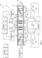
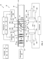
FIGS. 1-3 are schematic illustrations of a fluid system with a transfer valve operating in various modes of operation. -
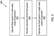
FIG. 4 is a flow diagram of a method for operating a fluid system. -
FIG. 1 illustrates a fluid system 10 for an aircraft. The aircraft may be an airplane, a helicopter, a drone (e.g., an unmanned aerial vehicle (UAV)) or any other manned or unmanned aerial vehicle or system. The fluid system 10 of the present disclosure, however, is not limited to aircraft applications. The fluid system 10, for example, may alternatively be configured for a land vehicle, an aquatic vehicle or any other mobile device or system. Moreover, the fluid system 10 may alternatively be configured for a stationary device or system. The fluid system 10 ofFIG. 1 includes amoveable component 12, afluid source 14, one or morefluid actuators valve system 18. - The
moveable component 12 ofFIG. 1 is a moveable component of the aircraft. Thismoveable component 12 may be a component of an airframe of the aircraft. Themoveable component 12, for example, may be configured as an aircraft control surface; e.g., a flap, a rudder, an elevator, a tab, a spoiler, an aileron, etc. Alternatively, themoveable component 12 may be a component of a propulsion system for the aircraft. Themoveable component 12, for example, may be configured as a translating sleeve for a thrust reverser, a variable nozzle structure, etc. - The
fluid source 14 ofFIG. 1 includes afluid reservoir 19 and afluid flow regulator 20. Thereservoir 19 is configured to store a quantity of fluid (e.g., hydraulic fluid, oil, etc.) before, during and/or after fluid system operation. Thereservoir 19, for example, may be configured as or otherwise include a tank, a cylinder, a pressure vessel, a bladder or any other type of fluid (e.g., liquid) storage container. Theflow regulator 20 is configured to direct a flow of the fluid from thereservoir 19 to the fluid actuators 16 through thevalve system 18. Theflow regulator 20, for example, may be configured as or otherwise include a pump. - Each fluid actuator 16 of
FIG. 1 is operatively coupled to and configured to pivot, translate, shift and/or otherwise move themoveable component 12. Each fluid actuator 16, for example, may be configured as a linear actuator such as a hydraulic piston. Eachfluid actuator FIG. 1 , in particular, includes acylinder piston arm moveable component 12. The cylinder 21 is coupled to a base structure; e.g., a stationary structure. With this arrangement, by increasing and/or decreasing fluid volume and/or pressure to one or both sides of the piston 22 within the internal cavity, each fluid actuator 16 may move themoveable component 12 by extending its actuator arm 23 out from the cylinder 21 or retracting its actuator arm 23 into the cylinder 21. The present disclosure, however, is not limited to such an exemplary type of fluid actuators. One or more of the fluid actuators 16, for example, may alternatively be configured as a fluid motor. Moreover, while the fluid actuators 16 ofFIG. 1 are associated with a common (the same)moveable component 12, it is contemplated the fluid actuators 16 may alternatively be operatively coupled to and configured to move discrete (e.g., similarly situated) moveable components. - Referring again to
FIG. 1 , thevalve system 18 is configured to control a flow of the fluid from thefluid source 14 to and/or from each of the fluid actuators 16. Thevalve system 18 ofFIG. 1 , for example, includes one ormore control valves controller 28. - Each control valve 24 may be configured as an electrohydraulic servo valve (EHSV). Each
control valve FIG. 1 includes one or more input and/or output (I/O)ports fluid source 14. For example, where thevalve system 18 is operated to extend the actuator arms 23, each control valve 24 directs fluid received from thefluid source 14 to its first I/O port 30, and each control valve 24 directs fluid received at its second I/O port 32 back to thefluid source 14. Here, the first I/O port 30 is configured as a feed port to thetransfer valve 26, and the second I/O port 32 is configured as a return port from thetransfer valve 26. In another example, where thevalve system 18 is operated to retract the actuator arms 23, each control valve 24 directs fluid received from thefluid source 14 to its second I/O port 32, and each control valve 24 directs fluid received at its first I/O port 30 back to thefluid source 14. Here, the second I/O port 32 is configured as a feed port to thetransfer valve 26, and the first I/O port 30 is configured as a return port from thetransfer valve 26. - The
transfer valve 26 includes avalve housing 34 and avalve body 36. Thetransfer valve 26 ofFIG. 1 also includes avalve actuator 38 operatively coupled to thevalve body 36. - The
valve housing 34 includes one or more firstcontrol valve ports 40 and 42 ("first valve ports"), one or more secondcontrol valve ports 44 and 46 ("second valve ports"), one or more firstfluid actuator ports 48 and 50 ("first actuator ports") and one or more secondfluid actuator ports 52 and 54 ("second actuator ports"). Thefirst valve ports O ports first control valve 24A. Thesecond valve ports O ports second control valve 24B. Thefirst actuator ports ports fluid actuator 16A. Thesecond actuator ports ports fluid actuator 16B. - The
valve body 36 ofFIG. 1 extends longitudinally along a centerline between afirst end 60 of thevalve body 36 and asecond end 62 of thevalve body 36. This centerline may be a longitudinal centerline of thevalve housing 34 and/or thevalve body 36. Thevalve body 36 includes a plurality of valve stations 64-66 arranged longitudinally along the centerline. Theintermediate station 64 is disposed longitudinally between the firstend valve station 65 and the secondend valve station 66. The firstend valve station 65 is disposed at (e.g., on, adjacent or proximate) the bodyfirst end 60. The secondend valve station 66 is disposed at the bodysecond end 62. These valve stations 64-66 are configured as discrete, interconnected longitudinally extending segments of thevalve body 36. - The
intermediate station 64 includes one or more firstfluid actuator passages 68 and 70 ("first actuator passages") and one or more secondfluid actuator passages 72 and 74 ("second actuator passages"). Eachfirst actuator passage first actuator passage first actuator passage first actuator passage second actuator passage second actuator passage second actuator passage second actuator passage intermediate station passages FIG. 1 are fluidly discrete from one another within thevalve body 36. - Each of the
intermediate station passages intermediate station passage intermediate station passage intermediate station passage first actuator passages second actuator passages first actuator passages second actuator passages intermediate station passages - The first
end valve station 65 includes one or more firstfluid actuator passages 76 and 78 ("first actuator passages") and one or more secondfluid actuator passages 80 and 82 ("second actuator passages"). Eachfirst actuator passage first actuator passage first actuator passage first actuator passage second actuator passage second actuator passage second actuator passage second actuator passage first actuator passage 76 and thesecond actuator passage 80 each extend to (or may be otherwise fluidly coupled with) the same respective valve side orifice. Similarly, thefirst actuator passage 78 and thesecond actuator passage 82 each extend to (or may be otherwise fluidly coupled with) the same respective valve side orifice. With this arrangement, the firstend station passages FIG. 1 are fluidly interconnected within thevalve body 36, and the firstend station passages FIG. 1 are fluidly interconnected within thevalve body 36. - Each of the first
end station passages end station passage end station passage end station passage first actuator passages second actuator passages first actuator passages second actuator passages end station passage intermediate station passage end station passage intermediate station passage intermediate station passages end station passages end station passages end station passages intermediate station passages end station passage intermediate station passage - The second
end valve station 66 includes one or more firstfluid actuator passages 84 and 86 ("first actuator passages") and one or more secondfluid actuator passages 88 and 90 ("second actuator passages"). Eachfirst actuator passage first actuator passage first actuator passage first actuator passage second actuator passage second actuator passage second actuator passage second actuator passage first actuator passage 84 and thesecond actuator passage 88 each extend to (or may be otherwise fluidly coupled with) the respective valve side orifice. Similarly, thefirst actuator passage 86 and thesecond actuator passage 90 each extend to (or may be otherwise fluidly coupled with) the respective valve side orifice. With this arrangement, the secondend station passages FIG. 1 are fluidly interconnected within thevalve body 36, and the secondend station passages FIG. 1 are fluidly interconnected within thevalve body 36. - Each of the second
end station passages end station passage end station passage end station passage first actuator passages second actuator passages first actuator passages second actuator passages end station passages end station passages end station passage intermediate station passage end station passage intermediate station passage intermediate station passages end station passages end station passages end station passages end station passages end station passages intermediate station passages end station passage intermediate station passage - The
valve body 36 ofFIG. 1 is disposed within an internal cavity of thevalve housing 34. Thevalve body 36 is configured for move (e.g., translate) within thevalve housing 34 and its internal cavity between a plurality of positions. These positions include an intermediate position (seeFIG. 1 ), a first end position (seeFIG. 2 ) and a second end position (seeFIG. 3 ). - When the
valve body 36 is in the intermediate position ofFIG. 1 , thetransfer valve 26 fluidly couples thefirst control valve 24A to the firstfluid actuator 16A, and thetransfer valve 26 fluidly couples thesecond control valve 24B to the secondfluid actuator 16B. Here, thefirst control valve 24A is fluidly decoupled from the secondfluid actuator 16B, and thesecond control valve 24B is fluidly decoupled from the firstfluid actuator 16A. More particularly, eachfirst actuator passage intermediate station 64 is disposed between, aligned with and fluidly coupled to a respective one of thefirst valve ports first actuator ports first control valve 24A may thereby control (e.g., regulate) fluid flow to and/or from and is dedicated to operation of the firstfluid actuator 16A. Eachsecond actuator passage intermediate station 64 is disposed between, aligned with and fluidly coupled to a respective one of thesecond valve ports second actuator ports second control valve 24B may thereby control (e.g., regulate) fluid flow to and/or from and is dedicated to operation of the secondfluid actuator 16B. - When the
valve body 36 is in the first end position ofFIG. 2 , thetransfer valve 26 fluidly couples thefirst control valve 24A to both the firstfluid actuator 16A and the secondfluid actuator 16B. Here, thesecond control valve 24B is fluidly decoupled from both the firstfluid actuator 16A and the secondfluid actuator 16B. More particularly, eachfirst actuator passage first end station 65 is disposed between, may be aligned with and is fluidly coupled to a respective one of thefirst valve ports first actuator ports second actuator passage first end station 65 is disposed between, may be aligned with and is fluidly coupled to a respective one of thefirst valve ports second actuator ports first control valve 24A may thereby control (e.g., regulate) fluid flow to and/or from and is dedicated to operation of both the firstfluid actuator 16A and the secondfluid actuator 16B. - When the
valve body 36 is in the second end position ofFIG. 3 , thetransfer valve 26 fluidly couples thesecond control valve 24B to both the firstfluid actuator 16A and the secondfluid actuator 16B. Here, thefirst control valve 24A is fluidly decoupled from both the firstfluid actuator 16A and the secondfluid actuator 16B. More particularly, eachfirst actuator passage second end station 66 is disposed between, may be aligned with and is fluidly coupled to a respective one of thesecond valve ports first actuator ports second actuator passage second end station 66 is disposed between, may be aligned with and is fluidly coupled to a respective one of thesecond valve ports second actuator ports second control valve 24B may thereby control (e.g., regulate) fluid flow to and/or from and is dedicated to operation of both the firstfluid actuator 16A and the secondfluid actuator 16B. - The
valve actuator 38 ofFIGS. 1-3 is configured to move thevalve body 36 within thevalve housing 34 between its various positions. Examples of thevalve actuator 38 include, but are not limited to, an electric solenoid and an electric motor. - The
controller 28 ofFIG. 1 is in signal communication (e.g., hardwired and/or wirelessly coupled) with thefirst control valve 24A, thesecond control valve 24B and thetransfer valve 26 and itsvalve actuator 38. Thecontroller 28 may be implemented with a combination of hardware and software. The hardware may include amemory 92 and at least oneprocessing device 94, whichprocessing device 94 may include one or more single-core and/or multi-core processors. The hardware may also or alternatively include analog and/or digital circuitry other than that described above. - The
memory 92 is configured to store software (e.g., program instructions) for execution by theprocessing device 94, which software execution may control and/or facilitate performance of one or more operations such as those described below. Thememory 92 may be a non-transitory computer readable medium. For example, thememory 92 may be configured as or include a volatile memory and/or a nonvolatile memory. Examples of a volatile memory may include a random access memory (RAM) such as a dynamic random access memory (DRAM), a static random access memory (SRAM), a synchronous dynamic random access memory (SDRAM), a video random access memory (VRAM), etc. Examples of a nonvolatile memory may include a read only memory (ROM), an electrically erasable programmable read-only memory (EEPROM), a computer hard drive, etc. - The fluid system 10 and its
transfer valve 26 may be operated in various modes of operation. For example, when both thefirst control valve 24A and thesecond control valve 24B are (e.g., fully) operational, the fluid system 10 and itstransfer valve 26 may operate in a multi-valve mode of operation; e.g., a normal operating mode. During this multi-valve mode of operation, the valve actuator positions thevalve body 36 at its intermediate position where eachcontrol valve fluid actuators control valves second control valve 24B is the non-operational control valve, the fluid system 10 and itstransfer valve 26 may operate in a first single valve mode of operation; e.g., a first backup and/or emergency operating mode. During this first single valve mode of operation, thevalve actuator 28 positions thevalve body 36 at its first end position where thefirst control valve 24A controls operation of both the firstfluid actuator 16A and the secondfluid actuator 16B. Thetransfer valve 26 may thereby operationally bypass the (e.g., non-operational)second control valve 24B during the first single valve mode of operation. Similarly, where thefirst control valve 24A is the non-operational control valve, the fluid system 10 and itstransfer valve 26 may operate in a second single valve mode of operation; e.g., a second backup and/or emergency operating mode. During this second single valve mode of operation, thevalve actuator 38 positions thevalve body 36 at its second end position where thesecond control valve 24B controls operation of both the firstfluid actuator 16A and the secondfluid actuator 16B. Thetransfer valve 26 may thereby operationally bypass the (e.g., non-operational)first control valve 24A during the second single valve mode of operation. - With the foregoing arrangement, the
multi-station transfer valve 26 may facilitate redundant control for each of the fluid actuators 16 without requiring inclusion of a separate back-up control valve for each fluid actuator 16. However, when operating in the multi-valve mode of operation, eachfluid actuator dedicated control valve multi-station transfer valve 26 of the present disclosure may thereby reduce cost, weight and/or spatial requirements of the fluid system 10. -
FIG. 4 is a flow diagram of amethod 400 for operating a fluid system. For ease of description, theoperating method 400 is described below with reference to the fluid system 10 ofFIGS. 1-3 . Themethod 400 of the present disclosure, however, is not limited to operating such an exemplary fluid system. - In
step 402, the fluid system 10 and itstransfer valve 26 are operated in the multi-valve mode of operation. Thecontroller 28 ofFIG. 1 , for example, may signal thevalve actuator 38 to position thevalve body 36 at its intermediate position. Thecontroller 28 may also signal thefirst control valve 24A and thesecond control valve 24B to selectively flow fluid to and/or from the firstfluid actuator 16A and the secondfluid actuator 16B to move (or hold a position of) themoveable component 12. - In
step 404, thecontroller 28 monitors operation of the fluid system 10. Thecontroller 28, for example, may receive one or more sensor signals indicative of the operation of the control valves 24 and/or one or more sensor signals indicative of the operation of the fluid actuators 16. Thecontroller 28 may then process data from the sensor signal(s) to determine if one or more of the control valves 24 is operating (e.g., opening, closing, holding its position, etc.) as expected. Where the control valves 24 are operating as expected, the fluid system 10 and itstransfer valve 26 may continue to operate in the multi-valve mode of operation. However, where one of thecontrol valves control valve operating method 400 may proceed to step 406. - In the
step 406, the fluid system 10 and itstransfer valve 26 are operated in one of the single valve modes of operation. For example, where it is determined thesecond control valve 24B is no longer operating as expected, thecontroller 28 may signal thevalve actuator 38 to move thevalve body 36 to its first end position ofFIG. 2 . The fluid system 10 may thereby operationally bypass the (e.g., non-operational)second control valve 24B and utilize the (e.g., operational)first control valve 24A to control operation of the firstfluid actuator 16A and the secondfluid actuator 16B. By contrast, where it is determined thefirst control valve 24A is no longer operating as expected, thecontroller 28 may signal thevalve actuator 38 to move thevalve body 36 to its second end position ofFIG. 3 . The fluid system 10 may thereby operationally bypass the (e.g., non-operational)first control valve 24A and utilize the (e.g., operational)second control valve 24B to control operation of the firstfluid actuator 16A and the secondfluid actuator 16B. - As described above, fluid flow through the
transfer valve 26 may be restricted when thevalve body 36 is in its intermediate position and operating in the multi-valve mode of operation. This restriction may limit an impact of fluid runaway if, for example, one of the control valves 24 malfunctions. However, fluid flow through thetransfer valve 26 may be unrestricted when thevalve body 36 is in its first and/or its second end position. Thetransfer valve 26 may thereby facilitate (e.g., full) operation of the firstfluid actuator 16A and the secondfluid actuator 16B even when regulated by the single control valve 24. - While various embodiments of the present disclosure have been described, it will be apparent to those of ordinary skill in the art that many more embodiments and implementations are possible within the scope of the disclosure. For example, the present disclosure as described herein includes several aspects and embodiments that include particular features. Although these features may be described individually, it is within the scope of the present disclosure that some or all of these features may be combined with any one of the aspects and remain within the scope of the disclosure. Accordingly, the present disclosure is not to be restricted except in light of the attached claims and their equivalents.
Claims (15)
- A fluid system (10), comprising:a first actuator (16A);a second actuator (16B); anda valve system (18) including a first control valve (24A), a second control valve (24B) and a transfer valve (26);during a first mode of operation, the transfer valve (26) configured to fluidly couple the first control valve (24A) to the first actuator (16A) and fluidly couple the second control valve (24B) to the second actuator (16B), and the transfer valve (26) further configured to fluidly decouple the first control valve (24A) from the second actuator (16B) and fluidly decouple the second control valve (24B) from the first actuator (16A); andduring a second mode of operation, the transfer valve (26) configured to fluidly couple the first control valve (24A) to the first actuator (16A) and the second actuator (16B), and the transfer valve (26) further configured to fluidly decouple the second control valve (24B) from the first actuator (16A) and the second actuator (16B).
- The fluid system (10) of claim 1, wherein, during a third mode of operation, the transfer valve (26) is configured to fluidly couple the second control valve (24B) to the first actuator (16A) and the second actuator (16B), and the transfer valve (26) is further configured to fluidly decouple the first control valve (24A) from the first actuator (16A) and the second actuator (16B).
- The fluid system (10) of claim 1 or 2, wherein at least one ofthe first actuator (16A) comprises a first piston actuator; orthe second actuator (16B) comprises a second piston actuator.
- The fluid system (10) of any of claims 1 to 3, wherein at least one of the first control valve (24A) comprises a first electrohydraulic servo valve; or
the second control valve (24B) comprises a second electrohydraulic servo valve. - The fluid system (10) of any preceding claim, whereina first station first passage (68, 70) in the transfer valve (26) has a minimum flow area, and the first station first passage (68, 70) fluidly couples the first control valve (24A) to the first actuator (16A) during the first mode of operation; anda second station first passage (76, 78) in the transfer valve (26) has a minimum flow area that is greater than the minimum flow area of the first station first passage (68, 70), and the second station first passage (76, 78) fluidly couples the first control valve (24A) to the first actuator (16A) during the second mode of operation.
- The fluid system (10) of claim 5, whereina first station second passage (72, 74) in the transfer valve (26) has a minimum flow area, and the first station second passage (72, 74) fluidly couples the second control valve (24B) to the second actuator (16B) during the first mode of operation; anda second station second passage (80, 82) in the transfer valve (26) has a minimum flow area that is greater than the minimum flow area of the first station second passage (72, 74), and the second station second passage (80, 82) fluidly couples the first control valve (24A) to the second actuator (16B) during the second mode of operation,optionally wherein at least one ofthe minimum flow area of the first station second passage (72, 74) is equal to the minimum flow area of the first station first passage (68, 70); orthe minimum flow area of the second station second passage (80, 82) is equal to the minimum flow area of the second station first passage (76, 78).
- The fluid system (10) of any preceding claim, whereinthe first actuator (16A) including a first inlet/outlet orifice (56A) and a second inlet/outlet orifice (58A); andthe transfer valve (26) is configured to discretely fluidly couple the first inlet/outlet orifice (56A) and the second inlet/outlet orifice (58A) to the first control valve (24A) during the first mode of operation and the second mode of operation.
- The fluid system (10) of any preceding claim, whereinthe second actuator (16B) including a first inlet/outlet orifice (56B) and a second inlet/outlet orifice (58B);the transfer valve (26) is configured to discretely fluidly couple the first inlet/outlet orifice (56B) and the second inlet/outlet orifice (58B) to the second control valve (24B) during the first mode of operation; andthe transfer valve (26) is configured to discretely fluidly couple the first inlet/outlet orifice (56B) and the second inlet/outlet orifice (58B) to the first control valve (24A) during the second mode of operation.
- The fluid system (10) of any preceding claim, further comprising:a fluid source (14);the valve system (18) fluidly coupling the fluid source (14) to the first actuator (16A) and the second actuator (16B).
- The fluid system (10) of any preceding claim, further comprising:an aircraft component (12);the first actuator (16A) and the second actuator (16B) operatively coupled to and configured to move the aircraft component (12).
- A fluid system (10), comprising:a first actuator (16A); anda valve system (18) including a first control valve (24A), a second control valve (24B) and a transfer valve (26);the transfer valve (26) including a first station first passage (68, 70) and a second station first passage (76, 78), wherein a minimum flow area of the first station first passage (68, 70) less than a minimum flow area of the second station first passage (76, 78);during a first mode of operation, the transfer valve (26) configured to fluidly couple the first control valve (24A) to the first actuator (16A) through the first station first passage (68, 70); andduring a second mode of operation, the transfer valve (26) configured to fluidly couple the second control valve (24B) to the first actuator (16A) through the second station first passage (76, 78);wherein the second control valve (24B) is fluidly decoupled from the first actuator (16A) during the first mode of operation, and the first control valve (24A) is fluidly decoupled from the first actuator (16A) during the second mode of operation.
- The fluid system (10) of claim 11, further comprising:a second actuator (16B);the transfer valve (26) further including a first station second passage (72, 74) and a second station second passage (80, 82), wherein a minimum flow area of the first station second passage (72, 74) less than a minimum flow area of the second station second passage (80, 82);during the first mode of operation, the transfer valve (26) configured to fluidly couple the second control valve (24B) to the second actuator (16B) through the first station second passage (72, 74); andduring the second mode of operation, the transfer valve (26) configured to fluidly couple the second control valve (24B) to the second actuator (16B) through the second station second passage (80, 82);wherein the first control valve (24A) is fluidly decoupled from the second actuator (16B) during the first mode of operation and the second mode of operation,optionally wherein, during a third mode of operation, the transfer valve (26) is configured tofluidly couple the first control valve (24A) to the first actuator (16A) and the second actuator (16B); andfluidly decouple the second control valve (24B) from the first actuator (16A) and the second actuator (16B).
- An operating method, comprising:during a first mode, fluidly coupling a first control valve (24A) to a first actuator (16A) through a transfer valve (26), and fluidly coupling a second control valve (24B) to a second actuator (16B) through the transfer valve (26); andduring a second mode, fluidly coupling the first control valve (24A) to the first actuator (16A) and the second actuator (16B) through the transfer valve (26), and fluidly decoupling the second control valve (24B) from the second actuator (16B).
- The operating method of claim 13, further comprising:selecting the first mode when the first control valve (24A) and the second control valve (24B) are each fully operational; andselecting the second mode when a fault is detected associated with the second control valve (24B).
- The operating method of claim 13 or 14, wherein:flow through the transfer valve (26) from the first control valve (24A) to the first actuator (16A) is restricted during the first mode and the flow through the transfer valve (26) from the first control valve (24A) to the first actuator (16A) is unrestricted during the second mode;the first control valve (24A) and the second control valve (24B) are each configured as an electrohydraulic servo valve; and/orthe method further comprises moving a component (12) of an aircraft using the first actuator (16A) and the second actuator (16B) during at least one of the first mode or the second mode.
Applications Claiming Priority (1)
| Application Number | Priority Date | Filing Date | Title |
|---|---|---|---|
| US18/237,272 US12345280B2 (en) | 2023-08-23 | 2023-08-23 | Fluid system with multi-mode transfer valve |
Publications (2)
| Publication Number | Publication Date |
|---|---|
| EP4524405A2 true EP4524405A2 (en) | 2025-03-19 |
| EP4524405A3 EP4524405A3 (en) | 2025-05-21 |
Family
ID=92538821
Family Applications (1)
| Application Number | Title | Priority Date | Filing Date |
|---|---|---|---|
| EP24196307.3A Pending EP4524405A3 (en) | 2023-08-23 | 2024-08-23 | Fluid system with multi-mode transfer valve |
Country Status (2)
| Country | Link |
|---|---|
| US (1) | US12345280B2 (en) |
| EP (1) | EP4524405A3 (en) |
Family Cites Families (16)
| Publication number | Priority date | Publication date | Assignee | Title |
|---|---|---|---|---|
| US3269676A (en) * | 1965-04-30 | 1966-08-30 | Sperry Rand Corp | Valve actuator apparatus |
| US3527143A (en) * | 1968-09-03 | 1970-09-08 | Automotive Prod Co Ltd | Control systems |
| US4688469A (en) * | 1985-10-21 | 1987-08-25 | Sundstrand Corporation | Fault detector for a triplexed mechanical or hydromechanical system |
| US4887214A (en) | 1987-10-27 | 1989-12-12 | The Boeing Company | Flight control system employing two dual controllers operating a dual actuator |
| FR2709110B1 (en) * | 1993-08-20 | 1995-11-10 | Lucas Air Equipement | Servo-control device of an aircraft flight control member. |
| US6637199B2 (en) * | 2002-01-28 | 2003-10-28 | Woodward Governor Co. | Pressure switching valve for multiple redundant electrohydraulic servo valve systems |
| JP3836422B2 (en) * | 2002-11-27 | 2006-10-25 | ナブテスコ株式会社 | Blade drive |
| GB2448914B (en) | 2007-05-03 | 2012-03-07 | Jcb Landpower Ltd | Vehicle |
| DE102008023628B4 (en) | 2008-05-15 | 2015-10-08 | Airbus Operations Gmbh | Actuation system for a hydraulically actuated vertical fin and test method for checking the integrity of a positioning system |
| US9657756B2 (en) | 2014-08-14 | 2017-05-23 | Hamilton Sundstrand Corporation | Actuator system |
| US10458557B2 (en) * | 2016-04-20 | 2019-10-29 | Sikorsky Aircraft Corporation | Hydraulic actuator force fight mitigation mechanism |
| US10538310B2 (en) * | 2016-06-29 | 2020-01-21 | Parker-Hannifin Corporation | Near synchronous distributed hydraulic motor driven actuation system |
| US10393285B2 (en) | 2017-10-02 | 2019-08-27 | United Technologies Corporation | Multi-actuation control system with pressure balancing plumbing |
| US11725647B2 (en) | 2021-05-18 | 2023-08-15 | Hamilton Sundstrand Corporation | On-demand dual variable displacement positive displacement pumping system |
| US12024306B2 (en) * | 2022-01-21 | 2024-07-02 | Hamilton Sundstrand Corporation | Actuator systems with shared redundancy |
| CN116221232B (en) | 2023-03-07 | 2026-01-27 | 北京航空航天大学 | Dual-redundancy electro-hydrostatic actuator with independent control and necrosis prevention functions |
-
2023
- 2023-08-23 US US18/237,272 patent/US12345280B2/en active Active
-
2024
- 2024-08-23 EP EP24196307.3A patent/EP4524405A3/en active Pending
Also Published As
| Publication number | Publication date |
|---|---|
| US20250067284A1 (en) | 2025-02-27 |
| EP4524405A3 (en) | 2025-05-21 |
| US12345280B2 (en) | 2025-07-01 |
Similar Documents
| Publication | Publication Date | Title |
|---|---|---|
| US3047257A (en) | Device for changing airfoil profile | |
| ES2312863T5 (en) | Improved system and method of flight control surface actuation | |
| US8418956B2 (en) | Aircraft actuator hydraulic system | |
| EP3222520A1 (en) | Local backup hydraulic actuator for aircraft control systems | |
| US8596575B2 (en) | Aircraft actuator | |
| EP2309156A1 (en) | Flow control valve | |
| CN111550468B (en) | Actuator control valve arrangement | |
| US11391384B2 (en) | Hydraulic actuator force fight mitigation mechanism | |
| US10920795B2 (en) | Bootstrap hydraulic reservoir | |
| EP3553325B1 (en) | Aircraft hydraulic system with a dual spool valve and methods of use | |
| US10570931B2 (en) | Aircraft hydraulic systems having shared components | |
| EP3561313B1 (en) | Aircraft hydraulic system with a dual spool valve and method of use | |
| US11390375B2 (en) | Control surface actuator assemblies, aircraft hydraulic systems including the same, and associated aircraft and methods | |
| US12345280B2 (en) | Fluid system with multi-mode transfer valve | |
| US4472998A (en) | Redundant control actuation system-concentric direct drive valve | |
| EP3786056B1 (en) | Methods and apparatus for mitigating aerodynamic flutter of aircraft wing flaps | |
| JP2002235859A (en) | Fail-freeze servo valve | |
| WO2024108739A1 (en) | Electrically-controlled hydraulic actuating system of aircraft | |
| CN100523472C (en) | Axial symmetric vector spray-pipe A9 action emergency resetting hydraulic system | |
| US8419345B2 (en) | Actuator | |
| US12480534B2 (en) | Valve and aircraft | |
| US12312070B2 (en) | Hydraulic energy retention | |
| CN110848198A (en) | Zero-oil-leakage energy conversion valve of double hydraulic system | |
| US20210253222A1 (en) | Hydraulic control systems and methods for components of an aircraft |
Legal Events
| Date | Code | Title | Description |
|---|---|---|---|
| PUAI | Public reference made under article 153(3) epc to a published international application that has entered the european phase |
Free format text: ORIGINAL CODE: 0009012 |
|
| STAA | Information on the status of an ep patent application or granted ep patent |
Free format text: STATUS: THE APPLICATION HAS BEEN PUBLISHED |
|
| AK | Designated contracting states |
Kind code of ref document: A2 Designated state(s): AL AT BE BG CH CY CZ DE DK EE ES FI FR GB GR HR HU IE IS IT LI LT LU LV MC ME MK MT NL NO PL PT RO RS SE SI SK SM TR |
|
| PUAL | Search report despatched |
Free format text: ORIGINAL CODE: 0009013 |
|
| AK | Designated contracting states |
Kind code of ref document: A3 Designated state(s): AL AT BE BG CH CY CZ DE DK EE ES FI FR GB GR HR HU IE IS IT LI LT LU LV MC ME MK MT NL NO PL PT RO RS SE SI SK SM TR |
|
| RIC1 | Information provided on ipc code assigned before grant |
Ipc: F15B 19/00 20060101ALN20250411BHEP Ipc: F15B 13/043 20060101ALN20250411BHEP Ipc: F15B 20/00 20060101ALI20250411BHEP Ipc: B64C 13/42 20060101ALI20250411BHEP Ipc: F15B 18/00 20060101AFI20250411BHEP |
|
| STAA | Information on the status of an ep patent application or granted ep patent |
Free format text: STATUS: REQUEST FOR EXAMINATION WAS MADE |
|
| 17P | Request for examination filed |
Effective date: 20251121 |