EP4524382A1 - Vented hydrogen fuel reservoir for aircraft engine - Google Patents
Vented hydrogen fuel reservoir for aircraft engine Download PDFInfo
- Publication number
- EP4524382A1 EP4524382A1 EP24200120.4A EP24200120A EP4524382A1 EP 4524382 A1 EP4524382 A1 EP 4524382A1 EP 24200120 A EP24200120 A EP 24200120A EP 4524382 A1 EP4524382 A1 EP 4524382A1
- Authority
- EP
- European Patent Office
- Prior art keywords
- plenum
- containment
- hydrogen
- purge
- cavity
- Prior art date
- Legal status (The legal status is an assumption and is not a legal conclusion. Google has not performed a legal analysis and makes no representation as to the accuracy of the status listed.)
- Pending
Links
Images

Classifications
-
- B—PERFORMING OPERATIONS; TRANSPORTING
- B64—AIRCRAFT; AVIATION; COSMONAUTICS
- B64D—EQUIPMENT FOR FITTING IN OR TO AIRCRAFT; FLIGHT SUITS; PARACHUTES; ARRANGEMENT OR MOUNTING OF POWER PLANTS OR PROPULSION TRANSMISSIONS IN AIRCRAFT
- B64D37/00—Arrangements in connection with fuel supply for power plant
- B64D37/02—Tanks
-
- B—PERFORMING OPERATIONS; TRANSPORTING
- B64—AIRCRAFT; AVIATION; COSMONAUTICS
- B64D—EQUIPMENT FOR FITTING IN OR TO AIRCRAFT; FLIGHT SUITS; PARACHUTES; ARRANGEMENT OR MOUNTING OF POWER PLANTS OR PROPULSION TRANSMISSIONS IN AIRCRAFT
- B64D37/00—Arrangements in connection with fuel supply for power plant
- B64D37/30—Fuel systems for specific fuels
-
- F—MECHANICAL ENGINEERING; LIGHTING; HEATING; WEAPONS; BLASTING
- F02—COMBUSTION ENGINES; HOT-GAS OR COMBUSTION-PRODUCT ENGINE PLANTS
- F02C—GAS-TURBINE PLANTS; AIR INTAKES FOR JET-PROPULSION PLANTS; CONTROLLING FUEL SUPPLY IN AIR-BREATHING JET-PROPULSION PLANTS
- F02C3/00—Gas-turbine plants characterised by the use of combustion products as the working fluid
- F02C3/20—Gas-turbine plants characterised by the use of combustion products as the working fluid using a special fuel, oxidant, or dilution fluid to generate the combustion products
- F02C3/22—Gas-turbine plants characterised by the use of combustion products as the working fluid using a special fuel, oxidant, or dilution fluid to generate the combustion products the fuel or oxidant being gaseous at standard temperature and pressure
-
- F—MECHANICAL ENGINEERING; LIGHTING; HEATING; WEAPONS; BLASTING
- F02—COMBUSTION ENGINES; HOT-GAS OR COMBUSTION-PRODUCT ENGINE PLANTS
- F02C—GAS-TURBINE PLANTS; AIR INTAKES FOR JET-PROPULSION PLANTS; CONTROLLING FUEL SUPPLY IN AIR-BREATHING JET-PROPULSION PLANTS
- F02C7/00—Features, components parts, details or accessories, not provided for in, or of interest apart form groups F02C1/00 - F02C6/00; Air intakes for jet-propulsion plants
- F02C7/22—Fuel supply systems
-
- F—MECHANICAL ENGINEERING; LIGHTING; HEATING; WEAPONS; BLASTING
- F17—STORING OR DISTRIBUTING GASES OR LIQUIDS
- F17C—VESSELS FOR CONTAINING OR STORING COMPRESSED, LIQUEFIED OR SOLIDIFIED GASES; FIXED-CAPACITY GAS-HOLDERS; FILLING VESSELS WITH, OR DISCHARGING FROM VESSELS, COMPRESSED, LIQUEFIED, OR SOLIDIFIED GASES
- F17C13/00—Details of vessels or of the filling or discharging of vessels
- F17C13/12—Arrangements or mounting of devices for preventing or minimising the effect of explosion ; Other safety measures
- F17C13/123—Arrangements or mounting of devices for preventing or minimising the effect of explosion ; Other safety measures for gas bottles, cylinders or reservoirs for tank vehicles or for railway tank wagons
-
- F—MECHANICAL ENGINEERING; LIGHTING; HEATING; WEAPONS; BLASTING
- F17—STORING OR DISTRIBUTING GASES OR LIQUIDS
- F17C—VESSELS FOR CONTAINING OR STORING COMPRESSED, LIQUEFIED OR SOLIDIFIED GASES; FIXED-CAPACITY GAS-HOLDERS; FILLING VESSELS WITH, OR DISCHARGING FROM VESSELS, COMPRESSED, LIQUEFIED, OR SOLIDIFIED GASES
- F17C7/00—Methods or apparatus for discharging liquefied, solidified, or compressed gases from pressure vessels, not covered by another subclass
-
- F—MECHANICAL ENGINEERING; LIGHTING; HEATING; WEAPONS; BLASTING
- F05—INDEXING SCHEMES RELATING TO ENGINES OR PUMPS IN VARIOUS SUBCLASSES OF CLASSES F01-F04
- F05D—INDEXING SCHEME FOR ASPECTS RELATING TO NON-POSITIVE-DISPLACEMENT MACHINES OR ENGINES, GAS-TURBINES OR JET-PROPULSION PLANTS
- F05D2260/00—Function
- F05D2260/60—Fluid transfer
- F05D2260/605—Venting into the ambient atmosphere or the like
-
- F—MECHANICAL ENGINEERING; LIGHTING; HEATING; WEAPONS; BLASTING
- F05—INDEXING SCHEMES RELATING TO ENGINES OR PUMPS IN VARIOUS SUBCLASSES OF CLASSES F01-F04
- F05D—INDEXING SCHEME FOR ASPECTS RELATING TO NON-POSITIVE-DISPLACEMENT MACHINES OR ENGINES, GAS-TURBINES OR JET-PROPULSION PLANTS
- F05D2260/00—Function
- F05D2260/60—Fluid transfer
- F05D2260/608—Aeration, ventilation, dehumidification or moisture removal of closed spaces
-
- F—MECHANICAL ENGINEERING; LIGHTING; HEATING; WEAPONS; BLASTING
- F17—STORING OR DISTRIBUTING GASES OR LIQUIDS
- F17C—VESSELS FOR CONTAINING OR STORING COMPRESSED, LIQUEFIED OR SOLIDIFIED GASES; FIXED-CAPACITY GAS-HOLDERS; FILLING VESSELS WITH, OR DISCHARGING FROM VESSELS, COMPRESSED, LIQUEFIED, OR SOLIDIFIED GASES
- F17C2201/00—Vessel construction, in particular geometry, arrangement or size
- F17C2201/05—Size
- F17C2201/054—Size medium (>1 m3)
-
- F—MECHANICAL ENGINEERING; LIGHTING; HEATING; WEAPONS; BLASTING
- F17—STORING OR DISTRIBUTING GASES OR LIQUIDS
- F17C—VESSELS FOR CONTAINING OR STORING COMPRESSED, LIQUEFIED OR SOLIDIFIED GASES; FIXED-CAPACITY GAS-HOLDERS; FILLING VESSELS WITH, OR DISCHARGING FROM VESSELS, COMPRESSED, LIQUEFIED, OR SOLIDIFIED GASES
- F17C2205/00—Vessel construction, in particular mounting arrangements, attachments or identifications means
- F17C2205/01—Mounting arrangements
- F17C2205/0103—Exterior arrangements
- F17C2205/0111—Boxes
-
- F—MECHANICAL ENGINEERING; LIGHTING; HEATING; WEAPONS; BLASTING
- F17—STORING OR DISTRIBUTING GASES OR LIQUIDS
- F17C—VESSELS FOR CONTAINING OR STORING COMPRESSED, LIQUEFIED OR SOLIDIFIED GASES; FIXED-CAPACITY GAS-HOLDERS; FILLING VESSELS WITH, OR DISCHARGING FROM VESSELS, COMPRESSED, LIQUEFIED, OR SOLIDIFIED GASES
- F17C2205/00—Vessel construction, in particular mounting arrangements, attachments or identifications means
- F17C2205/03—Fluid connections, filters, valves, closure means or other attachments
- F17C2205/0302—Fittings, valves, filters, or components in connection with the gas storage device
- F17C2205/0323—Valves
-
- F—MECHANICAL ENGINEERING; LIGHTING; HEATING; WEAPONS; BLASTING
- F17—STORING OR DISTRIBUTING GASES OR LIQUIDS
- F17C—VESSELS FOR CONTAINING OR STORING COMPRESSED, LIQUEFIED OR SOLIDIFIED GASES; FIXED-CAPACITY GAS-HOLDERS; FILLING VESSELS WITH, OR DISCHARGING FROM VESSELS, COMPRESSED, LIQUEFIED, OR SOLIDIFIED GASES
- F17C2221/00—Handled fluid, in particular type of fluid
- F17C2221/01—Pure fluids
- F17C2221/012—Hydrogen
-
- F—MECHANICAL ENGINEERING; LIGHTING; HEATING; WEAPONS; BLASTING
- F17—STORING OR DISTRIBUTING GASES OR LIQUIDS
- F17C—VESSELS FOR CONTAINING OR STORING COMPRESSED, LIQUEFIED OR SOLIDIFIED GASES; FIXED-CAPACITY GAS-HOLDERS; FILLING VESSELS WITH, OR DISCHARGING FROM VESSELS, COMPRESSED, LIQUEFIED, OR SOLIDIFIED GASES
- F17C2223/00—Handled fluid before transfer, i.e. state of fluid when stored in the vessel or before transfer from the vessel
- F17C2223/01—Handled fluid before transfer, i.e. state of fluid when stored in the vessel or before transfer from the vessel characterised by the phase
- F17C2223/0107—Single phase
- F17C2223/0123—Single phase gaseous, e.g. CNG, GNC
-
- F—MECHANICAL ENGINEERING; LIGHTING; HEATING; WEAPONS; BLASTING
- F17—STORING OR DISTRIBUTING GASES OR LIQUIDS
- F17C—VESSELS FOR CONTAINING OR STORING COMPRESSED, LIQUEFIED OR SOLIDIFIED GASES; FIXED-CAPACITY GAS-HOLDERS; FILLING VESSELS WITH, OR DISCHARGING FROM VESSELS, COMPRESSED, LIQUEFIED, OR SOLIDIFIED GASES
- F17C2223/00—Handled fluid before transfer, i.e. state of fluid when stored in the vessel or before transfer from the vessel
- F17C2223/03—Handled fluid before transfer, i.e. state of fluid when stored in the vessel or before transfer from the vessel characterised by the pressure level
- F17C2223/036—Very high pressure (>80 bar)
-
- F—MECHANICAL ENGINEERING; LIGHTING; HEATING; WEAPONS; BLASTING
- F17—STORING OR DISTRIBUTING GASES OR LIQUIDS
- F17C—VESSELS FOR CONTAINING OR STORING COMPRESSED, LIQUEFIED OR SOLIDIFIED GASES; FIXED-CAPACITY GAS-HOLDERS; FILLING VESSELS WITH, OR DISCHARGING FROM VESSELS, COMPRESSED, LIQUEFIED, OR SOLIDIFIED GASES
- F17C2227/00—Transfer of fluids, i.e. method or means for transferring the fluid; Heat exchange with the fluid
- F17C2227/01—Propulsion of the fluid
- F17C2227/0128—Propulsion of the fluid with pumps or compressors
- F17C2227/0135—Pumps
-
- F—MECHANICAL ENGINEERING; LIGHTING; HEATING; WEAPONS; BLASTING
- F17—STORING OR DISTRIBUTING GASES OR LIQUIDS
- F17C—VESSELS FOR CONTAINING OR STORING COMPRESSED, LIQUEFIED OR SOLIDIFIED GASES; FIXED-CAPACITY GAS-HOLDERS; FILLING VESSELS WITH, OR DISCHARGING FROM VESSELS, COMPRESSED, LIQUEFIED, OR SOLIDIFIED GASES
- F17C2227/00—Transfer of fluids, i.e. method or means for transferring the fluid; Heat exchange with the fluid
- F17C2227/04—Methods for emptying or filling
- F17C2227/044—Methods for emptying or filling by purging
-
- F—MECHANICAL ENGINEERING; LIGHTING; HEATING; WEAPONS; BLASTING
- F17—STORING OR DISTRIBUTING GASES OR LIQUIDS
- F17C—VESSELS FOR CONTAINING OR STORING COMPRESSED, LIQUEFIED OR SOLIDIFIED GASES; FIXED-CAPACITY GAS-HOLDERS; FILLING VESSELS WITH, OR DISCHARGING FROM VESSELS, COMPRESSED, LIQUEFIED, OR SOLIDIFIED GASES
- F17C2260/00—Purposes of gas storage and gas handling
- F17C2260/03—Dealing with losses
- F17C2260/035—Dealing with losses of fluid
- F17C2260/037—Handling leaked fluid
-
- F—MECHANICAL ENGINEERING; LIGHTING; HEATING; WEAPONS; BLASTING
- F17—STORING OR DISTRIBUTING GASES OR LIQUIDS
- F17C—VESSELS FOR CONTAINING OR STORING COMPRESSED, LIQUEFIED OR SOLIDIFIED GASES; FIXED-CAPACITY GAS-HOLDERS; FILLING VESSELS WITH, OR DISCHARGING FROM VESSELS, COMPRESSED, LIQUEFIED, OR SOLIDIFIED GASES
- F17C2260/00—Purposes of gas storage and gas handling
- F17C2260/03—Dealing with losses
- F17C2260/035—Dealing with losses of fluid
- F17C2260/038—Detecting leaked fluid
-
- F—MECHANICAL ENGINEERING; LIGHTING; HEATING; WEAPONS; BLASTING
- F17—STORING OR DISTRIBUTING GASES OR LIQUIDS
- F17C—VESSELS FOR CONTAINING OR STORING COMPRESSED, LIQUEFIED OR SOLIDIFIED GASES; FIXED-CAPACITY GAS-HOLDERS; FILLING VESSELS WITH, OR DISCHARGING FROM VESSELS, COMPRESSED, LIQUEFIED, OR SOLIDIFIED GASES
- F17C2260/00—Purposes of gas storage and gas handling
- F17C2260/04—Reducing risks and environmental impact
- F17C2260/042—Reducing risk of explosion
-
- F—MECHANICAL ENGINEERING; LIGHTING; HEATING; WEAPONS; BLASTING
- F17—STORING OR DISTRIBUTING GASES OR LIQUIDS
- F17C—VESSELS FOR CONTAINING OR STORING COMPRESSED, LIQUEFIED OR SOLIDIFIED GASES; FIXED-CAPACITY GAS-HOLDERS; FILLING VESSELS WITH, OR DISCHARGING FROM VESSELS, COMPRESSED, LIQUEFIED, OR SOLIDIFIED GASES
- F17C2265/00—Effects achieved by gas storage or gas handling
- F17C2265/06—Fluid distribution
- F17C2265/066—Fluid distribution for feeding engines for propulsion
-
- F—MECHANICAL ENGINEERING; LIGHTING; HEATING; WEAPONS; BLASTING
- F17—STORING OR DISTRIBUTING GASES OR LIQUIDS
- F17C—VESSELS FOR CONTAINING OR STORING COMPRESSED, LIQUEFIED OR SOLIDIFIED GASES; FIXED-CAPACITY GAS-HOLDERS; FILLING VESSELS WITH, OR DISCHARGING FROM VESSELS, COMPRESSED, LIQUEFIED, OR SOLIDIFIED GASES
- F17C2270/00—Applications
- F17C2270/01—Applications for fluid transport or storage
- F17C2270/0186—Applications for fluid transport or storage in the air or in space
- F17C2270/0189—Planes
Definitions
- This disclosure relates generally to an aircraft and, more particularly, to a fuel delivery system for an aircraft engine.
- an assembly for an aircraft.
- This aircraft assembly includes a hydrogen containment vessel, a hydrogen storage vessel, a hydrogen supply channel, a cavity purge channel and a plenum purge channel.
- the hydrogen containment vessel includes a containment vessel wall.
- the hydrogen storage vessel includes a storage vessel wall and a storage cavity.
- the hydrogen storage vessel is disposed within the hydrogen containment vessel.
- a containment plenum is disposed between the storage vessel wall and the containment vessel wall.
- the hydrogen supply channel is fluidly coupled with the storage cavity.
- the cavity purge channel is fluidly coupled with the storage cavity.
- the plenum purge channel is fluidly coupled with the containment plenum.
- This aircraft assembly includes a hydrogen containment vessel, a hydrogen storage vessel, a hydrogen supply circuit, a plenum purge circuit and a flushing circuit.
- the hydrogen containment vessel includes a containment vessel wall.
- the hydrogen storage vessel includes a storage vessel wall and a storage cavity.
- the hydrogen storage vessel is disposed within the hydrogen containment vessel.
- a containment plenum extends between the storage vessel wall and the containment vessel wall.
- the hydrogen supply circuit is fluidly coupled with the storage cavity.
- the plenum purge circuit is fluidly coupled with the containment plenum.
- the flushing circuit is fluidly coupled with the containment plenum.
- the flushing circuit is configured to direct fluid into the containment plenum to flush out hydrogen fuel, which has leaked from the hydrogen storage vessel into the containment plenum, through the plenum purge circuit.
- the air may be directed into the containment plenum using an electric fan.
- the aircraft assembly may also include a cavity purge circuit fluidly coupled with the storage cavity.
- the cavity purge circuit may be configured to selectively purge the hydrogen fuel out of the hydrogen storage vessel.
- the aircraft assembly may also include an aircraft engine, which aircraft engine may include a fuel injector.
- the fuel injector may be fluidly coupled with the storage cavity through the hydrogen supply channel.
- the hydrogen supply channel may project through the containment vessel wall.
- the cavity purge channel may project through the containment vessel wall.
- the aircraft assembly may also include a cavity purge circuit configured to selectively fluidly couple the storage cavity to an external environment.
- the cavity purge circuit may include the cavity purge channel.
- the plenum purge circuit may also include a plenum purge valve fluidly coupled to the containment plenum by the plenum purge channel.
- the aircraft assembly may also include a plenum purge circuit and a cavity purge circuit.
- the plenum purge circuit may be configured to purge leaked hydrogen fuel from the containment plenum.
- the plenum purge circuit may include the plenum purge channel.
- the cavity purge circuit may be configured to purge stored hydrogen fuel from the storage cavity when a parameter of the leaked hydrogen fuel is greater than a threshold, the cavity purge circuit comprising the cavity purge channel.
- the flushing circuit may include an air pump.
- the flushing circuit may include a valve.
- the aircraft assembly may also include an air source selectively fluidly coupled to the containment plenum through the flushing circuit.
- the aircraft assembly may also include an aircraft engine, which aircraft engine may include a fuel injector and a flowpath.
- the fuel injector may be fluidly coupled with the storage cavity through the hydrogen supply channel.
- the air source may be or otherwise include a bleed from the flowpath.
- the present disclosure may include any one or more of the individual features disclosed above and/or below alone or in any combination thereof.
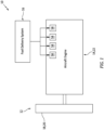
- FIG. 1 illustrates a system 10 for an aircraft.
- the aircraft may be an airplane, a helicopter, a drone (e.g., an unmanned aerial vehicle (UAV)) or any other manned or unmanned aerial vehicle or system.
- the aircraft system 10 may be configured as, or otherwise included as part of, a propulsion system for the aircraft.
- the aircraft system 10 may also or alternatively be configured as, or otherwise included as part of, an electrical power system for the aircraft.
- the aircraft system 10 of FIG. 1 includes a mechanical load 12 and an aircraft engine 14 configured to power operation of the mechanical load 12.
- the aircraft system 10 also include a fuel delivery system 16 for the aircraft engine 14.
- the mechanical load 12 may be configured as or otherwise include a rotor 18 mechanically driven and/or otherwise powered by the aircraft engine 14.
- This driven rotor 18 may be a bladed propulsor rotor 20 (e.g., an air mover) where the aircraft system 10 is (or is part of) the aircraft propulsion system.
- the propulsor rotor 20 includes a plurality of rotor blades arranged circumferentially around and connected to at least (or only) one rotor base (e.g., a disk or a hub).
- the propulsor rotor 20 may be an open (e.g., un-ducted) propulsor rotor or a ducted propulsor rotor.
- the open propulsor rotor examples include a propeller rotor for a turboprop propulsion system, a rotorcraft rotor (e.g., a main helicopter rotor) for a turboshaft propulsion system, a propfan rotor for a propfan propulsion system, and a pusher fan rotor for a pusher fan propulsion system.
- An example of the ducted propulsor rotor is a fan rotor for a turbofan propulsion system.
- the driven rotor 18 may alternatively be a generator rotor of an electric power generator where the aircraft system 10 is (or is part of) the aircraft power system; e.g., an auxiliary power unit (APU) for the aircraft.
- APU auxiliary power unit
- the aircraft engine 14 is configured as an internal combustion (IC) engine.
- the aircraft engine 14 of FIG. 2 for example, is configured as a gas turbine engine 22.
- the present disclosure is not limited to such an exemplary aircraft engine configuration.
- the aircraft engine 14, for example, may alternatively be configured as or otherwise include a rotary engine (e.g., a Wankel cycle engine), a reciprocating piston engine (e.g., an inline (I) engine, a V-engine or a W-engine), or the like.
- a rotary engine e.g., a Wankel cycle engine
- a reciprocating piston engine e.g., an inline (I) engine, a V-engine or a W-engine
- a core 24 of the gas turbine engine 22 of FIG. 2 extends axially along an axis 26 between an upstream, forward end of the engine core 24 and a downstream, aft end of the engine core 24.
- This axis 26 may be a centerline axis of the gas turbine engine 22 and/or its engine core 24.
- the axis 26 may also or alternatively be a rotational axis of one or more rotating assemblies (e.g., 28 and 30) of the gas turbine engine 22 and its engine core 24.
- the engine core 24 of FIG. 2 includes a compressor section 32, a combustor section 33, a turbine section 34 and a core flowpath 36.
- the core flowpath 36 extends sequentially through the compressor section 32, the combustor section 33, the HPT section 34A and the LPT section 34B from an airflow inlet 38 into the core flowpath 36 to a combustion products exhaust 40 from the core flowpath 36.
- the core inlet 38 may be disposed at (e.g., on, adjacent or proximate) the forward end of the engine core 24, and the core exhaust 40 may be disposed at the aft end of the engine core 24.
- Each of the engine sections 32, 34A and 34B includes one or more respective bladed rotors 42-44.
- Each of these engine rotors 42-44 includes a plurality of rotor blades (e.g., airfoils, vanes, etc.) arranged circumferentially around and connected to at least (or only) one rotor base (e.g., a disk, a hub, etc.).
- the rotor blades for example, may be formed integral with or mechanically fastened, welded, brazed and/or otherwise attached to the respective rotor base(s).
- the compressor rotors 42 are coupled to and rotatable with the HPT rotor 43.
- the compressor rotors 42 of FIG. 2 are connected to the HPT rotor 43 by a high speed shaft 46. At least (or only) the compressor rotors 42, the HPT rotor 43 and the high speed shaft 46 collectively form the high speed rotating assembly 28; e.g., a high speed spool.
- the LPT rotor 44 is connected to a low speed shaft 48. At least (or only) the LPT rotor 44 and the low speed shaft 48 collectively form the low speed rotating assembly 30.
- This low speed rotating assembly 30 is further coupled to the driven rotor 18 (e.g., the propulsor rotor 20) through a drivetrain 50.
- the drivetrain 50 may be configured as a geared drivetrain, where a geartrain 52 (e.g., a transmission, a speed change device, an epicyclic geartrain, etc.) is disposed between and operatively couples the driven rotor 18 to the low speed rotating assembly 30 and its LPT rotor 44.
- the driven rotor 18 may rotate at a different (e.g., slower) rotational velocity than the low speed rotating assembly 30 and its LPT rotor 44.
- the drivetrain 50 may alternatively be configured as a direct drive drivetrain, where the geartrain 52 is omitted.
- each of the rotating assemblies 28 and 30 and its members may be rotatable about the axis 26.
- air may be directed across the driven rotor 18 (e.g., the propulsor rotor 20) and into the engine core 24 through the core inlet 38.
- This air entering the core flowpath 36 may be referred to as core air.
- the core air is compressed by the compressor rotors 42 and directed into a combustion chamber 54 (e.g., an annular combustion chamber) within a combustor 56 (e.g., an annular combustor) of the combustor section 33.
- Fuel is injected into the combustion chamber 54 by one or more fuel injectors 58 and mixed with the compressed core air to provide a fuel-air mixture.
- This fuel-air mixture is ignited and combustion products thereof flow through and sequentially cause the HPT rotor 43 and the LPT rotor 44 to rotate.
- the rotation of the HPT rotor 43 drives rotation of the compressor rotors 42 and, thus, the compression of the air received from the core inlet 38.
- the rotation of the LPT rotor 44 drives rotation of the driven rotor 18.
- the driven rotor 18 is configured as the propulsor rotor 20
- the rotation of that propulsor rotor 20 may propel additional air (e.g., outside air, bypass air, etc.) outside of the engine core 24 to provide aircraft thrust and/or lift.
- the driven rotor 18 is configured as the generator rotor, the rotation of that generator rotor may facilitate generation of electricity.
- the fuel delivery system 16 is configured to deliver the fuel to the combustor section 33 and its combustor 56 for combustion.
- the fuel delivery system 16 of FIG. 3 includes a fuel source 60, a fuel supply circuit 62 and the one or more fuel injectors 58.
- the fuel source 60 of FIG. 3 includes a fuel reservoir 64 and a fuel flow regulator 66; e.g., a valve and/or a pump.
- the fuel reservoir 64 is configured to store the fuel before, during and/or after turbine engine operation.
- the fuel flow regulator 66 is configured to direct and/or meter a flow of the fuel from the fuel reservoir 64 to the fuel injectors 58 through the fuel supply circuit 62.
- the fuel injectors 58 may be arranged circumferentially about the axis 26 in an array. Each fuel injector 58 is configured to direct the fuel received from the fuel source 60 into the combustion chamber 54 for mixing with the compressed core air to provide the fuel-air mixture.
- the aircraft engine 14 of the present disclosure is configured as a non-hydrocarbon engine / a hydrocarbon free engine.
- the aircraft engine 14, more particularly, is configured as a hydrogen fueled engine.
- the fuel injected into the combustion chamber 54 by the fuel injectors 58 is (or substantially includes) hydrogen (H 2 ) fuel; e.g., H 2 gas.
- Hydrogen fuel is readily flammable / combustible when in the presence of oxygen and an ignition source; e.g., a flame, a spark, a relatively hot object, etc. Special care therefore is provided for storing the hydrogen fuel onboard the aircraft.
- the fuel reservoir 64 of FIG. 4 for example, is a vented double walled hydrogen fuel reservoir. More particularly, the fuel reservoir 64 of FIG. 4 includes a hydrogen storage vessel 68 and a hydrogen containment vessel 70.
- the hydrogen storage vessel 68 may form a primary fuel storage container for the aircraft engine 14 onboard the aircraft.
- the hydrogen storage vessel 68 may be configured as a tank, a cylinder, a pressure vessel, a bladder or any other type of fuel storage container.
- the hydrogen storage vessel 68 of FIG. 4 for example, has a storage vessel wall 72 (e.g., a sidewall) which forms an outer peripheral boundary of an enclosed hydrogen storage cavity 74 internal to the hydrogen storage vessel 68.
- the hydrogen storage vessel 68 and its storage vessel wall 72 may be constructed from metal, a fiber-reinforced composite material or another suitable material.
- the hydrogen containment vessel 70 may form a fuel containment boundary for (e.g., an outer shell around) the hydrogen storage vessel 68.
- the hydrogen containment vessel 70 may be configured as a tank, a cylinder, a pressure vessel, a bladder or any other type of fuel containment container.
- the hydrogen containment vessel 70 of FIG. 4 for example, has a containment vessel wall 76 (e.g., a sidewall) which forms an outer peripheral boundary of an enclosed hydrogen containment cavity 78 internal to the hydrogen containment vessel 70.
- the hydrogen containment vessel 70 and its containment vessel wall 76 may be constructed from metal, a fiber-reinforced composite material or another suitable material.
- the material forming the hydrogen containment vessel 70 and its containment vessel wall 76 may be the same or different than the material forming the hydrogen storage vessel 68 and its storage vessel wall 72.
- the containment vessel wall 76 may have a reduced pressure capability and/or strength compared to the storage vessel wall 72 since the hydrogen containment vessel 70 is provided to contain hydrogen fuel leaked out from the hydrogen storage vessel 68 whereas the hydrogen storage vessel 68 is provided to hold a bulk of the hydrogen fuel.
- the containment vessel wall 76 may have a thickness that is less than (e.g., up to five times (5x) less than) a thickness of the storage vessel wall 72.
- the present disclosure is not limited to such an arrangement. It is contemplated, for example, the hydrogen storage vessel 68 and the hydrogen containment vessel 70 may alternatively have similar or the same structural properties.
- the hydrogen storage vessel 68 of FIG. 4 is disposed within the hydrogen containment vessel 70 and its hydrogen containment cavity 78.
- the fuel supply circuit 62 (a hydrogen supply circuit) fluidly couples the hydrogen storage cavity 74 to the fuel injectors 58 across the containment vessel wall 76.
- the fuel supply circuit 62 of FIG. 4 for example, includes a fuel supply channel 80 (a hydrogen supply channel) which projects out from the storage cavity 74 and through the containment vessel wall 76.
- the storage vessel wall 72 of FIG. 4 is spaced inward from the containment vessel wall 76.
- the fuel reservoir 64 has a containment plenum 82 about (e.g., substantially or completely surrounding) the hydrogen storage vessel 68 and between the storage vessel wall 72 and the containment vessel wall 76.
- the storage vessel wall 72 forms an inner peripheral boundary of the containment plenum 82.
- the containment vessel wall 76 forms an outer peripheral boundary of the containment plenum 82.
- the hydrogen containment vessel 70 and its containment vessel wall 76 may thereby contain (e.g., any) hydrogen fuel, which may leak out from the hydrogen storage vessel 68 (and/or fittings connected to the hydrogen storage vessel 68) during fuel delivery system operation, within the containment plenum 82.
- the leaked hydrogen fuel may be purged / vented from the hydrogen containment vessel 70 and the containment plenum 82 using a plenum purge circuit 84.
- the plenum purge circuit 84 of FIG. 4 includes a plenum purge channel 86 and a plenum purge valve 88 which is fluidly coupled to the containment plenum 82 along the plenum purge channel 86.
- This plenum purge circuit 84 is configured to selectively fluidly couple the containment plenum 82 to an environment 90 external to the fuel delivery system 16 and, for example, external to the aircraft.
- the plenum purge circuit 84 may thereby discharge the leaked hydrogen fuel relatively far away from potential sources of ignition. However, when there is relatively little or no leaked hydrogen fuel, the plenum purge valve 88 may close to fluidly decouple the containment plenum 82 from the outlet 92 / the external environment 90.
- the fuel reservoir 64 may be configured with an optional plenum flushing circuit 94.
- the flushing circuit 94 of FIG. 4 includes a flushing channel 96 and a flushing valve 98 which is fluidly coupled to the containment plenum 82 along the flushing channel 96.
- This flushing circuit 94 is configured to selectively fluidly couple the containment plenum 82 to a flushing fluid source such as an air source 100.
- This air source 100 may be configured as the external environment 90.
- the flushing circuit 94 may include an air pump 102 (e.g., an electric fan / blower) which directs ambient air from the external environment 90, through the flushing channel 96, into the containment plenum 82.
- the air source 100 may be configured as a bleed from a flowpath of the aircraft engine 14; e.g., a core flowpath bleed, a bypass flowpath bleed, etc.
- forced air is directed into the containment plenum 82 to flush out the leaked hydrogen fuel from the containment plenum 82 through the plenum purge circuit 84.
- the air directed into the containment plenum 82 may also dilute the leaked hydrogen fuel.
- the flushing valve 98 may close to fluidly decouple the air source 100 from the containment plenum 82.
- a cavity purge circuit 104 may thereby be provided to facilitate purging the storage cavity 74 of some or all of its stored hydrogen fuel.
- the cavity purge circuit 104 of FIG. 4 includes a cavity purge channel 106 and a cavity purge valve 108 which is fluidly coupled to the storage cavity 74 along the cavity purge channel 106.
- This cavity purge circuit 104 is configured to selectively fluidly couple the storage cavity 74 to the external environment 90.
- the cavity purge circuit 104 of FIG. 4 and its cavity purge channel 106 project out from the hydrogen containment vessel 70 and its storage vessel wall 72, through the containment vessel wall 76, to an outlet 110 to ambient.
- the cavity purge circuit 104 may thereby discharge the stored hydrogen fuel relatively far away from potential sources of ignition as well as prevent overloading the hydrogen containment vessel 70 and/or the plenum purge circuit 84.
- the cavity purge valve 108 may close to fluidly decouple the storage cavity 74 from the outlet 110/ the external environment 90.
- a sensor 112 may be provided to measure a parameter of the leaked hydrogen fuel.
- the sensor 112 of FIG. 4 is a flow sensor which measures fluid flow out of the containment plenum 82.
- a controller 114 controlling operation of the elements e.g., 88, 98, 102 and 108 may determine the quantity of the leaked hydrogen fuel is relatively low and may signal the cavity purge valve 108 to close or remain closed.
- the controller 114 controlling operation of the elements e.g., 88, 98, 102 and 108) may determine the quantity of the leaked hydrogen fuel is relatively high and may signal the cavity purge valve 108 to open.
- the plenum purge circuit 84 and its plenum purge channel 86 may be fluidly coupled to the containment plenum 82 at or about a gravitational bottom (e.g., lowest point) of the hydrogen containment vessel 70. With this arrangement, the plenum purge circuit 84 may also be used to purge / drain water (e.g., condensation) from the containment plenum 82.
- a gravitational bottom e.g., lowest point
- the plenum purge circuit 84 and its plenum purge channel 86 may be fluidly coupled to the containment plenum 82 at or about a gravitational top (e.g., highest point) of the hydrogen containment vessel 70; e.g., where there is a separate water drain for the containment plenum 82.
- an inlet to the plenum purge circuit 84 may be located closer to a bulk mass of the leaked hydrogen fuel, if any, within the containment plenum 82 since the leaked hydrogen fuel (e.g., hydrogen gas) is less dense / lighter than air.
- the plenum purge circuit 84 and its plenum purge valve 88 may be selectively opened and closed based on presence, if any, of the leaked hydrogen fuel within the containment plenum 82. In other embodiments, the plenum purge circuit 84 and its plenum purge valve 88 (if still included) may (e.g., always) be open during normal operation to continually purge / vent the leaked hydrogen fuel, if any, from the containment plenum 82.
Landscapes
- Engineering & Computer Science (AREA)
- Mechanical Engineering (AREA)
- General Engineering & Computer Science (AREA)
- Chemical & Material Sciences (AREA)
- Combustion & Propulsion (AREA)
- Aviation & Aerospace Engineering (AREA)
- Filling Or Discharging Of Gas Storage Vessels (AREA)
- Output Control And Ontrol Of Special Type Engine (AREA)
Abstract
An assembly is provided for an aircraft. This aircraft assembly includes a hydrogen containment vessel (70), a hydrogen storage vessel (68), a hydrogen supply channel, a cavity purge channel (106) and a plenum purge channel (86). The hydrogen containment vessel (70) includes a containment vessel wall (76). The hydrogen storage vessel (68) includes a storage vessel wall (72) and a storage cavity (74). The hydrogen storage vessel (68) is disposed within the hydrogen containment vessel (70). A containment plenum (82) is disposed between the storage vessel wall (72) and the containment vessel wall (76). The hydrogen supply channel is fluidly coupled with the storage cavity (74). The cavity purge channel (106) is fluidly coupled with the storage cavity (74). The plenum purge channel (86) is fluidly coupled with the containment plenum (82).
Description
- This disclosure relates generally to an aircraft and, more particularly, to a fuel delivery system for an aircraft engine.
- As government emissions standards tighten, interest in alternative fuels for gas turbine engines continues to grow. There is interest, for example, in fueling a gas turbine engine with hydrogen fuel rather than a traditional hydrocarbon fuel such as kerosine to reduce greenhouse emissions. Various systems and methods are known in the art for fueling a gas turbine engine with hydrogen fuel. While these known systems and methods have various advantages, there is still room in the art for improvement.
- According to an aspect of the present disclosure, an assembly is provided for an aircraft. This aircraft assembly includes a hydrogen containment vessel, a hydrogen storage vessel, a hydrogen supply channel, a cavity purge channel and a plenum purge channel. The hydrogen containment vessel includes a containment vessel wall. The hydrogen storage vessel includes a storage vessel wall and a storage cavity. The hydrogen storage vessel is disposed within the hydrogen containment vessel. A containment plenum is disposed between the storage vessel wall and the containment vessel wall. The hydrogen supply channel is fluidly coupled with the storage cavity. The cavity purge channel is fluidly coupled with the storage cavity. The plenum purge channel is fluidly coupled with the containment plenum.
- According to another aspect of the present disclosure, another assembly is provided for an aircraft. This aircraft assembly includes a hydrogen containment vessel, a hydrogen storage vessel, a hydrogen supply circuit, a plenum purge circuit and a flushing circuit. The hydrogen containment vessel includes a containment vessel wall. The hydrogen storage vessel includes a storage vessel wall and a storage cavity. The hydrogen storage vessel is disposed within the hydrogen containment vessel. A containment plenum extends between the storage vessel wall and the containment vessel wall. The hydrogen supply circuit is fluidly coupled with the storage cavity. The plenum purge circuit is fluidly coupled with the containment plenum. The flushing circuit is fluidly coupled with the containment plenum. The flushing circuit is configured to direct fluid into the containment plenum to flush out hydrogen fuel, which has leaked from the hydrogen storage vessel into the containment plenum, through the plenum purge circuit.
- According to still another aspect of the present disclosure, a method of operation is provided. This operating method includes: supplying hydrogen fuel to a fuel injector of an aircraft engine from a storage vessel; purging leaked hydrogen fuel from a containment plenum surrounding the storage vessel to ambient; and purging stored hydrogen fuel from an internal storage cavity of the storage vessel to ambient when a parameter of the leaked hydrogen fuel is above a threshold.
- The operating method also includes directing air into the containment plenum to flush the leaked hydrogen fuel out of the containment plenum.
- The air may be directed into the containment plenum using an electric fan.
- The aircraft assembly may also include a cavity purge circuit fluidly coupled with the storage cavity. The cavity purge circuit may be configured to selectively purge the hydrogen fuel out of the hydrogen storage vessel.
- The aircraft assembly may also include an aircraft engine, which aircraft engine may include a fuel injector. The fuel injector may be fluidly coupled with the storage cavity through the hydrogen supply channel.
- The hydrogen supply channel may project through the containment vessel wall.
- The cavity purge channel may project through the containment vessel wall.
- The aircraft assembly may also include a cavity purge circuit configured to selectively fluidly couple the storage cavity to an external environment. The cavity purge circuit may include the cavity purge channel.
- The cavity purge circuit may also include a cavity purge valve fluidly coupled to the storage cavity by the cavity purge channel.
- The aircraft assembly may also include a plenum purge circuit configured to selectively fluidly couple the containment plenum to an external environment. The plenum purge circuit may include the plenum purge channel.
- The plenum purge circuit may also include a plenum purge valve fluidly coupled to the containment plenum by the plenum purge channel.
- The aircraft assembly may also include a plenum purge circuit and a cavity purge circuit. The plenum purge circuit may be configured to purge leaked hydrogen fuel from the containment plenum. The plenum purge circuit may include the plenum purge channel. The cavity purge circuit may be configured to purge stored hydrogen fuel from the storage cavity when a parameter of the leaked hydrogen fuel is greater than a threshold, the cavity purge circuit comprising the cavity purge channel.
- The aircraft assembly may also include a flushing circuit fluidly coupled with the containment plenum. The flushing circuit may be configured to direct air into the containment plenum to flush out leaked hydrogen fuel through the plenum purge channel.
- The flushing circuit may include an air pump.
- The flushing circuit may include a valve.
- The aircraft assembly may also include an air source selectively fluidly coupled to the containment plenum through the flushing circuit.
- The air source may be an external environment.
- The aircraft assembly may also include an aircraft engine, which aircraft engine may include a fuel injector and a flowpath. The fuel injector may be fluidly coupled with the storage cavity through the hydrogen supply channel. The air source may be or otherwise include a bleed from the flowpath.
- The present disclosure may include any one or more of the individual features disclosed above and/or below alone or in any combination thereof.
- The foregoing features and the operation of the invention will become more apparent in light of the following description and the accompanying drawings.
-
-
FIG. 1 is a schematic illustration of an aircraft system. -
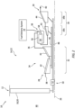
FIG. 2 is a partial schematic illustration of the aircraft system with a gas turbine engine. -
FIG. 3 is a schematic illustration of a combustor section of the gas turbine engine with a fuel delivery system. -
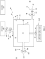
FIG. 4 is a partial schematic illustration of the fuel delivery system servicing the gas turbine engine, where the fuel delivery system includes a vented hydrogen fuel reservoir. -
FIG. 1 illustrates asystem 10 for an aircraft. The aircraft may be an airplane, a helicopter, a drone (e.g., an unmanned aerial vehicle (UAV)) or any other manned or unmanned aerial vehicle or system. Theaircraft system 10 may be configured as, or otherwise included as part of, a propulsion system for the aircraft. Theaircraft system 10 may also or alternatively be configured as, or otherwise included as part of, an electrical power system for the aircraft. Theaircraft system 10 ofFIG. 1 includes amechanical load 12 and an aircraft engine 14 configured to power operation of themechanical load 12. Theaircraft system 10 also include afuel delivery system 16 for the aircraft engine 14. - The
mechanical load 12 may be configured as or otherwise include a rotor 18 mechanically driven and/or otherwise powered by the aircraft engine 14. This driven rotor 18 may be a bladed propulsor rotor 20 (e.g., an air mover) where theaircraft system 10 is (or is part of) the aircraft propulsion system. The propulsor rotor 20 includes a plurality of rotor blades arranged circumferentially around and connected to at least (or only) one rotor base (e.g., a disk or a hub). The propulsor rotor 20 may be an open (e.g., un-ducted) propulsor rotor or a ducted propulsor rotor. Examples of the open propulsor rotor include a propeller rotor for a turboprop propulsion system, a rotorcraft rotor (e.g., a main helicopter rotor) for a turboshaft propulsion system, a propfan rotor for a propfan propulsion system, and a pusher fan rotor for a pusher fan propulsion system. An example of the ducted propulsor rotor is a fan rotor for a turbofan propulsion system. The present disclosure, however, is not limited to the foregoing exemplary propulsor rotor arrangements. Moreover, the driven rotor 18 may alternatively be a generator rotor of an electric power generator where theaircraft system 10 is (or is part of) the aircraft power system; e.g., an auxiliary power unit (APU) for the aircraft. - The aircraft engine 14 is configured as an internal combustion (IC) engine. The aircraft engine 14 of
FIG. 2 , for example, is configured as a gas turbine engine 22. The present disclosure, however, is not limited to such an exemplary aircraft engine configuration. The aircraft engine 14, for example, may alternatively be configured as or otherwise include a rotary engine (e.g., a Wankel cycle engine), a reciprocating piston engine (e.g., an inline (I) engine, a V-engine or a W-engine), or the like. - A
core 24 of the gas turbine engine 22 ofFIG. 2 extends axially along anaxis 26 between an upstream, forward end of theengine core 24 and a downstream, aft end of theengine core 24. Thisaxis 26 may be a centerline axis of the gas turbine engine 22 and/or itsengine core 24. Theaxis 26 may also or alternatively be a rotational axis of one or more rotating assemblies (e.g., 28 and 30) of the gas turbine engine 22 and itsengine core 24. Theengine core 24 ofFIG. 2 includes acompressor section 32, acombustor section 33, aturbine section 34 and acore flowpath 36. Theturbine section 34 ofFIG. 2 includes a high pressure turbine (HPT)section 34A and a low pressure turbine (LPT)section 34B; e.g., a power turbine (PT) section. Thecore flowpath 36 extends sequentially through thecompressor section 32, thecombustor section 33, theHPT section 34A and theLPT section 34B from anairflow inlet 38 into thecore flowpath 36 to a combustion products exhaust 40 from thecore flowpath 36. Thecore inlet 38 may be disposed at (e.g., on, adjacent or proximate) the forward end of theengine core 24, and thecore exhaust 40 may be disposed at the aft end of theengine core 24. - Each of the
engine sections - The
compressor rotors 42 are coupled to and rotatable with theHPT rotor 43. Thecompressor rotors 42 ofFIG. 2 , for example, are connected to theHPT rotor 43 by ahigh speed shaft 46. At least (or only) thecompressor rotors 42, theHPT rotor 43 and thehigh speed shaft 46 collectively form the highspeed rotating assembly 28; e.g., a high speed spool. TheLPT rotor 44 is connected to alow speed shaft 48. At least (or only) theLPT rotor 44 and thelow speed shaft 48 collectively form the lowspeed rotating assembly 30. This lowspeed rotating assembly 30 is further coupled to the driven rotor 18 (e.g., the propulsor rotor 20) through adrivetrain 50. Thedrivetrain 50 may be configured as a geared drivetrain, where a geartrain 52 (e.g., a transmission, a speed change device, an epicyclic geartrain, etc.) is disposed between and operatively couples the driven rotor 18 to the lowspeed rotating assembly 30 and itsLPT rotor 44. With this arrangement, the driven rotor 18 may rotate at a different (e.g., slower) rotational velocity than the lowspeed rotating assembly 30 and itsLPT rotor 44. However, thedrivetrain 50 may alternatively be configured as a direct drive drivetrain, where thegeartrain 52 is omitted. With this arrangement, the driven rotor 18 rotates at a common (the same) rotational velocity as the lowspeed rotating assembly 30 and itsLPT rotor 44. Referring again toFIG. 2 , each of therotating assemblies axis 26. - During operation of the gas turbine engine 22, air may be directed across the driven rotor 18 (e.g., the propulsor rotor 20) and into the
engine core 24 through thecore inlet 38. This air entering thecore flowpath 36 may be referred to as core air. The core air is compressed by thecompressor rotors 42 and directed into a combustion chamber 54 (e.g., an annular combustion chamber) within a combustor 56 (e.g., an annular combustor) of thecombustor section 33. Fuel is injected into thecombustion chamber 54 by one ormore fuel injectors 58 and mixed with the compressed core air to provide a fuel-air mixture. This fuel-air mixture is ignited and combustion products thereof flow through and sequentially cause theHPT rotor 43 and theLPT rotor 44 to rotate. The rotation of theHPT rotor 43 drives rotation of thecompressor rotors 42 and, thus, the compression of the air received from thecore inlet 38. The rotation of theLPT rotor 44 drives rotation of the driven rotor 18. Where the driven rotor 18 is configured as the propulsor rotor 20, the rotation of that propulsor rotor 20 may propel additional air (e.g., outside air, bypass air, etc.) outside of theengine core 24 to provide aircraft thrust and/or lift. Where the driven rotor 18 is configured as the generator rotor, the rotation of that generator rotor may facilitate generation of electricity. - Referring to
FIG. 3 , thefuel delivery system 16 is configured to deliver the fuel to thecombustor section 33 and itscombustor 56 for combustion. Thefuel delivery system 16 ofFIG. 3 , for example, includes afuel source 60, afuel supply circuit 62 and the one ormore fuel injectors 58. Thefuel source 60 ofFIG. 3 includes afuel reservoir 64 and afuel flow regulator 66; e.g., a valve and/or a pump. Thefuel reservoir 64 is configured to store the fuel before, during and/or after turbine engine operation. Thefuel flow regulator 66 is configured to direct and/or meter a flow of the fuel from thefuel reservoir 64 to thefuel injectors 58 through thefuel supply circuit 62. Thefuel injectors 58 may be arranged circumferentially about theaxis 26 in an array. Eachfuel injector 58 is configured to direct the fuel received from thefuel source 60 into thecombustion chamber 54 for mixing with the compressed core air to provide the fuel-air mixture. - The aircraft engine 14 of the present disclosure is configured as a non-hydrocarbon engine / a hydrocarbon free engine. The aircraft engine 14, more particularly, is configured as a hydrogen fueled engine. The fuel injected into the
combustion chamber 54 by thefuel injectors 58 is (or substantially includes) hydrogen (H2) fuel; e.g., H2 gas. Hydrogen fuel, however, is readily flammable / combustible when in the presence of oxygen and an ignition source; e.g., a flame, a spark, a relatively hot object, etc. Special care therefore is provided for storing the hydrogen fuel onboard the aircraft. Thefuel reservoir 64 ofFIG. 4 , for example, is a vented double walled hydrogen fuel reservoir. More particularly, thefuel reservoir 64 ofFIG. 4 includes ahydrogen storage vessel 68 and ahydrogen containment vessel 70. - The
hydrogen storage vessel 68 may form a primary fuel storage container for the aircraft engine 14 onboard the aircraft. Thehydrogen storage vessel 68 may be configured as a tank, a cylinder, a pressure vessel, a bladder or any other type of fuel storage container. Thehydrogen storage vessel 68 ofFIG. 4 , for example, has a storage vessel wall 72 (e.g., a sidewall) which forms an outer peripheral boundary of an enclosedhydrogen storage cavity 74 internal to thehydrogen storage vessel 68. Thehydrogen storage vessel 68 and itsstorage vessel wall 72 may be constructed from metal, a fiber-reinforced composite material or another suitable material. - The
hydrogen containment vessel 70 may form a fuel containment boundary for (e.g., an outer shell around) thehydrogen storage vessel 68. Thehydrogen containment vessel 70 may be configured as a tank, a cylinder, a pressure vessel, a bladder or any other type of fuel containment container. Thehydrogen containment vessel 70 ofFIG. 4 , for example, has a containment vessel wall 76 (e.g., a sidewall) which forms an outer peripheral boundary of an enclosedhydrogen containment cavity 78 internal to thehydrogen containment vessel 70. Thehydrogen containment vessel 70 and itscontainment vessel wall 76 may be constructed from metal, a fiber-reinforced composite material or another suitable material. The material forming thehydrogen containment vessel 70 and itscontainment vessel wall 76 may be the same or different than the material forming thehydrogen storage vessel 68 and itsstorage vessel wall 72. Thecontainment vessel wall 76, however, may have a reduced pressure capability and/or strength compared to thestorage vessel wall 72 since thehydrogen containment vessel 70 is provided to contain hydrogen fuel leaked out from thehydrogen storage vessel 68 whereas thehydrogen storage vessel 68 is provided to hold a bulk of the hydrogen fuel. Thecontainment vessel wall 76, for example, may have a thickness that is less than (e.g., up to five times (5x) less than) a thickness of thestorage vessel wall 72. The present disclosure, however, is not limited to such an arrangement. It is contemplated, for example, thehydrogen storage vessel 68 and thehydrogen containment vessel 70 may alternatively have similar or the same structural properties. - The
hydrogen storage vessel 68 ofFIG. 4 is disposed within thehydrogen containment vessel 70 and itshydrogen containment cavity 78. The fuel supply circuit 62 (a hydrogen supply circuit) fluidly couples thehydrogen storage cavity 74 to thefuel injectors 58 across thecontainment vessel wall 76. Thefuel supply circuit 62 ofFIG. 4 , for example, includes a fuel supply channel 80 (a hydrogen supply channel) which projects out from thestorage cavity 74 and through thecontainment vessel wall 76. - The
storage vessel wall 72 ofFIG. 4 is spaced inward from thecontainment vessel wall 76. With this arrangement, thefuel reservoir 64 has acontainment plenum 82 about (e.g., substantially or completely surrounding) thehydrogen storage vessel 68 and between thestorage vessel wall 72 and thecontainment vessel wall 76. Here, thestorage vessel wall 72 forms an inner peripheral boundary of thecontainment plenum 82. Thecontainment vessel wall 76 forms an outer peripheral boundary of thecontainment plenum 82. Thehydrogen containment vessel 70 and itscontainment vessel wall 76 may thereby contain (e.g., any) hydrogen fuel, which may leak out from the hydrogen storage vessel 68 (and/or fittings connected to the hydrogen storage vessel 68) during fuel delivery system operation, within thecontainment plenum 82. - The leaked hydrogen fuel may be purged / vented from the
hydrogen containment vessel 70 and thecontainment plenum 82 using aplenum purge circuit 84. Theplenum purge circuit 84 ofFIG. 4 includes aplenum purge channel 86 and aplenum purge valve 88 which is fluidly coupled to thecontainment plenum 82 along theplenum purge channel 86. Thisplenum purge circuit 84 is configured to selectively fluidly couple thecontainment plenum 82 to anenvironment 90 external to thefuel delivery system 16 and, for example, external to the aircraft. Theplenum purge circuit 84 ofFIG. 4 and itsplenum purge channel 86 project out from thehydrogen containment vessel 70 and itscontainment vessel wall 76 to anoutlet 92 to ambient. Theplenum purge circuit 84 may thereby discharge the leaked hydrogen fuel relatively far away from potential sources of ignition. However, when there is relatively little or no leaked hydrogen fuel, theplenum purge valve 88 may close to fluidly decouple thecontainment plenum 82 from theoutlet 92 / theexternal environment 90. - To further facilitate purging the leaked hydrogen fuel from the
containment plenum 82, thefuel reservoir 64 may be configured with an optionalplenum flushing circuit 94. Theflushing circuit 94 ofFIG. 4 includes a flushingchannel 96 and a flushingvalve 98 which is fluidly coupled to thecontainment plenum 82 along the flushingchannel 96. Thisflushing circuit 94 is configured to selectively fluidly couple thecontainment plenum 82 to a flushing fluid source such as anair source 100. Thisair source 100 may be configured as theexternal environment 90. Theflushing circuit 94, for example, may include an air pump 102 (e.g., an electric fan / blower) which directs ambient air from theexternal environment 90, through the flushingchannel 96, into thecontainment plenum 82. Alternatively, theair source 100 may be configured as a bleed from a flowpath of the aircraft engine 14; e.g., a core flowpath bleed, a bypass flowpath bleed, etc. With the foregoing arrangement, forced air is directed into thecontainment plenum 82 to flush out the leaked hydrogen fuel from thecontainment plenum 82 through theplenum purge circuit 84. In addition to flushing out the leaked hydrogen fuel, the air directed into thecontainment plenum 82 may also dilute the leaked hydrogen fuel. However, when there is relatively little or no leaked hydrogen fuel, the flushingvalve 98 may close to fluidly decouple theair source 100 from thecontainment plenum 82. - Under certain conditions, a quantity of the hydrogen fuel leaked from the
hydrogen storage vessel 68 into thecontainment plenum 82 may be relatively small. Under such conditions, theplenum purge circuit 84 may adequately purge the leaked hydrogen fuel and facilitate safe continued operation of thefuel delivery system 16. Under other conditions, however, the quantity of the hydrogen fuel leaked from thehydrogen storage vessel 68 into thecontainment plenum 82 may be relatively large. Acavity purge circuit 104 may thereby be provided to facilitate purging thestorage cavity 74 of some or all of its stored hydrogen fuel. Thecavity purge circuit 104 ofFIG. 4 includes acavity purge channel 106 and acavity purge valve 108 which is fluidly coupled to thestorage cavity 74 along thecavity purge channel 106. Thiscavity purge circuit 104 is configured to selectively fluidly couple thestorage cavity 74 to theexternal environment 90. Thecavity purge circuit 104 ofFIG. 4 and itscavity purge channel 106 project out from thehydrogen containment vessel 70 and itsstorage vessel wall 72, through thecontainment vessel wall 76, to anoutlet 110 to ambient. Thecavity purge circuit 104 may thereby discharge the stored hydrogen fuel relatively far away from potential sources of ignition as well as prevent overloading thehydrogen containment vessel 70 and/or theplenum purge circuit 84. However, when there is relatively little or no leaked hydrogen fuel, thecavity purge valve 108 may close to fluidly decouple thestorage cavity 74 from theoutlet 110/ theexternal environment 90. - In some embodiments, a
sensor 112 may be provided to measure a parameter of the leaked hydrogen fuel. Thesensor 112 ofFIG. 4 , for example, is a flow sensor which measures fluid flow out of thecontainment plenum 82. When the measured fluid flow is below a threshold, acontroller 114 controlling operation of the elements (e.g., 88, 98, 102 and 108) may determine the quantity of the leaked hydrogen fuel is relatively low and may signal thecavity purge valve 108 to close or remain closed. However, when the measured fluid flow is above the threshold, thecontroller 114 controlling operation of the elements (e.g., 88, 98, 102 and 108) may determine the quantity of the leaked hydrogen fuel is relatively high and may signal thecavity purge valve 108 to open. - In some embodiments, the
plenum purge circuit 84 and itsplenum purge channel 86 may be fluidly coupled to thecontainment plenum 82 at or about a gravitational bottom (e.g., lowest point) of thehydrogen containment vessel 70. With this arrangement, theplenum purge circuit 84 may also be used to purge / drain water (e.g., condensation) from thecontainment plenum 82. In other embodiments, theplenum purge circuit 84 and itsplenum purge channel 86 may be fluidly coupled to thecontainment plenum 82 at or about a gravitational top (e.g., highest point) of thehydrogen containment vessel 70; e.g., where there is a separate water drain for thecontainment plenum 82. With this arrangement, an inlet to theplenum purge circuit 84 may be located closer to a bulk mass of the leaked hydrogen fuel, if any, within thecontainment plenum 82 since the leaked hydrogen fuel (e.g., hydrogen gas) is less dense / lighter than air. - In some embodiments, the
plenum purge circuit 84 and itsplenum purge valve 88 may be selectively opened and closed based on presence, if any, of the leaked hydrogen fuel within thecontainment plenum 82. In other embodiments, theplenum purge circuit 84 and its plenum purge valve 88 (if still included) may (e.g., always) be open during normal operation to continually purge / vent the leaked hydrogen fuel, if any, from thecontainment plenum 82. - While various embodiments of the present disclosure have been described, it will be apparent to those of ordinary skill in the art that many more embodiments and implementations are possible within the scope of the disclosure. For example, the present disclosure as described herein includes several aspects and embodiments that include particular features. Although these features may be described individually, it is within the scope of the present disclosure that some or all of these features may be combined with any one of the aspects and remain within the scope of the disclosure. Accordingly, the present disclosure is not to be restricted except in light of the attached claims and their equivalents.
Claims (15)
- An assembly for an aircraft, comprising:a hydrogen containment vessel (70) comprising a containment vessel wall (76);a hydrogen storage vessel (68) including a storage vessel wall (72) and a storage cavity (74), the hydrogen storage vessel (68) disposed within the hydrogen containment vessel (70), and a containment plenum (82) disposed between the storage vessel wall (72) and the containment vessel wall (76);a hydrogen supply channel (80) fluidly coupled with the storage cavity (74);a cavity purge channel (106) fluidly coupled with the storage cavity (74); anda plenum purge channel (86) fluidly coupled with the containment plenum (82).
- The assembly of claim 1, further comprising:an aircraft engine (14) comprising a fuel injector (58);the fuel injector (58) fluidly coupled with the storage cavity (74) through the hydrogen supply channel (80).
- The assembly of claim 1 or 2, wherein the hydrogen supply channel (80) projects through the containment vessel wall (76).
- The assembly of any of claims 1 to 3, wherein the cavity purge channel (106) projects through the containment vessel wall (76).
- The assembly of any preceding claim, further comprising:a cavity purge circuit (104) configured to selectively fluidly couple the storage cavity (74) to an external environment (90);the cavity purge circuit (104) comprising the cavity purge channel (106).
- The assembly of claim 5, wherein the cavity purge circuit (104) further comprises a cavity purge valve (108) fluidly coupled to the storage cavity (74) by the cavity purge channel (106).
- The assembly of any preceding claim, further comprising:a plenum purge circuit (84) configured to selectively fluidly couple the containment plenum (82) to an external environment (90);the plenum purge circuit (84) comprising the plenum purge channel (86).
- The assembly of claim 7, wherein the plenum purge circuit (84) further comprises a plenum purge valve (88) fluidly coupled to the containment plenum (82) by the plenum purge channel (86).
- The assembly of any preceding claim, further comprising:a plenum purge circuit (84) configured to purge leaked hydrogen fuel from the containment plenum (82), the plenum purge circuit (84) comprising the plenum purge channel (86); anda cavity purge circuit (104) configured to purge stored hydrogen fuel from the storage cavity (74) when a parameter of the leaked hydrogen fuel is greater than a threshold, the cavity purge circuit (104) comprising the cavity purge channel (106).
- The assembly of any preceding claim, further comprising:a flushing circuit (94) fluidly coupled with the containment plenum (82);the flushing circuit (94) configured to direct air into the containment plenum (82) to flush out leaked hydrogen fuel through the plenum purge channel (86), optionally wherein the flushing circuit (94) comprises:an air pump (102); and/ora valve (98).
- The assembly of claim 10, further comprising an air source (100) selectively fluidly coupled to the containment plenum (82) through the flushing circuit (94), optionally wherein:the air source (100) comprises an external environment (90); orthe assembly further comprises an aircraft engine (14) comprising a fuel injector (58) and a flowpath (36), the fuel injector (58) fluidly coupled with the storage cavity (74) through the hydrogen supply channel (80), and the air source (100) comprising a bleed from the flowpath.
- An assembly for an aircraft, comprising:a hydrogen containment vessel (70) comprising a containment vessel wall (76);a hydrogen storage vessel (68) including a storage vessel wall (72) and a storage cavity (74), the hydrogen storage vessel (68) disposed within the hydrogen containment vessel (70), and a containment plenum (82) extending between the storage vessel wall (72) and the containment vessel wall (76);a hydrogen supply circuit (62) fluidly coupled with the storage cavity (74);a plenum purge circuit (84) fluidly coupled with the containment plenum (82); anda flushing circuit (94) fluidly coupled with the containment plenum (82), the flushing circuit (94) configured to direct fluid into the containment plenum (82) to flush out hydrogen fuel, which has leaked from the hydrogen storage vessel (68) into the containment plenum (82), through the plenum purge circuit (84).
- The assembly of claim 12, further comprising:a cavity purge circuit (104) fluidly coupled with the storage cavity (74);the cavity purge circuit (104) configured to selectively purge the hydrogen fuel out of the hydrogen storage vessel (68).
- A method of operation, comprising:supplying hydrogen fuel to a fuel injector (58) of an aircraft engine (14) from a storage vessel (68);purging leaked hydrogen fuel from a containment plenum (82) surrounding the storage vessel (68) to ambient; andpurging stored hydrogen fuel from an internal storage cavity (74) of the storage vessel (68) to ambient when a parameter of the leaked hydrogen fuel is above a threshold.
- The method of claim 14, further comprising directing air into the containment plenum (82) to flush the leaked hydrogen fuel out of the containment plenum (82), optionally wherein the air is directed into the containment plenum (82) using an electric fan (102).
Applications Claiming Priority (1)
| Application Number | Priority Date | Filing Date | Title |
|---|---|---|---|
| US18/367,288 US20250083831A1 (en) | 2023-09-12 | 2023-09-12 | Vented hydrogen fuel reservoir for aircraft engine |
Publications (1)
| Publication Number | Publication Date |
|---|---|
| EP4524382A1 true EP4524382A1 (en) | 2025-03-19 |
Family
ID=92791712
Family Applications (1)
| Application Number | Title | Priority Date | Filing Date |
|---|---|---|---|
| EP24200120.4A Pending EP4524382A1 (en) | 2023-09-12 | 2024-09-12 | Vented hydrogen fuel reservoir for aircraft engine |
Country Status (3)
| Country | Link |
|---|---|
| US (1) | US20250083831A1 (en) |
| EP (1) | EP4524382A1 (en) |
| CA (1) | CA3254166A1 (en) |
Citations (3)
| Publication number | Priority date | Publication date | Assignee | Title |
|---|---|---|---|---|
| US20140026597A1 (en) * | 2010-09-30 | 2014-01-30 | Michael Jay Epstein | Fuel storage system |
| US20150344145A1 (en) * | 2012-12-28 | 2015-12-03 | General Electric Company | Aircraft and a retrofit cryogenic fuel system |
| US20230027471A1 (en) * | 2021-07-14 | 2023-01-26 | Airbus Sas | Hydrogen tank assembly for a vehicle, such as an aircraft |
Family Cites Families (3)
| Publication number | Priority date | Publication date | Assignee | Title |
|---|---|---|---|---|
| US5085576A (en) * | 1990-07-10 | 1992-02-04 | Honeywell Inc. | Apparatus and method for detecting leaks in a system for delivering gaseous fuel |
| US5657631A (en) * | 1995-03-13 | 1997-08-19 | B.B.A. Research & Development, Inc. | Injector for turbine engines |
| WO2014194124A1 (en) * | 2013-05-29 | 2014-12-04 | Mcalister Technologies, Llc | Methods for fuel tank recycling and net hydrogen fuel and carbon goods production along with associated apparatus and systems |
-
2023
- 2023-09-12 US US18/367,288 patent/US20250083831A1/en active Pending
-
2024
- 2024-09-11 CA CA3254166A patent/CA3254166A1/en active Pending
- 2024-09-12 EP EP24200120.4A patent/EP4524382A1/en active Pending
Patent Citations (3)
| Publication number | Priority date | Publication date | Assignee | Title |
|---|---|---|---|---|
| US20140026597A1 (en) * | 2010-09-30 | 2014-01-30 | Michael Jay Epstein | Fuel storage system |
| US20150344145A1 (en) * | 2012-12-28 | 2015-12-03 | General Electric Company | Aircraft and a retrofit cryogenic fuel system |
| US20230027471A1 (en) * | 2021-07-14 | 2023-01-26 | Airbus Sas | Hydrogen tank assembly for a vehicle, such as an aircraft |
Also Published As
| Publication number | Publication date |
|---|---|
| CA3254166A1 (en) | 2025-05-30 |
| US20250083831A1 (en) | 2025-03-13 |
Similar Documents
| Publication | Publication Date | Title |
|---|---|---|
| US10774741B2 (en) | Hybrid propulsion system for a gas turbine engine including a fuel cell | |
| EP4276290A1 (en) | Purge system for a hydrogen fuel system | |
| US7485981B2 (en) | Aircraft combination engines complemental connection and operation | |
| US20200158213A1 (en) | Hybrid electric propulsion with superposition gearbox | |
| US11905914B2 (en) | Liquid hydrogen-liquid oxygen fueled powerplant | |
| EP4524377A1 (en) | Fuel containment structure for engine fuel delivery system | |
| EP4431399B1 (en) | Aircraft fuel system with removable fuel tank | |
| US20250083831A1 (en) | Vented hydrogen fuel reservoir for aircraft engine | |
| EP4520939A1 (en) | Selectable inlet for aircraft propulsion system heat exchanger | |
| EP4459116A1 (en) | Aircraft powerplant with steam system and bypass | |
| EP4245978B1 (en) | Systems and methods for starting a gas turbine engine | |
| US12234770B2 (en) | Gas turbine engine with hydrogen fuel system | |
| US20250084792A1 (en) | Fuel containment structure for engine fuel delivery system | |
| EP4726189A1 (en) | Aircraft powerplant with boosted turbine engine and fuel cell system | |
| US12486803B2 (en) | Gas turbine engine system with fuel driven turbine | |
| EP4636234A1 (en) | Monitoring fuel phase in aircraft powerplant fuel system | |
| EP4660533A1 (en) | Fuel nozzle for multifuel fuel delivery system | |
| US20250075656A1 (en) | Multi-fuel gas turbine engine with water injection | |
| EP4660535A1 (en) | Gaseous fuel nozzle for turbine engine powerplant | |
| US20260104009A1 (en) | Enhanced recuperation cycle for aircraft powerplant turbine engine |
Legal Events
| Date | Code | Title | Description |
|---|---|---|---|
| PUAI | Public reference made under article 153(3) epc to a published international application that has entered the european phase |
Free format text: ORIGINAL CODE: 0009012 |
|
| STAA | Information on the status of an ep patent application or granted ep patent |
Free format text: STATUS: THE APPLICATION HAS BEEN PUBLISHED |
|
| AK | Designated contracting states |
Kind code of ref document: A1 Designated state(s): AL AT BE BG CH CY CZ DE DK EE ES FI FR GB GR HR HU IE IS IT LI LT LU LV MC ME MK MT NL NO PL PT RO RS SE SI SK SM TR |
|
| STAA | Information on the status of an ep patent application or granted ep patent |
Free format text: STATUS: REQUEST FOR EXAMINATION WAS MADE |
|
| 17P | Request for examination filed |
Effective date: 20250919 |