EP4524378A1 - Method for the production or treatment of at least one industrial gas with high- efficiency centralised heat supply - Google Patents
Method for the production or treatment of at least one industrial gas with high- efficiency centralised heat supply Download PDFInfo
- Publication number
- EP4524378A1 EP4524378A1 EP23306530.9A EP23306530A EP4524378A1 EP 4524378 A1 EP4524378 A1 EP 4524378A1 EP 23306530 A EP23306530 A EP 23306530A EP 4524378 A1 EP4524378 A1 EP 4524378A1
- Authority
- EP
- European Patent Office
- Prior art keywords
- stream
- heat
- gas
- expanded
- streams
- Prior art date
- Legal status (The legal status is an assumption and is not a legal conclusion. Google has not performed a legal analysis and makes no representation as to the accuracy of the status listed.)
- Pending
Links
Images

Classifications
-
- F—MECHANICAL ENGINEERING; LIGHTING; HEATING; WEAPONS; BLASTING
- F01—MACHINES OR ENGINES IN GENERAL; ENGINE PLANTS IN GENERAL; STEAM ENGINES
- F01K—STEAM ENGINE PLANTS; STEAM ACCUMULATORS; ENGINE PLANTS NOT OTHERWISE PROVIDED FOR; ENGINES USING SPECIAL WORKING FLUIDS OR CYCLES
- F01K23/00—Plants characterised by more than one engine delivering power external to the plant, the engines being driven by different fluids
- F01K23/02—Plants characterised by more than one engine delivering power external to the plant, the engines being driven by different fluids the engine cycles being thermally coupled
- F01K23/06—Plants characterised by more than one engine delivering power external to the plant, the engines being driven by different fluids the engine cycles being thermally coupled combustion heat from one cycle heating the fluid in another cycle
- F01K23/064—Plants characterised by more than one engine delivering power external to the plant, the engines being driven by different fluids the engine cycles being thermally coupled combustion heat from one cycle heating the fluid in another cycle in combination with an industrial process, e.g. chemical, metallurgical
-
- F—MECHANICAL ENGINEERING; LIGHTING; HEATING; WEAPONS; BLASTING
- F25—REFRIGERATION OR COOLING; COMBINED HEATING AND REFRIGERATION SYSTEMS; HEAT PUMP SYSTEMS; MANUFACTURE OR STORAGE OF ICE; LIQUEFACTION SOLIDIFICATION OF GASES
- F25J—LIQUEFACTION, SOLIDIFICATION OR SEPARATION OF GASES OR GASEOUS OR LIQUEFIED GASEOUS MIXTURES BY PRESSURE AND COLD TREATMENT OR BY BRINGING THEM INTO THE SUPERCRITICAL STATE
- F25J3/00—Processes or apparatus for separating the constituents of gaseous or liquefied gaseous mixtures involving the use of liquefaction or solidification
- F25J3/02—Processes or apparatus for separating the constituents of gaseous or liquefied gaseous mixtures involving the use of liquefaction or solidification by rectification, i.e. by continuous interchange of heat and material between a vapour stream and a liquid stream
- F25J3/0204—Processes or apparatus for separating the constituents of gaseous or liquefied gaseous mixtures involving the use of liquefaction or solidification by rectification, i.e. by continuous interchange of heat and material between a vapour stream and a liquid stream characterised by the feed stream
- F25J3/0209—Natural gas or substitute natural gas
-
- F—MECHANICAL ENGINEERING; LIGHTING; HEATING; WEAPONS; BLASTING
- F25—REFRIGERATION OR COOLING; COMBINED HEATING AND REFRIGERATION SYSTEMS; HEAT PUMP SYSTEMS; MANUFACTURE OR STORAGE OF ICE; LIQUEFACTION SOLIDIFICATION OF GASES
- F25J—LIQUEFACTION, SOLIDIFICATION OR SEPARATION OF GASES OR GASEOUS OR LIQUEFIED GASEOUS MIXTURES BY PRESSURE AND COLD TREATMENT OR BY BRINGING THEM INTO THE SUPERCRITICAL STATE
- F25J3/00—Processes or apparatus for separating the constituents of gaseous or liquefied gaseous mixtures involving the use of liquefaction or solidification
- F25J3/02—Processes or apparatus for separating the constituents of gaseous or liquefied gaseous mixtures involving the use of liquefaction or solidification by rectification, i.e. by continuous interchange of heat and material between a vapour stream and a liquid stream
- F25J3/0228—Processes or apparatus for separating the constituents of gaseous or liquefied gaseous mixtures involving the use of liquefaction or solidification by rectification, i.e. by continuous interchange of heat and material between a vapour stream and a liquid stream characterised by the separated product stream
- F25J3/0233—Processes or apparatus for separating the constituents of gaseous or liquefied gaseous mixtures involving the use of liquefaction or solidification by rectification, i.e. by continuous interchange of heat and material between a vapour stream and a liquid stream characterised by the separated product stream separation of CnHm with 1 carbon atom or more
-
- F—MECHANICAL ENGINEERING; LIGHTING; HEATING; WEAPONS; BLASTING
- F25—REFRIGERATION OR COOLING; COMBINED HEATING AND REFRIGERATION SYSTEMS; HEAT PUMP SYSTEMS; MANUFACTURE OR STORAGE OF ICE; LIQUEFACTION SOLIDIFICATION OF GASES
- F25J—LIQUEFACTION, SOLIDIFICATION OR SEPARATION OF GASES OR GASEOUS OR LIQUEFIED GASEOUS MIXTURES BY PRESSURE AND COLD TREATMENT OR BY BRINGING THEM INTO THE SUPERCRITICAL STATE
- F25J3/00—Processes or apparatus for separating the constituents of gaseous or liquefied gaseous mixtures involving the use of liquefaction or solidification
- F25J3/02—Processes or apparatus for separating the constituents of gaseous or liquefied gaseous mixtures involving the use of liquefaction or solidification by rectification, i.e. by continuous interchange of heat and material between a vapour stream and a liquid stream
- F25J3/0228—Processes or apparatus for separating the constituents of gaseous or liquefied gaseous mixtures involving the use of liquefaction or solidification by rectification, i.e. by continuous interchange of heat and material between a vapour stream and a liquid stream characterised by the separated product stream
- F25J3/0238—Processes or apparatus for separating the constituents of gaseous or liquefied gaseous mixtures involving the use of liquefaction or solidification by rectification, i.e. by continuous interchange of heat and material between a vapour stream and a liquid stream characterised by the separated product stream separation of CnHm with 2 carbon atoms or more
-
- F—MECHANICAL ENGINEERING; LIGHTING; HEATING; WEAPONS; BLASTING
- F25—REFRIGERATION OR COOLING; COMBINED HEATING AND REFRIGERATION SYSTEMS; HEAT PUMP SYSTEMS; MANUFACTURE OR STORAGE OF ICE; LIQUEFACTION SOLIDIFICATION OF GASES
- F25J—LIQUEFACTION, SOLIDIFICATION OR SEPARATION OF GASES OR GASEOUS OR LIQUEFIED GASEOUS MIXTURES BY PRESSURE AND COLD TREATMENT OR BY BRINGING THEM INTO THE SUPERCRITICAL STATE
- F25J2200/00—Processes or apparatus using separation by rectification
- F25J2200/50—Processes or apparatus using separation by rectification using multiple (re-)boiler-condensers at different heights of the column
-
- F—MECHANICAL ENGINEERING; LIGHTING; HEATING; WEAPONS; BLASTING
- F25—REFRIGERATION OR COOLING; COMBINED HEATING AND REFRIGERATION SYSTEMS; HEAT PUMP SYSTEMS; MANUFACTURE OR STORAGE OF ICE; LIQUEFACTION SOLIDIFICATION OF GASES
- F25J—LIQUEFACTION, SOLIDIFICATION OR SEPARATION OF GASES OR GASEOUS OR LIQUEFIED GASEOUS MIXTURES BY PRESSURE AND COLD TREATMENT OR BY BRINGING THEM INTO THE SUPERCRITICAL STATE
- F25J2260/00—Coupling of processes or apparatus to other units; Integrated schemes
- F25J2260/02—Integration in an installation for exchanging heat, e.g. for waste heat recovery
-
- F—MECHANICAL ENGINEERING; LIGHTING; HEATING; WEAPONS; BLASTING
- F25—REFRIGERATION OR COOLING; COMBINED HEATING AND REFRIGERATION SYSTEMS; HEAT PUMP SYSTEMS; MANUFACTURE OR STORAGE OF ICE; LIQUEFACTION SOLIDIFICATION OF GASES
- F25J—LIQUEFACTION, SOLIDIFICATION OR SEPARATION OF GASES OR GASEOUS OR LIQUEFIED GASEOUS MIXTURES BY PRESSURE AND COLD TREATMENT OR BY BRINGING THEM INTO THE SUPERCRITICAL STATE
- F25J2290/00—Other details not covered by groups F25J2200/00 - F25J2280/00
- F25J2290/72—Processing device is used off-shore, e.g. on a platform or floating on a ship or barge
Definitions
- the present disclosure relates to a gas production or treatment method for producing or treating an industrial gas, which includes producing or treating the industrial gas by a plant comprising a plurality of heat-receiving units that are thermally independent from one another.
- the disclosure also relates to a corresponding gas production or treatment installation, that is capable of producing or treating the industrial gas.
- the term "industrial gas” is used to refer to any fluid used industrially, whether it be in gaseous or liquid state.
- the industrial gas may comprise, for example, liquefied petroleum gas (or LPG), ethylene, or liquefied natural gas (LNG).
- LPG liquefied petroleum gas
- LNG liquefied natural gas
- the production plant may comprise, for example, a petrochemical plant, a refinery, an LNG plant, or a floating production, storage and offloading ("FPSO", as per accepted terminology) unit.
- such a production plant comprises a plurality of heat-receiving units that may be referred to herein as thermally independent from one another, in the sense that the load rate of one does not directly influence the load rate of the other. As a consequence, the amounts of heat received by these units are not directly linked one with another.
- the heat-receiving units may also generally have a clearly identifiable function: reboiler at the bottom of a distillation or separation column, such as a debutaniser, etc.
- the load rate can be understood as the quantity of gas/product handled by the different process units of a plant.
- a plant is usually divided in different process units that achieve different tasks, such as transformation or purification. Due to these different tasks, the heat amounts received by the different units are not proportional or linked in a way to the plant capacity.
- heat transfer fluids used to supply heat to the heat-receiving units: steam, hot water, and hot oil.
- These high temperature heat transfer fluids are typically produced by boilers or furnaces, or by recovering heat from the exhaust gases from one or more gas turbines.
- the heating fluids may be heated by combustion and are therefore generally not decarbonised or carbon neutral (i.e. they do not serve to reduce greenhouse gas (GHG) and carbon dioxide emissions).
- Heat transfer fluids may also be heated using any of a variety of boilers, heaters or electric furnaces.
- thermal performance (efficiency) of such equipment units can be limited. For example, 1 MW of electricity is consumed in order to produce a little less than 1 MW of heat.
- Thermodynamic systems may also be used that are capable of supplying heat to a heat-receiving unit, for example by using the waste heat from this unit and an external energy source.
- these systems are difficult to balance, in particular during the start-up phase of the heat-receiving unit, or in the event of a change in its load. This adds to the complexity of operation.
- One aspect of the disclosure is therefore to improve performance metrics of gas processing systems and methods, At least one aspect, for example, is to provide a gas production method for producing at least one industrial gas which reduces greenhouse gas emissions, CO2 in particular, without increasing energy costs to any significant extent, and which is easy to implement operationally.
- an aspect of the disclosure relates to a gas production method for producing at least one industrial gas, a method comprising:
- the method includes one or more of the following characteristic features, taken into consideration in isolation or in accordance with any technically feasible combination:
- Another aspect of the disclosure relates to a gas production installation for producing at least one industrial gas comprising:
- the arrows represent without distinction the material flows of a method according to the disclosure, and the pipes, or pipe systems, that convey these flows in an installation according to the disclosure.
- the industrial gas may comprise, for example, LPG, ethylene, anthropogenic CO2, or any other industrial gas known per se.
- the installation 10 is for example on land.
- the installation 10 may comprise, for example, an FPSO.
- a Floating Production Storage and Offloading (FPSO) vessel may include a floating vessel that acts as a mobile offshore production and storage facility equipped with processing equipment for the separation, storage and offloading of hydrocarbons. When such hydrocarbons are processed, they may be safely stored in the FPSO until it can be offloaded onto a tanker or a pipeline for transportation ashore.
- FPSO Floating Production Storage and Offloading
- the installation 10 includes a plant 12 that is capable of producing or treating at least the said industrial gas, this plant being represented, in part, in the form of a plurality of heat-receiving units 14, 16, 17, 18, 20.
- the term "heat-receiving unit” may be used herein to generally describe any component of the plant 12 that, in its operation, receives heat to perform a component function.
- the heat-receiving units 14, 16, 17, 18, and 20 are thermally independent from one another, and at least one heat source 22 that is preferably thermally independent from the heat-receiving units.
- the term "thermally independent" is used to indicate, for example, that the load rate of one of the heat-receiving units 14 to 20 does not directly or appreciably influence the load rate of another. Additionally, the heat requirements of one may not be linked to the heat requirements of the others, nor to the availability of the heat source 22.
- the heat-receiving units have distinct and identifiable functions within the plant 12.
- the heat-receiving units 14, 16, 17, 18, and 20 are along parallel material flow paths as represented by the arrows.
- the heat-receiving units may also be distinct structures, such that one heat-receiving unit may be interconnected within the plant 12 along a material flow path separately from another heat-receiving unit.
- the heat-receiving units 14, 16, 17, 18, and 20 may also be physically separated, as shown, such although they may be interconnected in terms of flow path the structure of the heat-receiving units are not in direct thermal engagement with one another.
- the installation 10 includes, for example, a heat exchanger 52 that is capable of superheating the gas stream 50 by heat exchange with the second expanded stream 42 and of producing a superheated gas 54, with the said working gas 28 comprising at least the superheated gas.
- a heat exchanger 52 that is capable of superheating the gas stream 50 by heat exchange with the second expanded stream 42 and of producing a superheated gas 54, with the said working gas 28 comprising at least the superheated gas.
- the installation 10 does not include such an exchanger 52, and the working gas 28 comprises at least the gas stream 50.
- the working gas 28 comprises, and according to one particular embodiment is, a hydrocarbon or a mixture of hydrocarbons, in particular ethane, propane, butane, pentane, isopentane and cyclopentane.
- the proportion thereof is at least 70% by mass.
- the mixture of hydrocarbons comprises, in a proportion of at least 70% by mass, of propane, butane, or a mixture of propane and butane.
- the working gas comprises at least 80% by mass of butane.
- the working gas 28 comprises, at least 80% by mass, of CO2 or ammonia. According to one particular embodiment, the working gas 28 is CO2 or ammonia.
- the plant 12 in addition includes two additional units 78, 80 that are thermally independent from the heat-receiving units 14 to 20 and from the heat source 22, and that consume heat at a lower temperature level than the heat-receiving units 14 to 20.
- the plant 12 also comprises at least one other additional unit 82 that is thermally independent from the heat-receiving units 14 to 20 and from the heat source 22, and that consumes heat at a lower temperature level than the two additional units 78, 80.
- the heat-receiving units 14 to 20 are a distillation column or separation column reboiler, or more generally a heater for liquid, gas or a two-phase mixture.
- the heat-receiving units 14 to 20 are at least five in number.
- the heat source 22 is, for example, one referred to as a "waste" heat source, or simply a stream of water (not represented) to be cooled, this stream being capable of transferring its heat.
- the two additional units 78, 80 are a de-icing heater, a washing column reboiler, or more generally a heater for liquid, gas or a two-phase mixture.
- the other additional unit 82 is a feed gas preheater, or more generally a heater for liquid, gas or a two-phase mixture.
- the first subsystem 38 comprises, for example, a first capacitor 84 that is capable of receiving the one or more expanded stream(s) 40 at the second expansion pressure P2.
- the second sub-system 44 comprises, for example, a second capacitor 90 that is capable of receiving, in particular, an expanded stream 92 resulting from the expansion of the second expanded stream 42.
- the compression unit 24 comprises, for example, a compressor 93, advantageously a centrifugal compressor.
- the compression unit 24 comprises a main inlet 94 for the working gas 28, an outlet 96 for the compressed gas 26, and in the example two additional inlets 98, 100 for receiving a first gas stream 102 and a second gas stream 104 from the first capacitor 84 and the second capacitor 90 respectively.
- the operation of the installation 10 illustrates a method according to the disclosure and will hereinafter be described.
- the installation 10 is capable of operationally implementing this method according to the disclosure.
- the working gas 28 constitutes a working fluid which circulates in gaseous, liquid, or possibly two-phase form in a closed circuit 106 (with the exception of any eventual make-up and purging) formed by the installation 10.
- the working gas 28 is supplied by the plant 12 itself.
- the working gas 28 originates from another source (not represented).
- a step a) the industrial gas is produced by the plant 12.
- the compressed gas 26 is obtained by compressing at least the working gas 28 in the compression unit 24.
- the working gas 28 is, for example, at a pressure of 2 bar absolute and at 40°C.
- the compressed gas 26 is for example at 34 bar absolute and 150°C.
- a step c) the compressed gas 26 is divided by the dividers 30 in order to obtain the plurality of compressed gas streams 32.
- the heat exchanges are respectively brought about between the plurality of compressed gas streams 32 and the heat-receiving units 14 to 20 in the exchangers 34, with the compressed gas streams releasing and transferring heat respectively to the heat-receiving units, and condensing so as to form the plurality of liquid streams 36.
- the liquid streams 36 are, for example, at approximately 33 bar absolute and 140°C.
- the liquid streams 36 are expanded in order to obtain the expanded streams 40, and the expanded stream 46 is obtained at the first expansion pressure P1.
- the expanded stream 46 is, for example, at 2.2 bar absolute (first expansion pressure) and 18°C.
- liquid streams 36 are combined together and expanded so as to form a single expanded stream (not represented).
- the step e) includes a sub-step e1), in which the liquid streams 36 are expanded in order to obtain the expanded streams 40, and the second expanded stream 42 is obtained from the one or more expanded stream(s) 40 at the second expansion pressure P2.
- the second expansion pressure P2 is, for example, approximately 10 to 15 bar absolute.
- the step e) also includes a sub-step e2), in which the expanded stream 46 is obtained at the first expansion pressure P1, this obtaining of the stream comprising at least one expansion of the second expanded stream 42, for example in a valve 107.
- a step f the expanded stream 46 is vaporised in the evaporator 48 by heat exchange with the heat source 22, and the gas stream 50 is obtained.
- the gas stream 50 is then superheated in the heat exchanger 52 by heat exchange with the second expanded stream 42, in order to obtain the superheated gas 54, for example at 40°C.
- the working gas 28 is obtained from at least the gas stream 50 (possibly superheated), and is advantageously stored in the storage capacitor 64.
- At least the fraction 58 of the compressed gas 26 is condensed by heat exchange with the coolant fluid 60 in order to obtain the liquid stream 62. This is carried out, for example, when the heat requirement of the heat-receiving units 14 to 20 is less than a nominal requirement, corresponding to the quantity of heat that the compressed gas 26 could release and transfer by condensing completely.
- At least a fraction 108 of the liquid stream 62 is expanded in order to obtain a stream 110 at the second expansion pressure P2.
- the second expanded stream 42 used in implementation in the sub-step e2) is obtained at least from the said stream 110.
- At least a fraction 112 of the liquid stream 62 is expanded in order to obtain a stream 114.
- the fraction 70 of the compressed gas 26 obtained in the step b) is expanded in order to obtain the gas stream 72.
- the working gas 28 is obtained at least in part from the said gas stream 72 and the said stream 114.
- the fraction 74 of the compressed gas 26 is expanded in order to produce the stream 76 that is sent directly to the first sub-system 38 without passing through the heat-receiving units 14 to 20.
- the expanded streams 40 are received in the first capacitor 84 at the second expansion pressure P2.
- the second expanded stream 42 is liquid and extracted at the bottom of the first capacitor 84.
- a first gas stream 116 is extracted at the top of the first capacitor 84, and for example is at 80-120°C.
- the first gas stream 116 is divided into at least two gas streams 118, 120 which transfer heat to the two additional units 78, 80 by condensing in order to form two liquid streams 122, 124.
- the two liquid streams 122, 124 are expanded and sent to the second capacitor 90.
- step b) at least a fraction 102 of the first gas stream 116 is compressed in the compression unit 24 in order to obtain the compressed gas 26.
- the totality of the first gas stream 116 is compressed if the two additional units 78, 80 do not require heat.
- the expansion of the second expanded stream 42 produces, for example, the expanded stream 92 that is received in the second capacitor 90.
- the second capacitor 90 is at a third expansion pressure P3, which lies between the first expansion pressure P1 and the second expansion pressure P2.
- the third expansion pressure P3 is, for example, 5-6 bar absolute.
- a first liquid stream 126 is extracted at the bottom of the second capacitor 90, and a second gas stream 128 is extracted at the top of the second capacitor, for example at a temperature of 30 to 60°C. At least a portion 130 of the second gas stream 128 transfers heat to the other additional unit 82 by condensing so as to form a second liquid stream 132.
- the first liquid stream 126 and the second liquid stream 132 are expanded in order to obtain the expanded stream 46.
- At least the fraction 104 of the second gas stream 128 is compressed in order to obtain the compressed gas 26.
- the totality of the second gas stream 128 is compressed if the other additional unit 82 does not require heat.
- the supply of heat to the heat-receiving units 14 to 20, and possibly 78, 80, 82 does not necessitate either resorting to the combustion of hydrocarbons in furnaces or boilers, or to electric heating.
- the industrial gas produced or treated in the plant 12 is therefore at least in part decarbonised, while providing a good level of performance (efficiency).
- the heat produced and transferred to the heat-receiving units is produced with a high degree of efficiency: 1 MW of electricity consumed in the compression unit 24 being able to supply up to 4 MW of thermal power produced and transferred to the heat-receiving units.
- the Coefficient of Performance (COP) is therefore around 4.
- the method is also simple to implement in operation, thanks to the heat-receiving units 14 to 20 and the heat source 22 being independent of each other.
- the steps b) to h) may be started up with a minimum heat demand on the part of the heat-receiving units, and in a manner that is not correlated with the start-up of the units of the plant 12.
- the working fluid may advantageously be produced on site by the plant 12. All of the equipment units used in operation in order to carry out the steps of the method are readily available and often already used individually in an industrial gas production or treatment plant.
- the disclosure provides the means for supplying heat to numerous units, and potentially to the entire plant 12, in a centralised manner.
- FIG 2 represents an installation 200 according to one other example embodiment of the disclosure.
- the installation 200 is similar to the installation 10 represented in Figure 1 in certain respects.
- the similar elements therein bear the same numerical references and will not be described again.
- the plant 12 includes, for example, only two heat-receiving units, or only two of the units thereof are supplied with heat by the working fluid circulating in the circuit 106.
- the plant 12 may omit the units 78, 80, 82 shown in Figure 1 , or these units do not receive heat from the working fluid and are therefore not represented.
- the installation 200 may include only the first subsystem 38, which is simplified, and may omit the subsystem 37 shown in Figure 1 .
- the first sub-system 38 does not include the first capacitor 84, and for example is limited to two expansion valves 202, 204.
- the installation 200 does not include the heat exchanger 52 represented in Figure 1 .
- the expanded stream 46 is obtained, for example, directly after combining together the expanded streams 40.
- the expanded stream 46 is, for example, a liquid or a two-phase stream (with a liquid phase and a gaseous phase).
- the entirety of the liquid stream 62 derived from the fraction 58 of the compressed gas 26 may possibly be expanded in order to obtain the stream 114.
- fraction 74 of the compressed gas be expanded and sent directly to the first sub-system 38.
- the installation 200 although simplified, operates in a manner analogous to the installation 10 and offers similar advantages.
Landscapes
- Engineering & Computer Science (AREA)
- Mechanical Engineering (AREA)
- General Engineering & Computer Science (AREA)
- Physics & Mathematics (AREA)
- Thermal Sciences (AREA)
- Chemical & Material Sciences (AREA)
- Combustion & Propulsion (AREA)
- Chemical Kinetics & Catalysis (AREA)
- General Chemical & Material Sciences (AREA)
- Oil, Petroleum & Natural Gas (AREA)
- Separation By Low-Temperature Treatments (AREA)
Abstract
a) producing or treating an industrial gas by a plant (12) comprising heat-receiving units thermally independent from one another, and at least one heat source (22),
b) obtaining a compressed gas (26) by compressing a working gas (28),
c) dividing the compressed gas into compressed gas streams (32),
d) performing heat exchanges between the compressed gas streams and the heat-receiving units, and condensing the compressed gas streams into liquid streams (36),
e) expanding the liquid streams and obtaining an expanded stream (46),
f) vaporizing the expanded stream by heat exchange with at least the heat source, and obtaining of a gas stream (50),
g) obtaining the working gas from at least the gas stream.
Description
- The present disclosure relates to a gas production or treatment method for producing or treating an industrial gas, which includes producing or treating the industrial gas by a plant comprising a plurality of heat-receiving units that are thermally independent from one another.
- The disclosure also relates to a corresponding gas production or treatment installation, that is capable of producing or treating the industrial gas.
- For the purposes and within the meaning of this application, the term "industrial gas" is used to refer to any fluid used industrially, whether it be in gaseous or liquid state. The industrial gas may comprise, for example, liquefied petroleum gas (or LPG), ethylene, or liquefied natural gas (LNG). The production plant may comprise, for example, a petrochemical plant, a refinery, an LNG plant, or a floating production, storage and offloading ("FPSO", as per accepted terminology) unit.
- In one or more example configurations, such a production plant comprises a plurality of heat-receiving units that may be referred to herein as thermally independent from one another, in the sense that the load rate of one does not directly influence the load rate of the other. As a consequence, the amounts of heat received by these units are not directly linked one with another. The heat-receiving units may also generally have a clearly identifiable function: reboiler at the bottom of a distillation or separation column, such as a debutaniser, etc. The load rate can be understood as the quantity of gas/product handled by the different process units of a plant.
- A plant is usually divided in different process units that achieve different tasks, such as transformation or purification. Due to these different tasks, the heat amounts received by the different units are not proportional or linked in a way to the plant capacity.
- There are three main types of heat transfer fluids used to supply heat to the heat-receiving units: steam, hot water, and hot oil. These high temperature heat transfer fluids are typically produced by boilers or furnaces, or by recovering heat from the exhaust gases from one or more gas turbines. As a result, the heating fluids may be heated by combustion and are therefore generally not decarbonised or carbon neutral (i.e. they do not serve to reduce greenhouse gas (GHG) and carbon dioxide emissions).
- Heat transfer fluids may also be heated using any of a variety of boilers, heaters or electric furnaces. However, the thermal performance (efficiency) of such equipment units can be limited. For example, 1 MW of electricity is consumed in order to produce a little less than 1 MW of heat.
- Thermodynamic systems may also be used that are capable of supplying heat to a heat-receiving unit, for example by using the waste heat from this unit and an external energy source. However, these systems are difficult to balance, in particular during the start-up phase of the heat-receiving unit, or in the event of a change in its load. This adds to the complexity of operation.
- One aspect of the disclosure is therefore to improve performance metrics of gas processing systems and methods, At least one aspect, for example, is to provide a gas production method for producing at least one industrial gas which reduces greenhouse gas emissions, CO2 in particular, without increasing energy costs to any significant extent, and which is easy to implement operationally.
- To this end, an aspect of the disclosure relates to a gas production method for producing at least one industrial gas, a method comprising:
- a) producing or treating an industrial gas by a plant comprising a plurality of heat-receiving units that are thermally independent from one another, the plant comprising at least one heat source;
- b) obtaining a compressed gas by compressing at least one working gas;
- c) dividing the compressed gas in order to obtain a plurality of compressed gas streams;
- d) performing heat exchanges respectively between the plurality of compressed gas streams and the heat-receiving units, the compressed gas streams releasing and transferring heat respectively to the heat-receiving units, and the compressed gas streams condensing so as to form a plurality of liquid streams;
- e) expanding the liquid streams in order to obtain one or more expanded stream(s), and obtaining an expanded stream from at least the expanded streams, the expanded stream being at a first expansion pressure;
- f) vaporizing the expanded stream by heat exchange with at least said heat source, and obtaining a gas stream; and
- g) obtaining the working gas from at least the gas stream.
- According to other aspects of the disclosure, the method includes one or more of the following characteristic features, taken into consideration in isolation or in accordance with any technically feasible combination:
- the working gas comprises a hydrocarbon, a mixture of hydrocarbons, CO2, or ammonia;
- the heat-receiving units are capable of heating a liquid, a gas or a two-phase mixture;
- for at least a certain period of time, at least a fraction of the compressed gas obtained in step b) is condensed by heat exchange with a coolant fluid in order to obtain a liquid stream;
- in addition to or in substitution of steps c), d), e), f) and g), at least a fraction of the said liquid stream is expanded in order to obtain a stream, and a fraction of the compressed gas obtained in step b) is expanded in order to obtain a gas stream; and the working gas compressed in step b) is obtained at least in part from the said gas stream and the said stream;
- step e) includes:
- e1) expanding the liquid streams in order to obtain the one or more expanded stream(s), and obtaining a second expanded stream which is at least partially liquid from the one or more expanded stream(s), the second expanded stream being at a second expansion pressure;
- e2) obtaining the expanded stream, with the first expansion pressure being lower than the second expansion pressure, obtaining of the expanded stream comprising at least one expansion of the second expanded stream;
- in addition to or in substitution of steps c), d), and sub-step e1), at least a fraction of said liquid stream is expanded in order to obtain an expanded stream at the second expansion pressure, the second expanded stream used in sub-step e2) being obtained at least from the said expanded stream;
- the plant comprises at least a first additional unit that is thermally independent from the heat-receiving units and from the heat source, the first additional unit receiving heat at a lower temperature level than the heat-receiving units; in sub-step e1), the one or more expanded stream(s) are received in a first capacitor at the second expansion pressure, the second expanded stream being liquid and extracted at the bottom of the first capacitor, a first gas stream being extracted at the top of the first capacitor; and at least a portion of the first gas stream transfers heat to the first additional unit by condensing so as to form a liquid stream;
- in step b), at least a fraction of the first gas stream is compressed in order to obtain the compressed gas;
- the plant includes at least one second additional unit that is thermally independent from the heat-receiving units, from the first additional unit and from the heat source, the second additional unit receiving heat at a lower temperature level than the first additional unit; and in sub-step e2), the expansion of the second expanded stream produces an expanded stream that is received in a second capacitor, a first liquid stream being extracted at the bottom of the second capacitor, a second gas stream being extracted at the top of the second capacitor, at least a portion of the second gas stream transferring heat to the second additional unit by condensing so as to form a second liquid stream, the first liquid stream and the second liquid stream being expanded in order to obtain the expanded stream; and
- in step b), at least a fraction of the second gas stream is compressed in order to obtain the compressed gas.
- Another aspect of the disclosure relates to a gas production installation for producing at least one industrial gas comprising:
- a) a plant capable of producing or treating an industrial gas, the plant comprising a plurality of heat-receiving units that are thermally independent from one another, the plant comprising at least one heat source;
- b) a compression unit that is capable of producing a compressed gas from at least one working gas;
- c) one or more dividers that are capable of dividing the compressed gas into a plurality of compressed gas streams;
- d) heat exchangers adapted for performing heat exchanges respectively between the plurality of compressed gas streams and the heat-receiving units, the compressed gas streams releasing and transferring heat respectively to the heat-receiving units, and condensing so as to form a plurality of liquid streams;
- e) a fluid expansion system that is capable of expanding the liquid streams in order to obtain one or more expanded stream(s), and obtain an expanded stream from at least the expanded streams, the expanded stream being at a first expansion pressure; and
- f) an evaporator that is capable of vaporizing the expanded stream, by heat exchange with at least the said heat source, and of producing a gas stream;
- The disclosure will become more clearly apparent upon reading the following description, provided solely by way of non-limiting example, and with reference being made to the drawings, in which:
-
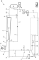
Figure 1 is a schematic diagram representing an installation according to one example embodiment of the disclosure, and -
Figure 2 is a schematic diagram representing an installation according to another example embodiment of the disclosure. - In the figures, the arrows represent without distinction the material flows of a method according to the disclosure, and the pipes, or pipe systems, that convey these flows in an installation according to the disclosure.
- With reference to
Figure 1 , a gas production ortreatment installation 10 for producing or treating an industrial gas is described. - The industrial gas may comprise, for example, LPG, ethylene, anthropogenic CO2, or any other industrial gas known per se.
- The
installation 10 is for example on land. By way of a variant, theinstallation 10 may comprise, for example, an FPSO. Generally, a Floating Production Storage and Offloading (FPSO) vessel may include a floating vessel that acts as a mobile offshore production and storage facility equipped with processing equipment for the separation, storage and offloading of hydrocarbons. When such hydrocarbons are processed, they may be safely stored in the FPSO until it can be offloaded onto a tanker or a pipeline for transportation ashore. - In the representative example of
FIG. 1 , theinstallation 10 includes aplant 12 that is capable of producing or treating at least the said industrial gas, this plant being represented, in part, in the form of a plurality of heat-receivingunits plant 12 that, in its operation, receives heat to perform a component function. - In
FIG. 1 , the heat-receiving units heat source 22 that is preferably thermally independent from the heat-receiving units. The term "thermally independent" is used to indicate, for example, that the load rate of one of the heat-receivingunits 14 to 20 does not directly or appreciably influence the load rate of another. Additionally, the heat requirements of one may not be linked to the heat requirements of the others, nor to the availability of theheat source 22. Advantageously, the heat-receiving units have distinct and identifiable functions within theplant 12. - In this example, the heat-receiving
units plant 12 along a material flow path separately from another heat-receiving unit. The heat-receivingunits - In addition to the
plant 12, theinstallation 10 includes: acompression unit 24 that is capable of producing acompressed gas 26 from at least one workinggas 28,dividers 30 for dividing the compressed gas into a plurality of compressed gas streams 32, andheat exchangers 34 that are capable of performing heat exchanges respectively between thecompressed gas streams 32 and the heat-receivingunits 14 to 20, with the compressed gas streams releasing and transferring heat respectively to the heat-receiving units, and condensing so as to form a plurality of liquid streams 36. - The
installation 10 includes afluid expansion system 37 that is capable of expanding the liquid streams 36 in order to obtain one or more expanded stream(s) 40, and obtain an expandedstream 46 at a first expansion pressure P1. - In the example, the fluid expansion system 37includes a
first sub-system 38 that is capable of expanding the liquid streams 36 in order to obtain the one or more expandedstreams 40, and obtain a second expanded stream 42 that is at least partially liquid from the one or more expanded streams, the second expanded stream being at a second expansion pressure P2 that is greater than the first expansion pressure P1. Thefluid expansion system 37 includes asecond sub-system 44 that is capable of producing the expandedstream 46, the second sub-system being capable of expanding the second expanded stream 42. - The
installation 10 includes anevaporator 48 that is capable of evaporating the expandedstream 46, by heat exchange with at least the saidheat source 22, and of producing agas stream 50. - The
installation 10 includes, for example, aheat exchanger 52 that is capable of superheating thegas stream 50 by heat exchange with the second expanded stream 42 and of producing asuperheated gas 54, with the said workinggas 28 comprising at least the superheated gas. - By way of a variant, the
installation 10 does not include such anexchanger 52, and the workinggas 28 comprises at least thegas stream 50. - In the example, the
installation 10 includes aheat exchanger 56 that is capable of condensing at least afraction 58 of the compressedgas 26 by heat exchange with acoolant fluid 60 and of producing aliquid stream 62 that is intended to be sent either to thefirst subsystem 38 in order to be expanded therein, or to the inlet of thecompression unit 24 after at least one expansion. In the example, all the compressed gas flowing into theheat exchanger 56 is condensed, this compressed gas being a fraction or all of the compressedgas 26 exiting thecompression unit 24. This makes it possible to ensure the operating flexibility of theinstallation 10. - The
installation 10 includes, for example, astorage capacitor 64 in order to contain a portion of the workinggas 28, and advantageously agas source 66 that is capable of supplying a working gas make-up 68. Advantageously, theinstallation 10 includes a purge system (not represented) for purging the working fluid. - The
installation 10 is advantageously capable of expanding a flow representing afraction 70 of the compressedgas 26 and producing agas stream 72 that is intended to be sent to thestorage capacitor 64. For example, theinstallation 10 is capable of expanding a flow representing afraction 74 of the compressedgas 26 and producing astream 76 that is intended to be sent directly to thefirst sub-system 38 without passing through the heat-receivingunits 14 to 20, this being in order to ensure maximum operating flexibility. - The
installation 10 may include additional regulation and control systems which are not expressly shown. - In the
installation 10, the expansion of fluids is carried out in valves, turbines or any system known per se to the person skilled in the art, regardless of the representation thereof inFigure 1 . - For example, the working
gas 28 comprises, and according to one particular embodiment is, a hydrocarbon or a mixture of hydrocarbons, in particular ethane, propane, butane, pentane, isopentane and cyclopentane. - Advantageously, in one or more examples, in the event that the working
gas 28 comprises only one single hydrocarbon, the proportion thereof is at least 70% by mass. - Advantageously, in one or more examples, the mixture of hydrocarbons comprises, in a proportion of at least 70% by mass, of propane, butane, or a mixture of propane and butane. For example, the working gas comprises at least 80% by mass of butane.
- According to one or more other examples, the working
gas 28 comprises, at least 80% by mass, of CO2 or ammonia. According to one particular embodiment, the workinggas 28 is CO2 or ammonia. - In the example, the
plant 12 in addition includes twoadditional units units 14 to 20 and from theheat source 22, and that consume heat at a lower temperature level than the heat-receivingunits 14 to 20. - According to other variants that are not expressly shown but are within the scope of the disclosure, the
plant 12 includes only one of these two additional units, or at least three additional units. - Advantageously, the
plant 12 also comprises at least one otheradditional unit 82 that is thermally independent from the heat-receivingunits 14 to 20 and from theheat source 22, and that consumes heat at a lower temperature level than the twoadditional units - According to particular embodiments, the heat-receiving
units 14 to 20 are a distillation column or separation column reboiler, or more generally a heater for liquid, gas or a two-phase mixture. For example, the heat-receivingunits 14 to 20 are at least five in number. - The
heat source 22 is, for example, one referred to as a "waste" heat source, or simply a stream of water (not represented) to be cooled, this stream being capable of transferring its heat. - For example, the two
additional units - For example, the other
additional unit 82 is a feed gas preheater, or more generally a heater for liquid, gas or a two-phase mixture. - The
first subsystem 38 comprises, for example, afirst capacitor 84 that is capable of receiving the one or more expanded stream(s) 40 at the second expansion pressure P2. - The
second sub-system 44 comprises, for example, asecond capacitor 90 that is capable of receiving, in particular, an expanded stream 92 resulting from the expansion of the second expanded stream 42. - The
compression unit 24 comprises, for example, acompressor 93, advantageously a centrifugal compressor. Thecompression unit 24 comprises amain inlet 94 for the workinggas 28, anoutlet 96 for the compressedgas 26, and in the example twoadditional inlets first gas stream 102 and asecond gas stream 104 from thefirst capacitor 84 and thesecond capacitor 90 respectively. - The operation of the
installation 10 illustrates a method according to the disclosure and will hereinafter be described. In other words, theinstallation 10 is capable of operationally implementing this method according to the disclosure. - The working
gas 28 constitutes a working fluid which circulates in gaseous, liquid, or possibly two-phase form in a closed circuit 106 (with the exception of any eventual make-up and purging) formed by theinstallation 10. - According to one advantageous embodiment, the working
gas 28 is supplied by theplant 12 itself. - By way of a variant, the working
gas 28 originates from another source (not represented). - In a step a), the industrial gas is produced by the
plant 12. - In a step b), the compressed
gas 26 is obtained by compressing at least the workinggas 28 in thecompression unit 24. The workinggas 28 is, for example, at a pressure of 2 bar absolute and at 40°C. The compressedgas 26 is for example at 34 bar absolute and 150°C. - In a step c), the compressed
gas 26 is divided by thedividers 30 in order to obtain the plurality of compressed gas streams 32. - In a step d), the heat exchanges are respectively brought about between the plurality of
compressed gas streams 32 and the heat-receivingunits 14 to 20 in theexchangers 34, with the compressed gas streams releasing and transferring heat respectively to the heat-receiving units, and condensing so as to form the plurality of liquid streams 36. The liquid streams 36 are, for example, at approximately 33 bar absolute and 140°C. - In a step e), the liquid streams 36 are expanded in order to obtain the expanded
streams 40, and the expandedstream 46 is obtained at the first expansion pressure P1. The expandedstream 46 is, for example, at 2.2 bar absolute (first expansion pressure) and 18°C. - By way of a variant (not represented), the liquid streams 36 are combined together and expanded so as to form a single expanded stream (not represented).
- In the example, the step e) includes a sub-step e1), in which the liquid streams 36 are expanded in order to obtain the expanded
streams 40, and the second expanded stream 42 is obtained from the one or more expanded stream(s) 40 at the second expansion pressure P2. The second expansion pressure P2 is, for example, approximately 10 to 15 bar absolute. The step e) also includes a sub-step e2), in which the expandedstream 46 is obtained at the first expansion pressure P1, this obtaining of the stream comprising at least one expansion of the second expanded stream 42, for example in avalve 107. - In a step f), the expanded
stream 46 is vaporised in theevaporator 48 by heat exchange with theheat source 22, and thegas stream 50 is obtained. - For example, the
gas stream 50 is then superheated in theheat exchanger 52 by heat exchange with the second expanded stream 42, in order to obtain thesuperheated gas 54, for example at 40°C. - In a step h), the working
gas 28 is obtained from at least the gas stream 50 (possibly superheated), and is advantageously stored in thestorage capacitor 64. - Possibly, for at least a certain period of time, for example during the start-up of the
plant 12, or during a drop in the load of the production plant, at least thefraction 58 of the compressedgas 26 is condensed by heat exchange with thecoolant fluid 60 in order to obtain theliquid stream 62. This is carried out, for example, when the heat requirement of the heat-receivingunits 14 to 20 is less than a nominal requirement, corresponding to the quantity of heat that the compressedgas 26 could release and transfer by condensing completely. - According to a first possibility, in addition to or in substitution (by-passing) of the steps c), d), and sub-step e1), at least a
fraction 108 of theliquid stream 62 is expanded in order to obtain astream 110 at the second expansion pressure P2. The second expanded stream 42 used in implementation in the sub-step e2) is obtained at least from the saidstream 110. - The term "in substitution of" is used to indicate that the steps c), d) and sub-step e1) temporarily do not take place. The
exchangers 34 are then completely "by-passed" (as per accepted terminology). - According to a second possibility, in addition to or in substitution of the steps c), d), e), f) and g), at least a
fraction 112 of theliquid stream 62 is expanded in order to obtain astream 114. Thefraction 70 of the compressedgas 26 obtained in the step b) is expanded in order to obtain thegas stream 72. The workinggas 28 is obtained at least in part from the saidgas stream 72 and the saidstream 114. - By way of a variant or in addition, for at least a certain period of time, the
fraction 74 of the compressedgas 26 is expanded in order to produce thestream 76 that is sent directly to thefirst sub-system 38 without passing through the heat-receivingunits 14 to 20. - In the sub-step e1), in the example, the expanded
streams 40 are received in thefirst capacitor 84 at the second expansion pressure P2. The second expanded stream 42 is liquid and extracted at the bottom of thefirst capacitor 84. Afirst gas stream 116 is extracted at the top of thefirst capacitor 84, and for example is at 80-120°C. - In the example, the
first gas stream 116 is divided into at least twogas streams additional units liquid streams liquid streams second capacitor 90. - Optionally, in the step b), at least a
fraction 102 of thefirst gas stream 116 is compressed in thecompression unit 24 in order to obtain the compressedgas 26. For example, the totality of thefirst gas stream 116 is compressed if the twoadditional units - In the sub-step e2), the expansion of the second expanded stream 42 produces, for example, the expanded stream 92 that is received in the
second capacitor 90. Thesecond capacitor 90 is at a third expansion pressure P3, which lies between the first expansion pressure P1 and the second expansion pressure P2. - The third expansion pressure P3 is, for example, 5-6 bar absolute.
- For example, a first
liquid stream 126 is extracted at the bottom of thesecond capacitor 90, and asecond gas stream 128 is extracted at the top of the second capacitor, for example at a temperature of 30 to 60°C. At least aportion 130 of thesecond gas stream 128 transfers heat to the otheradditional unit 82 by condensing so as to form a second liquid stream 132. The firstliquid stream 126 and the second liquid stream 132 are expanded in order to obtain the expandedstream 46. - Optionally, in the step b), at least the
fraction 104 of thesecond gas stream 128 is compressed in order to obtain the compressedgas 26. For example, the totality of thesecond gas stream 128 is compressed if the otheradditional unit 82 does not require heat. - Thanks to the characteristic features described here above, the supply of heat to the heat-receiving
units 14 to 20, and possibly 78, 80, 82, does not necessitate either resorting to the combustion of hydrocarbons in furnaces or boilers, or to electric heating. The industrial gas produced or treated in theplant 12 is therefore at least in part decarbonised, while providing a good level of performance (efficiency). In fact, the heat produced and transferred to the heat-receiving units is produced with a high degree of efficiency: 1 MW of electricity consumed in thecompression unit 24 being able to supply up to 4 MW of thermal power produced and transferred to the heat-receiving units. The Coefficient of Performance (COP) is therefore around 4. - The method is also simple to implement in operation, thanks to the heat-receiving
units 14 to 20 and theheat source 22 being independent of each other. Advantageously, the steps b) to h) may be started up with a minimum heat demand on the part of the heat-receiving units, and in a manner that is not correlated with the start-up of the units of theplant 12. - The working fluid may advantageously be produced on site by the
plant 12. All of the equipment units used in operation in order to carry out the steps of the method are readily available and often already used individually in an industrial gas production or treatment plant. - The disclosure provides the means for supplying heat to numerous units, and potentially to the
entire plant 12, in a centralised manner. -
Figure 2 represents aninstallation 200 according to one other example embodiment of the disclosure. Theinstallation 200 is similar to theinstallation 10 represented inFigure 1 in certain respects. The similar elements therein bear the same numerical references and will not be described again. However, one difference is that, in theinstallation 200, theplant 12 includes, for example, only two heat-receiving units, or only two of the units thereof are supplied with heat by the working fluid circulating in thecircuit 106. - The
plant 12 may omit theunits Figure 1 , or these units do not receive heat from the working fluid and are therefore not represented. - The
installation 200 may include only thefirst subsystem 38, which is simplified, and may omit thesubsystem 37 shown inFigure 1 . - The
first sub-system 38 does not include thefirst capacitor 84, and for example is limited to twoexpansion valves - The
installation 200 does not include theheat exchanger 52 represented inFigure 1 . - The expanded
stream 46 is obtained, for example, directly after combining together the expandedstreams 40. The expandedstream 46 is, for example, a liquid or a two-phase stream (with a liquid phase and a gaseous phase). - For example, the entirety of the
liquid stream 62 derived from thefraction 58 of the compressedgas 26 may possibly be expanded in order to obtain thestream 114. - For example, it is not intended that the
fraction 74 of the compressed gas be expanded and sent directly to thefirst sub-system 38. - The
installation 200, although simplified, operates in a manner analogous to theinstallation 10 and offers similar advantages.
Claims (12)
- A method comprising:a) producing or treating an industrial gas by a plant (12) comprising a plurality of heat-receiving units (14, 16, 17, 18, 20) that are thermally independent from one another, the plant (12) comprising at least one heat source (22);b) obtaining a compressed gas (26) by compressing at least one working gas (28);c) dividing the compressed gas (26) in order to obtain a plurality of compressed gas streams (32);d) performing heat exchanges respectively between the plurality of compressed gas streams (32) and the heat-receiving units (14, 16, 17, 18, 20), the compressed gas streams (32) releasing and transferring heat respectively to the heat-receiving units (14, 16, 17, 18, 20), and the compressed gas streams (32) condensing so as to form a plurality of liquid streams (36);e) expanding the liquid streams (36) in order to obtain one or more expanded stream(s) (40), and obtaining an expanded stream (46) from at least the expanded streams (40), the expanded stream (46) being at a first expansion pressure;f) vaporizing the expanded stream (46) by heat exchange with at least said heat source (22), and obtaining a gas stream (50); andg) obtaining the working gas (28) from at least the gas stream (50).
- The method according to claim 1, wherein the working gas (28) comprises a hydrocarbon, a mixture of hydrocarbons, CO2, or ammonia.
- The method according to claim 1 or 2, wherein the heat-receiving units (14, 16, 17, 18, 20) are capable of heating a liquid, a gas or a two-phase mixture.
- The method according to any one of claims 1 to 3, wherein, for at least a certain period of time, at least a fraction (58) of the compressed gas (26) obtained in step b) is condensed by heat exchange with a coolant fluid (60) in order to obtain a liquid stream (62).
- The method according to claim 4, wherein :- in addition to or in substitution of steps c), d), e), f) and g), at least a fraction (112) of the said liquid stream (62) is expanded in order to obtain a stream (114), and a fraction (70) of the compressed gas (26) obtained in step b) is expanded in order to obtain a gas stream (72); and- the working gas (28) compressed in step b) is obtained at least in part from the said gas stream (72) and the said stream (114).
- The method according to any one of claims 4 or 5, wherein step e) includes:e1) expanding the liquid streams (36) in order to obtain the one or more expanded stream(s) (40), and obtaining a second expanded stream (42) which is at least partially liquid from the one or more expanded stream(s) (40), the second expanded stream (42) being at a second expansion pressure;e2) obtaining the expanded stream (46), with the first expansion pressure being lower than the second expansion pressure, obtaining of the expanded stream (46) comprising at least one expansion of the second expanded stream (42).
- The method according to claim 6, wherein, in addition to or in substitution of steps c), d), and sub-step e1), at least a fraction (108) of said liquid stream (62) is expanded in order to obtain an expanded stream (110) at the second expansion pressure, the second expanded stream (42) used in sub-step e2) being obtained at least from the said expanded stream (110).
- The method according to any one of claims 6 or 7, wherein :- the plant (12) comprises at least a first additional unit (78) that is thermally independent from the heat-receiving units (14, 16, 17, 18, 20) and from the heat source (22), the first additional unit (78) receiving heat at a lower temperature level than the heat-receiving units (14, 16, 17, 18, 20),- in sub-step e1), the one or more expanded stream(s) (40) are received in a first capacitor (84) at the second expansion pressure, the second expanded stream (42) being liquid and extracted at the bottom of the first capacitor (84), a first gas stream (116) being extracted at the top of the first capacitor (84), and- at least a portion (118) of the first gas stream (116) transfers heat to the first additional unit (78) by condensing so as to form a liquid stream (122).
- The method according to claim 8, wherein, in step b), at least a fraction (102) of the first gas stream (116) is compressed in order to obtain the compressed gas (26).
- The method according to any one of claims 6 to 9, wherein :- the plant (12) includes at least one second additional unit (82) that is thermally independent from the heat-receiving units (14, 16, 17, 18, 20), from the first additional unit (78) and from the heat source (22), the second additional unit (82) receiving heat at a lower temperature level than the first additional unit (78); and- in sub-step e2), the expansion of the second expanded stream (42) produces an expanded stream (92) that is received in a second capacitor (90), a first liquid stream (126) being extracted at the bottom of the second capacitor (90), a second gas stream (128) being extracted at the top of the second capacitor (90), at least a portion (130) of the second gas stream (128) transferring heat to the second additional unit (82) by condensing so as to form a second liquid stream (132), the first liquid stream (122) and the second liquid stream (132) being expanded in order to obtain the expanded stream (46).
- The method according to claim 10, wherein, in step b), at least a fraction (104) of the second gas stream (128) is compressed in order to obtain the compressed gas (26).
- An installation (10; 200) comprising:a) a plant (12) capable of producing or treating an industrial gas, the plant (12) comprising a plurality of heat-receiving units (14, 16, 17, 18, 20; 17, 18) that are thermally independent from one another, the plant (12) comprising at least one heat source (22);b) a compression unit (24) that is capable of producing a compressed gas (26) from at least one working gas (28);c) one or more dividers (30) that are capable of dividing the compressed gas (26) into a plurality of compressed gas streams (32);d) heat exchangers (34) adapted for performing heat exchanges respectively between the plurality of compressed gas streams (32) and the heat-receiving units (14, 16, 17, 18, 20; 17, 18), the compressed gas streams (32) releasing and transferring heat respectively to the heat-receiving units (14, 16, 17, 18, 20; 17, 18), and condensing so as to form a plurality of liquid streams (36);e) a fluid expansion system (37) that is capable of expanding the liquid streams (36) in order to obtain one or more expanded stream(s) (40), and obtain an expanded stream (46) from at least the expanded streams (40), the expanded stream (46) being at a first expansion pressure; andf) an evaporator (48) that is capable of vaporizing the expanded stream (46), by heat exchange with at least the said heat source (22), and of producing a gas stream (50);the installation (10; 200) being capable of obtaining the working fluid (28) from at least said gas stream (50).
Priority Applications (3)
| Application Number | Priority Date | Filing Date | Title |
|---|---|---|---|
| EP23306530.9A EP4524378A1 (en) | 2023-09-15 | 2023-09-15 | Method for the production or treatment of at least one industrial gas with high- efficiency centralised heat supply |
| AU2024341248A AU2024341248A1 (en) | 2023-09-15 | 2024-09-10 | Method for the production or treatment of at least one industrial gas with high- efficiency centralised heat supply |
| PCT/EP2024/025269 WO2025056192A1 (en) | 2023-09-15 | 2024-09-10 | Method for the production or treatment of at least one industrial gas with high- efficiency centralised heat supply |
Applications Claiming Priority (1)
| Application Number | Priority Date | Filing Date | Title |
|---|---|---|---|
| EP23306530.9A EP4524378A1 (en) | 2023-09-15 | 2023-09-15 | Method for the production or treatment of at least one industrial gas with high- efficiency centralised heat supply |
Publications (1)
| Publication Number | Publication Date |
|---|---|
| EP4524378A1 true EP4524378A1 (en) | 2025-03-19 |
Family
ID=88295928
Family Applications (1)
| Application Number | Title | Priority Date | Filing Date |
|---|---|---|---|
| EP23306530.9A Pending EP4524378A1 (en) | 2023-09-15 | 2023-09-15 | Method for the production or treatment of at least one industrial gas with high- efficiency centralised heat supply |
Country Status (3)
| Country | Link |
|---|---|
| EP (1) | EP4524378A1 (en) |
| AU (1) | AU2024341248A1 (en) |
| WO (1) | WO2025056192A1 (en) |
Citations (3)
| Publication number | Priority date | Publication date | Assignee | Title |
|---|---|---|---|---|
| US20100122551A1 (en) * | 2008-11-18 | 2010-05-20 | Air Products And Chemicals, Inc. | Liquefaction Method and System |
| US20140069117A1 (en) * | 2011-03-22 | 2014-03-13 | Daewoo Shipbuilding & Marine Engineering Co., Ltd. | Non-explosive mixed refrigerant for re-liquefying device in system for supplying fuel to high-pressure natural gas injection engine |
| EP2933183A1 (en) * | 2012-12-11 | 2015-10-21 | Daewoo Shipbuilding & Marine Engineering Co., Ltd. | Liquefied gas processing system for ship |
-
2023
- 2023-09-15 EP EP23306530.9A patent/EP4524378A1/en active Pending
-
2024
- 2024-09-10 WO PCT/EP2024/025269 patent/WO2025056192A1/en active Pending
- 2024-09-10 AU AU2024341248A patent/AU2024341248A1/en active Pending
Patent Citations (3)
| Publication number | Priority date | Publication date | Assignee | Title |
|---|---|---|---|---|
| US20100122551A1 (en) * | 2008-11-18 | 2010-05-20 | Air Products And Chemicals, Inc. | Liquefaction Method and System |
| US20140069117A1 (en) * | 2011-03-22 | 2014-03-13 | Daewoo Shipbuilding & Marine Engineering Co., Ltd. | Non-explosive mixed refrigerant for re-liquefying device in system for supplying fuel to high-pressure natural gas injection engine |
| EP2933183A1 (en) * | 2012-12-11 | 2015-10-21 | Daewoo Shipbuilding & Marine Engineering Co., Ltd. | Liquefied gas processing system for ship |
Also Published As
| Publication number | Publication date |
|---|---|
| AU2024341248A1 (en) | 2026-03-26 |
| WO2025056192A1 (en) | 2025-03-20 |
Similar Documents
| Publication | Publication Date | Title |
|---|---|---|
| CN101454608B (en) | Method for vaporizing and heating a cryogenic fluid | |
| KR101641394B1 (en) | Conversion of liquefied natural gas | |
| JP6002841B2 (en) | Natural gas liquefaction method including phase change | |
| US20170038008A1 (en) | Cold utilization system, energy system comprising cold utilization system, and method for utilizing cold utilization system | |
| US20120317997A1 (en) | Conversion of liquefied natural gas | |
| JP2011528094A5 (en) | ||
| JP6250519B2 (en) | Boil-off gas recovery system | |
| JP2022542137A (en) | Methods for recovering refrigeration energy associated with power generation or liquefaction of gas streams | |
| US20220186884A1 (en) | Recompressed transcritical cycle with vaporization in cryogenic or low-temperature applications, and/or with coolant fluid | |
| KR20080081436A (en) | Device and method for liquefaction re-liquefaction | |
| KR20260036450A (en) | fuel treatment system and ship having the same | |
| JP6429159B2 (en) | Boil-off gas recovery system | |
| JP7519995B2 (en) | Method for producing electrical and thermal energy in a power cycle using a fluid obtained from a mixture of LNG and LPG | |
| JP7050782B2 (en) | Organic Rankine cycle in cryogenic applications or frozen fluids | |
| AU2024341248A1 (en) | Method for the production or treatment of at least one industrial gas with high- efficiency centralised heat supply | |
| PL233789B1 (en) | Installation for storage of energy in condensed air, with the oxygen separation module | |
| US20200224967A1 (en) | Hydrocarbon Distillation | |
| JPS585598A (en) | Power recovering method from liquefied natural gas aiming at low-load stabilization | |
| JP6341523B2 (en) | Boil-off gas recovery system | |
| KR102934151B1 (en) | Cold and Hot Power Generation System for Performance Improvement of LNG Evaporation Apparatus | |
| JPS5938407B2 (en) | Operation method for power recovery from LNG | |
| JPS58106109A (en) | Power recovery method from LNG using a turbine | |
| JP7476355B2 (en) | Liquefied gas regasification method and system for ships | |
| PL236371B1 (en) | Installation for storage of energy in condensed air and for recovery of energy, with the steam cycle | |
| PL236372B1 (en) | Installation for storage of energy in condensed air and for recovery of energy, with the steam module |
Legal Events
| Date | Code | Title | Description |
|---|---|---|---|
| PUAI | Public reference made under article 153(3) epc to a published international application that has entered the european phase |
Free format text: ORIGINAL CODE: 0009012 |
|
| STAA | Information on the status of an ep patent application or granted ep patent |
Free format text: STATUS: THE APPLICATION HAS BEEN PUBLISHED |
|
| AK | Designated contracting states |
Kind code of ref document: A1 Designated state(s): AL AT BE BG CH CY CZ DE DK EE ES FI FR GB GR HR HU IE IS IT LI LT LU LV MC ME MK MT NL NO PL PT RO RS SE SI SK SM TR |
|
| STAA | Information on the status of an ep patent application or granted ep patent |
Free format text: STATUS: REQUEST FOR EXAMINATION WAS MADE |
|
| 17P | Request for examination filed |
Effective date: 20250717 |
|
| GRAP | Despatch of communication of intention to grant a patent |
Free format text: ORIGINAL CODE: EPIDOSNIGR1 |
|
| STAA | Information on the status of an ep patent application or granted ep patent |
Free format text: STATUS: GRANT OF PATENT IS INTENDED |
|
| INTG | Intention to grant announced |
Effective date: 20250829 |
|
| P01 | Opt-out of the competence of the unified patent court (upc) registered |
Free format text: CASE NUMBER: UPC_APP_8453_4524378/2025 Effective date: 20250930 |
|
| GRAJ | Information related to disapproval of communication of intention to grant by the applicant or resumption of examination proceedings by the epo deleted |
Free format text: ORIGINAL CODE: EPIDOSDIGR1 |
|
| STAA | Information on the status of an ep patent application or granted ep patent |
Free format text: STATUS: REQUEST FOR EXAMINATION WAS MADE |
|
| GRAP | Despatch of communication of intention to grant a patent |
Free format text: ORIGINAL CODE: EPIDOSNIGR1 |
|
| STAA | Information on the status of an ep patent application or granted ep patent |
Free format text: STATUS: GRANT OF PATENT IS INTENDED |
|
| INTC | Intention to grant announced (deleted) | ||
| INTG | Intention to grant announced |
Effective date: 20260121 |
|
| RAP3 | Party data changed (applicant data changed or rights of an application transferred) |
Owner name: TECHNIP ENERGIES FRANCE Owner name: TOTALENERGIES ONETECH |