EP4524370A1 - Anti-rotation feature for instrumentation of gas turbine engine - Google Patents
Anti-rotation feature for instrumentation of gas turbine engine Download PDFInfo
- Publication number
- EP4524370A1 EP4524370A1 EP24188683.7A EP24188683A EP4524370A1 EP 4524370 A1 EP4524370 A1 EP 4524370A1 EP 24188683 A EP24188683 A EP 24188683A EP 4524370 A1 EP4524370 A1 EP 4524370A1
- Authority
- EP
- European Patent Office
- Prior art keywords
- assembly
- component
- probe
- threaded
- stator
- Prior art date
- Legal status (The legal status is an assumption and is not a legal conclusion. Google has not performed a legal analysis and makes no representation as to the accuracy of the status listed.)
- Pending
Links
Images


Classifications
-
- F—MECHANICAL ENGINEERING; LIGHTING; HEATING; WEAPONS; BLASTING
- F01—MACHINES OR ENGINES IN GENERAL; ENGINE PLANTS IN GENERAL; STEAM ENGINES
- F01D—NON-POSITIVE DISPLACEMENT MACHINES OR ENGINES, e.g. STEAM TURBINES
- F01D17/00—Regulating or controlling by varying flow
- F01D17/02—Arrangement of sensing elements
-
- F—MECHANICAL ENGINEERING; LIGHTING; HEATING; WEAPONS; BLASTING
- F01—MACHINES OR ENGINES IN GENERAL; ENGINE PLANTS IN GENERAL; STEAM ENGINES
- F01D—NON-POSITIVE DISPLACEMENT MACHINES OR ENGINES, e.g. STEAM TURBINES
- F01D21/00—Shutting-down of machines or engines, e.g. in emergency; Regulating, controlling, or safety means not otherwise provided for
- F01D21/003—Arrangements for testing or measuring
-
- F—MECHANICAL ENGINEERING; LIGHTING; HEATING; WEAPONS; BLASTING
- F01—MACHINES OR ENGINES IN GENERAL; ENGINE PLANTS IN GENERAL; STEAM ENGINES
- F01D—NON-POSITIVE DISPLACEMENT MACHINES OR ENGINES, e.g. STEAM TURBINES
- F01D11/00—Preventing or minimising internal leakage of working-fluid, e.g. between stages
- F01D11/08—Preventing or minimising internal leakage of working-fluid, e.g. between stages for sealing space between rotor blade tips and stator
- F01D11/14—Adjusting or regulating tip-clearance, i.e. distance between rotor-blade tips and stator casing
-
- F—MECHANICAL ENGINEERING; LIGHTING; HEATING; WEAPONS; BLASTING
- F01—MACHINES OR ENGINES IN GENERAL; ENGINE PLANTS IN GENERAL; STEAM ENGINES
- F01D—NON-POSITIVE DISPLACEMENT MACHINES OR ENGINES, e.g. STEAM TURBINES
- F01D25/00—Component parts, details, or accessories, not provided for in, or of interest apart from, other groups
- F01D25/24—Casings; Casing parts, e.g. diaphragms, casing fastenings
- F01D25/243—Flange connections; Bolting arrangements
-
- F—MECHANICAL ENGINEERING; LIGHTING; HEATING; WEAPONS; BLASTING
- F01—MACHINES OR ENGINES IN GENERAL; ENGINE PLANTS IN GENERAL; STEAM ENGINES
- F01D—NON-POSITIVE DISPLACEMENT MACHINES OR ENGINES, e.g. STEAM TURBINES
- F01D9/00—Stators
- F01D9/06—Fluid supply conduits to nozzles or the like
- F01D9/065—Fluid supply or removal conduits traversing the working fluid flow, e.g. for lubrication-, cooling-, or sealing fluids
-
- F—MECHANICAL ENGINEERING; LIGHTING; HEATING; WEAPONS; BLASTING
- F05—INDEXING SCHEMES RELATING TO ENGINES OR PUMPS IN VARIOUS SUBCLASSES OF CLASSES F01-F04
- F05D—INDEXING SCHEME FOR ASPECTS RELATING TO NON-POSITIVE-DISPLACEMENT MACHINES OR ENGINES, GAS-TURBINES OR JET-PROPULSION PLANTS
- F05D2230/00—Manufacture
- F05D2230/60—Assembly methods
-
- F—MECHANICAL ENGINEERING; LIGHTING; HEATING; WEAPONS; BLASTING
- F05—INDEXING SCHEMES RELATING TO ENGINES OR PUMPS IN VARIOUS SUBCLASSES OF CLASSES F01-F04
- F05D—INDEXING SCHEME FOR ASPECTS RELATING TO NON-POSITIVE-DISPLACEMENT MACHINES OR ENGINES, GAS-TURBINES OR JET-PROPULSION PLANTS
- F05D2260/00—Function
- F05D2260/30—Retaining components in desired mutual position
- F05D2260/31—Retaining bolts or nuts
-
- F—MECHANICAL ENGINEERING; LIGHTING; HEATING; WEAPONS; BLASTING
- F05—INDEXING SCHEMES RELATING TO ENGINES OR PUMPS IN VARIOUS SUBCLASSES OF CLASSES F01-F04
- F05D—INDEXING SCHEME FOR ASPECTS RELATING TO NON-POSITIVE-DISPLACEMENT MACHINES OR ENGINES, GAS-TURBINES OR JET-PROPULSION PLANTS
- F05D2270/00—Control
- F05D2270/80—Devices generating input signals, e.g. transducers, sensors, cameras or strain gauges
-
- F—MECHANICAL ENGINEERING; LIGHTING; HEATING; WEAPONS; BLASTING
- F05—INDEXING SCHEMES RELATING TO ENGINES OR PUMPS IN VARIOUS SUBCLASSES OF CLASSES F01-F04
- F05D—INDEXING SCHEME FOR ASPECTS RELATING TO NON-POSITIVE-DISPLACEMENT MACHINES OR ENGINES, GAS-TURBINES OR JET-PROPULSION PLANTS
- F05D2270/00—Control
- F05D2270/80—Devices generating input signals, e.g. transducers, sensors, cameras or strain gauges
- F05D2270/821—Displacement measuring means, e.g. inductive
Definitions
- the present invention pertains to the art of gas turbine engines, and more particularly to data collection during operation of a gas turbine engine.
- Testing of operation of gas turbine engines requires the collection of data regarding various components and locations on the gas turbine engine. This data collection often includes the measurement of clearances between components during operation of the gas turbine engine, or other features.
- the data is typically gathered via probes or other sensors arrayed about the engine and secured to rotationally fixed components of the engine. Many such sensors are secured in place by a threaded connection to the fixed structure, and it is desired to rotationally secure the sensors in place thus preventing their movement or “backing out” during operation of the engine. Further, the sensors may have brittle or otherwise delicate components, so the rotational securing must be accomplished without damaging the sensor.
- a component assembly of a gas turbine engine e.g., a stator assembly of a gas turbine engine
- a component of a gas turbine engine e.g., a stator
- an instrumentation probe installed to (e.g., installed in or mounted to) the component.
- the instrumentation probe includes a sensor assembly or a sensor body extending through a component wall of the component, and a threaded fastener installed onto a complementary thread of the sensor assembly or sensor body to retain the sensor assembly or sensor body at the component (e.g., in or at the component wall).
- the threaded fastener is retained to the sensor assembly or sensor body via deforming a threaded interface between the threaded fastener and the sensor assembly or sensor body.
- the deformation may be formed via application of a vibra-stake tool to the threaded interface.
- the deforming may be at one or more of the threaded fastener and the sensor body.
- the deformation may be achieved via application of a vibra-stake tool to the threaded interface.
- a housing may be installed to at least partially enclose the threaded interface.
- a cover may be installed onto the housing after deformation of the threaded interface.
- a probe lead may be operably connected to the sensor assembly and may be routed through a lead opening in the housing.
- the threaded fastener may be a nut.
- the threaded interface may be deformed at one or more circumferential locations about the threaded interface.
- a stator assembly of a gas turbine engine includes a stator having one or more stator vanes, and an instrumentation probe installed to (e.g., installed in or mounted to) the stator.
- the instrumentation probe includes a sensor assembly or sensor body extending through a stator wall of the stator, and a threaded fastener installed onto a complementary thread of the sensor assembly or sensor body to retain the sensor assembly or sensor body at the stator (e.g., in or at the stator wall).
- the threaded fastener is retained to the sensor assembly via deforming a threaded interface between the threaded fastener and the sensor assembly or sensor body.
- the deformation may be formed via application of a vibra-stake tool to the threaded interface.
- the threaded fastener may be a nut.
- a probe lead may be operably connected to the sensor body and may extend through a lead opening in the probe housing.
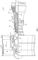
- FIG. 1 schematically illustrates a gas turbine engine 20.
- the gas turbine engine 20 is disclosed herein as a two-spool turbofan that generally incorporates a fan section 22, a compressor section 24, a combustor section 26 and a turbine section 28.
- Alternative engines might include other systems or features.
- the fan section 22 drives air along a bypass flow path B in a bypass duct, while the compressor section 24 drives air along a core flow path C for compression and communication into the combustor section 26 then expansion through the turbine section 28.
- FIG. 1 schematically illustrates a gas turbine engine 20.
- the gas turbine engine 20 is disclosed herein as a two-spool turbofan that generally incorporates a fan section 22, a compressor section 24, a combustor section 26 and a turbine section 28.
- Alternative engines might include other systems or features.
- the fan section 22 drives air along a bypass flow path B in a bypass duct
- the compressor section 24 drives air along a core flow path C for compression and communication into the combustor section 26
- the exemplary engine 20 generally includes a low speed spool 30 and a high speed spool 32 mounted for rotation about an engine central longitudinal axis A relative to an engine static structure 36 via several bearing systems 38. It should be understood that various bearing systems 38 at various locations may alternatively or additionally be provided, and the location of bearing systems 38 may be varied as appropriate to the application.
- the low speed spool 30 generally includes an inner shaft 40 that interconnects a fan 42, a low pressure compressor 44 and a low pressure turbine 46.
- the inner shaft 40 is connected to the fan 42 through a speed change mechanism, which in exemplary gas turbine engine 20 is illustrated as a geared architecture 48 to drive the fan 42 at a lower speed than the low speed spool 30.
- the high speed spool 32 includes an outer shaft 50 that interconnects a high pressure compressor 52 and high pressure turbine 54.
- a combustor 56 is arranged in exemplary gas turbine 20 between the high pressure compressor 52 and the high pressure turbine 54.
- An engine static structure 36 is arranged generally between the high pressure turbine 54 and the low pressure turbine 46.
- the engine static structure 36 further supports bearing systems 38 in the turbine section 28.
- the inner shaft 40 and the outer shaft 50 are concentric and rotate via bearing systems 38 about the engine central longitudinal axis A which is collinear with their longitudinal axes.
- each of the positions of the fan section 22, compressor section 24, combustor section 26, turbine section 28, and fan drive gear system 48 may be varied.
- gear system 48 may be located aft of combustor section 26 or even aft of turbine section 28, and fan section 22 may be positioned forward or aft of the location of gear system 48.
- Low pressure turbine 46 pressure ratio is pressure measured prior to inlet of low pressure turbine 46 as related to the pressure at the outlet of the low pressure turbine 46 prior to an exhaust nozzle.
- the geared architecture 48 may be an epicycle gear train, such as a planetary gear system or other gear system, with a gear reduction ratio of greater than about 2.3:1. It should be understood, however, that the above parameters are only exemplary of one embodiment of a geared architecture engine and that the invention is applicable to other gas turbine engines including direct drive turbofans.
- the fan section 22 of the engine 20 is designed for a particular flight condition--typically cruise at about 0.8Mach and about 35,000 feet (10,688 meters).
- 'TSFC' Thrust Specific Fuel Consumption
- Low fan pressure ratio is the pressure ratio across the fan blade alone, without a Fan Exit Guide Vane (“FEGV”) system.
- the low fan pressure ratio as disclosed herein according to one non-limiting embodiment is less than about 1.45.
- Low corrected fan tip speed is the actual fan tip speed in ft/sec divided by an industry standard temperature correction of [(Tram °R)/(518.7 °R)] 0.5 .
- the "Low corrected fan tip speed” as disclosed herein according to one non-limiting embodiment is less than about 1150 ft/second (350.5 m/sec).
- a signal lead such as a wire 84 is connected to the sensor body 66 at or near the threaded end 80 to transmit signals obtained at the sensor head 82 away from the instrumentation probe 62 toward, for example, a signal processor 86.
- a housing 88 is installed over the threaded end 80.
- the housing 88 is generally tubular having a first housing end 90 and a second housing end 92 and a sidewall 94 extending between the first housing end 90 and the second housing end 92.
- the wire 84 extends through a wire opening 96 in the sidewall 94.
- a removable cover 97 is installed to the housing 88 at the first housing end 90.
- the position of the nut 78 relative to the threaded end 80 is maintained by locking the relative position via a vibra-stake operation applied across the interface between the threaded end 80 and the nut 78 at one or more circumferential locations, for example, four circumferential locations as illustrated in FIG. 4 .
- FIGs. 5 and 6 Another embodiment of instrumentation probe 62 is illustrated in FIGs. 5 and 6 .
- the instrumentation probe 62 is installed directly to a component of the gas turbine engine 20, such as a case 102.
- the instrumentation probe 62 includes a probe head 104 disposed at a first side 106 of a case opening 108 in the case 102, and a probe body 110 that extends through the case opening 108.
- the probe body 110 includes a threaded end 112 that, when the instrumentation probe 62 is installed through the case opening 108, is disposed at a second side 114 of the case opening 108 opposite the first side 106.
- An installation collar 116 including internal threads 118 is installed onto the external threads of the threaded end 112 to retain the instrumentation probe 62 in the case opening 108. To maintain the position of the installation collar 116 relative to the threaded end 112, the threaded interface is deformed via the vibra-stake tool 98.
Landscapes
- Engineering & Computer Science (AREA)
- Mechanical Engineering (AREA)
- General Engineering & Computer Science (AREA)
- Physics & Mathematics (AREA)
- Fluid Mechanics (AREA)
- Structures Of Non-Positive Displacement Pumps (AREA)
Abstract
A a gas turbine engine includes a component of a gas turbine engine and an instrumentation probe (62) installed to the component. The instrumentation probe (62) includes a sensor body (66) extending through a component wall (100), and a threaded fastener (78) installed onto a complementary thread of the sensor body (66) to retain the sensor body (66). The threaded fastener (78) is retained to the sensor body (66) via deforming a threaded interface between the threaded fastener (78) and the sensor body (66).
Description
- The present invention pertains to the art of gas turbine engines, and more particularly to data collection during operation of a gas turbine engine.
- Testing of operation of gas turbine engines requires the collection of data regarding various components and locations on the gas turbine engine. This data collection often includes the measurement of clearances between components during operation of the gas turbine engine, or other features. The data is typically gathered via probes or other sensors arrayed about the engine and secured to rotationally fixed components of the engine. Many such sensors are secured in place by a threaded connection to the fixed structure, and it is desired to rotationally secure the sensors in place thus preventing their movement or "backing out" during operation of the engine. Further, the sensors may have brittle or otherwise delicate components, so the rotational securing must be accomplished without damaging the sensor.
- One such location for the measurement of clearances is radial proximity between stator segments and a rotating hub.
- In one aspect of the invention, a component assembly of a gas turbine engine (e.g., a stator assembly of a gas turbine engine),includes a component of a gas turbine engine (e.g., a stator), and an instrumentation probe installed to (e.g., installed in or mounted to) the component. The instrumentation probe includes a sensor assembly or a sensor body extending through a component wall of the component, and a threaded fastener installed onto a complementary thread of the sensor assembly or sensor body to retain the sensor assembly or sensor body at the component (e.g., in or at the component wall). The threaded fastener is retained to the sensor assembly or sensor body via deforming a threaded interface between the threaded fastener and the sensor assembly or sensor body.
- In any of the aspects or embodiments described above and herein, the deformation may be formed via application of a vibra-stake tool to the threaded interface.
- In any of the aspects or embodiments described above and herein, the deforming may be at one or more of the threaded fastener and the sensor body.
- In any of the aspects or embodiments described above and herein, the threaded fastener may be a nut.
- In any of the aspects or embodiments described above and herein, a probe housing may at least partially enclose the sensor body and the threaded fastener.
- In any of the aspects or embodiments described above and herein, a probe lead may be operably connected to the sensor body and may extend through a lead opening in the probe housing.
- In any of the aspects or embodiments described above and herein, the deformation may be at one or more circumferential locations of the threaded interface.
- In any of the aspects or embodiments described above and herein, one or more insulators may be positioned radially between the probe body and the component wall.
- In another aspect of the invention, a method of installing an instrumentation probe to a component of a gas turbine engine includes installing a sensor assembly or sensor body of the instrumentation probe through a component wall of the component, securing a threaded fastener to a complementary thread of the sensor assembly or sensor body to retain the sensor assembly or sensor body at the component wall, and deforming a threaded interface between the threaded fastener and the sensor assembly or sensor body to prevent rotation of the threaded fastener relative to the sensor assembly or sensor body.
- In any of the aspects or embodiments described above and herein, the deformation may be achieved via application of a vibra-stake tool to the threaded interface.
- In any of the aspects or embodiments described above and herein, a housing may be installed to at least partially enclose the threaded interface.
- In any of the aspects or embodiments described above and herein, a cover may be installed onto the housing after deformation of the threaded interface.
- In any of the aspects or embodiments described above and herein, a probe lead may be operably connected to the sensor assembly and may be routed through a lead opening in the housing.
- In any of the aspects or embodiments described above and herein, the threaded fastener may be a nut.
- In any of the aspects or embodiments described above and herein, the threaded interface may be deformed at one or more circumferential locations about the threaded interface.
- In yet another aspect of the invention, a stator assembly of a gas turbine engine includes a stator having one or more stator vanes, and an instrumentation probe installed to (e.g., installed in or mounted to) the stator. The instrumentation probe includes a sensor assembly or sensor body extending through a stator wall of the stator, and a threaded fastener installed onto a complementary thread of the sensor assembly or sensor body to retain the sensor assembly or sensor body at the stator (e.g., in or at the stator wall). The threaded fastener is retained to the sensor assembly via deforming a threaded interface between the threaded fastener and the sensor assembly or sensor body.
- In any of the aspects or embodiments described above and herein, the deformation may be formed via application of a vibra-stake tool to the threaded interface.
- In any of the aspects or embodiments described above and herein the threaded fastener may be a nut.
- In any of the aspects or embodiments described above and herein, a probe housing may at least partially enclose the sensor assembly and the threaded fastener.
- In any of the aspects or embodiments described above and herein, a probe lead may be operably connected to the sensor body and may extend through a lead opening in the probe housing.
- The following descriptions should not be considered limiting in any way. With reference to the accompanying drawings, like elements are numbered alike:
-
FIG. 1 is a partial cross-sectional view of a gas turbine engine; -
FIG. 2 is a partial cross-sectional view of a high pressure compressor of a gas turbine engine; -
FIG. 3 is a partial illustration of an instrumentation probe installed to a component of a gas turbine engine; -
FIG. 4 is a schematic illustration of deformation of a threaded interface of an instrumentation probe installed to a component of a gas turbine engine; -
FIG. 5 is a partial cross-sectional view of another embodiment of an instrumentation probe installed to a component of a gas turbine engine; and -
FIG. 6 is a face view of the embodiment ofFIG. 5 . - A detailed description of one or more embodiments of the apparatus and method are presented herein by way of exemplification and not limitation with reference to the Figures.
-
FIG. 1 schematically illustrates agas turbine engine 20. Thegas turbine engine 20 is disclosed herein as a two-spool turbofan that generally incorporates afan section 22, acompressor section 24, acombustor section 26 and aturbine section 28. Alternative engines might include other systems or features. Thefan section 22 drives air along a bypass flow path B in a bypass duct, while thecompressor section 24 drives air along a core flow path C for compression and communication into thecombustor section 26 then expansion through theturbine section 28. Although depicted as a two-spool turbofan gas turbine engine in the disclosed non-limiting embodiment, it should be understood that the concepts described herein are not limited to use with two-spool turbofans as the teachings may be applied to other types of turbine engines including three-spool architectures. - The
exemplary engine 20 generally includes alow speed spool 30 and ahigh speed spool 32 mounted for rotation about an engine central longitudinal axis A relative to an enginestatic structure 36 viaseveral bearing systems 38. It should be understood thatvarious bearing systems 38 at various locations may alternatively or additionally be provided, and the location ofbearing systems 38 may be varied as appropriate to the application. - The
low speed spool 30 generally includes aninner shaft 40 that interconnects afan 42, alow pressure compressor 44 and alow pressure turbine 46. Theinner shaft 40 is connected to thefan 42 through a speed change mechanism, which in exemplarygas turbine engine 20 is illustrated as a gearedarchitecture 48 to drive thefan 42 at a lower speed than thelow speed spool 30. Thehigh speed spool 32 includes anouter shaft 50 that interconnects ahigh pressure compressor 52 andhigh pressure turbine 54. Acombustor 56 is arranged inexemplary gas turbine 20 between thehigh pressure compressor 52 and thehigh pressure turbine 54. An enginestatic structure 36 is arranged generally between thehigh pressure turbine 54 and thelow pressure turbine 46. The enginestatic structure 36 further supports bearingsystems 38 in theturbine section 28. Theinner shaft 40 and theouter shaft 50 are concentric and rotate viabearing systems 38 about the engine central longitudinal axis A which is collinear with their longitudinal axes. - The core airflow is compressed by the
low pressure compressor 44 then thehigh pressure compressor 52, mixed and burned with fuel in thecombustor 56, then expanded over thehigh pressure turbine 54 andlow pressure turbine 46. Theturbines low speed spool 30 andhigh speed spool 32 in response to the expansion. It will be appreciated that each of the positions of thefan section 22,compressor section 24,combustor section 26,turbine section 28, and fandrive gear system 48 may be varied. For example,gear system 48 may be located aft ofcombustor section 26 or even aft ofturbine section 28, andfan section 22 may be positioned forward or aft of the location ofgear system 48. - The
engine 20 in one example is a high-bypass geared aircraft engine. In a further example, theengine 20 bypass ratio is greater than about six (6), with an example embodiment being greater than about ten (10), the gearedarchitecture 48 is an epicyclic gear train, such as a planetary gear system or other gear system, with a gear reduction ratio of greater than about 2.3 and thelow pressure turbine 46 has a pressure ratio that is greater than about five. In one embodiment, theengine 20 bypass ratio is greater than about ten (10:1), the fan diameter is significantly larger than that of thelow pressure compressor 44, and thelow pressure turbine 46 has a pressure ratio that is greater than about five 5:1.Low pressure turbine 46 pressure ratio is pressure measured prior to inlet oflow pressure turbine 46 as related to the pressure at the outlet of thelow pressure turbine 46 prior to an exhaust nozzle. The gearedarchitecture 48 may be an epicycle gear train, such as a planetary gear system or other gear system, with a gear reduction ratio of greater than about 2.3:1. It should be understood, however, that the above parameters are only exemplary of one embodiment of a geared architecture engine and that the invention is applicable to other gas turbine engines including direct drive turbofans. - A significant amount of thrust is provided by the bypass flow B due to the high bypass ratio. The
fan section 22 of theengine 20 is designed for a particular flight condition--typically cruise at about 0.8Mach and about 35,000 feet (10,688 meters). The flight condition of 0.8 Mach and 35,000 ft (10,688 meters), with the engine at its best fuel consumption--also known as "bucket cruise Thrust Specific Fuel Consumption ('TSFC')"--is the industry standard parameter of lbm of fuel being burned divided by lbf of thrust the engine produces at that minimum point. "Low fan pressure ratio" is the pressure ratio across the fan blade alone, without a Fan Exit Guide Vane ("FEGV") system. The low fan pressure ratio as disclosed herein according to one non-limiting embodiment is less than about 1.45. "Low corrected fan tip speed" is the actual fan tip speed in ft/sec divided by an industry standard temperature correction of [(Tram °R)/(518.7 °R)]0.5. The "Low corrected fan tip speed" as disclosed herein according to one non-limiting embodiment is less than about 1150 ft/second (350.5 m/sec). - Referring now to
FIG. 2 , illustrated is an embodiment of ahigh pressure compressor 52. Thehigh pressure compressor 52 includes one or more high pressure compressor (HPC)rotors 58 configured to rotate about the engine central longitudinal axis A, and one or more rotationally fixedHPC stators 60 located between axially adj acentHPC rotors 58. One or more instrumentation probes 62 are installed at theHPC stators 60 and may measure, for example, one or more of temperature, pressure or clearance. The instrumentation probes 62 extend through aprobe opening 64 in theHPC stators 60. While the invention is in the context of instrumentation probes 62 installed to theHPC stators 60, one skilled in the art will readily appreciate that the invention is applicable to other components and locations of thegas turbine engine 20. - Referring now to
FIG. 3 , an embodiment of aninstrumentation probe 62 includes asensor body 66 extending through theprobe opening 64, with alower insulator 68 positioned between thesensor body 66 and astator wall 100 at aninner stator surface 70, and similarly has anupper insulator 72 positioned between thesensor body 66 and thestator wall 100 at anouter stator surface 74. Aspacer 76 is placed on thesensor body 66 atop theupper insulator 72 and thesensor body 66 is secured in place in the probe opening 64 via anut 78 installed to a threadedend 80 of thesensor body 66, which results in a clamping force being applied between thenut 78 and asensor head 82 of thesensor body 66 on thestator 60. A signal lead, such as awire 84 is connected to thesensor body 66 at or near the threadedend 80 to transmit signals obtained at thesensor head 82 away from theinstrumentation probe 62 toward, for example, asignal processor 86. To protect the connection of thewire 84 to thesensor body 66, ahousing 88 is installed over the threadedend 80. In some embodiments, thehousing 88 is generally tubular having afirst housing end 90 and asecond housing end 92 and asidewall 94 extending between thefirst housing end 90 and thesecond housing end 92. In some embodiments, thewire 84 extends through awire opening 96 in thesidewall 94. Aremovable cover 97 is installed to thehousing 88 at thefirst housing end 90. - It is desired to ensure that the clamping force is maintained on the
stator 60 so that the position of thesensor body 66 is maintained during assembly and operation of thegas turbine engine 20. To accomplish this, the position of thenut 78 relative to the threadedend 80 is maintained by locking the relative position via a vibra-stake operation applied across the interface between the threadedend 80 and thenut 78 at one or more circumferential locations, for example, four circumferential locations as illustrated inFIG. 4 . The vibra-stake operation utilizes, for example, a vibra-stake tool or other engraving tool, shown schematically at 98, with a carbide tip to deform the interface between the threadedend 80 and thenut 78, in particular deforming the threads of the threadedend 80 and thenut 78. The deformation prevents rotation of thenut 78 relative to the threadedend 80 thus preventing loosening of the retention of thesensor body 66 in thestator 60. Use of the vibra-stake tool 98 to deform the interface allows for retention of thesensor body 66 greatly increases the break torque of the interface, without imparting a high level of force on theprobe 62 components thus preventing damage todelicate probe 62 components, such as thelower insulator 68 and theupper insulator 72. - Another embodiment of
instrumentation probe 62 is illustrated inFIGs. 5 and 6 . Theinstrumentation probe 62 is installed directly to a component of thegas turbine engine 20, such as acase 102. Theinstrumentation probe 62 includes aprobe head 104 disposed at afirst side 106 of a case opening 108 in thecase 102, and aprobe body 110 that extends through thecase opening 108. Theprobe body 110 includes a threadedend 112 that, when theinstrumentation probe 62 is installed through the case opening 108, is disposed at asecond side 114 of the case opening 108 opposite thefirst side 106. Aninstallation collar 116 includinginternal threads 118 is installed onto the external threads of the threadedend 112 to retain theinstrumentation probe 62 in thecase opening 108. To maintain the position of theinstallation collar 116 relative to the threadedend 112, the threaded interface is deformed via the vibra-stake tool 98. - The term "about" is intended to include the degree of error associated with measurement of the particular quantity based upon the equipment available at the time of filing the application. For example, "about" can include a range of ± 8% or 5%, or 2% of a given value.
- The terminology used herein is for the purpose of describing particular embodiments only and is not intended to be limiting of the invention. As used herein, the singular forms "a", "an" and "the" are intended to include the plural forms as well, unless the context clearly indicates otherwise. It will be further understood that the terms "comprises" and/or "comprising," when used in this specification, specify the presence of stated features, integers, steps, operations, elements, and/or components, but do not preclude the presence or addition of one or more other features, integers, steps, operations, element components, and/or groups thereof.
- While the invention has been described with reference to an exemplary embodiment or embodiments, it will be understood by those skilled in the art that various changes may be made and equivalents may be substituted for elements thereof without departing from the scope of the claims. In addition, many modifications may be made to adapt a particular situation or material to the teachings of the invention without departing from the essential scope thereof. Therefore, it is intended that the invention not be limited to the particular embodiment disclosed as the best mode contemplated for carrying out this invention, but that the invention will include all embodiments falling within the scope of the claims.
Claims (15)
- A component assembly of a gas turbine engine (20), the component assembly comprising:a component (60) of a gas turbine engine (20); andan instrumentation probe (62) installed to the component (60), the instrumentation probe (62) including:a sensor body (66) extending through a component wall (100) of the component (60); anda threaded fastener (78) installed onto a complementary thread (80) of the sensor body (66) to retain the sensor body (66) at the component (60), wherein the threaded fastener (78) is retained to the sensor body (66) by a deformed threaded interface between the threaded fastener (78) and the sensor body (66).
- The component assembly of claim 1, wherein the deformed threaded interface comprises deformation of the threaded fastener (78) and/or the sensor body (66).
- The component assembly of claim 1 or 2, comprising a probe housing (88) at least partially enclosing the sensor body (66) and the threaded fastener (78).
- The component assembly of claim 3, comprising a probe lead (84) operably connected to the sensor body (66) and extending through a lead opening (96) in the probe housing (88).
- The component assembly of any preceding claim, wherein the deformed threaded interface comprises deformation is at one or more circumferential locations of the threaded interface.
- The component assembly of any preceding claim, further comprising one or more insulators disposed radially between the probe body (110) and the component wall.
- A stator assembly of a gas turbine engine (20), comprising:a stator (60) having one or more stator vanes; andan instrumentation probe (62) installed to the stator (60), the instrumentation probe (62) including:a sensor assembly (66) extending through a stator wall (100) of the stator (60); anda threaded fastener (78) installed onto a complementary thread of the sensor assembly (66) to retain the sensor assembly at the stator (60), wherein the threaded fastener (78) is retained to the sensor assembly (66) by a deformed threaded interface between the threaded fastener (78) and the sensor assembly (66).
- The component assembly or the stator assembly of any preceding claim, wherein the deformation is formed via application of a vibra-stake tool (98) to the threaded interface.
- The stator assembly of claim 7 or 8, comprising a probe housing (88) at least partially enclosing the sensor assembly (66) and the threaded fastener (78), wherein, optionally, the stator assembly comprises a probe lead (84) operably connected to the sensor assembly (66) and extending through a lead opening (96) in the probe housing (88).
- A method of installing an instrumentation probe (62) to a component (60) of a gas turbine engine (20), the method comprising:installing a sensor assembly (66) of the instrumentation probe (62) through a component wall (100) of the component (60);securing a threaded fastener (78) to a complementary thread of the sensor assembly (66) to retain the sensor assembly (66) at the component wall (100); anddeforming a threaded interface between the threaded fastener (78) and the sensor assembly (66) to prevent rotation of the threaded fastener (78) relative to the sensor assembly (66).
- The method of claim 10, wherein the step of deforming comprises application of a vibra-stake tool (98) to the threaded interface.
- The method of claim 10 or 11, comprising installing a housing (88) to at least partially enclose the threaded interface.
- The method of claim 12, comprising:installing a cover (97) onto the housing (88) after deformation of the threaded interface; and/orrouting a probe lead (84) operably connected to the sensor assembly (66) through a lead opening (96) in the housing (88).
- The component assembly, the stator assembly or the method of any preceding claim, wherein the threaded fastener (78) is a nut (78).
- The method of any of claims 10 to 14, wherein the step of deforming comprises deforming the threaded interface at one or more circumferential locations about the threaded interface.
Applications Claiming Priority (1)
| Application Number | Priority Date | Filing Date | Title |
|---|---|---|---|
| US18/468,297 US12421866B2 (en) | 2023-09-15 | 2023-09-15 | Anti-rotation feature for instrumentation of gas turbine engine |
Publications (1)
| Publication Number | Publication Date |
|---|---|
| EP4524370A1 true EP4524370A1 (en) | 2025-03-19 |
Family
ID=91950125
Family Applications (1)
| Application Number | Title | Priority Date | Filing Date |
|---|---|---|---|
| EP24188683.7A Pending EP4524370A1 (en) | 2023-09-15 | 2024-07-15 | Anti-rotation feature for instrumentation of gas turbine engine |
Country Status (2)
| Country | Link |
|---|---|
| US (1) | US12421866B2 (en) |
| EP (1) | EP4524370A1 (en) |
Citations (3)
| Publication number | Priority date | Publication date | Assignee | Title |
|---|---|---|---|---|
| US20160061638A1 (en) * | 2014-09-02 | 2016-03-03 | General Electric Company | Fitting for positioning a probe in a hot gas path of a gas turbine engine |
| US20160265381A1 (en) * | 2013-10-18 | 2016-09-15 | United Technologies Corporation | Integrated gas turbine engine support and sensor |
| US20190383594A1 (en) * | 2018-06-19 | 2019-12-19 | United Technologies Corporation | Systems and methods for pseudo-triaxial capacitance probe assemblies |
Family Cites Families (8)
| Publication number | Priority date | Publication date | Assignee | Title |
|---|---|---|---|---|
| US3335598A (en) | 1964-10-28 | 1967-08-15 | American Motors Corp | Staking device |
| US4018083A (en) * | 1975-08-22 | 1977-04-19 | General Electric Company | Vibration detection probe holder |
| US4105058A (en) | 1977-03-31 | 1978-08-08 | Ball Valve Company, Inc. | Screw locking arrangement |
| US20100143031A1 (en) * | 2009-03-03 | 2010-06-10 | Remy Technologies, L.L.C. | Mechanical fastener having a thread staking mechanism |
| US8922203B2 (en) * | 2012-01-16 | 2014-12-30 | General Electric Company | Turbomachine blade monitoring system |
| CN102767556A (en) | 2012-07-18 | 2012-11-07 | 西安航空制动科技有限公司 | Punched point anti-loosening method for sunk screw connection |
| US9316479B2 (en) * | 2012-09-20 | 2016-04-19 | United Technologies Corporation | Capacitance based clearance probe and housing |
| US10598208B2 (en) * | 2017-05-15 | 2020-03-24 | Toyota Motor Engineering & Manufacturing North America, Inc. | Hammer-operated indentation tool |
-
2023
- 2023-09-15 US US18/468,297 patent/US12421866B2/en active Active
-
2024
- 2024-07-15 EP EP24188683.7A patent/EP4524370A1/en active Pending
Patent Citations (3)
| Publication number | Priority date | Publication date | Assignee | Title |
|---|---|---|---|---|
| US20160265381A1 (en) * | 2013-10-18 | 2016-09-15 | United Technologies Corporation | Integrated gas turbine engine support and sensor |
| US20160061638A1 (en) * | 2014-09-02 | 2016-03-03 | General Electric Company | Fitting for positioning a probe in a hot gas path of a gas turbine engine |
| US20190383594A1 (en) * | 2018-06-19 | 2019-12-19 | United Technologies Corporation | Systems and methods for pseudo-triaxial capacitance probe assemblies |
Also Published As
| Publication number | Publication date |
|---|---|
| US20250092798A1 (en) | 2025-03-20 |
| US12421866B2 (en) | 2025-09-23 |
Similar Documents
| Publication | Publication Date | Title |
|---|---|---|
| EP3453844B1 (en) | Low profile embedded blade tip clearance sensor | |
| US11441444B2 (en) | Electrical resistance wear indicator | |
| US10436732B2 (en) | Near full hoop electrical axial shift wear indication sensor | |
| EP3760838B1 (en) | Gas turbine variable vane system and method | |
| US11053798B2 (en) | Gas turbine engine having a trim balance | |
| WO2015057549A1 (en) | Integrated gas turbine engine support and sensor | |
| EP3929408A1 (en) | Improved rotating bearing centering spring for a gas turbine | |
| US12421866B2 (en) | Anti-rotation feature for instrumentation of gas turbine engine | |
| EP3431716B1 (en) | Variable-pitch vane assembly and corresponding assembly method | |
| US11286797B2 (en) | Gas turbine engine stator vane base shape | |
| US11624294B1 (en) | Restraining plug | |
| EP3933170B1 (en) | Mid mount sleeve arrangement | |
| US20200072072A1 (en) | Fixed vane pack retaining ring | |
| US20200056482A1 (en) | Dovetail weight system for rotor balance | |
| EP3453837B1 (en) | Fan exit stator assembly retention system | |
| EP4520926A1 (en) | Clearance measurement between seal elements of a gas turbine engine | |
| EP3967862A1 (en) | Speed sensor probe location in gas turbine engine | |
| EP4488494B1 (en) | Bearing inner race with sleeve and integrated puller | |
| US12352180B2 (en) | Compressor rotor destacking apparatus and method | |
| EP3428404B1 (en) | Stator vane assembly for a gas turbine engine | |
| EP4428342A1 (en) | Bolted joint of gas turbine engine | |
| EP3415905B1 (en) | Vibration induced noise suppression device |
Legal Events
| Date | Code | Title | Description |
|---|---|---|---|
| PUAI | Public reference made under article 153(3) epc to a published international application that has entered the european phase |
Free format text: ORIGINAL CODE: 0009012 |
|
| STAA | Information on the status of an ep patent application or granted ep patent |
Free format text: STATUS: THE APPLICATION HAS BEEN PUBLISHED |
|
| AK | Designated contracting states |
Kind code of ref document: A1 Designated state(s): AL AT BE BG CH CY CZ DE DK EE ES FI FR GB GR HR HU IE IS IT LI LT LU LV MC ME MK MT NL NO PL PT RO RS SE SI SK SM TR |
|
| STAA | Information on the status of an ep patent application or granted ep patent |
Free format text: STATUS: REQUEST FOR EXAMINATION WAS MADE |
|
| 17P | Request for examination filed |
Effective date: 20250919 |