EP4524340A1 - The system and method to anchor flexible structural strips - Google Patents
The system and method to anchor flexible structural strips Download PDFInfo
- Publication number
- EP4524340A1 EP4524340A1 EP23197326.4A EP23197326A EP4524340A1 EP 4524340 A1 EP4524340 A1 EP 4524340A1 EP 23197326 A EP23197326 A EP 23197326A EP 4524340 A1 EP4524340 A1 EP 4524340A1
- Authority
- EP
- European Patent Office
- Prior art keywords
- flexible strip
- anchorage system
- anchorage
- support
- strip
- Prior art date
- Legal status (The legal status is an assumption and is not a legal conclusion. Google has not performed a legal analysis and makes no representation as to the accuracy of the status listed.)
- Withdrawn
Links
Images


Classifications
-
- E—FIXED CONSTRUCTIONS
- E04—BUILDING
- E04C—STRUCTURAL ELEMENTS; BUILDING MATERIALS
- E04C5/00—Reinforcing elements, e.g. for concrete; Auxiliary elements therefor
- E04C5/08—Members specially adapted to be used in prestressed constructions
- E04C5/12—Anchoring devices
-
- E—FIXED CONSTRUCTIONS
- E04—BUILDING
- E04C—STRUCTURAL ELEMENTS; BUILDING MATERIALS
- E04C5/00—Reinforcing elements, e.g. for concrete; Auxiliary elements therefor
- E04C5/07—Reinforcing elements of material other than metal, e.g. of glass, of plastics, or not exclusively made of metal
-
- E—FIXED CONSTRUCTIONS
- E04—BUILDING
- E04C—STRUCTURAL ELEMENTS; BUILDING MATERIALS
- E04C5/00—Reinforcing elements, e.g. for concrete; Auxiliary elements therefor
- E04C5/08—Members specially adapted to be used in prestressed constructions
- E04C5/085—Tensile members made of fiber reinforced plastics
Definitions
- the invention relates to structural and materials engineering fields and can fabricate and characterize structural composites, which employ flat flexible strips. Specifically, it discloses an anchoring system for flexible components made from reinforced plastics subjected to tension-the friction nature of the anchorage allows for minimizing the stress concentration at the outer gripping edge.
- the invention finds a crucial role in structural engineering. It significantly contributes to designing, analyzing, and assessing safe and robust structures incorporating fiber-reinforced plastic tension members.
- the anchorage system is a critical tool for verifying the reliability and effectiveness of tension members within complex structural systems.
- Tensioned elements made of composite materials particularly fiber-reinforced plastic (FRP) composites, offer numerous advantages, including corrosion resistance, high tensile strength, lightweight nature, flexibility, and cost-effectiveness. These attributes make them highly desirable for various applications due to their availability in customizable lengths and low installation costs.
- FRP fiber-reinforced plastic
- grips facilitate load transmission through the tensioned composite by inducing shear stresses on the material's surface. These stresses can arise due to micro-slipping of the composite strip within the anchorage system, generating frictional shear stresses.
- CFRP carbon fiber-reinforced polymers
- the patent application WO2018072589A1 introduces an automated control system for pre-tensioning bundled steel strands, enhancing efficiency and reducing labor costs. It incorporates a pre-tensioning device, an integrated tensioning device, and a control center, allowing synchronized tensioning of multiple steel strands.
- the system's integration minimizes the need for multiple pumping stations and control centers, enabling simultaneous pre-tensioning and integrated tensioning of pre-stressed strands.
- the patent LT6275B introduces fastening equipment for producing and testing tensile composite elements. It features symmetrical anchorage joints embracing reinforcement bars of structural components. Plates serve as permanent formwork, while tension devices measure deformation. Despite its merits, this invention primarily focuses on internal bars and ties within composite elements.
- the anchorage system of the present invention addresses the challenge of transmitting tensile loads to flexible strips made of composite materials. It utilizes a spiral surface on a flat disc to accommodate the flexible strip, gradually increasing shear stress along its surface through friction.
- the device eliminates stress concentration at the entry point, enhancing load transmission.
- FRP fiber-reinforced plastic
- CFRP carbon fiber-reinforced plastic
- the device is particularly effective with anisotropic materials like CFRP.
- the present invention relates to a novel anchorage system S, as shown in Fig. 1 , encompassing:
- the anchorage system of the present invention is characterized in that it efficiently transmits tensile loads onto flexible ribbon strips (5), thereby revolutionizing the manipulation of tension members constructed from fiber-reinforced plastic (FRP) flat strips.
- the invention presents a new anchorage system and outlines a method for applying force to these tension members.
- the invention's core is a two-part anchorage system S that interacts effectively with flexible strips 5.
- the first part features a carefully contoured spiral friction support 1 with a curved surface accommodating the flexible strip 5.
- This curvature has a unique characteristic: the curvature value is zero when the flexible strip 5 initially contacts the support 1.
- This design establishes an innovative interaction between the anchorage system S and the flexible strip 5, enhancing its functional efficiency.
- the gripping process relies on frictional forces generated between the tensioned flexible strip 5 and the curved surface of the support 1. This interaction results in micro-slippage across the curved surface, enabling the effective transmission of the applied load to the flexible strip 5.
- the device's architecture leverages friction to effectively transfer tensioning forces from the flexible strip 5, creating an efficient load transmission mechanism.
- the second part of the device complements the first by securely fastening the end of the flexible strip 5 emerging from a defined exit point.
- the second part envelops the first one, providing a seamless integration that improves the gripping process and stabilizes the flexible strip 5 during tension application.
- Two side plates 2 facilitate load transfer from a testing machine's power drive to the support 1.
- Bolts 3 fix the disk, ensuring stability during operation.
- Internal clamps 4 enhance the gripping process by clamping the inner end of the flexible strip 5 before applying tension force P, adding control to the mechanism.
- a strategically positioned hole 6 is an anchor point acting as a hinge aligning the contact surface of the support 1 at the entrance point 9 with the load P application line 10 because of dynamic loading effects and enhancing reliability in practical applications.
- Analytical model of the anchorage system S constitutes the simplified assumptions of constant friction coefficient, absolute rigidity of the support disc 1, and inextensible material of the flexural strip 5.
- Figure 2 sketches the distribution of the corresponding load components.
- point O determines the center of the planar curve; point O 1 defines the circle of curvature drawn at point L, in which radius ⁇ describes the curvature radius at L.
- the given equation permits us to define the traction coefficient, i.e., the ratio between the axial load upcoming to and incoming from the curved surface on the first part of the anchorage system S.
- P( ⁇ ) P, i.e., the design axial load.
- Figs. 3 and 4 illustrate the application examples of the proposed anchorage system S for a pedestrian stress-ribbon bridge prototype and 3D-printed grips for materials characterization of flexible strip.
Landscapes
- Engineering & Computer Science (AREA)
- Architecture (AREA)
- Civil Engineering (AREA)
- Structural Engineering (AREA)
- Reinforcement Elements For Buildings (AREA)
Abstract
The invention presents a novel anchorage system tailored for precise mechanical testing of fiber-reinforced plastic flat strips used as tension members. The device is pivotal in structural engineering, aiding the design, materials characterizing, and assessing durable structures, employing such tension members. Unlike existing solutions that exhibit stress concentrations, the innovative design ensures uniform load transmission by utilizing a curved disc with a unique curvature profile and a micro-slipping phenomenon based on friction. This eliminates the stress peaks and enhances the accuracy of mechanical testing. Comprising two main components, the device securely fastens and stabilizes the flexible strip, enabling controlled tension application. The invention's practical installation and internal clamping system further enhance its functionality. In industries like aerospace, automotive, and construction, where fiber-reinforced plastics are increasingly employed, this anchorage system plays a crucial role in ensuring the reliability and effectiveness of tension members in complex structures.
Description
- The invention relates to structural and materials engineering fields and can fabricate and characterize structural composites, which employ flat flexible strips. Specifically, it discloses an anchoring system for flexible components made from reinforced plastics subjected to tension-the friction nature of the anchorage allows for minimizing the stress concentration at the outer gripping edge.
- Within the broader engineering context, the invention finds a crucial role in structural engineering. It significantly contributes to designing, analyzing, and assessing safe and robust structures incorporating fiber-reinforced plastic tension members. The device's ability to accurately apply tensile forces to these materials without introducing artificial stress points aligns seamlessly with the demands of modern structural engineering. This innovative approach ensures that tension members' behavior can be thoroughly understood and optimized for real-world applications.
- Industries such as aerospace, automotive, construction, and manufacturing stand to benefit from this invention's advancements in structural engineering. As these sectors increasingly adopt fiber-reinforced plastic materials to enhance performance and durability, the anchorage system is a critical tool for verifying the reliability and effectiveness of tension members within complex structural systems.
- Tensioned elements made of composite materials, particularly fiber-reinforced plastic (FRP) composites, offer numerous advantages, including corrosion resistance, high tensile strength, lightweight nature, flexibility, and cost-effectiveness. These attributes make them highly desirable for various applications due to their availability in customizable lengths and low installation costs.
- The transmission of external loads to tensioned composite elements presents a significant challenge in their practical application and testing. To address this challenge, anchorages known as grips or gripping devices are utilized. These grips facilitate load transmission through the tensioned composite by inducing shear stresses on the material's surface. These stresses can arise due to micro-slipping of the composite strip within the anchorage system, generating frictional shear stresses.
- For effective load transmission, various anchoring techniques have been explored. The use of carbon fiber-reinforced polymers (CFRP) has gained attention in recent research, highlighted by the following studies:
- Mohee, F. M., Al-Mayah, A., & Plumtree, A. (2017). Development of a novel prestressing anchor for CFRP plates: Experimental investigations. Composite Structures, 176, 20-32.
- You, Y. C., Choi, K. S., & Kim, J. (2012). An experimental investigation on flexural behavior of RC beams strengthened with prestressed CFRP strips using a durable anchorage system. Composites Part B: Engineering, 43(8), 3026-3036.
- Correia, L., Teixeira, T., Michels, J., Almeida, J. A., & Sena-Cruz, J. (2015). Flexural behaviour of RC slabs strengthened with prestressed CFRP strips using different anchorage systems. Composites Part B: Engineering, 81, 158-170.
- Hosseini, A., Ghafoori, E., Motavalli, M., Nussbaumer, A., & Zhao, X. L. (2017). Mode I fatigue crack arrest in tensile steel members using prestressed CFRP plates. Composite Structures, 178, 119-134.
- Michels, J., Martinelli, E., Czaderski, C., & Motavalli, M. (2014). Prestressed CFRP strips with gradient anchorage for structural concrete retrofitting: Experiments and numerical modeling. Polymers, 6(1), 114-131.
- Hosseini, A., Ghafoori, E., Motavalli, M., Nussbaumer, A., Zhao, X. L., & Koller, R. (2018). Prestressed unbonded reinforcement system with multiple CFRP plates for fatigue strengthening of steel members. Polymers, 10(3), 264.
- CFRP materials, known for their strength and flexibility, have been employed in applications ranging from reinforcing old structures with cracks to enhancing concrete constructions using pre-stretched CFRP bands. Current techniques often involve anchoring CFRP elements with metal plates, achieving the desired reinforcement effects. However, existing methods primarily focus on single or parallel CFRP bands, and the anchoring systems might not provide uniformly distributed stress.
- The distribution of shear stresses during load transmission presents a challenge, resulting in stress concentration at the entry point of the anchorage system. This stress concentration has exceeded the average stress within the tensioned strip, leading to premature failure near the anchorage entry point. Achieving uniformly distributed stress across the tensioned strip is essential for determining its maximum load-carrying capacity and preventing premature failure.
- Existing patents have proposed solutions to mitigate shear stress concentration. The patent application
US2007221894A suggests inserting compliant interlayers between steel wedges and tensioned strips to reduce stiffness and frictional shear stresses. However, selecting appropriate interlayer materials that combine compliance with sufficient bearing resistance and shear strength remains challenging. Furthermore, manufacturing complexities and reusability issues hinder the practicality of these interlayers. - In recent developments, the patent application
WO2018072589A1 introduces an automated control system for pre-tensioning bundled steel strands, enhancing efficiency and reducing labor costs. It incorporates a pre-tensioning device, an integrated tensioning device, and a control center, allowing synchronized tensioning of multiple steel strands. The system's integration minimizes the need for multiple pumping stations and control centers, enabling simultaneous pre-tensioning and integrated tensioning of pre-stressed strands. - The patent
LT6275B - Another way to reduce the stress concentration at the anchor's entry is using wedge-shaped grips made of materials with variable stiffness, which increases in the direction away from the entry point. This way was described in the patent
US5713169B , entitled "Anchorage device for high-performance fiber composite cables". A cone element made of material with a minimum stiffness is located at the entry in the anchor, followed by another cone element of material with higher stiffness, and so on. This results in the flattening of the shear stress peak. - However, selecting materials, manufacturing the cone elements, and assembling the anchorage are labor-consuming. Moreover, the reliability of the compliant materials under high stress needs to be improved. Finally, by applying this method, the shear stress peak at the entry in the anchor may be reduced but could not be avoided.
- An anchorage system of variable rigidity is proposed in the patent application
US2004216403A entitled "The anchor for a strip-type tension member". The main idea is to divide clamping plates into segments connected by bridges of varying rigidity; the farther the part from the entry point, the higher the bridge's rigidity. - However, the construction is challenging to manufacture and assemble, whereas it only reduces the shear stress peak but only permits it partially.
- Thus, the existing solutions to the problem of load transmission on a tensioned high-strength CFRP strip partially solve this problem. They lead to an inevitable decrease in shear stress concentration, but the shear stress peak on the surface of the tensioned strip does not disappear completely. The character of shear stress distribution along a tensioned strip remains essentially the same - with maximum stress at the entry point in the anchorage system followed by their decrease farther away from the entry. Hence, the stress concentration at the entrance in anchorage, while decreased, remains. Moreover, applying adhesive or compliant interlayers in the anchorage system practically excludes the possibility of re-use the anchorage parts in immediate contact with the surface of the tensioned element.
- Therefore, there is a need for a simple anchorage system with no shear stress peak at the entry point.
- The anchorage system of the present invention addresses the challenge of transmitting tensile loads to flexible strips made of composite materials. It utilizes a spiral surface on a flat disc to accommodate the flexible strip, gradually increasing shear stress along its surface through friction. The device eliminates stress concentration at the entry point, enhancing load transmission. Made from materials like fiber-reinforced plastic (FRP) or carbon fiber-reinforced plastic (CFRP), the device is particularly effective with anisotropic materials like CFRP.
- Existing solutions partially reduce stress concentrations on tensioned strips, but stress peaks at entry points remain. This new anchorage system eliminates stress peaks, enhancing load transmission. Its innovative design overcomes challenges associated with shear stress concentration, ensuring more accurate mechanical testing of tension members.
- The following pictures are provided and referenced hereafter to understand the frictional fixture principle of a flexible FRP strip and appreciate its applications. Figures are given as examples only and in no way should limit the scope of the invention. The invention is explained in the drawings, wherein:
-
FIG. 1 depicts a schematic of the spiral anchorage device of a flexible flat strip; -
FIG. 2 depicts a schematic of load components acting on an elementary arc segment; -
FIG. 3 shows a theoretical application example of equipment fixing CFRP flexible strips of the pedestrian stress-ribbon bridge prototype; -
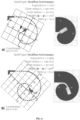
FIG. 4 shows laboratory application examples ensuring different traction coefficients χ of spiral surfaces manufactured from PLA using 3D printing technology and tested as anchors for CFRP strip: a) χ = 10; b) χ = 20. - The present invention relates to a novel anchorage system S, as shown in
Fig. 1 , encompassing: - 1. Spiral friction support;
- 2. A pair of plates to fix the support 1 and connect the system S to permanent support at
point 6; - 3. Bolts;
- 4. Internal clamps to pre-fix the
flexible strip 5 while activating the frictional force; - 5. The flexible strip;
- 6. A hole for fixing; remarkably, the hole aligns with the tensile load entrance vector P and ensures system S rotation by following the dynamic loading effects;
- 7. A possible layered structure of the spiral support 1. The various materials, e.g., plastic, steel, and concrete, and a combination thereof in
different layers 7 are applicable for constructing the spiral support 1; - 8. A slope of the spiral surface of the support 1 in contact with the
flexible strip 5; - 9. The zero-curvature entrance point of the
flexible strip 5 to the anchorage system S; - 10. The axial load P application line.
- The anchorage system of the present invention is characterized in that it efficiently transmits tensile loads onto flexible ribbon strips (5), thereby revolutionizing the manipulation of tension members constructed from fiber-reinforced plastic (FRP) flat strips. The invention presents a new anchorage system and outlines a method for applying force to these tension members. The invention's core is a two-part anchorage system S that interacts effectively with
flexible strips 5. The first part features a carefully contoured spiral friction support 1 with a curved surface accommodating theflexible strip 5. This curvature has a unique characteristic: the curvature value is zero when theflexible strip 5 initially contacts the support 1. This design establishes an innovative interaction between the anchorage system S and theflexible strip 5, enhancing its functional efficiency. - The gripping process relies on frictional forces generated between the tensioned
flexible strip 5 and the curved surface of the support 1. This interaction results in micro-slippage across the curved surface, enabling the effective transmission of the applied load to theflexible strip 5. The device's architecture leverages friction to effectively transfer tensioning forces from theflexible strip 5, creating an efficient load transmission mechanism. - The second part of the device complements the first by securely fastening the end of the
flexible strip 5 emerging from a defined exit point. The second part envelops the first one, providing a seamless integration that improves the gripping process and stabilizes theflexible strip 5 during tension application. - Practicality is a crucial consideration in this invention, evident in the straightforward installation process. Two
side plates 2 facilitate load transfer from a testing machine's power drive to the support 1.Bolts 3 fix the disk, ensuring stability during operation. Internal clamps 4 enhance the gripping process by clamping the inner end of theflexible strip 5 before applying tension force P, adding control to the mechanism. A strategically positionedhole 6 is an anchor point acting as a hinge aligning the contact surface of the support 1 at theentrance point 9 with the loadP application line 10 because of dynamic loading effects and enhancing reliability in practical applications. - Beyond its components, the invention's significance lies in its ability to manipulate tension flexural strips 5. The reliance on frictional forces and careful design result in the anchorage system S that addresses challenges in tension member manipulation.
- Analytical model of the anchorage system S. The analytical model constitutes the simplified assumptions of constant friction coefficient, absolute rigidity of the support disc 1, and inextensible material of the
flexural strip 5.Figure 2 sketches the distribution of the corresponding load components. In this scheme, point O determines the center of the planar curve; point O1 defines the circle of curvature drawn at point L, in which radius ρ describes the curvature radius at L. - The rate of the increase of the angle dθ for the segment length ds determines the curvature at L (
Fig. 2 ):
- The following equations define the equilibrium conditions of the elementary arc segment ds in the projections on the τ and n axes (
Fig. 2 ):


- The following equations determine the differential solution of the segment length ds and the radius ρ in the polar coordinate system O L = r(ϕ) and the corresponding traction ratio:


- The following equations describe a spiral in polar coordinates, its radius, and the corresponding traction ratio:


- The given equation permits us to define the traction coefficient, i.e., the ratio between the axial load upcoming to and incoming from the curved surface on the first part of the anchorage system S.
- Optimization model. For the rectangular cross-section of the flexible strip, the following condition determines the ultimate resistance of the CFRP strip:

- Following Eqn. 12, the bending effect increases with increasing the strip thickness t and elasticity modulus E of the
flexible strip 5; b is the width of thestrip 5.
The load-bearing capacity R of the internal clamps 4 determines the required traction ratio:
- The following equation accounts for the bending effect, describing the inner radius r 1 under the assumption of P(ϕ) = R:


- Eqn. 14 defines the required outer radius r 2 by assuming P(ϕ) = P, i.e., the design axial load. The following expression finalizes the optimization process, determining the exponent of the power function in Eqn. 9:

-
Figs. 3 and4 illustrate the application examples of the proposed anchorage system S for a pedestrian stress-ribbon bridge prototype and 3D-printed grips for materials characterization of flexible strip.
Claims (5)
- The anchorage system (S), characterized by comprising:- a spiral friction support (1) with a curved surface to accommodate the flexible strip (5) and ensure a compact distribution of the flexible strip (5);- two plates (2) assembled by using connecting bolts (3) to prevent the out-of-the-plane movements of the flexible strip (5) and ensure the sufficient rigidity of the spiral support (1);- internal clamps (4) to pre-fix the flexible strip (5) to activate the frictional forces;- a hole (6) acting as an anchor point to ensure system (S) rotation by following the dynamic loading effects.
- The anchorage system (S) according to claim 1, characterized in that the spiral support (1) comprises a layered structure (7) consisting of various materials, e.g., plastic, steel, concrete, or a combination thereof.
- The anchorage system (S) according to claim 2, characterized in that the contact surface's frictional characteristics can be improved by appropriately selecting the layers (7) of the spiral support (1) and milling the contact surface with the flexible strip (5) to rehabilitate the anchor.
- The anchorage system (S) according to claim 4, characterized in that the frictional forces and the pre-defined traction ratio χ, i.e., the ratio between the axial load upcoming to and incoming from the flexible strip (5), determines the length of the contact surface of the support (1) with the flexible strip (5).
- A method to anchor flexible ribbon strips (5), characterized by fixing the flexible strip (5), using steadily increasing frictional forces along the contact between the flexible strip (5) and spiral support (1).
Priority Applications (1)
| Application Number | Priority Date | Filing Date | Title |
|---|---|---|---|
| EP23197326.4A EP4524340A1 (en) | 2023-09-14 | 2023-09-14 | The system and method to anchor flexible structural strips |
Applications Claiming Priority (1)
| Application Number | Priority Date | Filing Date | Title |
|---|---|---|---|
| EP23197326.4A EP4524340A1 (en) | 2023-09-14 | 2023-09-14 | The system and method to anchor flexible structural strips |
Publications (1)
| Publication Number | Publication Date |
|---|---|
| EP4524340A1 true EP4524340A1 (en) | 2025-03-19 |
Family
ID=88068927
Family Applications (1)
| Application Number | Title | Priority Date | Filing Date |
|---|---|---|---|
| EP23197326.4A Withdrawn EP4524340A1 (en) | 2023-09-14 | 2023-09-14 | The system and method to anchor flexible structural strips |
Country Status (1)
| Country | Link |
|---|---|
| EP (1) | EP4524340A1 (en) |
Citations (7)
| Publication number | Priority date | Publication date | Assignee | Title |
|---|---|---|---|---|
| BE457600A (en) * | 1944-09-19 | 1944-10-31 | ||
| BE780392A (en) * | 1972-03-08 | 1972-07-03 | Grp Pour L Etude Et La Commerc | PRE-STRESSING REINFORCEMENTS AND ANCHORS. |
| US5713169A (en) | 1994-04-25 | 1998-02-03 | Eidgenossische Materialprufungsund Forschungsanstalt EMPA | Anchorage device for high-performance fiber composite cables |
| US20040216403A1 (en) | 2001-06-19 | 2004-11-04 | Hans-Peter Andra | Tie rod for a strip-type tension member, used in the building trade |
| US20070221894A1 (en) | 2003-12-22 | 2007-09-27 | Austria Wirtschaftsservice Gesellschaft M.B.H. | Anchoring for Pre-Tensioned and/or Stressed Tensile Elements |
| LT6275B (en) | 2015-07-14 | 2016-06-27 | Vilniaus Gedimino technikos universitetas | Mounting equipment for reinforcing bars group of concrete structural element |
| WO2018072589A1 (en) | 2016-10-18 | 2018-04-26 | 柳州黔桥工程材料有限公司 | Automated and synchronized control system for bundled steel strand anchoring |
-
2023
- 2023-09-14 EP EP23197326.4A patent/EP4524340A1/en not_active Withdrawn
Patent Citations (7)
| Publication number | Priority date | Publication date | Assignee | Title |
|---|---|---|---|---|
| BE457600A (en) * | 1944-09-19 | 1944-10-31 | ||
| BE780392A (en) * | 1972-03-08 | 1972-07-03 | Grp Pour L Etude Et La Commerc | PRE-STRESSING REINFORCEMENTS AND ANCHORS. |
| US5713169A (en) | 1994-04-25 | 1998-02-03 | Eidgenossische Materialprufungsund Forschungsanstalt EMPA | Anchorage device for high-performance fiber composite cables |
| US20040216403A1 (en) | 2001-06-19 | 2004-11-04 | Hans-Peter Andra | Tie rod for a strip-type tension member, used in the building trade |
| US20070221894A1 (en) | 2003-12-22 | 2007-09-27 | Austria Wirtschaftsservice Gesellschaft M.B.H. | Anchoring for Pre-Tensioned and/or Stressed Tensile Elements |
| LT6275B (en) | 2015-07-14 | 2016-06-27 | Vilniaus Gedimino technikos universitetas | Mounting equipment for reinforcing bars group of concrete structural element |
| WO2018072589A1 (en) | 2016-10-18 | 2018-04-26 | 柳州黔桥工程材料有限公司 | Automated and synchronized control system for bundled steel strand anchoring |
Non-Patent Citations (7)
| Title |
|---|
| CORREIA, L., TEIXEIRA, T., MICHELS, J., ALMEIDA, J. A., SENA-CRUZ, J.: "Flexural behaviour of RC slabs strengthened with prestressed CFRP strips using different anchorage systems", COMPOSITES PART B: ENGINEERING, vol. 81, 2015, pages 158 - 170 |
| GRIBNIAK VIKTOR ET AL: "An innovative frictional anchorage system for flat CFRP ribbon strips", COMPOSITE STRUCTURES, ELSEVIER SCIENCE LTD, GB, vol. 303, 17 October 2022 (2022-10-17), XP087219588, ISSN: 0263-8223, [retrieved on 20221017], DOI: 10.1016/J.COMPSTRUCT.2022.116369 * |
| HOSSEINI, A., GHAFOORI, E., MOTAVALLI, M., NUSSBAUMER, A., ZHAO, X. L.: "Mode I fatigue crack arrest in tensile steel members using prestressed CFRP plates", COMPOSITE STRUCTURES, vol. 178, 2017, pages 119 - 134, XP085150492, DOI: 10.1016/j.compstruct.2017.06.056 |
| HOSSEINI, A.GHAFOORI, E.MOTAVALLI, M.NUSSBAUMER, A.ZHAO, X. L.KOLLER, R.: "Prestressed unbonded reinforcement system with multiple CFRP plates for fatigue strengthening of steel members", POLYMERS, vol. 10, no. 3, 2018, pages 264 |
| MICHELS, J., MARTINELLI, E., CZADERSKI, C., MOTAVALLI, M.: "Prestressed CFRP strips with gradient anchorage for structural concrete retrofitting:Experiments and numerical modeling", POLYMERS, vol. 6, no. 1, 2014, pages 114 - 131 |
| MOHEE, F. M.AL-MAYAH, A.PLUMTREE, A.: "Development of a novel prestressing anchor for CFRP plates: Experimental investigations", COMPOSITE STRUCTURES, vol. 176, 2017, pages 20 - 32, XP085111950, DOI: 10.1016/j.compstruct.2017.05.011 |
| YOU, Y. C.CHOI, K. S.KIM, J.: "An experimental investigation on flexural behavior of RC beams strengthened with prestressed CFRP strips using a durable anchorage system", COMPOSITES PART B: ENGINEERING, vol. 43, no. 8, 2012, pages 3026 - 3036, XP028941843, DOI: 10.1016/j.compositesb.2012.05.030 |
Similar Documents
| Publication | Publication Date | Title |
|---|---|---|
| Wang et al. | Anchorage systems of CFRP cables in cable structures—A review | |
| Schmidt et al. | Mechanical anchorage of FRP tendons–a literature review | |
| Li et al. | Novel wedge-shaped bond anchorage system for pultruded CFRP plates | |
| Hadi et al. | Axial and flexural behavior of unreinforced and FRP bar reinforced circular concrete filled FRP tube columns | |
| US8904721B2 (en) | Anchoring, splicing and tensioning elongated reinforcement members | |
| Wang et al. | A novel anchor method for multi-tendon FRP cable: Concept and FE study | |
| US20110197540A1 (en) | Anchoring, splicing and tensioning elongated reinforcement members | |
| Li et al. | Design optimization and experimental validation of a novel wedge-shaped bond anchorage system for prestressed CFRP plates | |
| CN101772606B (en) | Method of applying reinforced composite material to structural elements | |
| Wang et al. | A novel anchor method for multitendon FRP cable: Manufacturing and experimental study | |
| Shahawy et al. | Experimental investigation on structural repair and strengthening of damaged prestressed concrete slabs utilizing externally bonded carbon laminates | |
| US7798014B2 (en) | Method and apparatus for testing composite materials | |
| KR101065217B1 (en) | Tension device for tension and retension | |
| Han et al. | Test and numerical simulation of large angle wedge type of anchorage using transverse enhanced CFRP tendons for beam string structure | |
| CN103321150B (en) | Friction-type anchor with adjustable preload applied to fiber-reinforced composite tendon cables | |
| Saljoughian et al. | Using grooving and corner strip‐batten techniques for seismic strengthening of square reinforced concrete columns with fiber‐reinforced polymer composites | |
| CN104126045A (en) | Device for introducing a force into tension members made of fiber-reinforced flat-strip plastic lamellas | |
| Zwingmann et al. | The sling anchorage: approach to anchor the full load bearing capacity of pin-loaded straps | |
| Capozucca et al. | Experiences on anchorage systems for FRP rods | |
| EP4524340A1 (en) | The system and method to anchor flexible structural strips | |
| Gribniak et al. | An innovative frictional anchorage system for flat CFRP ribbon strips | |
| Niu et al. | Design and service performance of FRP anchorage system: A review | |
| Xue et al. | A novel winding–wedge anchorage for CFRP straps: conceptual design and performance evaluation | |
| Chen et al. | Bond-slip behavior of Aluminum Alloy (AA) bars for near-surface mounted (NSM) technique | |
| Wang et al. | Development and assessment of a novel mechanical wedge-type anchorage system for CFRP tendon |
Legal Events
| Date | Code | Title | Description |
|---|---|---|---|
| PUAI | Public reference made under article 153(3) epc to a published international application that has entered the european phase |
Free format text: ORIGINAL CODE: 0009012 |
|
| STAA | Information on the status of an ep patent application or granted ep patent |
Free format text: STATUS: THE APPLICATION HAS BEEN PUBLISHED |
|
| AK | Designated contracting states |
Kind code of ref document: A1 Designated state(s): AL AT BE BG CH CY CZ DE DK EE ES FI FR GB GR HR HU IE IS IT LI LT LU LV MC ME MK MT NL NO PL PT RO RS SE SI SK SM TR |
|
| STAA | Information on the status of an ep patent application or granted ep patent |
Free format text: STATUS: THE APPLICATION IS DEEMED TO BE WITHDRAWN |
|
| 18D | Application deemed to be withdrawn |
Effective date: 20250920 |