EP4524339A1 - Channel system - Google Patents
Channel system Download PDFInfo
- Publication number
- EP4524339A1 EP4524339A1 EP23197675.4A EP23197675A EP4524339A1 EP 4524339 A1 EP4524339 A1 EP 4524339A1 EP 23197675 A EP23197675 A EP 23197675A EP 4524339 A1 EP4524339 A1 EP 4524339A1
- Authority
- EP
- European Patent Office
- Prior art keywords
- serration
- channel
- bolt
- height
- pitch
- Prior art date
- Legal status (The legal status is an assumption and is not a legal conclusion. Google has not performed a legal analysis and makes no representation as to the accuracy of the status listed.)
- Withdrawn
Links
Images

Classifications
-
- E—FIXED CONSTRUCTIONS
- E04—BUILDING
- E04B—GENERAL BUILDING CONSTRUCTIONS; WALLS, e.g. PARTITIONS; ROOFS; FLOORS; CEILINGS; INSULATION OR OTHER PROTECTION OF BUILDINGS
- E04B1/00—Constructions in general; Structures which are not restricted either to walls, e.g. partitions, or floors or ceilings or roofs
- E04B1/38—Connections for building structures in general
- E04B1/41—Connecting devices specially adapted for embedding in concrete or masonry
- E04B1/4107—Longitudinal elements having an open profile, with the opening parallel to the concrete or masonry surface, i.e. anchoring rails
-
- F—MECHANICAL ENGINEERING; LIGHTING; HEATING; WEAPONS; BLASTING
- F16—ENGINEERING ELEMENTS AND UNITS; GENERAL MEASURES FOR PRODUCING AND MAINTAINING EFFECTIVE FUNCTIONING OF MACHINES OR INSTALLATIONS; THERMAL INSULATION IN GENERAL
- F16B—DEVICES FOR FASTENING OR SECURING CONSTRUCTIONAL ELEMENTS OR MACHINE PARTS TOGETHER, e.g. NAILS, BOLTS, CIRCLIPS, CLAMPS, CLIPS OR WEDGES; JOINTS OR JOINTING
- F16B37/00—Nuts or like thread-engaging members
- F16B37/04—Devices for fastening nuts to surfaces, e.g. sheets, plates
- F16B37/045—Devices for fastening nuts to surfaces, e.g. sheets, plates specially adapted for fastening in channels, e.g. sliding bolts, channel nuts
Definitions
- the invention relates to a channel system which comprises a channel and a T-bolt for engaging the channel through a longitudinal slot of the channel, according to the preamble of claim 1.
- Channel systems comprising an anchor channel intended to be cast into concrete and T-bolt type channel bolts intended for engaging the anchor channel are, for example, described in ICC-ES Evaluation Report ESR-3520, Revised May 2023.
- the products HBC-B and HBC-T described therein provide mechanical interlock between matching serrations of the channel bolt and the lips of the anchor channel. This interlock can provide particularly good shear resistance loads in the longitudinal direction.
- a channel system comprising a channel and a T-bolt for engaging the channel through a longitudinal slot of the channel, wherein the channel has a channel serration comprising a plurality of channel serration teeth, wherein the channel serration has a channel serration pitch p 17 and a channel serration height h 17 , and wherein the T-bolt has a bolt serration, for interlocking with the channel serration, wherein the bolt serration comprises a plurality of bolt serration teeth, wherein the bolt serration has a bolt serration pitch p 37 and a bolt serration height h 37 , wherein the bolt serration pitch p 37 and the channel serration p 17 pitch are the same, characterized in that the bolt serration height h 37 is greater than the channel serration height h 17 .
- the invention is based on the finding that in typical configurations, the strength (in particular the tensile strength or/and the compressive strength) of the channel tends to be lower than the strength of the T-bolt, leading to a potential shear failure mode in which the channel serration shears off initially.
- the invention proposes to provide the bolt serration teeth with greater height as compared to the channel serration teeth which are engaged by the bolt serration teeth. As both serrations have same pitch, this can lead to particular deep engagement of the channel serration, so that the entire height of the (relatively low strength) channel serration is used for engagement. As a consequence, particularly good performance can be achieved at particularly low effort.
- the bolt serration height h 37 is greater than the channel serration height h 17 , i.e. h 37 > h 17 .
- the channel can be intended to be embedded in concrete.
- the channel can be an anchor channel.
- An anchor channel comprises at least one concrete anchor.
- the at least one concrete anchor can be an anchor rod attached to a bottom of the channel (wherein the bottom of the channel can in particular be that side of the channel that is opposite the longitudinal slot).
- the longitudinal slot provides access to the inside of the channel.
- the longitudinal slot of the channel is flanked by two channel lips.
- the channel serration is provided in one of the two channel lips.
- the channel can be provided with an additional channel serration, in particular in the respective other of the channel lips, and the T-bolt can have an additional bolt serration for interlocking with the additional channel serration.
- the plurality of channel serration teeth are in particular arranged parallel to one another.
- the channel serration pitch can be regarded as the distance between two adjacent channel serration teeth.
- the channel serration height can be considered to be the height measured from the bottom of the channel serration to the top of the channel serration. In particular, the channel serration height can be constant throughout the channel serration.
- the channel serration can also comprise at least one auxiliary channel tooth.
- the plurality of bolt serration teeth are in particular arranged parallel to one another.
- the bolt serration pitch can be regarded as the distance between two adjacent bolt serration teeth.
- the bolt serration height can be considered to be the height measured from the bottom of the bolt serration to the top of the bolt serration. In particular, the bolt serration height can be constant throughout the bolt serration.
- the bolt serration can also comprise at least one auxiliary bolt tooth.
- the bolt serration is intended for interlocking with the channel serration.
- the bolt serration teeth reach into channel serration valleys formed between the channel serration teeth, and the channel serration teeth reach into bolt serration valleys formed between the bolt serration teeth.
- the bolt serration and the channel serration are in particular linear serrations. Additional teeth and/or additional serrations might be provided on the T-bolt or/and on the channel, e.g. in order to further improve functionality.
- the bolt serration height h 37 and the channel serration height h 17 respectively, h 37 ⁇ h 17 ⁇ 1.05 , preferably h 37 ⁇ h 17 ⁇ 1.07 , more preferably h 37 ⁇ h 17 ⁇ 1.10 .
- the bolt serration height is at least 5%, 7% or 10% greater than the channel serration height. This can provide particularly good channel teeth engagement and loading, further increasing performance.
- the bolt serration height is at least 0.2 millimeters (or 0.3 millimeters) greater than the channel serration height.
- the bolt serration height h 37 can be 1.8 mm ⁇ 0.15 mm.
- the channel serration height h 17 could e.g. be 1.5 mm + 0.3 mm/-0.1 mm.
- the bolt serration has a bolt serration included angle ⁇ 37
- the channel serration has a channel serration included angle ⁇ 17 , wherein the following holds: ⁇ 37 ⁇ ⁇ 17 or, more preferably ⁇ 37 ⁇ ⁇ 17 .
- the included angles can be considered to be the angles included by the flanks of the respective serrations.
- the included angle of the bolt serration is smaller than the included angle of the channel serration.
- the bolt serration teeth are sharper than the channel serration teeth.
- a channel serration included angle ⁇ 17 of 60° can be provided.
- the bolt serration included angle ⁇ 37 could e.g. range from 55° to 60°, included, i.e. 55° ⁇ ⁇ 37 ⁇ 60°. It is particularly preferred that: ⁇ 37 ⁇ 1.05 ⁇ ⁇ 17 .
- the bolt serration has a bolt serration tip radius r 37
- the channel serration has a channel serration bottom radius r 17 , wherein the following holds: r 17 > r 37 , more preferably, r 17 ⁇ r 37 ⁇ 1.05 .
- the bolt serration tip radius r 37 is that radius that is formed at the tips of the bolt serration teeth, whereas the channel serration bottom radius r 17 is that radius that is formed at the valleys formed between adjacent channel serration teeth.
- the channel and/or the T-bolt consist of steel. More preferably, the bolt serration consists of steel and the channel serration consists of steel. In both cases, the steel could also be coated. Steel can provide a particularly well performing channel system at particularly low effort.
- the bolt serration has preferably higher strength than the channel serration. It is particularly preferred that the material forming the bolt serration has higher tensile strength than the material forming the channel serration or/and that the material forming the bolt serration has higher compressive strength than the material forming the channel serration.
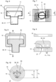
- FIGS 1 to 5 show a first embodiment of a channel system.
- the channel system comprises a C-channel type channel 10 having a longitudinal slot 11.
- the channel system further comprises a T-bolt 30 having a shaft 31 and a head 32.
- the T-bolt 30, in particular the head 32 thereof, is intended to be inserted through the longitudinal slot 11 into the channel 10, and to be locked within the channel 10 by rotation.
- the T-bolt 30 is shown in this engaged state.
- the channel 10 is preferably intended to be embedded in concrete.
- it can comprise at least one anchor rod 70, shown schematically and in figure 1 only.
- the channel 10 is provided with a channel serration 17 that extends alongside the longitudinal slot 11, wherein the channel serration 17 comprises a plurality of channel serration teeth 19.
- the T-bolt 30 is provided, namely on its head 32, with a corresponding bolt serration 37 comprising a plurality of bolt serration teeth 39.
- the bolt serration 37 is intended to interlock with the channel serration 17 when the T-bolt engages the channel 10 as shown in the drawings.
- both the channel serration 17 and the bolt serration 37 are isosceles trapezoidal.
- the channel serration 17 has a channel serration pitch p 17 , a channel serration heigh h 17 , and a channel serration included angle ⁇ 17 .
- the T-bolt 30 has a bolt serration pitch p 37 , a bolt serration heigh h 37 , and a bolt included angle ⁇ 37 .
- the bolt serration height h 37 is greater than the channel serration height h 17 (i.e. h 37 > h 17 ), and the bolt serration included angle ⁇ 37 is smaller than the channel serration included angle ⁇ 17 (i.e. ⁇ 37 ⁇ ⁇ 17 ).
- the bolt serration 37 reaches deeper into the channel serration 17 than does the channel serration 17 into the bolt serration 37, and, in particular, the bolt serration 37 reaches particularly deep into the channel serration 17.
- Figures 6 to 10 show an alternative embodiment of a channel system.
- the embodiment of figures 6 to 10 and the previous embodiment share a common basic concept. Therefore, in the following, focus will be on the differentiating features, whereas reference is made to the description above for the remaining features. Unless indicated otherwise, the description above applies mutatis mutandis to the embodiment of figures 6 to 10 .
- the embodiment of figures 6 to 10 differs from that of figures 1 to 5 in the cross-sectional shape of the respective serrations.
- the channel serration 17 and the bolt serration 37 both have isosceles trapezoidal cross-section, whereas in the embodiment of figures 6 to 10 the channel serration 17 and the bolt serration 37 both have sinusoidal cross-section.
- the bolt serration 37 thus has a bolt serration tip radius r 37
- the channel serration has a channel serration bottom radius r 17 . With respect to these radii, the following holds. r 17 > r 37 .
Landscapes
- Engineering & Computer Science (AREA)
- General Engineering & Computer Science (AREA)
- Architecture (AREA)
- Mechanical Engineering (AREA)
- Physics & Mathematics (AREA)
- Electromagnetism (AREA)
- Civil Engineering (AREA)
- Structural Engineering (AREA)
- Dowels (AREA)
- Connection Of Plates (AREA)
Abstract
Channel system comprising a channel and a T-bolt for engaging the channel through a longitudinal slot of the channel, wherein the channel has a channel serration comprising a plurality of channel serration teeth, wherein the channel serration has a channel serration pitch p17 and a channel serration height h17, and wherein the T-bolt has a bolt serration, for interlocking with the channel serration, wherein the bolt serration comprises a plurality of bolt serration teeth, wherein the bolt serration has a bolt serration pitch p37 and a bolt serration height h37, wherein the bolt serration pitch p37 and the channel serration p17 pitch are the same, characterized in that the bolt serration height h37 is greater than the channel serration height h17.
Description
- The invention relates to a channel system which comprises a channel and a T-bolt for engaging the channel through a longitudinal slot of the channel, according to the preamble of
claim 1. - Channel systems comprising an anchor channel intended to be cast into concrete and T-bolt type channel bolts intended for engaging the anchor channel are, for example, described in ICC-ES Evaluation Report ESR-3520, Revised May 2023. The products HBC-B and HBC-T described therein provide mechanical interlock between matching serrations of the channel bolt and the lips of the anchor channel. This interlock can provide particularly good shear resistance loads in the longitudinal direction.
- It is an object of the invention to provide a channel system that provides particularly good performance, whilst being particularly easy to manufacture.
- This object is achieved by a device according to
claim 1. Dependent claims refer to preferred embodiments of the invention. - Accordingly, there is provided a channel system comprising a channel and a T-bolt for engaging the channel through a longitudinal slot of the channel, wherein the channel has a channel serration comprising a plurality of channel serration teeth, wherein the channel serration has a channel serration pitch p17 and a channel serration height h17, and wherein the T-bolt has a bolt serration, for interlocking with the channel serration, wherein the bolt serration comprises a plurality of bolt serration teeth, wherein the bolt serration has a bolt serration pitch p37 and a bolt serration height h37, wherein the bolt serration pitch p37 and the channel serration p17 pitch are the same, characterized in that the bolt serration height h37 is greater than the channel serration height h17.
- The invention is based on the finding that in typical configurations, the strength (in particular the tensile strength or/and the compressive strength) of the channel tends to be lower than the strength of the T-bolt, leading to a potential shear failure mode in which the channel serration shears off initially. In view of this, the invention proposes to provide the bolt serration teeth with greater height as compared to the channel serration teeth which are engaged by the bolt serration teeth. As both serrations have same pitch, this can lead to particular deep engagement of the channel serration, so that the entire height of the (relatively low strength) channel serration is used for engagement. As a consequence, particularly good performance can be achieved at particularly low effort.
- The bolt serration pitch p37 and the channel serration p17 pitch are the same, i.e. p37 = p17. The bolt serration height h37 is greater than the channel serration height h17, i.e. h37 > h17.
- In particular, the channel can be intended to be embedded in concrete. Preferably, the channel can be an anchor channel. An anchor channel comprises at least one concrete anchor. In particular, the at least one concrete anchor can be an anchor rod attached to a bottom of the channel (wherein the bottom of the channel can in particular be that side of the channel that is opposite the longitudinal slot). The longitudinal slot provides access to the inside of the channel.
- The longitudinal slot of the channel is flanked by two channel lips. In particular, the channel serration is provided in one of the two channel lips. The channel can be provided with an additional channel serration, in particular in the respective other of the channel lips, and the T-bolt can have an additional bolt serration for interlocking with the additional channel serration.
- The plurality of channel serration teeth are in particular arranged parallel to one another. The channel serration pitch can be regarded as the distance between two adjacent channel serration teeth. The channel serration height can be considered to be the height measured from the bottom of the channel serration to the top of the channel serration. In particular, the channel serration height can be constant throughout the channel serration. The channel serration can also comprise at least one auxiliary channel tooth.
- In analogy, the plurality of bolt serration teeth are in particular arranged parallel to one another. The bolt serration pitch can be regarded as the distance between two adjacent bolt serration teeth. The bolt serration height can be considered to be the height measured from the bottom of the bolt serration to the top of the bolt serration. In particular, the bolt serration height can be constant throughout the bolt serration. The bolt serration can also comprise at least one auxiliary bolt tooth.
- The bolt serration is intended for interlocking with the channel serration. In this interlocked state, the bolt serration teeth reach into channel serration valleys formed between the channel serration teeth, and the channel serration teeth reach into bolt serration valleys formed between the bolt serration teeth. The bolt serration and the channel serration are in particular linear serrations. Additional teeth and/or additional serrations might be provided on the T-bolt or/and on the channel, e.g. in order to further improve functionality.
- It is particularly preferred that the following holds for the bolt serration height h37 and the channel serration height h17, respectively,


- Accordingly, the bolt serration height is at least 5%, 7% or 10% greater than the channel serration height. This can provide particularly good channel teeth engagement and loading, further increasing performance.
- It is particularly advantageous that the following holds for the bolt serration height h37 and the channel serration height h17,


- Accordingly, the bolt serration height is at least 0.2 millimeters (or 0.3 millimeters) greater than the channel serration height. For example, the bolt serration height h37 can be 1.8 mm ± 0.15 mm. The channel serration height h17 could e.g. be 1.5 mm + 0.3 mm/-0.1 mm.
- According to another preferred embodiment of the invention, the bolt serration has a bolt serration included angle α37, and the channel serration has a channel serration included angle α17, wherein the following holds:


- In accordance with usual definition, the included angles can be considered to be the angles included by the flanks of the respective serrations. According to the described embodiment, the included angle of the bolt serration is smaller than the included angle of the channel serration. In other words, the bolt serration teeth are sharper than the channel serration teeth.
- These embodiments can further improve serration engagement and loading of the channel serration. For example, a channel serration included angle α17 of 60° can be provided. The bolt serration included angle α37 could e.g. range from 55° to 60°, included, i.e.
55° ≤ α37 ≤ 60°. It is particularly preferred that:
- Advantageously, the bolt serration has a bolt serration tip radius r37, and the channel serration has a channel serration bottom radius r17, wherein the following holds:


- The bolt serration tip radius r37 is that radius that is formed at the tips of the bolt serration teeth, whereas the channel serration bottom radius r17 is that radius that is formed at the valleys formed between adjacent channel serration teeth. These embodiments can further improve serration engagement and loading of the channel serration. For example, the following can be provided:
- bolt serration tip radius r37 = 0.3 mm and/or
- channel serration bottom radius r17 = 0.6 mm.
- Advantageously, the channel and/or the T-bolt consist of steel. More preferably, the bolt serration consists of steel and the channel serration consists of steel. In both cases, the steel could also be coated. Steel can provide a particularly well performing channel system at particularly low effort.
- As already mentioned above, the bolt serration has preferably higher strength than the channel serration. It is particularly preferred that the material forming the bolt serration has higher tensile strength than the material forming the channel serration or/and that the material forming the bolt serration has higher compressive strength than the material forming the channel serration.
- The invention is explained in greater detail below with reference to preferred exemplary embodiments, which are depicted schematically in the accompanying drawings. Individual features of the exemplary embodiments presented below can be implemented either individually or in any combination within the scope of the present invention.
-
Figure 1 is side view of a first embodiment of a channel system. -
Figure 2 is a top view of the channel system offigure 1 . -
Figure 3 is a sectional view, according to A-A infigure 2 , of the channel system offigure 1 . -
Figure 4 is a sectional view, according to B-B infigure 3 , of the channel system offigure 1 . -
Figure 5 is a detail view Z, according tofigure 4 , of the channel system offigure 1 . -
Figure 6 is side view of a second embodiment of a channel system. -
Figure 7 is a top view of the channel system offigure 6 . -
Figure 8 is a sectional view, according to A-A infigure 7 , of the channel system offigure 6 . -
Figure 9 is a sectional view, according to B-B infigure 8 , of the channel system offigure 6 . -
Figure 10 is a detail view Z, according tofigure 9 , of the channel system offigure 6 . -
Figures 1 to 5 show a first embodiment of a channel system. The channel system comprises a C-channel type channel 10 having alongitudinal slot 11. The channel system further comprises a T-bolt 30 having a shaft 31 and ahead 32. The T-bolt 30, in particular thehead 32 thereof, is intended to be inserted through thelongitudinal slot 11 into thechannel 10, and to be locked within thechannel 10 by rotation. In the figures, the T-bolt 30 is shown in this engaged state. - The
channel 10 is preferably intended to be embedded in concrete. In particular, it can comprise at least oneanchor rod 70, shown schematically and infigure 1 only. - The
channel 10 is provided with achannel serration 17 that extends alongside thelongitudinal slot 11, wherein thechannel serration 17 comprises a plurality ofchannel serration teeth 19. The T-bolt 30 is provided, namely on itshead 32, with acorresponding bolt serration 37 comprising a plurality ofbolt serration teeth 39. Thebolt serration 37 is intended to interlock with thechannel serration 17 when the T-bolt engages thechannel 10 as shown in the drawings. In the embodiment offigures 1 to 5 , both thechannel serration 17 and thebolt serration 37 are isosceles trapezoidal. - The
channel serration 17 has a channel serration pitch p17, a channel serration heigh h17, and a channel serration included angle α17. In analogy, the T-bolt 30 has a bolt serration pitch p37, a bolt serration heigh h37, and a bolt included angle α37. - The channel serration pitch p17 and the bolt serration pitch p37 are generally the same, i.e. p17= p37. The bolt serration height h37 is greater than the channel serration height h17 (i.e. h37 > h17), and the bolt serration included angle α37 is smaller than the channel serration included angle α17 (i.e. α37 < α17). As a consequence, the
bolt serration 37 reaches deeper into thechannel serration 17 than does thechannel serration 17 into thebolt serration 37, and, in particular, thebolt serration 37 reaches particularly deep into thechannel serration 17. -
Figures 6 to 10 show an alternative embodiment of a channel system. The embodiment offigures 6 to 10 and the previous embodiment share a common basic concept. Therefore, in the following, focus will be on the differentiating features, whereas reference is made to the description above for the remaining features. Unless indicated otherwise, the description above applies mutatis mutandis to the embodiment offigures 6 to 10 . - In particular, the embodiment of
figures 6 to 10 differs from that offigures 1 to 5 in the cross-sectional shape of the respective serrations. In the embodiment offigures 1 to 5 , thechannel serration 17 and thebolt serration 37 both have isosceles trapezoidal cross-section, whereas in the embodiment offigures 6 to 10 thechannel serration 17 and thebolt serration 37 both have sinusoidal cross-section. In the embodiment offigures 6 to 10 , thebolt serration 37 thus has a bolt serration tip radius r37, and the channel serration has a channel serration bottom radius r17. With respect to these radii, the following holds.
- Again, the channel serration pitch p17 and the bolt serration pitch p37 are generally the same, i.e. p17 = p37, whereas the bolt serration height h37 is greater than the channel serration height h17 (i.e. h37 > h17), and the bolt serration included angle α37 is smaller than the channel serration included angle α17 (i.e. α37 < α17). As a consequence, the
bolt serration 37 again reaches deeper into thechannel serration 17 than does thechannel serration 17 into thebolt serration 37.
Claims (7)
- Channel system comprising a channel (10) and a T-bolt (30) for engaging the channel (10) through a longitudinal slot (11) of the channel (10),- wherein the channel (10) has a channel serration (17) comprising a plurality of channel serration teeth (19), wherein the channel serration (17) has a channel serration pitch p17 and a channel serration height h17, and- wherein the T-bolt (30) has a bolt serration (37), for interlocking with the channel serration (17), wherein the bolt serration (37) comprises a plurality of bolt serration teeth (39), wherein the bolt serration (37) has a bolt serration pitch p37 and a bolt serration height h37,- wherein the bolt serration pitch p37 and the channel serration p17 pitch are the same, characterized in that- the bolt serration height h37 is greater than the channel serration height h17.
- Channel system according to claim 1,
characterized in that
the following holds for the bolt serration height h37 and the channel serration height h17,


- Channel system according to any of the preceding claims,
characterized in that
the following holds for the bolt serration height h37 and the channel serration height h17,

- Channel system according to any of the preceding claims,
characterized in that
the bolt serration (37) has a bolt serration included angle α37 ≥ α17, and the channel serration (17) has a channel serration included angle α17, wherein the following holds:
- Channel system according to any of the preceding claims,
characterized in that
the bolt serration (37) has a bolt serration tip radius r37, and the channel serration (17) has a channel serration bottom radius r17, wherein the following holds:
- Channel system according to any of the preceding claims,
characterized in that
the bolt serration (37) consists of steel and the channel serration (17) consists of steel. - Channel system according to any of the preceding claims,
characterized in thatthe material forming the bolt serration (37) has higher tensile strength than the material forming the channel serration (17) or/andthe material forming the bolt serration (37) has higher compressive strength than the material forming the channel serration (17).
Priority Applications (3)
| Application Number | Priority Date | Filing Date | Title |
|---|---|---|---|
| EP23197675.4A EP4524339A1 (en) | 2023-09-15 | 2023-09-15 | Channel system |
| CN202480051123.XA CN121712953A (en) | 2023-09-15 | 2024-08-27 | Trench system |
| PCT/EP2024/073902 WO2025056314A1 (en) | 2023-09-15 | 2024-08-27 | Channel system |
Applications Claiming Priority (1)
| Application Number | Priority Date | Filing Date | Title |
|---|---|---|---|
| EP23197675.4A EP4524339A1 (en) | 2023-09-15 | 2023-09-15 | Channel system |
Publications (1)
| Publication Number | Publication Date |
|---|---|
| EP4524339A1 true EP4524339A1 (en) | 2025-03-19 |
Family
ID=88093688
Family Applications (1)
| Application Number | Title | Priority Date | Filing Date |
|---|---|---|---|
| EP23197675.4A Withdrawn EP4524339A1 (en) | 2023-09-15 | 2023-09-15 | Channel system |
Country Status (3)
| Country | Link |
|---|---|
| EP (1) | EP4524339A1 (en) |
| CN (1) | CN121712953A (en) |
| WO (1) | WO2025056314A1 (en) |
Citations (2)
| Publication number | Priority date | Publication date | Assignee | Title |
|---|---|---|---|---|
| GB2050549A (en) * | 1979-05-25 | 1981-01-07 | Bicc Ltd | Anchoring nuts or screws |
| EP1323936A2 (en) * | 2001-12-05 | 2003-07-02 | HILTI Aktiengesellschaft | Oblong profile |
-
2023
- 2023-09-15 EP EP23197675.4A patent/EP4524339A1/en not_active Withdrawn
-
2024
- 2024-08-27 CN CN202480051123.XA patent/CN121712953A/en active Pending
- 2024-08-27 WO PCT/EP2024/073902 patent/WO2025056314A1/en active Pending
Patent Citations (2)
| Publication number | Priority date | Publication date | Assignee | Title |
|---|---|---|---|---|
| GB2050549A (en) * | 1979-05-25 | 1981-01-07 | Bicc Ltd | Anchoring nuts or screws |
| EP1323936A2 (en) * | 2001-12-05 | 2003-07-02 | HILTI Aktiengesellschaft | Oblong profile |
Non-Patent Citations (1)
| Title |
|---|
| ICC-ES EVALUATION REPORT ESR-3520, May 2023 (2023-05-01) |
Also Published As
| Publication number | Publication date |
|---|---|
| WO2025056314A1 (en) | 2025-03-20 |
| CN121712953A (en) | 2026-03-20 |
Similar Documents
| Publication | Publication Date | Title |
|---|---|---|
| KR101543480B1 (en) | Thread forming fastener | |
| EP2331832B1 (en) | Bearing cap | |
| EP1706346B1 (en) | Lift system | |
| EP3081706B1 (en) | Anchor rail for anchoring in concrete | |
| CA2999618C (en) | Thread-forming screw with separate thread spiral and different part flank angles | |
| EP2016298B1 (en) | Pierce nut and use thereof | |
| US20140112725A1 (en) | Universal connecting element for sheet pile wall components | |
| EP1944107B1 (en) | Drill head for drill and drill | |
| US12092143B2 (en) | Retainer and a retainer and nut assembly | |
| DE102008037538A1 (en) | Traction system for an elevator installation | |
| US7947380B2 (en) | Sheet material | |
| US20050001428A1 (en) | Anchor ring | |
| EP1946891A1 (en) | Clamp head | |
| CA2540492A1 (en) | Shear connector using perforated and/or cut out plate | |
| WO2025056314A1 (en) | Channel system | |
| WO2007031128A1 (en) | Connecting device | |
| EP2478163A1 (en) | Moldable anchor rail | |
| EP2395248A2 (en) | Connecting arrangement and method of fastening a bolt | |
| DE102008037537A1 (en) | Traction drive and elevator system with this traction drive | |
| KR101692649B1 (en) | Pre-stressing tendon separation device | |
| EP2703331B1 (en) | Traction system using a multi-tendon cable with a deflection angle | |
| EP3443164B1 (en) | Profiled bearing and rail system | |
| EP3561195B1 (en) | Ribbed reinforcing bar | |
| JPWO2018030361A1 (en) | Longitudinal structure of steel members | |
| DE102007020051A1 (en) | Hard metal plate for rock drills and rock drills |
Legal Events
| Date | Code | Title | Description |
|---|---|---|---|
| PUAI | Public reference made under article 153(3) epc to a published international application that has entered the european phase |
Free format text: ORIGINAL CODE: 0009012 |
|
| STAA | Information on the status of an ep patent application or granted ep patent |
Free format text: STATUS: THE APPLICATION HAS BEEN PUBLISHED |
|
| AK | Designated contracting states |
Kind code of ref document: A1 Designated state(s): AL AT BE BG CH CY CZ DE DK EE ES FI FR GB GR HR HU IE IS IT LI LT LU LV MC ME MK MT NL NO PL PT RO RS SE SI SK SM TR |
|
| STAA | Information on the status of an ep patent application or granted ep patent |
Free format text: STATUS: THE APPLICATION IS DEEMED TO BE WITHDRAWN |
|
| 18D | Application deemed to be withdrawn |
Effective date: 20250920 |