EP4524335A1 - Toilet tank and channel disinfection - Google Patents
Toilet tank and channel disinfection Download PDFInfo
- Publication number
- EP4524335A1 EP4524335A1 EP24188384.2A EP24188384A EP4524335A1 EP 4524335 A1 EP4524335 A1 EP 4524335A1 EP 24188384 A EP24188384 A EP 24188384A EP 4524335 A1 EP4524335 A1 EP 4524335A1
- Authority
- EP
- European Patent Office
- Prior art keywords
- disinfection
- tank
- toilet
- toilet tank
- water
- Prior art date
- Legal status (The legal status is an assumption and is not a legal conclusion. Google has not performed a legal analysis and makes no representation as to the accuracy of the status listed.)
- Pending
Links
Images








Classifications
-
- E—FIXED CONSTRUCTIONS
- E03—WATER SUPPLY; SEWERAGE
- E03D—WATER-CLOSETS OR URINALS WITH FLUSHING DEVICES; FLUSHING VALVES THEREFOR
- E03D1/00—Water flushing devices with cisterns ; Setting up a range of flushing devices or water-closets; Combinations of several flushing devices
- E03D1/02—High-level flushing systems
- E03D1/18—Cisterns empty when not in action, e.g. with pressure tanks, with swivel-mounted cisterns
-
- E—FIXED CONSTRUCTIONS
- E03—WATER SUPPLY; SEWERAGE
- E03D—WATER-CLOSETS OR URINALS WITH FLUSHING DEVICES; FLUSHING VALVES THEREFOR
- E03D9/00—Sanitary or other accessories for lavatories ; Devices for cleaning or disinfecting the toilet room or the toilet bowl; Devices for eliminating smells
- E03D9/02—Devices adding a disinfecting, deodorising, or cleaning agent to the water while flushing
- E03D9/03—Devices adding a disinfecting, deodorising, or cleaning agent to the water while flushing consisting of a separate container with an outlet through which the agent is introduced into the flushing water, e.g. by suction ; Devices for agents in direct contact with flushing water
- E03D9/033—Devices placed inside or dispensing into the cistern
- E03D9/037—Active dispensers, i.e. comprising a moving dosing element
-
- E—FIXED CONSTRUCTIONS
- E03—WATER SUPPLY; SEWERAGE
- E03D—WATER-CLOSETS OR URINALS WITH FLUSHING DEVICES; FLUSHING VALVES THEREFOR
- E03D9/00—Sanitary or other accessories for lavatories ; Devices for cleaning or disinfecting the toilet room or the toilet bowl; Devices for eliminating smells
-
- E—FIXED CONSTRUCTIONS
- E03—WATER SUPPLY; SEWERAGE
- E03D—WATER-CLOSETS OR URINALS WITH FLUSHING DEVICES; FLUSHING VALVES THEREFOR
- E03D9/00—Sanitary or other accessories for lavatories ; Devices for cleaning or disinfecting the toilet room or the toilet bowl; Devices for eliminating smells
- E03D9/002—Automatic cleaning devices
-
- E—FIXED CONSTRUCTIONS
- E03—WATER SUPPLY; SEWERAGE
- E03D—WATER-CLOSETS OR URINALS WITH FLUSHING DEVICES; FLUSHING VALVES THEREFOR
- E03D9/00—Sanitary or other accessories for lavatories ; Devices for cleaning or disinfecting the toilet room or the toilet bowl; Devices for eliminating smells
- E03D9/005—Devices adding disinfecting or deodorising agents to the bowl
Definitions
- the present application relates generally to the disinfection of a toilet tank and water channels fluidly connected to the toilet tank.
- the following embodiments include apparatus and techniques for disinfection of the interior of a toilet tank and/or channels extending away from the toilet tank. At least one channel may extend to the rim of the toilet bowl. At least one channel may extend to the sump of the toilet bowl. Some of the following examples include techniques that are specifically applicable to an empty toilet tank. In some examples, devices and processes are included for the purpose of substantially completely emptying the tank so that water is removed. Some of the following examples include techniques that are applicable to a toilet tank at least partially full of water or full to a predetermined flush volume.
- the following embodiments include devices and techniques for the reduction, mitigation, or prevention of biofilms in plumbing devices and/or disinfection of plumbing devices.
- the plumbing devices may include pipes, faucets, bathtubs, showers, water softeners, water heaters, toilets or other devices.
- the term "plumbing fixture” refers to an apparatus that is connected to a plumbing system of a house, building or another structure.
- the term “bathroom fixture” may more specifically refer to individual types of plumbing fixtures found in the bathroom.
- kitchen fixture may more specifically refer to individual types of plumbing fixtures found in the kitchen.
- FIG. 1 illustrates an example toilet (plumbing device) for use with a disinfection system.
- a toilet 1100 with the disinfection system is illustrated according to an exemplary embodiment of the present disclosure.
- the toilet 1100 may include a tank (e.g., container, reservoir, etc.), shown as a tank 101, and a pedestal (e.g., base, stand, support, etc.), shown as a pedestal 1104.
- the tank 101 may be coupled to, and supported by, the pedestal 1104, which may be positioned on a floor.
- the tank 101 and the pedestal 1104 may be formed together as a single component.
- the tank 101 may be mounted nearby on a wall, or within a wall.
- the tank 101 is configured to receive water (e.g., via a fill valve of the toilet 1100, etc.) and store the water in between flushes.
- the pedestal 1104 includes a bowl 1105 and may be configured to receive the water from the tank 101 to flush contents of bowl into a sewage line.
- the pedestal 1104 may be mounted on the wall of a lavatory and the bowl may be configured to receive water from a fluid supply source such as a household water supply.
- the bowl 1105 of the pedestal 1104 includes a sump (e.g. a receptacle) and an outlet opening, wherein water and waste is collected in the sump until being removed through the outlet opening, such as when the contents of the bowl are flushed into a sewage line, septic system, or other sanitary system.
- the toilet 1100 further includes a trapway, and the trapway may be fluidly connected to the bowl via the sump. The trapway fluidly connects the sump to the outlet opening.
- FIGS. 2A, 2B , 3 , and 4 illustrate example systems for removing or emptying substantially all of the water from the toilet tank 101. While water is typically emptied from the toilet tank 101 in the process of flushing (e.g., during the flush cycle), not all of the water is removed. The remaining water may allow biofilms or other waterborne microorganisms to survive continuously in the tank. If all, or substantially all, of the water is emptied from the tank 101, the waterborne bacteria or biofilm is removed with it. In addition, removing the water completely from the tank 101 allows a disinfection system to treat the entirety of the interior of the tank 101.
- a biofilm is a group of one or more types of microorganisms that can grow on a variety surfaces.
- Example microorganisms that form biofilms include bacteria, fungi and protists.
- Biofilms may form on bodies of water, plant tissue, animal tissue, teeth, underwater, and inside of other living organisms. Potentially, biofilms may form, generally, on any water exposed areas. Plumbing fixtures, fittings and water supply systems and installations for washing, showering, bathing and similar devices may include water exposed areas.
- FIG. 2B also eliminates the collection of water between the flush valve 121 and the bottom surface of the tank 101 by placing the opening of the flush valve 121 flush with the bottom surface of the tank 101 or below the bottom surface of the tank 101.
- the bottom surface of the tank 101 in FIG. 2B includes slanted portions 131 of the bottom of the tank 101.
- the slanted portions 131 are angled at predetermined angle ( ⁇ ) with respect to a horizontal (dotted line in FIG. 2B ).
- the horizontal line is substantially parallel with the earth's surface and/or perpendicular to the direction of gravity.
- the slanted portions 131 allow the water in the bottom of the tank 101 to flow toward the opening of the flush valve 121 so that the tank 101 is completely emptied.
- the empty tank discourages the growth of biofilms or other microorganisms and also provides opportunity for the disinfection of the interior surfaces within the tank 101.
- FIG. 3 illustrates a cavity 132 at the bottom of the tank 101.
- the cavity 132 may include a float F that detect whether there is any water left in the tank 101.
- the float may be positioned a predetermined vertical distance (e.g., 1-10 millimeters) above the valve plate V or opening in the tank 101.
- the float F may be replaced with another type of sensor (e.g., water sensor).
- the float F may be mechanically coupled to the valve plate V of the flush valve 121 so that when the float F is suspended by any quantity of water in the tank 101, the valve plate V is held open so that water can flow from the tank 101.
- the vale plate V may be allowed to close.
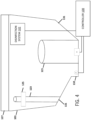
- FIG. 4 illustrates another example in which the flush valve 121 is electronically controlled.
- the float F or other sensor provides sensor data to the controller 100 indicative of a water level in the tank 101.
- the controller 100 provides commands to the flush plate V or an actuator coupled to the flush plate V.
- the actuator may include a motor or a solenoid.
- the controller 100 determined whether the water is below a predetermined threshold (e.g., the threshold may be the smallest measurable water level).
- the controller 100 may maintain the flush plate V of the flush valve 121 in an open state until the predetermined threshold has been reached. When the predetermined threshold has been reached the controller 100 may close the flush plate V.
- the flush plate V may be replaced with a pump.
- the controller 100 instructs the pump to pump water from the tank 101 when the until the predetermined threshold has been reached. When the predetermined threshold has been reached the controller 100 may turn off the pump.
- the controller 100 may also communicate with a disinfection system 102.
- the disinfection system 102 may be implemented according to any of the following embodiments.
- the controller 100 may send instructions or commands to the disinfection system 102. For example, when the controller 100 has determined the water has been emptied completely from the tank 101, the controller 100 may instruct the disinfection system 102 to disinfect the interior of the tank 101.
- the disinfection dispenser 102 is configured to dispense a disinfection material into the toilet tank 101 and the at least one disinfection channel extending from the drain opening of the toilet tank to the pedestal for the toilet.
- the disinfection system 102 may be implemented in toilet bowls, trapways for toilets, trapways for lavatories, whirlpool harnesses, garbage disposals, sinks, fruits/vegetable washers, scents dispensers, humidifiers, or other devices.
- Each of the examples herein may be mounted in or otherwise coupled to or associated with a toilet tank 101 having a glazed interior surface. Glazing the interior of the tank reduces the surface roughness for the adhesion of biofilms or other microorganisms.
- the interior of the tank 101 may be coated with an antimicrobial or highly hydrophobic coatings.
- antimicrobials silver
- FIG. 5 illustrates an example light disinfection device 141 (an example disinfection system 102), a toilet tank 101, a drain opening 135 at a bottom of the toilet tank 101, at least one disinfection channel extending from the drain opening of the toilet tank to a pedestal for the toilet, and a flush valve 121 configured to empty the toilet tank through the drain opening to below a predetermined level. Additional, different, or fewer components may be included.
- the light disinfection device 141 includes one or more light sources that emit a predetermined wavelength or frequency of light into the interior of the tank 101.
- the one or more light sources may be arranged to that substantially all of the interior walls of the toilet tank 101 are irradiated.
- the one or more light sources may be arranged so that the cannister of the flush valve 121 does not cast a shadow between the light source and the interior wall.
- one or more light sources may be positioned on opposite sides of the flush valve 121, as shown in FIG. 5 .
- one or more light sources may be mounted on the inside of the lid of the toilet tank 101 and direct light downward into the toilet tank 101.
- the one or more light sources may emit a variety of types of irradiation such as an ultraviolet (UV) light.
- the UV light may have a predetermined frequency or wavelength, which may be a range of wavelengths or frequencies for the light.
- the predetermined frequency or wavelength may be configured to reduce or eliminate biofilm or other microorganisms.
- the controller 100 may send commands to the light to start the light or stop the light.
- the controller 100 may send commands to the light to set the wavelength of the light.
- the light may include ultra-violet germicidal irradiation (UVGI) to kill microbes in the water or on surfaces.
- UVGI ultra-violet germicidal irradiation
- the germicidal irradiation may be optimized by a wavelength band of 200 to 280 nanometers (nm), or a band centered around 405 nm.
- the lights may be light emitting diodes (LEDs).
- the lid may include a sensor or other switch to cause the one or more light sources to turn on or off.
- a sensor or other switch to cause the one or more light sources to turn on or off.
- an electrical contact on the tank 101 and the lid may effectively form a switch.
- the lid is removed the connection between the contacts is interrupted, causing the one or more light sources to turn off.
- a similar feedback system may be implemented with other types of sensors.
- FIG. 6 illustrates an example fogging disinfection device 143 configured to generate an emit a cloud 144 into the interior of the toilet 101.
- the cloud 144 may be generated when the tank 101 is empty.
- the controller 100 may receive sensor data indicative of an empty tank and activate the fogging device 143 in response to the sensor data.
- the cloud 144 may include peroxide H 2 O 2 (vapor). Additional, different, or fewer components may be included.
- the cloud 144 may include a disinfectant.
- the cloud 144 may fill the space inside of the tank 101, reaching each of the interior surfaces of the tank 101.
- the cloud 144 may move naturally or forcibly to fill the spaces in one or more channels in communication with the tank 101.
- the channels may include at least one channel extending to the rim of the toilet bowl and/or at least one channel extending to the sump of the toilet bowl.
- the cloud 144 may be emitted above the water level in a full or partially full tank.
- the flush cycle begins, and water is pulled by gravity into the channel to the toilet bowl, negative air pressure created by the water pulls the cloud 144 into the channels to the toilet bowl. In this way, the cloud 144 comes in contact with both the interior walls of the tank 101 and the interior walls of the channels extending to the bowl.
- FIG. 7 illustrates an example fogging disinfection device with increased air flow.
- a fan 145 may be mounted inside the tank 101.
- the fan 145 is configured to increase the mass flow of the aerosols generated by the fogging device 143 to the interior of the tank 101, through the channels to the bowl, and into the bowl.
- the fan 145 may be controlled by controller 100.
- the controller 100 may send instructions or commands to the fan 145 to operate during the flush cycle. For example, when the controller 100 has instructed the flush valve 121 to open, the controller 100 may operate the fan 145 to help the cloud 144 expand. In another example, when the sensor data indicates that water has been emptied completely from the tank 101, the controller 100 may instruct the fan 145 to operate. In some examples, the controller 100 may activate the fan 145 at a predetermined delay after activation of the fogging device 143 (or other disinfection system).
- FIG. 8 illustrates an example ultrasonic disinfection device 147 mounted in the toilet tank 101.
- the ultrasonic disinfection device 147 may include a transducer configured to emit ultrasonic waves into the tank 101.
- the ultrasonic waves are mechanical vibrations that strike the interior surfaces of the tank 101 and vibrate or otherwise shake loose particles such as biofilm and other microorganisms.
- the ultrasonic waves from the ultrasonic disinfection device 147 may cause bubbles within the water to implode and collapse (e.g., cavitation) on the surfaces of the tank 101.
- the implosion may create a scrubbing action that dislodges particles such as biofilm and other microorganisms from the surfaces of the tank 101.
- the ultrasonic disinfection device 147 may be operated underwater or in a substantially empty tank.
- the controller 100 may send instructions or commands to the ultrasonic disinfection device 147 to operate during the flush cycle. For example, when the controller 100 has instructed the flush valve 121 to open, the controller 100 may operate the ultrasonic disinfection device 147. In another example, when the sensor data indicates that water has been emptied completely from the tank 101, the controller 100 may instruct the ultrasonic disinfection device 147 to operate. The controller 100 may instruct the ultrasonic disinfection device 147 to operate regardless of whether the tank substantially includes water or is substantially empty.
- FIG. 9 illustrates an example flow chart for disinfection of a substantially empty tank. Additional, different, or fewer acts may be included.
- the controller 100 receives an indication of an empty toilet tank.
- the indication of the empty toilet tank may include sensor data, timing data, or a flush cycle trigger.
- the sensor data may be received from a water sensor or a float in the tank.
- the timing data may be received from a timer (e.g., integrated with the controller) that indicates a predetermined timing from an event such as the start of the flush cycle.
- the flush cycle trigger may be a user input (e.g., lever actuation, button push, or remote control signal) or a command to open the flush valve 121.
- the controller generates a disinfection command for a disinfection system 102 in the empty toilet tank.
- the disinfection command may start the operation of any of the devices described herein including a fogger, a chemical dispenser, an ozone generator, an electrolyzer, or an ultrasonic emitter.
- a material is provided from the disinfection system 102 to an interior surface of the empty toilet tank 101 or a disinfection channel fluidly coupled to the empty toilet tank.
- the disinfection channel may extend from the tank to one or more rim holes in the toilet bowl.
- the disinfection channel may extend from the tank to one or more sump jets in the toilet bowl.
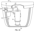
- FIG. 10 illustrates an example chemical distribution device 151.
- One or more compounds may be mixed with the chemical distribution device 151 with water from the fill valve 123 then dispensed directly into the tank and/or into the flush valve 121 through one or more channels connected to the bowl.
- the chemical distribution device 151 may dispense hydrogen peroxide (H 2 O 2 ), chlorines and peracedic acid (PAA), polyphosphates (e.g., sodium hexametaphosphate (SHMP), tetrapotassium pyrophosphate (TKPP), etc.), low pH acids (e.g., hydrogen chloride (HCL), dihydrogen phosphate (H2PO4), trisodium phosphate (TSP), ethylenediaminctetraacidic acid (EDTA), and compounds thereof, citric acid, acetic acid, as well as other acids and/or sequestering agents.
- HCL hydrogen chloride
- H2PO4 dihydrogen phosphate
- TSP trisodium phosphate
- EDTA ethylenediaminctetraacidic acid
- DDAC didecyldimethyl ammonium chloride
- NaOCI sodium hypochlorite
- PAA formic acid
- TSP formic acid
- other disinfectants e.g., quaternary disinfectants
- biocides include (but are not limited to) didecyldimethyl ammonium chloride (DDAC), sodium hypochlorite (NaOCI) such as bleach, PAA, triclosan, formic acid, TSP, and compounds thereof, as well as other disinfectants (e.g., quaternary disinfectants) and biocides.
- DDAC didecyldimethyl ammonium chloride
- NaOCI sodium hypochlorite
- PAA formic acid
- TSP formic acid
- biocides formic acid
- other disinfectants e.g., quaternary disinfectants
- biocides e.g., quaternary disinfectants
- FIG. 11 illustrates an example electrolyzed water distribution device 153.
- the electrolyzed water distribution device 153 is configured to electrolyze the tank water to generate hypochlorous acid using an electric charge and the residual salt in the water.
- the electrolysis process may produce HOCI, O 3 , and/or H 2 O 2 .
- additional salt i.e., salt not residual in the water
- Other byproducts such as hydrogen gas may be vented from the tank 101.
- the electrolyzed water distribution device 153 may comprise two plates (e.g., a cathode plate and an anode plate). Each plate may be formed of metal or a conductive material. Each plate may be electrically connected to a power source directly or through controller 100.
- the anode may be disposable. That is, the user may remove and reinstall the anode at a time interval or as needed. Vinegar or peracedic acid may be added to the water as a reactant.
- the controller 100 may send commands to the electrolyzed water distribution device 153.
- the controller 100 may provide current (e.g., increase current) to the electrolyzed water distribution device 153 in order to increase the concentration of hypochlorous acid in the water.
- the controller 100 may decrease current to the electrolyzed water distribution device 153 in order to decrease the concentration of hypochlorous acid in the water.
- a feedback sensor may detect the pH level in the water (e.g., acidic property or basic property). For example, a predetermined pH (e.g., 5.5 or 6.0) may indicate strong cleaning ability of the solution. A neutral pH (e.g., 7.0) may indicate an equal concentration of hypochlorous acid and hypochlorite ion.
- the controller 100 may compare the pH to a threshold level. When the detected pH is greater than the threshold the current is increased to increase the amount of hypochlorous acid. When the detected pH is less than the threshold the current is decreased to decrease the amount of hypochlorous acid.
- FIG. 12 illustrates an example ozone distribution device 155.
- the ozone may be formed by an ozone generator using a variety of techniques, including corona discharge, ultraviolet light, cold plasma, and other techniques.
- a corona charger may be configured to accumulate electric charge from the power source and apply the electric charge to air from the air source.
- a corona discharge a corona discharge tube or an ozone plate is used.
- an electrolytic ozone produces ozone by splitting water molecules.
- Such an ozone generator 110 includes a water electrolysis device that splits water molecules into H 2 , O 2 , and O 3 .
- the hydrogen gas, H 2 may be removed to leave oxygen and ozone as the only products of the reaction.
- Electrolytic ozone generation may produce at higher concentrations (20-30%) than the corona discharge technique.
- the electrolytic techniques may also avoid nitrogen gases.
- the controller 100 may send commands to the ozone generator.
- the commands may initiate the generation of ozone.
- the commands may be triggered by a time schedule (e.g., once every predetermined time period or at certain times of day).
- the commands may be triggered by a flush cycle. That is, the controller 100 may send a command to the ozone generator 110 to generate ozone when the tank is filled.
- the controller 100 may send a command to the ozone generator to generate ozone in response to a user input.
- a flush cycle may be initiated by operation of an actuator.
- the actuator may be a button configured to initiate the flush cycle when depressed (or pulled) a predetermined distance or when touched, a lever configured to activate when rotated a predetermined angular travel, or any suitable device configured to activate based on an input manipulation by a user.
- the actuator may be a sensor (e.g., a proximity sensor) and the flush cycle may be automatically initiated (e.g., by a controller) based on sensor data received from the sensor.
- the ozone generator of FIG. 12 may convert the oxygen in the water into ozone.
- the ozone distribution device 155 may be submerged in water and include a pump driven by the controller 100. The pump propels water through the ozone distribution device 155.
- the ozone distribution device 155 may include an ozone generation cell configured to convert the O 2 in the water into ozone O 3 . In the interim, hydroxyl radicals may be formed which react to form ozone.
- the ozone will be present in the water for a time period (e.g., 20 to 30 minutes) reducing pollutants in the water.
- the ozone generation cell may be implemented with electrodes separated by a membrane.
- the ozone generation cell may be on a circuit board or microchip. The water may flow through openings in the circuit board or microchip.
- the ozone distribution device 155 included the ozone distribution cell implemented on a circuit board or microchip may be incorporated in another flow of water in the toilet.
- the fill valve 123 may include the ozone distribution cell.
- ozone is created by the ozone distribution cell.
- the ozone distribution device 155 may be included in other channels or passages such as a rim passage or the flush valve 121.
- the ozone generator 155 and the ozone distribution cell may not be operated by the controller 100 and the pump. Instead, the flow of water is provided by the water supply and the operation of the ozone generator 155 is initiated in response to the flow of water.
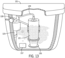
- FIG. 13 illustrates an example bacteria distribution device 157.
- the bacteria distribution device 157 may be loaded by a user with live beneficial bacteria.
- the bacteria may be dispensed into the tank water from the bacteria distribution device 157.
- This beneficial bacteria create a positive environment where it eats or otherwise destroys harmful bacteria.
- beneficial bacteria compete with the harmful bacteria for food and resources, consequently preventing the growth of harmful bacteria.
- a residual amount of bacteria would remain in the tank 101 after every flush.
- FIG. 14 illustrates an example light 161 and catalyst 163 device.
- the catalyst 163 may include an object having a passage through which water can travel.
- the catalyst 163 may have a tubular shape as shown in FIG. 14 .
- Other shapes may include a plate or a disc.
- the catalyst 163 may have a coating or be otherwise treating with a substance (e.g., catalyst material) that is activated by the light 161.
- the activated catalyst material with the water generated hydroxyl radicals which disinfect the water.
- the catalyst material may include titanium oxide (TiO 2 ).
- the light 161 may emit ultraviolet light having a predetermined wavelength.
- the light 161 may be a UV-C lamp that produces light with a 254 nanometer wavelength.
- the UV-C lamp may produce light in a range such as 240-315 nanometer wavelength.
- other wavelengths of ultraviolet light e.g., 185 nanometer wavelength
- the light 161 may also be coated with a catalyst material.
- the light 161 may include one or more LEDs.
- the LEDs may be powered by a DC power source, a battery, or a power generator.
- the power generator may be operated based on the water supply at the fill valve 123 to turn a turbine that rotates a generator to generate electricity.
- Example ultraviolet photo catalysts included titanium dioxide (TiO 2 ), zinc oxide (ZnO), tin oxide (SnO2), tungsten oxide (WO 3 ), cadmium sulfide (CdS), ZnS, CdSe, WS 2 , MoS 2 , and others.
- the catalyst may include at least one phosphate bead.
- heat from the light 161 may cause natural convection in the water of the tank. Water that is heated near the light 161 is caused to travel upward. Other cooler water takes its place near the light 161. This process repeats to circulate water within the tank 101.
- Another circulation device may include a powered device that circulates water within the tank 101.
- the powered device may be a motor.
- Examples for the circulation device may include an impellor, an agitator, or a pump.
- the light 161 and catalyst 163 device may be used in any type of water container.
- Example devices with applicable water containers include whirlpool harnesses, garbage disposals, self-cleaning water filters, waste water heat recovery systems, holding/settling/storage tanks for greywater or rainwater systems, commercial hand sanitizer, shower systems, recirculating showers, aerosol disinfection systems (e.g., in a lamp.
- FIG. 15 illustrates an example controller for any of the disinfection systems.
- the controller 400 may include a processor 300, a memory 352, and a communication interface 353 for interfacing with devices or to the internet and/or other networks 346.
- a sensor interface may be configured to receive data from the sensors described herein or data from any source for detecting the presence of water, detecting the presence of or strength of disinfectant, detecting the actuation of a flush cycle, detecting the presence of a user or gesture, of the devices described herein.
- the components of the control system 400 may communicate using bus 348.
- the control system 400 may be connected to a workstation or another external device (e.g., control panel) and/or a database for receiving user inputs, system characteristics, and any of the values described herein.
- control system 400 may include a drive unit 340 for receiving and reading non-transitory computer media 341 having instructions 342. Additional, different, or fewer components may be included.
- the processor 300 is configured to perform instructions 342 stored in memory 352 for executing the algorithms described herein.
- a display 350 may be supported by any of the components described herein. The display 350 may be combined with the user input device 355.
- Processor 300 may be a general purpose or specific purpose processor, an application specific integrated circuit (ASIC), one or more programmable logic controllers (PLCs), one or more field programmable gate arrays (FPGAs), a group of processing components, or other suitable processing components.
- Processor 300 is configured to execute computer code or instructions stored in memory 352 or received from other computer readable media (e.g., embedded flash memory, local hard disk storage, local ROM, network storage, a remote server, etc.).
- the processor 300 may be a single device or combinations of devices, such as associated with a network, distributed processing, or cloud computing.
- Memory 352 may include one or more devices (e.g., memory units, memory devices, storage devices, etc.) for storing data and/or computer code for completing and/or facilitating the various processes described in the present disclosure.
- Memory 352 may include random access memory (RAM), read-only memory (ROM), hard drive storage, temporary storage, non-volatile memory, flash memory, optical memory, or any other suitable memory for storing software objects and/or computer instructions.
- RAM random access memory
- ROM read-only memory
- ROM read-only memory
- Memory 352 may include database components, object code components, script components, or any other type of information structure for supporting the various activities and information structures described in the present disclosure.
- Memory 352 may be communicably connected to processor 300 via a processing circuit and may include computer code for executing (e.g., by processor 300) one or more processes described herein.
- memory 298 may include graphics, web pages, HTML files, XML files, script code, shower configuration files, or other resources for use in generating graphical user interfaces for display and/or for use in interpreting user interface inputs to make command, control, or communication decisions.
- the communication interface 353 may include any operable connection.
- An operable connection may be one in which signals, physical communications, and/or logical communications may be sent and/or received.
- An operable connection may include a physical interface, an electrical interface, and/or a data interface.
- the communication interface 353 may be connected to a network.
- the network may include wired networks (e.g., Ethernet), wireless networks, or combinations thereof.
- the wireless network may be a cellular telephone network, an 802.11, 802.16, 802.20, or WiMax network, a Bluetooth pairing of devices, or a Bluetooth mesh network.
- the network may be a public network, such as the Internet, a private network, such as an intranet, or combinations thereof, and may utilize a variety of networking protocols now available or later developed including, but not limited to TCP/IP based networking protocols.
- While the computer-readable medium (e.g., memory 352) is shown to be a single medium, the term “computer-readable medium” includes a single medium or multiple media, such as a centralized or distributed database, and/or associated caches and servers that store one or more sets of instructions.
- the term “computer-readable medium” shall also include any medium that is capable of storing, encoding, or carrying a set of instructions for execution by a processor or that cause a computer system to perform any one or more of the methods or operations disclosed herein.
- the computer-readable medium can include a solid-state memory such as a memory card or other package that houses one or more non-volatile read-only memories. Further, the computer-readable medium can be a random access memory or other volatile re-writable memory. Additionally, the computer-readable medium can include a magneto-optical or optical medium, such as a disk or tapes or other storage device to capture carrier wave signals such as a signal communicated over a transmission medium. A digital file attachment to an e-mail or other self-contained information archive or set of archives may be considered a distribution medium that is a tangible storage medium.
- the disclosure is considered to include any one or more of a computer-readable medium or a distribution medium and other equivalents and successor media, in which data or instructions may be stored.
- the computer-readable medium may be non-transitory, which includes all tangible computer-readable media.
- dedicated hardware implementations such as application specific integrated circuits, programmable logic arrays and other hardware devices, can be constructed to implement one or more of the methods described herein.
- Applications that may include the apparatus and systems of various embodiments can broadly include a variety of electronic and computer systems.
- One or more embodiments described herein may implement functions using two or more specific interconnected hardware modules or devices with related control and data signals that can be communicated between and through the modules, or as portions of an application-specific integrated circuit. Accordingly, the present system encompasses software, firmware, and hardware implementations.
- inventions of the disclosure may be referred to herein, individually and/or collectively, by the term "invention" merely for convenience and without intending to voluntarily limit the scope of this application to any particular invention or inventive concept.
- inventions may be referred to herein, individually and/or collectively, by the term "invention" merely for convenience and without intending to voluntarily limit the scope of this application to any particular invention or inventive concept.
- specific embodiments have been illustrated and described herein, it should be appreciated that any subsequent arrangement designed to achieve the same or similar purpose may be substituted for the specific embodiments shown.
- This disclosure is intended to cover any and all subsequent adaptations or variations of various embodiments. Combinations of the above embodiments, and other embodiments not specifically described herein, will be apparent to those of skill in the art upon reviewing the description.
Landscapes
- Health & Medical Sciences (AREA)
- Public Health (AREA)
- Life Sciences & Earth Sciences (AREA)
- Engineering & Computer Science (AREA)
- Hydrology & Water Resources (AREA)
- Water Supply & Treatment (AREA)
- Epidemiology (AREA)
- Apparatus For Disinfection Or Sterilisation (AREA)
- Sanitary Device For Flush Toilet (AREA)
Abstract
A disinfection system (102) for a toilet includes a toilet tank (101), a drain opening at a bottom of the toilet tank, at least one disinfection channel extending from the drain opening of the toilet tank to a pedestal for the toilet, and a valve system in the toilet tank, the valve system configured to empty the toilet tank through the drain opening to below a predetermined level.
Description
- This application is related to Provisional Application No.
63/526,518 filed July 13, 2023 18/763,012 filed July 3, 2024 - The present application relates generally to the disinfection of a toilet tank and water channels fluidly connected to the toilet tank.
- One significant sanitary problem in the bathroom is the toilet tank interior. During a field study, it was found that nearly 75% of participants had iron deposits and black biofilm inside their toilet tanks. This is difficult to control. Airborne microbes may be pulled into the tank through the crack between the lid and tank with every flush. Here the microbes may grow in the tank water. One problem is that any microbes that exist within the tank water are flushed into the bowl with every use. These microbes can also become aerosolized with each flush and may potentially be harmful to the user. Currently, the interior surfaces of toilet tanks are not regularly and automatically cleaned or disinfected.
- Moreover, biofilms grow until they are scrubbed away by the user, which may be rarely done if ever. Few solutions exist for keeping the tank water and tank walls disinfected. Today water sanitization is primarily accomplished by chlorination of the water supply at the water treatment plant. One problem is that many toilets are not always plumbed into chlorinated water systems, and some buildings or residences are at the end of long lengths of pipes where the chlorine has reacted or dissipated.
- Exemplary embodiments are described herein with reference to the following drawings, according to an exemplary embodiment.
-
FIG. 1 illustrates an example toilet for use with a disinfection system. -
FIG. 2A illustrates an example valve system for the disinfection system. -
FIG. 2B illustrates an example valve system for the disinfection system. -
FIG. 3 illustrates an example valve system for the disinfection system. -
FIG. 4 illustrates an example valve system for the disinfection system. -
FIG. 5 illustrates an example light disinfection device. -
FIG. 6 illustrates an example fogging disinfection device. -
FIG. 7 illustrates an example fogging disinfection device with increased air flow. -
FIG. 8 illustrates an example ultrasonic disinfection device. -
FIG. 9 illustrates an example flow chart for disinfection of a substantially empty tank. -
FIG. 10 illustrates an example chemical distribution device. -
FIG. 11 illustrates an example electrolyzed water distribution device. -
FIG. 12 illustrates an example ozone distribution device. -
FIG. 13 illustrates an example bacteria distribution device. -
FIG. 14 illustrates an example light and catalyst device. -
FIG. 15 illustrates an example controller for any of the disinfection systems. - The following embodiments include apparatus and techniques for disinfection of the interior of a toilet tank and/or channels extending away from the toilet tank. At least one channel may extend to the rim of the toilet bowl. At least one channel may extend to the sump of the toilet bowl. Some of the following examples include techniques that are specifically applicable to an empty toilet tank. In some examples, devices and processes are included for the purpose of substantially completely emptying the tank so that water is removed. Some of the following examples include techniques that are applicable to a toilet tank at least partially full of water or full to a predetermined flush volume.
- The following embodiments include devices and techniques for the reduction, mitigation, or prevention of biofilms in plumbing devices and/or disinfection of plumbing devices. The plumbing devices may include pipes, faucets, bathtubs, showers, water softeners, water heaters, toilets or other devices. The term "plumbing fixture" refers to an apparatus that is connected to a plumbing system of a house, building or another structure. The term "bathroom fixture" may more specifically refer to individual types of plumbing fixtures found in the bathroom. The term "kitchen fixture" may more specifically refer to individual types of plumbing fixtures found in the kitchen.
-
FIG. 1 illustrates an example toilet (plumbing device) for use with a disinfection system. Referring toFIG. 1 , atoilet 1100 with the disinfection system is illustrated according to an exemplary embodiment of the present disclosure. Thetoilet 1100 may include a tank (e.g., container, reservoir, etc.), shown as atank 101, and a pedestal (e.g., base, stand, support, etc.), shown as apedestal 1104. Thetank 101 may be coupled to, and supported by, thepedestal 1104, which may be positioned on a floor. In some embodiments, thetank 101 and thepedestal 1104 may be formed together as a single component. In some other examples, thetank 101 may be mounted nearby on a wall, or within a wall. Thetank 101 is configured to receive water (e.g., via a fill valve of thetoilet 1100, etc.) and store the water in between flushes. Thepedestal 1104 includes abowl 1105 and may be configured to receive the water from thetank 101 to flush contents of bowl into a sewage line. In some embodiments, thepedestal 1104 may be mounted on the wall of a lavatory and the bowl may be configured to receive water from a fluid supply source such as a household water supply. - The
bowl 1105 of thepedestal 1104 includes a sump (e.g. a receptacle) and an outlet opening, wherein water and waste is collected in the sump until being removed through the outlet opening, such as when the contents of the bowl are flushed into a sewage line, septic system, or other sanitary system. Thetoilet 1100 further includes a trapway, and the trapway may be fluidly connected to the bowl via the sump. The trapway fluidly connects the sump to the outlet opening. -
FIGS. 2A, 2B ,3 , and4 illustrate example systems for removing or emptying substantially all of the water from thetoilet tank 101. While water is typically emptied from thetoilet tank 101 in the process of flushing (e.g., during the flush cycle), not all of the water is removed. The remaining water may allow biofilms or other waterborne microorganisms to survive continuously in the tank. If all, or substantially all, of the water is emptied from thetank 101, the waterborne bacteria or biofilm is removed with it. In addition, removing the water completely from thetank 101 allows a disinfection system to treat the entirety of the interior of thetank 101. - A biofilm is a group of one or more types of microorganisms that can grow on a variety surfaces. Example microorganisms that form biofilms include bacteria, fungi and protists. Biofilms may form on bodies of water, plant tissue, animal tissue, teeth, underwater, and inside of other living organisms. Potentially, biofilms may form, generally, on any water exposed areas. Plumbing fixtures, fittings and water supply systems and installations for washing, showering, bathing and similar devices may include water exposed areas.
-
FIG. 2A illustrates atank 101, alid 127, afill valve 123, aflush valve 121, and afloat 125. The fluid delivery system of the toilet may include any one or combination of thetank 101 for housing a volume of water, thefill valve 123 for transferring water from a water supply to thetank 101, aflush valve 121 for transferring water from thetank 101 to the bowl, and a passageway that transfers (e.g., carries) water and waste from the bowl to another element (e.g., soil pipe, holding tank, etc.). Additional, different, or fewer components may be included. - The
flush valve 121 is configured to open and close a channel from thetank 101 to the bowl of the toilet (e.g., rim passage). Thefill valve 123 may include a valve body having a water inlet, which is configured to receive water from a water supply, and a float (e.g., a float cup) that is configured to control operation of thefill valve 123 based on a water level in thetank 101. Thefill valve 123 may also provide water to theflush valve 121 for introduction into the channel from thetank 101 to the bowl. Water may be provided from thefill valve 123 to theflush valve 121 via a tube (not shown inFIG. 2A ). - In some conventional toilets, the
flush valve 121 is above the bottom surface of thetank 101. Water collects in the vertical space between theflush valve 121 and the bottom surface of thetank 101. Biofilms and other microorganisms may grow or otherwise exist in the collected water. Theflush valve 121 illustrated inFIG. 2A extends to be flush with the bottom surface of thetank 101. Theflush valve 121 may also extend to below the bottom surface of thetank 101. This eliminates the collection of water between theflush valve 121 and the bottom surface of thetank 101. - The embodiment of
FIG. 2B also eliminates the collection of water between theflush valve 121 and the bottom surface of thetank 101 by placing the opening of theflush valve 121 flush with the bottom surface of thetank 101 or below the bottom surface of thetank 101. In addition, the bottom surface of thetank 101 inFIG. 2B includes slantedportions 131 of the bottom of thetank 101. Theslanted portions 131 are angled at predetermined angle (α) with respect to a horizontal (dotted line inFIG. 2B ). The horizontal line is substantially parallel with the earth's surface and/or perpendicular to the direction of gravity. Theslanted portions 131 allow the water in the bottom of thetank 101 to flow toward the opening of theflush valve 121 so that thetank 101 is completely emptied. The empty tank discourages the growth of biofilms or other microorganisms and also provides opportunity for the disinfection of the interior surfaces within thetank 101. -
FIG. 3 illustrates acavity 132 at the bottom of thetank 101. Thecavity 132 may include a float F that detect whether there is any water left in thetank 101. The float may be positioned a predetermined vertical distance (e.g., 1-10 millimeters) above the valve plate V or opening in thetank 101. The float F may be replaced with another type of sensor (e.g., water sensor). The float F may be mechanically coupled to the valve plate V of theflush valve 121 so that when the float F is suspended by any quantity of water in thetank 101, the valve plate V is held open so that water can flow from thetank 101. When the float F rests on the bottom surface of thecavity 132, the vale plate V may be allowed to close. -
FIG. 4 illustrates another example in which theflush valve 121 is electronically controlled. The float F or other sensor provides sensor data to thecontroller 100 indicative of a water level in thetank 101. Thecontroller 100 provides commands to the flush plate V or an actuator coupled to the flush plate V. The actuator may include a motor or a solenoid. Thecontroller 100 determined whether the water is below a predetermined threshold (e.g., the threshold may be the smallest measurable water level). Thecontroller 100 may maintain the flush plate V of theflush valve 121 in an open state until the predetermined threshold has been reached. When the predetermined threshold has been reached thecontroller 100 may close the flush plate V. - In another example, the flush plate V may be replaced with a pump. The
controller 100 instructs the pump to pump water from thetank 101 when the until the predetermined threshold has been reached. When the predetermined threshold has been reached thecontroller 100 may turn off the pump. - The
controller 100 may also communicate with adisinfection system 102. Thedisinfection system 102 may be implemented according to any of the following embodiments. Thecontroller 100 may send instructions or commands to thedisinfection system 102. For example, when thecontroller 100 has determined the water has been emptied completely from thetank 101, thecontroller 100 may instruct thedisinfection system 102 to disinfect the interior of thetank 101. Thedisinfection dispenser 102 is configured to dispense a disinfection material into thetoilet tank 101 and the at least one disinfection channel extending from the drain opening of the toilet tank to the pedestal for the toilet. - While described and illustrated in toilet tanks, the
disinfection system 102 may be implemented in toilet bowls, trapways for toilets, trapways for lavatories, whirlpool harnesses, garbage disposals, sinks, fruits/vegetable washers, scents dispensers, humidifiers, or other devices. - Each of the examples herein may be mounted in or otherwise coupled to or associated with a
toilet tank 101 having a glazed interior surface. Glazing the interior of the tank reduces the surface roughness for the adhesion of biofilms or other microorganisms. The interior of thetank 101 may be coated with an antimicrobial or highly hydrophobic coatings. In addition or in the alternative, antimicrobials (silver) may be imbedded in the glaze or directly in the raw ceramic. -
FIG. 5 illustrates an example light disinfection device 141 (an example disinfection system 102), atoilet tank 101, adrain opening 135 at a bottom of thetoilet tank 101, at least one disinfection channel extending from the drain opening of the toilet tank to a pedestal for the toilet, and aflush valve 121 configured to empty the toilet tank through the drain opening to below a predetermined level. Additional, different, or fewer components may be included. - The
light disinfection device 141 includes one or more light sources that emit a predetermined wavelength or frequency of light into the interior of thetank 101. The one or more light sources may be arranged to that substantially all of the interior walls of thetoilet tank 101 are irradiated. For example, the one or more light sources may be arranged so that the cannister of theflush valve 121 does not cast a shadow between the light source and the interior wall. To avoid such shadows, one or more light sources may be positioned on opposite sides of theflush valve 121, as shown inFIG. 5 . In addition or in the alternative, one or more light sources may be mounted on the inside of the lid of thetoilet tank 101 and direct light downward into thetoilet tank 101. - The one or more light sources may emit a variety of types of irradiation such as an ultraviolet (UV) light. The UV light may have a predetermined frequency or wavelength, which may be a range of wavelengths or frequencies for the light. The predetermined frequency or wavelength may be configured to reduce or eliminate biofilm or other microorganisms. The
controller 100 may send commands to the light to start the light or stop the light. Thecontroller 100 may send commands to the light to set the wavelength of the light. The light may include ultra-violet germicidal irradiation (UVGI) to kill microbes in the water or on surfaces. The germicidal irradiation may be optimized by a wavelength band of 200 to 280 nanometers (nm), or a band centered around 405 nm. The lights may be light emitting diodes (LEDs). - The lid may include a sensor or other switch to cause the one or more light sources to turn on or off. For example, an electrical contact on the
tank 101 and the lid may effectively form a switch. When the lid is removed the connection between the contacts is interrupted, causing the one or more light sources to turn off. A similar feedback system may be implemented with other types of sensors. -
FIG. 6 illustrates an examplefogging disinfection device 143 configured to generate an emit acloud 144 into the interior of thetoilet 101. Thecloud 144 may be generated when thetank 101 is empty. As described above, thecontroller 100 may receive sensor data indicative of an empty tank and activate thefogging device 143 in response to the sensor data. Thecloud 144 may include peroxide H2O2 (vapor). Additional, different, or fewer components may be included. - The
cloud 144 may include a disinfectant. Thecloud 144 may fill the space inside of thetank 101, reaching each of the interior surfaces of thetank 101. Thecloud 144 may move naturally or forcibly to fill the spaces in one or more channels in communication with thetank 101. The channels may include at least one channel extending to the rim of the toilet bowl and/or at least one channel extending to the sump of the toilet bowl. - In some examples, the
cloud 144 may be emitted above the water level in a full or partially full tank. When the flush cycle begins, and water is pulled by gravity into the channel to the toilet bowl, negative air pressure created by the water pulls thecloud 144 into the channels to the toilet bowl. In this way, thecloud 144 comes in contact with both the interior walls of thetank 101 and the interior walls of the channels extending to the bowl. -
FIG. 7 illustrates an example fogging disinfection device with increased air flow. For example, afan 145 may be mounted inside thetank 101. Thefan 145 is configured to increase the mass flow of the aerosols generated by thefogging device 143 to the interior of thetank 101, through the channels to the bowl, and into the bowl. - The
fan 145 may be controlled bycontroller 100. Thecontroller 100 may send instructions or commands to thefan 145 to operate during the flush cycle. For example, when thecontroller 100 has instructed theflush valve 121 to open, thecontroller 100 may operate thefan 145 to help thecloud 144 expand. In another example, when the sensor data indicates that water has been emptied completely from thetank 101, thecontroller 100 may instruct thefan 145 to operate. In some examples, thecontroller 100 may activate thefan 145 at a predetermined delay after activation of the fogging device 143 (or other disinfection system). -
FIG. 8 illustrates an example ultrasonic disinfection device 147 mounted in thetoilet tank 101. The ultrasonic disinfection device 147 may include a transducer configured to emit ultrasonic waves into thetank 101. The ultrasonic waves are mechanical vibrations that strike the interior surfaces of thetank 101 and vibrate or otherwise shake loose particles such as biofilm and other microorganisms. - When some water is present in the
tank 101 or on the surfaces of thetank 101, the ultrasonic waves from the ultrasonic disinfection device 147 may cause bubbles within the water to implode and collapse (e.g., cavitation) on the surfaces of thetank 101. The implosion may create a scrubbing action that dislodges particles such as biofilm and other microorganisms from the surfaces of thetank 101. - The ultrasonic disinfection device 147 may be operated underwater or in a substantially empty tank.
- The
controller 100 may send instructions or commands to the ultrasonic disinfection device 147 to operate during the flush cycle. For example, when thecontroller 100 has instructed theflush valve 121 to open, thecontroller 100 may operate the ultrasonic disinfection device 147. In another example, when the sensor data indicates that water has been emptied completely from thetank 101, thecontroller 100 may instruct the ultrasonic disinfection device 147 to operate. Thecontroller 100 may instruct the ultrasonic disinfection device 147 to operate regardless of whether the tank substantially includes water or is substantially empty. -
FIG. 9 illustrates an example flow chart for disinfection of a substantially empty tank. Additional, different, or fewer acts may be included. - At act S101, the
controller 100 receives an indication of an empty toilet tank. The indication of the empty toilet tank may include sensor data, timing data, or a flush cycle trigger. The sensor data may be received from a water sensor or a float in the tank. The timing data may be received from a timer (e.g., integrated with the controller) that indicates a predetermined timing from an event such as the start of the flush cycle. The flush cycle trigger may be a user input (e.g., lever actuation, button push, or remote control signal) or a command to open theflush valve 121. - At act S103, the controller generates a disinfection command for a
disinfection system 102 in the empty toilet tank. The disinfection command may start the operation of any of the devices described herein including a fogger, a chemical dispenser, an ozone generator, an electrolyzer, or an ultrasonic emitter. - At act S105, a material is provided from the
disinfection system 102 to an interior surface of theempty toilet tank 101 or a disinfection channel fluidly coupled to the empty toilet tank. The disinfection channel may extend from the tank to one or more rim holes in the toilet bowl. The disinfection channel may extend from the tank to one or more sump jets in the toilet bowl. -
FIG. 10 illustrates an examplechemical distribution device 151. One or more compounds may be mixed with thechemical distribution device 151 with water from thefill valve 123 then dispensed directly into the tank and/or into theflush valve 121 through one or more channels connected to the bowl. - The
chemical distribution device 151 may dispense hydrogen peroxide (H2O2), chlorines and peracedic acid (PAA), polyphosphates (e.g., sodium hexametaphosphate (SHMP), tetrapotassium pyrophosphate (TKPP), etc.), low pH acids (e.g., hydrogen chloride (HCL), dihydrogen phosphate (H2PO4), trisodium phosphate (TSP), ethylenediaminctetraacidic acid (EDTA), and compounds thereof, citric acid, acetic acid, as well as other acids and/or sequestering agents. Yet other examples of chemicals/compounds that may be used with the systems of this application include (but are not limited to) didecyldimethyl ammonium chloride (DDAC), sodium hypochlorite (NaOCI) such as bleach, PAA, triclosan, formic acid, TSP, and compounds thereof, as well as other disinfectants (e.g., quaternary disinfectants) and biocides. These chemicals/compounds may be most beneficial in, for example, preventing and/or removing biofilm. It is noted that other chemicals/compounds may be used in the systems and methods disclosed in this application, and any such chemical/compound disclosed may be used with any system and/or method disclosed. -
FIG. 11 illustrates an example electrolyzedwater distribution device 153. The electrolyzedwater distribution device 153 is configured to electrolyze the tank water to generate hypochlorous acid using an electric charge and the residual salt in the water. The electrolysis process may produce HOCI, O3, and/or H2O2. In some examples, additional salt (i.e., salt not residual in the water) may be added to the tank water. Other byproducts such as hydrogen gas may be vented from thetank 101. - The electrolyzed
water distribution device 153 may comprise two plates (e.g., a cathode plate and an anode plate). Each plate may be formed of metal or a conductive material. Each plate may be electrically connected to a power source directly or throughcontroller 100. The anode may be disposable. That is, the user may remove and reinstall the anode at a time interval or as needed. Vinegar or peracedic acid may be added to the water as a reactant. - The
controller 100 may send commands to the electrolyzedwater distribution device 153. Thecontroller 100 may provide current (e.g., increase current) to the electrolyzedwater distribution device 153 in order to increase the concentration of hypochlorous acid in the water. Thecontroller 100 may decrease current to the electrolyzedwater distribution device 153 in order to decrease the concentration of hypochlorous acid in the water. - A feedback sensor may detect the pH level in the water (e.g., acidic property or basic property). For example, a predetermined pH (e.g., 5.5 or 6.0) may indicate strong cleaning ability of the solution. A neutral pH (e.g., 7.0) may indicate an equal concentration of hypochlorous acid and hypochlorite ion. The
controller 100 may compare the pH to a threshold level. When the detected pH is greater than the threshold the current is increased to increase the amount of hypochlorous acid. When the detected pH is less than the threshold the current is decreased to decrease the amount of hypochlorous acid. - When the
flush valve 121 is opened the electrolyzed water is dispensed into the channels and the toilet bowl. -
FIG. 12 illustrates an exampleozone distribution device 155. The ozone may be formed by an ozone generator using a variety of techniques, including corona discharge, ultraviolet light, cold plasma, and other techniques. For example, a corona charger may be configured to accumulate electric charge from the power source and apply the electric charge to air from the air source. In corona discharge, a corona discharge tube or an ozone plate is used. In another technique, an electrolytic ozone produces ozone by splitting water molecules. Such an ozone generator 110 includes a water electrolysis device that splits water molecules into H2, O2, and O3. The hydrogen gas, H2, may be removed to leave oxygen and ozone as the only products of the reaction. Electrolytic ozone generation may produce at higher concentrations (20-30%) than the corona discharge technique. The electrolytic techniques may also avoid nitrogen gases. - The
controller 100 may send commands to the ozone generator. For example, the commands may initiate the generation of ozone. The commands may be triggered by a time schedule (e.g., once every predetermined time period or at certain times of day). The commands may be triggered by a flush cycle. That is, thecontroller 100 may send a command to the ozone generator 110 to generate ozone when the tank is filled. - The
controller 100 may send a command to the ozone generator to generate ozone in response to a user input. For example, a flush cycle may be initiated by operation of an actuator. The actuator may be a button configured to initiate the flush cycle when depressed (or pulled) a predetermined distance or when touched, a lever configured to activate when rotated a predetermined angular travel, or any suitable device configured to activate based on an input manipulation by a user. In some embodiments, the actuator may be a sensor (e.g., a proximity sensor) and the flush cycle may be automatically initiated (e.g., by a controller) based on sensor data received from the sensor. - In another example, the ozone generator of
FIG. 12 may convert the oxygen in the water into ozone. Theozone distribution device 155 may be submerged in water and include a pump driven by thecontroller 100. The pump propels water through theozone distribution device 155. Theozone distribution device 155 may include an ozone generation cell configured to convert the O2 in the water into ozone O3. In the interim, hydroxyl radicals may be formed which react to form ozone. The ozone will be present in the water for a time period (e.g., 20 to 30 minutes) reducing pollutants in the water. The ozone generation cell may be implemented with electrodes separated by a membrane. The ozone generation cell may be on a circuit board or microchip. The water may flow through openings in the circuit board or microchip. - In another example, the
ozone distribution device 155 included the ozone distribution cell implemented on a circuit board or microchip may be incorporated in another flow of water in the toilet. For example, thefill valve 123 may include the ozone distribution cell. - As water is provided from the water supply in the
fill valve 123, ozone is created by the ozone distribution cell. In other example, theozone distribution device 155 may be included in other channels or passages such as a rim passage or theflush valve 121. - In some examples, the
ozone generator 155 and the ozone distribution cell may not be operated by thecontroller 100 and the pump. Instead, the flow of water is provided by the water supply and the operation of theozone generator 155 is initiated in response to the flow of water. -
FIG. 13 illustrates an examplebacteria distribution device 157. Thebacteria distribution device 157 may be loaded by a user with live beneficial bacteria. The bacteria may be dispensed into the tank water from thebacteria distribution device 157. This beneficial bacteria create a positive environment where it eats or otherwise destroys harmful bacteria. Then beneficial bacteria compete with the harmful bacteria for food and resources, consequently preventing the growth of harmful bacteria. A residual amount of bacteria would remain in thetank 101 after every flush. -
FIG. 14 illustrates anexample light 161 andcatalyst 163 device. Thecatalyst 163 may include an object having a passage through which water can travel. Thecatalyst 163 may have a tubular shape as shown inFIG. 14 . Other shapes may include a plate or a disc. Thecatalyst 163 may have a coating or be otherwise treating with a substance (e.g., catalyst material) that is activated by the light 161. The activated catalyst material with the water generated hydroxyl radicals which disinfect the water. - The catalyst material may include titanium oxide (TiO2). The light 161 may emit ultraviolet light having a predetermined wavelength. For example, the light 161 may be a UV-C lamp that produces light with a 254 nanometer wavelength. The UV-C lamp may produce light in a range such as 240-315 nanometer wavelength. As described herein, other wavelengths of ultraviolet light (e.g., 185 nanometer wavelength) may be harnessed to disinfect the
tank 101. - The light 161 may also be coated with a catalyst material. The light 161 may include one or more LEDs. The LEDs may be powered by a DC power source, a battery, or a power generator. The power generator may be operated based on the water supply at the
fill valve 123 to turn a turbine that rotates a generator to generate electricity. - Example ultraviolet photo catalysts included titanium dioxide (TiO2), zinc oxide (ZnO), tin oxide (SnO2), tungsten oxide (WO3), cadmium sulfide (CdS), ZnS, CdSe, WS2, MoS2, and others. The catalyst may include at least one phosphate bead.
- In addition, heat from the light 161 may cause natural convection in the water of the tank. Water that is heated near the light 161 is caused to travel upward. Other cooler water takes its place near the light 161. This process repeats to circulate water within the
tank 101. - Another circulation device may include a powered device that circulates water within the
tank 101. The powered device may be a motor. Examples for the circulation device may include an impellor, an agitator, or a pump. - The light 161 and
catalyst 163 device may be used in any type of water container. Example devices with applicable water containers include whirlpool harnesses, garbage disposals, self-cleaning water filters, waste water heat recovery systems, holding/settling/storage tanks for greywater or rainwater systems, commercial hand sanitizer, shower systems, recirculating showers, aerosol disinfection systems (e.g., in a lamp. -
FIG. 15 illustrates an example controller for any of the disinfection systems. Thecontroller 400 may include aprocessor 300, amemory 352, and acommunication interface 353 for interfacing with devices or to the internet and/orother networks 346. In addition to thecommunication interface 353, a sensor interface may be configured to receive data from the sensors described herein or data from any source for detecting the presence of water, detecting the presence of or strength of disinfectant, detecting the actuation of a flush cycle, detecting the presence of a user or gesture, of the devices described herein. The components of thecontrol system 400 may communicate using bus 348. Thecontrol system 400 may be connected to a workstation or another external device (e.g., control panel) and/or a database for receiving user inputs, system characteristics, and any of the values described herein. - Optionally, the
control system 400 may include an input device 355 and/or a sensing circuit in communication with any of the sensors. The sensing circuit receives sensor measurements from as described above. The input device 355 may include a switch (e.g., actuator), a touchscreen coupled to or integrated with, a keyboard, a remote, a microphone for voice inputs, a camera for gesture inputs, and/or another mechanism. - Optionally, the
control system 400 may include adrive unit 340 for receiving and reading non-transitory computer media 341 havinginstructions 342. Additional, different, or fewer components may be included. Theprocessor 300 is configured to performinstructions 342 stored inmemory 352 for executing the algorithms described herein. Adisplay 350 may be supported by any of the components described herein. Thedisplay 350 may be combined with the user input device 355. -
Processor 300 may be a general purpose or specific purpose processor, an application specific integrated circuit (ASIC), one or more programmable logic controllers (PLCs), one or more field programmable gate arrays (FPGAs), a group of processing components, or other suitable processing components.Processor 300 is configured to execute computer code or instructions stored inmemory 352 or received from other computer readable media (e.g., embedded flash memory, local hard disk storage, local ROM, network storage, a remote server, etc.). Theprocessor 300 may be a single device or combinations of devices, such as associated with a network, distributed processing, or cloud computing. -
Memory 352 may include one or more devices (e.g., memory units, memory devices, storage devices, etc.) for storing data and/or computer code for completing and/or facilitating the various processes described in the present disclosure.Memory 352 may include random access memory (RAM), read-only memory (ROM), hard drive storage, temporary storage, non-volatile memory, flash memory, optical memory, or any other suitable memory for storing software objects and/or computer instructions.Memory 352 may include database components, object code components, script components, or any other type of information structure for supporting the various activities and information structures described in the present disclosure.Memory 352 may be communicably connected toprocessor 300 via a processing circuit and may include computer code for executing (e.g., by processor 300) one or more processes described herein. For example, memory 298 may include graphics, web pages, HTML files, XML files, script code, shower configuration files, or other resources for use in generating graphical user interfaces for display and/or for use in interpreting user interface inputs to make command, control, or communication decisions. - In addition to ingress ports and egress ports, the
communication interface 353 may include any operable connection. An operable connection may be one in which signals, physical communications, and/or logical communications may be sent and/or received. An operable connection may include a physical interface, an electrical interface, and/or a data interface. Thecommunication interface 353 may be connected to a network. The network may include wired networks (e.g., Ethernet), wireless networks, or combinations thereof. The wireless network may be a cellular telephone network, an 802.11, 802.16, 802.20, or WiMax network, a Bluetooth pairing of devices, or a Bluetooth mesh network. Further, the network may be a public network, such as the Internet, a private network, such as an intranet, or combinations thereof, and may utilize a variety of networking protocols now available or later developed including, but not limited to TCP/IP based networking protocols. - While the computer-readable medium (e.g., memory 352) is shown to be a single medium, the term "computer-readable medium" includes a single medium or multiple media, such as a centralized or distributed database, and/or associated caches and servers that store one or more sets of instructions. The term "computer-readable medium" shall also include any medium that is capable of storing, encoding, or carrying a set of instructions for execution by a processor or that cause a computer system to perform any one or more of the methods or operations disclosed herein.
- In a particular non-limiting, exemplary embodiment, the computer-readable medium can include a solid-state memory such as a memory card or other package that houses one or more non-volatile read-only memories. Further, the computer-readable medium can be a random access memory or other volatile re-writable memory. Additionally, the computer-readable medium can include a magneto-optical or optical medium, such as a disk or tapes or other storage device to capture carrier wave signals such as a signal communicated over a transmission medium. A digital file attachment to an e-mail or other self-contained information archive or set of archives may be considered a distribution medium that is a tangible storage medium. Accordingly, the disclosure is considered to include any one or more of a computer-readable medium or a distribution medium and other equivalents and successor media, in which data or instructions may be stored. The computer-readable medium may be non-transitory, which includes all tangible computer-readable media.
- In an alternative embodiment, dedicated hardware implementations, such as application specific integrated circuits, programmable logic arrays and other hardware devices, can be constructed to implement one or more of the methods described herein. Applications that may include the apparatus and systems of various embodiments can broadly include a variety of electronic and computer systems. One or more embodiments described herein may implement functions using two or more specific interconnected hardware modules or devices with related control and data signals that can be communicated between and through the modules, or as portions of an application-specific integrated circuit. Accordingly, the present system encompasses software, firmware, and hardware implementations.
- The illustrations of the embodiments described herein are intended to provide a general understanding of the structure of the various embodiments. The illustrations are not intended to serve as a complete description of all of the elements and features of apparatus and systems that utilize the structures or methods described herein. Many other embodiments may be apparent to those of skill in the art upon reviewing the disclosure. Other embodiments may be utilized and derived from the disclosure, such that structural and logical substitutions and changes may be made without departing from the scope of the disclosure. Additionally, the illustrations are merely representational and may not be drawn to scale. Certain proportions within the illustrations may be exaggerated, while other proportions may be minimized. Accordingly, the disclosure and the figures are to be regarded as illustrative rather than restrictive.
- While this specification contains many specifics, these should not be construed as limitations on the scope of the invention or of what may be claimed, but rather as descriptions of features specific to particular embodiments of the invention. Certain features that are described in this specification in the context of separate embodiments can also be implemented in combination in a single embodiment. Conversely, various features that are described in the context of a single embodiment can also be implemented in multiple embodiments separately or in any suitable sub-combination. Moreover, although features may be described above as acting in certain combinations and even initially claimed as such, one or more features from a claimed combination can in some cases be excised from the combination, and the claimed combination may be directed to a sub-combination or variation of a sub-combination.
- One or more embodiments of the disclosure may be referred to herein, individually and/or collectively, by the term "invention" merely for convenience and without intending to voluntarily limit the scope of this application to any particular invention or inventive concept. Moreover, although specific embodiments have been illustrated and described herein, it should be appreciated that any subsequent arrangement designed to achieve the same or similar purpose may be substituted for the specific embodiments shown. This disclosure is intended to cover any and all subsequent adaptations or variations of various embodiments. Combinations of the above embodiments, and other embodiments not specifically described herein, will be apparent to those of skill in the art upon reviewing the description.
- It is intended that the foregoing detailed description be regarded as illustrative rather than limiting and that it is understood that the following claims including all equivalents are intended to define the scope of the invention. The claims should not be read as limited to the described order or elements unless stated to that effect. Therefore, all embodiments that come within the scope and spirit of the following claims and equivalents thereto are claimed as the invention.
Claims (15)
- A disinfection system for a toilet, the disinfection system comprising:a toilet tank;a drain opening at a bottom of the toilet tank;at least one disinfection channel extending from the drain opening of the toilet tank to a pedestal for the toilet; anda valve system in the toilet tank, the valve system configured to empty the toilet tank through the drain opening to below a predetermined level.
- The disinfection system of claim 1, wherein the valve system includes a flush valve, and the predetermined level is below the flush valve.
- The disinfection system of claim 2, the valve system further comprising:
a float, wherein the float is configured to maintain the float in an open state until water in the tank is below the predetermined level. - The disinfection system of claim 3, wherein the float is coupled to the flush valve and/or wherein the float is electronically connected to a controller that controls the flush valve.
- The disinfection system of any one of the preceding claims, wherein the valve system includes a drain valve and/or wherein the predetermined level is less than 5 millimeters from the drain opening of the toilet tank.
- The disinfection system of claim 1, further comprising:
a disinfection dispenser in the toilet tank, the disinfection dispenser configured to dispense a disinfection material into the toilet tank and the at least one disinfection channel extending from the drain opening of the toilet tank to the pedestal for the toilet, optionally wherein the disinfection material is a vapor. - The disinfection system of claim 6, further comprising:
a fan configured to increase a mass flow of the disinfection material through the toilet tank. - The disinfection system of any one of the preceding claims, wherein the toilet tank includes a bottom surface including at least one slanted surface adjacent to the drain opening and/or wherein an interior of the toilet tank is glazed.
- The disinfection system of claim 1, further comprising:
a lamp coupled to an inside of the tank and configured to irradiate the tank. - A disinfection system for a toilet, the disinfection system comprising:a toilet tank;a drain opening at a bottom of the toilet tank;at least one disinfection channel extending from the drain opening of the toilet tank to a pedestal for the toilet; anda disinfection material generator coupled to the toilet tank.
- The disinfection system of claim 10, wherein the disinfection material generator includes an electrolyzed water generator.
- The disinfection system of claim 10 or claim 11, further comprising:a sensor; anda controller configured to activate the disinfection material generator in response to data received from the sensor.
- The disinfection system of claim 10, claim 11 or claim 12, wherein the disinfection material generator includes a bacteria dispenser.
- The disinfection system of any one of claims 10 to 13, wherein the disinfection material generator includes:a catalyst; andan ultraviolet lamp configured to activate the catalyst and cause circulation of water through convection.
- A method for disinfection of a toilet, the method comprising:receiving an indication of an empty toilet tank;generating a disinfection command for a disinfection system in the empty toilet tank; andproviding a material from the disinfection system to an interior surface of the empty toilet tank or a disinfection channel fluidly coupled to the empty toilet tank;optionally wherein the indication of the empty toilet tank includes sensor data, timing data, or a flush cycle trigger.
Applications Claiming Priority (2)
| Application Number | Priority Date | Filing Date | Title |
|---|---|---|---|
| US202363526518P | 2023-07-13 | 2023-07-13 | |
| US18/763,012 US20250019954A1 (en) | 2023-07-13 | 2024-07-03 | Toilet tank and channel disinfection |
Publications (1)
| Publication Number | Publication Date |
|---|---|
| EP4524335A1 true EP4524335A1 (en) | 2025-03-19 |
Family
ID=91946595
Family Applications (1)
| Application Number | Title | Priority Date | Filing Date |
|---|---|---|---|
| EP24188384.2A Pending EP4524335A1 (en) | 2023-07-13 | 2024-07-12 | Toilet tank and channel disinfection |
Country Status (3)
| Country | Link |
|---|---|
| US (1) | US20250019954A1 (en) |
| EP (1) | EP4524335A1 (en) |
| CN (1) | CN119308387A (en) |
Citations (3)
| Publication number | Priority date | Publication date | Assignee | Title |
|---|---|---|---|---|
| DE1658282A1 (en) * | 1967-01-06 | 1970-07-23 | Gerhard Rueppel | Method and device for the metered supply of cleaning agents to the flushing fluid in toilets |
| AT506792B1 (en) * | 2008-10-08 | 2009-12-15 | Herbert Wimberger | DISHWASHER FOR INHIBITING ACTIVE SUBSTANCES |
| US20230059932A1 (en) * | 2021-08-19 | 2023-02-23 | Kohler Co. | Ozone gas mitigation devices for plumbing fixtures |
-
2024
- 2024-07-03 US US18/763,012 patent/US20250019954A1/en active Pending
- 2024-07-12 EP EP24188384.2A patent/EP4524335A1/en active Pending
- 2024-07-15 CN CN202410941903.3A patent/CN119308387A/en active Pending
Patent Citations (3)
| Publication number | Priority date | Publication date | Assignee | Title |
|---|---|---|---|---|
| DE1658282A1 (en) * | 1967-01-06 | 1970-07-23 | Gerhard Rueppel | Method and device for the metered supply of cleaning agents to the flushing fluid in toilets |
| AT506792B1 (en) * | 2008-10-08 | 2009-12-15 | Herbert Wimberger | DISHWASHER FOR INHIBITING ACTIVE SUBSTANCES |
| US20230059932A1 (en) * | 2021-08-19 | 2023-02-23 | Kohler Co. | Ozone gas mitigation devices for plumbing fixtures |
Also Published As
| Publication number | Publication date |
|---|---|
| US20250019954A1 (en) | 2025-01-16 |
| CN119308387A (en) | 2025-01-14 |
Similar Documents
| Publication | Publication Date | Title |
|---|---|---|
| CN107923169B (en) | Water sterilizing device and method for toilet | |
| US20050126927A1 (en) | Water supply system for an aircraft | |
| US10183875B2 (en) | Point of use electrolysis system | |
| US12012738B2 (en) | Toilet with heated water cleaning system | |
| KR101026415B1 (en) | Nozzle unit to prevent microbial growth of bidet nozzle | |
| CN114837272A (en) | Centralized clean water system | |
| US20250019954A1 (en) | Toilet tank and channel disinfection | |
| JP2008240442A (en) | Toilet bowl contamination prevention system and toilet bowl pollution prevention method | |
| KR101870283B1 (en) | System for sterilizing toilet using chlorine dioxide | |
| KR100730612B1 (en) | Sterilization water generation and spraying device for water cleaning | |
| JPH11235378A (en) | Electrolytic water hand washer | |
| JP2016035196A (en) | Method of supplying bactericide liquid to water circulation equipment and flush toilet | |
| JP2016113816A (en) | Equipment device | |
| US20230059932A1 (en) | Ozone gas mitigation devices for plumbing fixtures | |
| JP6675101B2 (en) | Method of supplying sterilized water to flush toilet and flush toilet | |
| EP4150168B1 (en) | Plumbing fixture sanitising system | |
| KR102521636B1 (en) | Generation and supply of electrolytic sanitized water for toilet and hydrogen water for bidet | |
| JP2014177743A (en) | Toilet apparatus | |
| CN203498969U (en) | Electronic toilet cleaning device | |
| CN115737878B (en) | Biofilm prevention | |
| CN101440633A (en) | Method and apparatus for electrochemically cleaning urinous scale | |
| KR100830147B1 (en) | UV compound sterilizer using electrolytic cell and ultrasonic wave | |
| JP2007195876A (en) | Air sterilizer | |
| JPH10338958A (en) | Ozonized water supply device | |
| KR20200059778A (en) | Sterilizing electrode and method thereof and sterilizer using same |
Legal Events
| Date | Code | Title | Description |
|---|---|---|---|
| PUAI | Public reference made under article 153(3) epc to a published international application that has entered the european phase |
Free format text: ORIGINAL CODE: 0009012 |
|
| STAA | Information on the status of an ep patent application or granted ep patent |
Free format text: STATUS: THE APPLICATION HAS BEEN PUBLISHED |
|
| AK | Designated contracting states |
Kind code of ref document: A1 Designated state(s): AL AT BE BG CH CY CZ DE DK EE ES FI FR GB GR HR HU IE IS IT LI LT LU LV MC ME MK MT NL NO PL PT RO RS SE SI SK SM TR |
|
| STAA | Information on the status of an ep patent application or granted ep patent |
Free format text: STATUS: REQUEST FOR EXAMINATION WAS MADE |
|
| 17P | Request for examination filed |
Effective date: 20250811 |