EP4524331A1 - A method and a system for indicating a lip plate position - Google Patents
A method and a system for indicating a lip plate position Download PDFInfo
- Publication number
- EP4524331A1 EP4524331A1 EP23197563.2A EP23197563A EP4524331A1 EP 4524331 A1 EP4524331 A1 EP 4524331A1 EP 23197563 A EP23197563 A EP 23197563A EP 4524331 A1 EP4524331 A1 EP 4524331A1
- Authority
- EP
- European Patent Office
- Prior art keywords
- lip plate
- bucket
- display
- position data
- display element
- Prior art date
- Legal status (The legal status is an assumption and is not a legal conclusion. Google has not performed a legal analysis and makes no representation as to the accuracy of the status listed.)
- Withdrawn
Links
Images


Classifications
-
- E—FIXED CONSTRUCTIONS
- E02—HYDRAULIC ENGINEERING; FOUNDATIONS; SOIL SHIFTING
- E02F—DREDGING; SOIL-SHIFTING
- E02F9/00—Component parts of dredgers or soil-shifting machines, not restricted to one of the kinds covered by groups E02F3/00 - E02F7/00
- E02F9/26—Indicating devices
- E02F9/264—Sensors and their calibration for indicating the position of the work tool
Definitions
- the present disclosure relates to methods and systems for indicating position of a bucket of a loading vehicle, and especially the position of a lip plate of the bucket.
- Loading vehicles are big and robust vehicles that operate on the surface or underground.
- the environmental conditions in mines etc. are harsh and visibility is very limited. For example, it may be difficult to see the precise position of the bucket of the loading vehicle to the cockpit of the vehicle and, thus, there is possibility to crash to some obstacle.
- the visibility is also dependent on the physical size of the operator, which may affect the knowledge of the precise position of the bucket in relation to the surface. If the bucket is in wrong position, the loading vehicle may start to climb on the material instead of collecting it into the bucket, or the bucket may start to dig to the ground under the material.
- the objective of the method and system is to alleviate the disadvantages mentioned above.
- a method for indicating a position of a lip plate of a bucket of a loading vehicle to an operator inside a cockpit comprising steps of:
- the advantage of the method is that the position of the lip plate of the bucket is provided to the operator in all conditions.
- the lip plate position data is transmitted from the bucket position sensor to the display via an electronic control unit (ECU) so that the ECU is receiving the lip plate position data from the bucket position sensor and transmitting the lip plate position data to the display.
- ECU electronice control unit
- the lip plate position data from the bucket position sensor is compared to a lip plate position data pre-stored in the ECU.
- the position data transmitted from the ECU to the display comprises comparison data of the lip plate position in relation to the pre-stored lip plate position data.
- controlling is carried out with accordance of plurality of controlling options, wherein the selection of controlling option is based on the comparison data.
- a system for indicating a position of a lip plate of a bucket of a loading vehicle to an operator comprising
- the advantage of the system is that the lip plate position may be seen in cockpit in real time and in any conditions.
- the system comprises an electronic control unit (ECU) adapted to control ECU.
- ECU electronice control unit
- the display element is fastened to a window of the cockpit.
- the display element is laminated inside the window of the cockpit.
- the display element is transparent.
- the display element is fastened to the window of the cockpit with an adhesive.
- the display element is arranged outside of the cockpit fastened to a structure outside of the cockpit.
- the display element is arranged to project the lip position to a window.
- the bucket position sensor is a linear sensor.
- the linear sensor is arranged in connection with a tilt cylinder of the bucket.
- the ECU comprises a storage medium for storing the lip plate position data.
- the ECU is adapted to store lip plate position data of the loading vehicle, which data is pre-stored to the storage medium of the ECU.
- the ECU is adapted to compare the lip plate position data from the bucket position sensor to the pre-stored lip plate position data.
- a loading vehicle comprising a system for indicating a position of a lip plate of a bucket of the loading vehicle to an operator.
- a loading vehicle with a bucket may be for example a loader or a loading machine configured to operate on the ground or underground.
- the underground vehicle may be for example a mining vehicle.
- it comprises a means to adjust the position of the bucket, a cockpit for the operator, and, optionally, an electronic control unit (ECU) for controlling one or more electrical systems or subsystems in the loading vehicle. Adjusting the position of the bucket may mean, for example, tilting.
- the bucket comprises a lip plate which extends in width direction of the bucket and is arranged on the outermost edge of the bucket so that the lip plate engages with the collectable material first.
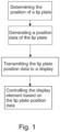
- FIG. 1 shows a block diagram of the new method for indicating a position of a lip plate of a bucket of a loading vehicle to an operator.
- the bucket of the loading vehicle is positioned and adjusted by tilting so that an angle in relation to horizontal level changes.
- the position of the lip plate of the bucket affects the efficiency of the operation.
- the loading vehicle comprises at least one bucket position sensor, which is used for determining the position of the lip plate.
- the bucket position sensor generates position data of the lip plate, and the position data is transmitted to a display comprising a display control unit and a display element. At least the display element is visible to the cockpit of the loading vehicle so that the operator may see the display element.
- the bucket position i.e.
- the bucket position sensor may be for example a linear sensor.
- the linear sensor may be arranged in a tilt cylinder of the loading vehicle, which tilt cylinder is configured to control the bucket, and the lip plate, position, e.g. angle in relation to the horizontal level.
- the loading vehicle may comprise lever or levers, e.g. swing lever or tilt lever, between the tilt cylinder and the bucket.
- the loading vehicle may comprise more than one tilt cylinder for controlling and adjusting the position of the bucket, and at least one of the tilt cylinders comprises a linear sensor as a bucket position sensor.
- the bucket position sensor may be a mechanical sensor (e.g. limit switch), inductive sensor, hall sensor, optical sensor (e.g. LIDAR or reflective sensor) or rotary angle sensor for determining the lip plate position, i.e. angle.
- a mechanical sensor e.g. limit switch
- inductive sensor e.g., inductive sensor
- hall sensor e.g., hall sensor
- optical sensor e.g. LIDAR or reflective sensor
- rotary angle sensor for determining the lip plate position, i.e. angle.
- the loading vehicle comprises an electronic control unit (ECU) which is adapted to receive and transmit the lip position data.
- ECU electronice control unit
- the lip position data may be received from the bucket position sensor to the ECU and transmitted from the ECU to the display.
- the ECU may have pre-stored lip plate position data, which may include for example specific angle or angles and/or angle range or ranges.
- the lip position data may be compared to the pre-stored lip position data.
- the lip position data which is transmitted from the ECU to the display control unit, may include the lip position comparison data.
- the controlling of the display element may be carried out with accordance of plurality of controlling options, wherein the selection of controlling option is based on the comparison data, i.e. what visual information should be seen on the display element depending on the position of the lip plate.
- the new method may be carried out for example with a system for indicating a position of a lip plate of a bucket of a loading vehicle to an operator.
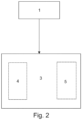
- Figure 2 shows the system comprising at least one bucket position sensor 1 arranged to determine the position of the lip plate and to generate a position data of the lip plate; a display 3 comprising a display element 4, which is visible to the cockpit of the loading vehicle for displaying the lip plate position to the operator inside the cockpit, and a display control unit 5.
- the display control unit 5 is configured to control the display element 4 for indicating the position of the lip plate, e.g. with the graphics or other visual elements shown on the display element, based on the lip plate position data.
- the display element 4 and the display control unit 5 of the display may be inside a same unit, such as a display unit, or they may be positioned separately and connected to each other for transmitting signal.
- the display element 4 may be fastened to a window of the cockpit or laminated inside or outside of the window of the cockpit.
- the display element 4 may be transparent for maximizing he visibility of the operator.
- the display element may be fastened to the window for example by adhesive.
- the display element 4 is arranged to project the lip position to a surface, e.g. to a window.
- the display element 4 may be arranged outside of the cockpit so that the operator in the cockpit may see it.
- the display element 4 may be fastened to a structure outside of the cockpit.
- the display element is arranged to a dashboard of the cockpit.
- the display element 4 is positioned so that it is visible when the bucket is used, e.g. during loading.
- the display element 4 is arranged between the operator and the bucket, when operator is inside the cockpit and operating the loading vehicle.
- the display element is arranged to the window of the cockpit, which window is towards the bucket.
- the display element may be for example a film display.
- the display element 4 comprises at least one light source, e.g. light bulb or LED, which indicates the position of the lip plate with color or by turning on and off.
- the display element 4 may comprise a frame or a housing.
- the display control unit 5 and the display element 4 of the display 3 may be inside the same unit, i.e. display unit.
- the display unit comprising the display element, may be arranged outside of the cockpit so that the operator in the cockpit may see it.
- the display unit may be fastened to a structure outside of the cockpit.
- the display unit is arranged to a dashboard of the cockpit.
- the display unit is positioned so that it is visible when the bucket is used, e.g. during loading.
- the display unit is arranged between the operator and the bucket, when the operator is inside the cockpit and operating the loading vehicle.
- the display unit is arranged to the window of the cockpit, which window is towards the bucket.
- the display element of the display unit may be for example a film display.
- the display element 4 comprises at least one light source, e.g. light bulb or LED, which indicates the position of the lip plate with color or by turning on and off.
- the display element 4 may comprise a frame or a housing.
- the bucket position sensor 1 may be a linear sensor, which may be arranged in connection with a tilt cylinder of the bucket. When the bucket is tilted, the linear sensor generates lip position data, which is transmitted either directly to the display or, optionally, to the ECU and further from the ECU to the display.
- the bucket position sensor 1 is a swivel angle sensor, mechanical sensor (e.g. limit switch), inductive sensor, hall sensor, optical sensor (e.g. LIDAR or reflective sensor) or rotary angle sensor for determining the lip plate position, i.e. angle.
- the loading vehicle comprises an electronic control unit (ECU) which is adapted to receive and transmit the lip position data.
- ECU electronice control unit
- the lip position data may be received from the bucket position sensor to the ECU and transmitted from the ECU to the display.
- the ECU 2 may comprise a storage medium for storing data.
- the stored data may be for example lip position data of the loading vehicle.
- the data may be pre-stored to the storage medium of the ECU.
- the ECU 2 may be adapted to compare the lip plate position data from the bucket position sensor to the pre-stored lip plate position data.
- the lip position data transmitted from the ECU to the display control unit may be the lip position comparison data or at least include the lip position comparison data.
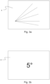
- Figures 3a and 3b show examples how the lip plate position may be displayed on the display element 4.
- the display element 4 is controlled so that it is arranged to display the position of the lip plate of the bucket.
- the position may be displayed for example as an actual angle of the lip plate (as shown in figure 3b ), as being on the desired or pre-stored angle or range, and/or as being off the desired or pre-stored angle or angle range.
- the lip plate position may be displayed on the display element as a numerical value of the actual angle, as a color indicator (e.g. green when the position is on desired range and red when the position is not on the desired range), as text, or as other visual indicator such as lines or other shapes (as shown in figure 3a ).
- the numerical values or other visual indicators may be colored as in the colored indicator above.
- the optimal position i.e. angle of the lip plate
- the ECU may pre-stored in the ECU, and if the actual position of the lip plate is the optimal position, it may be shown as constant line on the display. If the actual position of the lip plate differs from the optimal pre-stored value, the position of the lip plate may be shown as dashed line on the display element.
- the display element may display whether the actual lip plate position is more than optimal value or less than the optimal value for guiding the operator for adjusting the position of the bucket.
- the system may comprise means to display the bucket position in another display, for example outside of the loading vehicle.
- the another display may be for example a mobile phone, other movable display, or external display for example in a maintenance building or other building for displaying the bucket position outside of the loading vehicle.
- the another display may show a mirrored image or video of the display on the loading vehicle, or it may show additional information.
- the signal to the another display may be transmitted with conventional wires or with wireless technology by using for example WIFI or Bluetooth.
- FIG 4 shows an example of a bucket 10 of a loading vehicle.
- the bucket comprises a lip plate 11, which is arranged at the lower front horizontal edge of the bucket and is extending in width direction of the bucket. Further, the lip plate 11 extends outwards of the bucket body.
- Fig. 5 shows a bucket 10 of a loading vehicle and some alternative positions of the bucket and the lip plate 11.
- the fixed line illustrates the horizontal position
- the dashed lines illustrate some tilted positions of the bucket.
- Fig. 6 shows an example of a loading vehicle comprising a bucket 10 with a lip plate 11 and a cockpit 12.
- the cockpit comprises side walls and a roof, but, in optional embodiments of the loading vehicles, the cockpit may be without the side walls and the roof.
- Fig. 7 shows a loading vehicle comprising an example embodiment of the system for indicating the position of the lip plate of the bucket.
- the loading vehicle comprises a bucket 10 arranged on front part of the loading vehicle and a cockpit 15.
- the bucket comprises a lip plate 11.
- the bucket position, and the lip plate position is controlled and adjusted with a linear motion of a tilt cylinder 12, which tilt cylinder is connected to the bucket via swing lever 14 and a dog bone 16.
- the lip plate position is determined by a linear sensor 13, which is arranged in connection to the tilt cylinder 12, and the lip plate position data is generated.
- the lip plate position data is received to an ECU 2 and the lip position data is transmitted from the ECU to a display 3 comprising a display control unit and a display element.
- the ECU is an optional element, and the lip position data may be transmitted directly from the bucket position sensor to the display.
- the display 3 is fastened to a front window of the cockpit 15 so that at least the display element is visible to the operator inside the cockpit.
- the display element is controlled based on the lip position data, i.e. the lip position is shown on the display element so that the operator sees the lip plate position even if he does not see the actual lip plate.
- the bucket 10 is connected to the loading vehicle with a lift arm 17, which may be used to raise or lower the bucket.
- the position of the lift arm 17 may also be determined by another sensor, and the position data of the lift arm may be used for determining the lip plate position. For example, when the lift arm 17 is in its lowest position, i.e. the lift arm 17 is against stoppers on the loading vehicle, the lip plate position is what the bucket position sensor determines. However, when the lift arm 17 is lifted, i.e. the lift arm 17 is not against the stoppers, the lip plate position, in relation to the ground surface, may not be exactly what the bucket position sensor determines.
- the lift arm position data may be used to compensate the lip plate position data to show the actual position of the lip plate, in relation to the horizontal surface.
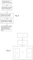
- FIG 8 shows a block diagram of the method of figure 1 with an additional step of transmitting the lip position data from the bucket position sensor to the display via an electronic control unit (ECU).
- ECU electronice control unit
- FIG. 9 shows a block diagram of the system as shown in figure 2 with an additional electronic control unit (ECU) 2, which is adapted to receive the lip position data from the bucket position sensor 1 and to transmit the lip position data to the display 3.
- ECU electronice control unit
Landscapes
- Engineering & Computer Science (AREA)
- Mining & Mineral Resources (AREA)
- Civil Engineering (AREA)
- General Engineering & Computer Science (AREA)
- Structural Engineering (AREA)
- Component Parts Of Construction Machinery (AREA)
Abstract
A method for indicating a position of a lip plate of a bucket of a loading vehicle to an operator inside a cockpit, comprising steps of:
a. determining the position of the lip plate of the bucket by using at least one bucket position sensor (1) and generating a position data of the lip plate of the bucket,
b. transmitting the lip plate position data from the bucket position sensor to a display (3), which comprises a display control unit (5) and a display element (4), wherein at least the display element is visible to the cockpit of the loading vehicle, and
c. controlling the display element (4) based on the lip plate position data to display visual information indicative of the lip plate position.
a. determining the position of the lip plate of the bucket by using at least one bucket position sensor (1) and generating a position data of the lip plate of the bucket,
b. transmitting the lip plate position data from the bucket position sensor to a display (3), which comprises a display control unit (5) and a display element (4), wherein at least the display element is visible to the cockpit of the loading vehicle, and
c. controlling the display element (4) based on the lip plate position data to display visual information indicative of the lip plate position.
Description
- The present disclosure relates to methods and systems for indicating position of a bucket of a loading vehicle, and especially the position of a lip plate of the bucket.
- Loading vehicles are big and robust vehicles that operate on the surface or underground. The environmental conditions in mines etc. are harsh and visibility is very limited. For example, it may be difficult to see the precise position of the bucket of the loading vehicle to the cockpit of the vehicle and, thus, there is possibility to crash to some obstacle. The visibility is also dependent on the physical size of the operator, which may affect the knowledge of the precise position of the bucket in relation to the surface. If the bucket is in wrong position, the loading vehicle may start to climb on the material instead of collecting it into the bucket, or the bucket may start to dig to the ground under the material.
- To help the operator to see the bucket position, it is known to use mechanical indicators that are fixed to the bucket so that the operator may see the indicators on the cockpit. However, these mechanical indicators are exposed to external impacts and forces, e.g. mine walls and rocks, and they may get hit. Thus, their position may change, or they may even come off resulting wrong information to the operator.
- The objective of the method and system is to alleviate the disadvantages mentioned above.
- According to a first aspect, it is provided a method for indicating a position of a lip plate of a bucket of a loading vehicle to an operator inside a cockpit, comprising steps of:
- a. determining the position of the lip plate of the bucket by using at least one bucket position sensor and generating a position data of the lip plate of the bucket,
- b. transmitting the lip plate position data from the bucket position sensor to a display, which comprises a display control unit and a display element, wherein at least the display element is visible to the cockpit of the loading vehicle, and
- c. controlling the display element based on the lip plate position data to display visual information indicative of the lip plate position.
- The advantage of the method is that the position of the lip plate of the bucket is provided to the operator in all conditions.
- In an embodiment of the method, the lip plate position data is transmitted from the bucket position sensor to the display via an electronic control unit (ECU) so that the ECU is receiving the lip plate position data from the bucket position sensor and transmitting the lip plate position data to the display.
- In an embodiment of the method, the lip plate position data from the bucket position sensor is compared to a lip plate position data pre-stored in the ECU.
- In an embodiment of the method, the position data transmitted from the ECU to the display comprises comparison data of the lip plate position in relation to the pre-stored lip plate position data.
- In an embodiment of the method, controlling is carried out with accordance of plurality of controlling options, wherein the selection of controlling option is based on the comparison data.
- According to a second aspect, it is provided a system for indicating a position of a lip plate of a bucket of a loading vehicle to an operator, comprising
- at least one bucket position sensor arranged to determine the position of the lip plate and to generate a position data of the lip plate; and
- a display comprising a display element and a display control unit, wherein at least the display element is visible to the cockpit of the loading vehicle for displaying the lip plate position to the operator;
- the lip plate position data is configured to be transmitted from the bucket position sensor to the display, and
- the display control unit is configured to control the display element based on the lip plate position data to display visual information indicative of the lip plate position.
- The advantage of the system is that the lip plate position may be seen in cockpit in real time and in any conditions.
- In an embodiment of the system, the system comprises an electronic control unit (ECU) adapted to
- receive the lip plate position data from the bucket position sensor, and
- transmit the lip plate position data to a display control unit.
- In an embodiment of the system, the display element is fastened to a window of the cockpit.
- In an embodiment of the system, the display element is laminated inside the window of the cockpit.
- In an embodiment of the system, the display element is transparent.
- In an embodiment of the system, the display element is fastened to the window of the cockpit with an adhesive.
- In an embodiment of the system, the display element is arranged outside of the cockpit fastened to a structure outside of the cockpit.
- In an embodiment of the system, the display element is arranged to project the lip position to a window.
- In an embodiment of the system, the bucket position sensor is a linear sensor.
- In an embodiment of the system, the linear sensor is arranged in connection with a tilt cylinder of the bucket.
- In an embodiment of the system, the ECU comprises a storage medium for storing the lip plate position data.
- In an embodiment of the system, the ECU is adapted to store lip plate position data of the loading vehicle, which data is pre-stored to the storage medium of the ECU.
- In an embodiment of the system, the ECU is adapted to compare the lip plate position data from the bucket position sensor to the pre-stored lip plate position data.
- According to a third aspect, it is provided a loading vehicle, comprising a system for indicating a position of a lip plate of a bucket of the loading vehicle to an operator.
- It is to be understood that the aspects and embodiments described above may be used in any combination with each other. Several of the aspects and embodiments may be combined together to form a further embodiment.
- The accompanying drawings, which are included to provide a further understanding of the method and system and constitute a part of this specification, illustrate embodiments and together with the description help to explain the principles of system and method. In the drawings:
-
Fig. 1 shows a block diagram of the new method, -
Fig. 2 shows the new system for indicating the lip plate position to the operator in a cockpit, -
Figs. 3a and 3b show examples of the displayed information on the display element, -
Fig. 4 shows an example of a bucket of a loading vehicle, -
Fig. 5 shows a bucket of a loading vehicle and some alternative positions of the bucket, -
Fig. 6 shows an example of a loading vehicle, -
Fig. 7 shows a loading vehicle comprising an example embodiment of the system for indicating the position of the lip plate of the bucket. -
Fig. 8 shows a block diagram as shown infigure 1 with an additional step of transmitting the lip position data from the bucket position sensor to the display via an electronic control unit (ECU), and -
Fig. 9 shows a block diagram as shown infigure 2 with an additional electronic control unit (ECU). - A loading vehicle with a bucket may be for example a loader or a loading machine configured to operate on the ground or underground. The underground vehicle may be for example a mining vehicle. Further, it comprises a means to adjust the position of the bucket, a cockpit for the operator, and, optionally, an electronic control unit (ECU) for controlling one or more electrical systems or subsystems in the loading vehicle. Adjusting the position of the bucket may mean, for example, tilting. The bucket comprises a lip plate which extends in width direction of the bucket and is arranged on the outermost edge of the bucket so that the lip plate engages with the collectable material first.
-
Figure 1 shows a block diagram of the new method for indicating a position of a lip plate of a bucket of a loading vehicle to an operator. During operation, the bucket of the loading vehicle is positioned and adjusted by tilting so that an angle in relation to horizontal level changes. Especially, the position of the lip plate of the bucket affects the efficiency of the operation. The loading vehicle comprises at least one bucket position sensor, which is used for determining the position of the lip plate. The bucket position sensor generates position data of the lip plate, and the position data is transmitted to a display comprising a display control unit and a display element. At least the display element is visible to the cockpit of the loading vehicle so that the operator may see the display element. The bucket position, i.e. the lip plate position, is indicated to the operator by controlling the display element based on the lip plate position data to display visual information indicative of the lip plate position, i.e. the display element is configured to indicate the lip plate position. The lip plate position may be indicated graphically, e.g. with shapes or colors, numerically, with text, or with other visual indicators. - The bucket position sensor may be for example a linear sensor. The linear sensor may be arranged in a tilt cylinder of the loading vehicle, which tilt cylinder is configured to control the bucket, and the lip plate, position, e.g. angle in relation to the horizontal level. The loading vehicle may comprise lever or levers, e.g. swing lever or tilt lever, between the tilt cylinder and the bucket. The loading vehicle may comprise more than one tilt cylinder for controlling and adjusting the position of the bucket, and at least one of the tilt cylinders comprises a linear sensor as a bucket position sensor.
- Optionally, the bucket position sensor may be a mechanical sensor (e.g. limit switch), inductive sensor, hall sensor, optical sensor (e.g. LIDAR or reflective sensor) or rotary angle sensor for determining the lip plate position, i.e. angle.
- Optionally, the loading vehicle comprises an electronic control unit (ECU) which is adapted to receive and transmit the lip position data. With the ECU, the lip position data may be received from the bucket position sensor to the ECU and transmitted from the ECU to the display.
- The ECU may have pre-stored lip plate position data, which may include for example specific angle or angles and/or angle range or ranges. When the lip position data is received from the bucket position sensor, the lip position data may be compared to the pre-stored lip position data. The lip position data, which is transmitted from the ECU to the display control unit, may include the lip position comparison data. The controlling of the display element may be carried out with accordance of plurality of controlling options, wherein the selection of controlling option is based on the comparison data, i.e. what visual information should be seen on the display element depending on the position of the lip plate.
- The new method may be carried out for example with a system for indicating a position of a lip plate of a bucket of a loading vehicle to an operator.
-
Figure 2 shows the system comprising at least onebucket position sensor 1 arranged to determine the position of the lip plate and to generate a position data of the lip plate; adisplay 3 comprising adisplay element 4, which is visible to the cockpit of the loading vehicle for displaying the lip plate position to the operator inside the cockpit, and adisplay control unit 5. Thedisplay control unit 5 is configured to control thedisplay element 4 for indicating the position of the lip plate, e.g. with the graphics or other visual elements shown on the display element, based on the lip plate position data. - The
display element 4 and thedisplay control unit 5 of the display may be inside a same unit, such as a display unit, or they may be positioned separately and connected to each other for transmitting signal. Thedisplay element 4 may be fastened to a window of the cockpit or laminated inside or outside of the window of the cockpit. Thedisplay element 4 may be transparent for maximizing he visibility of the operator. The display element may be fastened to the window for example by adhesive. Optionally, thedisplay element 4 is arranged to project the lip position to a surface, e.g. to a window. Optionally, thedisplay element 4 may be arranged outside of the cockpit so that the operator in the cockpit may see it. For example, thedisplay element 4 may be fastened to a structure outside of the cockpit. Optionally, the display element is arranged to a dashboard of the cockpit. Optionally or additionally, thedisplay element 4 is positioned so that it is visible when the bucket is used, e.g. during loading. For example, thedisplay element 4 is arranged between the operator and the bucket, when operator is inside the cockpit and operating the loading vehicle. Optionally, the display element is arranged to the window of the cockpit, which window is towards the bucket. The display element may be for example a film display. Optionally, thedisplay element 4 comprises at least one light source, e.g. light bulb or LED, which indicates the position of the lip plate with color or by turning on and off. Thedisplay element 4 may comprise a frame or a housing. - As described above, the
display control unit 5 and thedisplay element 4 of thedisplay 3 may be inside the same unit, i.e. display unit. The display unit, comprising the display element, may be arranged outside of the cockpit so that the operator in the cockpit may see it. For example, the display unit may be fastened to a structure outside of the cockpit. Optionally, the display unit is arranged to a dashboard of the cockpit. Optionally or additionally, the display unit is positioned so that it is visible when the bucket is used, e.g. during loading. For example, the display unit is arranged between the operator and the bucket, when the operator is inside the cockpit and operating the loading vehicle. Optionally, the display unit is arranged to the window of the cockpit, which window is towards the bucket. The display element of the display unit may be for example a film display. Optionally, thedisplay element 4 comprises at least one light source, e.g. light bulb or LED, which indicates the position of the lip plate with color or by turning on and off. Thedisplay element 4 may comprise a frame or a housing. - The
bucket position sensor 1 may be a linear sensor, which may be arranged in connection with a tilt cylinder of the bucket. When the bucket is tilted, the linear sensor generates lip position data, which is transmitted either directly to the display or, optionally, to the ECU and further from the ECU to the display. Optionally, thebucket position sensor 1 is a swivel angle sensor, mechanical sensor (e.g. limit switch), inductive sensor, hall sensor, optical sensor (e.g. LIDAR or reflective sensor) or rotary angle sensor for determining the lip plate position, i.e. angle. - Optionally, the loading vehicle comprises an electronic control unit (ECU) which is adapted to receive and transmit the lip position data. With the ECU, the lip position data may be received from the bucket position sensor to the ECU and transmitted from the ECU to the display.
- The
ECU 2 may comprise a storage medium for storing data. The stored data may be for example lip position data of the loading vehicle. The data may be pre-stored to the storage medium of the ECU. - The
ECU 2 may be adapted to compare the lip plate position data from the bucket position sensor to the pre-stored lip plate position data. The lip position data transmitted from the ECU to the display control unit may be the lip position comparison data or at least include the lip position comparison data. -
Figures 3a and 3b show examples how the lip plate position may be displayed on thedisplay element 4. Thedisplay element 4 is controlled so that it is arranged to display the position of the lip plate of the bucket. The position may be displayed for example as an actual angle of the lip plate (as shown infigure 3b ), as being on the desired or pre-stored angle or range, and/or as being off the desired or pre-stored angle or angle range. The lip plate position may be displayed on the display element as a numerical value of the actual angle, as a color indicator (e.g. green when the position is on desired range and red when the position is not on the desired range), as text, or as other visual indicator such as lines or other shapes (as shown infigure 3a ). The numerical values or other visual indicators may be colored as in the colored indicator above. For example, the optimal position, i.e. angle of the lip plate, may be pre-stored in the ECU, and if the actual position of the lip plate is the optimal position, it may be shown as constant line on the display. If the actual position of the lip plate differs from the optimal pre-stored value, the position of the lip plate may be shown as dashed line on the display element. The display element may display whether the actual lip plate position is more than optimal value or less than the optimal value for guiding the operator for adjusting the position of the bucket. - The system may comprise means to display the bucket position in another display, for example outside of the loading vehicle. The another display may be for example a mobile phone, other movable display, or external display for example in a maintenance building or other building for displaying the bucket position outside of the loading vehicle. The another display may show a mirrored image or video of the display on the loading vehicle, or it may show additional information. The signal to the another display may be transmitted with conventional wires or with wireless technology by using for example WIFI or Bluetooth.
-
Figure 4 shows an example of abucket 10 of a loading vehicle. The bucket comprises alip plate 11, which is arranged at the lower front horizontal edge of the bucket and is extending in width direction of the bucket. Further, thelip plate 11 extends outwards of the bucket body. -
Fig. 5 shows abucket 10 of a loading vehicle and some alternative positions of the bucket and thelip plate 11. The fixed line illustrates the horizontal position, and the dashed lines illustrate some tilted positions of the bucket. -
Fig. 6 shows an example of a loading vehicle comprising abucket 10 with alip plate 11 and acockpit 12. Infigure 6 , the cockpit comprises side walls and a roof, but, in optional embodiments of the loading vehicles, the cockpit may be without the side walls and the roof. -
Fig. 7 shows a loading vehicle comprising an example embodiment of the system for indicating the position of the lip plate of the bucket. The loading vehicle comprises abucket 10 arranged on front part of the loading vehicle and acockpit 15. The bucket comprises alip plate 11. The bucket position, and the lip plate position, is controlled and adjusted with a linear motion of atilt cylinder 12, which tilt cylinder is connected to the bucket viaswing lever 14 and adog bone 16. The lip plate position is determined by alinear sensor 13, which is arranged in connection to thetilt cylinder 12, and the lip plate position data is generated. Infigure 7 , the lip plate position data is received to anECU 2 and the lip position data is transmitted from the ECU to adisplay 3 comprising a display control unit and a display element. As mentioned earlier, the ECU is an optional element, and the lip position data may be transmitted directly from the bucket position sensor to the display. Thedisplay 3 is fastened to a front window of thecockpit 15 so that at least the display element is visible to the operator inside the cockpit. The display element is controlled based on the lip position data, i.e. the lip position is shown on the display element so that the operator sees the lip plate position even if he does not see the actual lip plate. - The
bucket 10 is connected to the loading vehicle with alift arm 17, which may be used to raise or lower the bucket. The position of thelift arm 17 may also be determined by another sensor, and the position data of the lift arm may be used for determining the lip plate position. For example, when thelift arm 17 is in its lowest position, i.e. thelift arm 17 is against stoppers on the loading vehicle, the lip plate position is what the bucket position sensor determines. However, when thelift arm 17 is lifted, i.e. thelift arm 17 is not against the stoppers, the lip plate position, in relation to the ground surface, may not be exactly what the bucket position sensor determines. The lift arm position data may be used to compensate the lip plate position data to show the actual position of the lip plate, in relation to the horizontal surface. -
Figure 8 shows a block diagram of the method offigure 1 with an additional step of transmitting the lip position data from the bucket position sensor to the display via an electronic control unit (ECU). -
Figure 9 shows a block diagram of the system as shown infigure 2 with an additional electronic control unit (ECU) 2, which is adapted to receive the lip position data from thebucket position sensor 1 and to transmit the lip position data to thedisplay 3.
Claims (19)
- A method for indicating a position of a lip plate of a bucket of a loading vehicle to an operator inside a cockpit, comprising steps of:a. determining the position of the lip plate of the bucket by using at least one bucket position sensor (1) and generating a position data of the lip plate of the bucket,b. transmitting the lip plate position data from the bucket position sensor to a display (3), which comprises a display control unit (5) and a display element (4), wherein at least the display element is visible to the cockpit of the loading vehicle, andc. controlling the display element (4) based on the lip plate position data to display visual information indicative of the lip plate position.
- The method according to claim 1, wherein the lip plate position data is transmitted from the bucket position sensor to the display via an electronic control unit (ECU) so that the ECU is receiving the lip plate position data from the bucket position sensor (1) and transmitting the lip plate position data to the display (3) .
- The method according to claim 2, wherein
the lip plate position data from the bucket position sensor is compared to a lip plate position data pre-stored in the ECU (2). - The method according to claim 2, wherein the position data transmitted from the ECU to the display comprises comparison data of the lip plate position in relation to the pre-stored lip plate position data.
- The method according to claim 4, wherein in step c., controlling is carried out with accordance of plurality of controlling options, wherein the selection of controlling option is based on the comparison data.
- A system for indicating a position of a lip plate of a bucket of a loading vehicle to an operator, comprising- at least one bucket position sensor (1) arranged to determine the position of the lip plate and to generate a position data of the lip plate; and- a display (3) comprising a display element (4) and a display control unit (5), wherein at least the display element (4) is visible to the cockpit of the loading vehicle for displaying the lip plate position to the operator;whereinthe lip plate position data is configured to be transmitted from the bucket position sensor (1) to the display (3), andthe display control unit (5) is configured to control the display element (4) based on the lip plate position data to display visual information indicative of the lip plate position.
- The system according to claim 6, wherein the system comprises an electronic control unit (ECU) (2) adapted to- receive the lip plate position data from the bucket position sensor (1), and- transmit the lip plate position data to a display control unit (5).
- The system according to claim 6 or 7, wherein the display element (4) is fastened to a window of the cockpit.
- The system according to any one of claims 6 to 8, wherein the display element (4) is laminated inside the window of the cockpit.
- The system according to any one of claims 6 to 9, wherein the display element (4) is transparent.
- The system according to any one of claims 6 to 10, wherein the display element (4) is fastened to the window of the cockpit with an adhesive.
- The system according to claim 6 or 7, wherein the display element (4) is arranged outside of the cockpit, and it is fastened to a structure outside of the cockpit.
- The system according to any one of claims 6 to 12, wherein the display element (4) is arranged to project the lip position to a window.
- The system according to any one of claims 6 to 13, wherein the bucket position sensor (1) is a linear sensor.
- The system according to claim 14, wherein the linear sensor (1) is arranged in connection with a tilt cylinder of the bucket.
- The system according to any one of claims 7 to 15, wherein the ECU (2) comprises a storage medium for storing the lip plate position data.
- The system according to claim 16, wherein the ECU (2) is adapted to store lip plate position data of the loading vehicle, which data is pre-stored to the storage medium of the ECU.
- The system according to claim 17, wherein the ECU (2) is adapted to compare the lip plate position data from the bucket position sensor (1) to the pre-stored lip plate position data.
- A loading vehicle, comprising a system according to any one of claims 6 to 18.
Priority Applications (1)
| Application Number | Priority Date | Filing Date | Title |
|---|---|---|---|
| EP23197563.2A EP4524331A1 (en) | 2023-09-15 | 2023-09-15 | A method and a system for indicating a lip plate position |
Applications Claiming Priority (1)
| Application Number | Priority Date | Filing Date | Title |
|---|---|---|---|
| EP23197563.2A EP4524331A1 (en) | 2023-09-15 | 2023-09-15 | A method and a system for indicating a lip plate position |
Publications (1)
| Publication Number | Publication Date |
|---|---|
| EP4524331A1 true EP4524331A1 (en) | 2025-03-19 |
Family
ID=88092962
Family Applications (1)
| Application Number | Title | Priority Date | Filing Date |
|---|---|---|---|
| EP23197563.2A Withdrawn EP4524331A1 (en) | 2023-09-15 | 2023-09-15 | A method and a system for indicating a lip plate position |
Country Status (1)
| Country | Link |
|---|---|
| EP (1) | EP4524331A1 (en) |
Citations (4)
| Publication number | Priority date | Publication date | Assignee | Title |
|---|---|---|---|---|
| EP3214229A1 (en) * | 2014-10-27 | 2017-09-06 | Yanmar Co., Ltd. | Work vehicle |
| EP3361008A2 (en) * | 2017-02-08 | 2018-08-15 | Deere & Company | System and method for remote work implement angular position display |
| US20210138969A1 (en) * | 2019-11-12 | 2021-05-13 | Clark Equipment Company | Display integrated into door |
| JP2022161283A (en) * | 2021-04-08 | 2022-10-21 | 株式会社小松製作所 | Position estimation system, position estimation unit, work machine, and extension unit |
-
2023
- 2023-09-15 EP EP23197563.2A patent/EP4524331A1/en not_active Withdrawn
Patent Citations (4)
| Publication number | Priority date | Publication date | Assignee | Title |
|---|---|---|---|---|
| EP3214229A1 (en) * | 2014-10-27 | 2017-09-06 | Yanmar Co., Ltd. | Work vehicle |
| EP3361008A2 (en) * | 2017-02-08 | 2018-08-15 | Deere & Company | System and method for remote work implement angular position display |
| US20210138969A1 (en) * | 2019-11-12 | 2021-05-13 | Clark Equipment Company | Display integrated into door |
| JP2022161283A (en) * | 2021-04-08 | 2022-10-21 | 株式会社小松製作所 | Position estimation system, position estimation unit, work machine, and extension unit |
Similar Documents
| Publication | Publication Date | Title |
|---|---|---|
| US10036141B2 (en) | Control system for work vehicle, control method and work vehicle | |
| KR102573390B1 (en) | shovel | |
| US9030332B2 (en) | Method and apparatus for generating an indication of an object within an operating ambit of heavy loading equipment | |
| EP2524085B1 (en) | System for orienting an implement on a vehicle | |
| KR102493019B1 (en) | Shovel, shovel display device and shovel display method | |
| KR100934947B1 (en) | Image display system of heavy equipment equipped with leveling means | |
| US8280621B2 (en) | Vehicle collision avoidance system | |
| US9702121B2 (en) | State information display for work machine, caution-sign displaying method for work machine, and caution-sign displaying program for work machine | |
| KR102615982B1 (en) | Shovel and shovel management system | |
| KR20200038884A (en) | Shovel and shovel support device | |
| KR20230162598A (en) | Display control system for working machines, display system for working machines, working machine, display control method for working machines and display control program for working machines | |
| US20250003202A1 (en) | Display device for excavator, display device for work machine, and monitor system of excavator | |
| KR20220097482A (en) | Working Machines and Control Methods of Working Machines | |
| CA2781349C (en) | Method and apparatus for generating an indication of an object within an operating ambit of heavy loading equipment | |
| US20240424896A1 (en) | Work vehicle having speed and/or distance based decision support and intervention zones | |
| US20250075470A1 (en) | Work machine | |
| US20250215663A1 (en) | Excavator, display apparatus, and remote operation assistance apparatus | |
| US12624527B2 (en) | Work machine and remote operation support device | |
| AU2010355231A1 (en) | Method and control unit for controlling a display of a proximity warning system | |
| US20240328123A1 (en) | System and method of controlling construction machinery | |
| JP2000356164A (en) | Tractor | |
| US20260125873A1 (en) | Excavator | |
| EP4610441A1 (en) | Work information indication device and work machine comprising same | |
| EP4621144A1 (en) | Construction equipment display system | |
| EP4541972A1 (en) | Calibration system for spatial recognition devices for work machine, and work machine |
Legal Events
| Date | Code | Title | Description |
|---|---|---|---|
| PUAI | Public reference made under article 153(3) epc to a published international application that has entered the european phase |
Free format text: ORIGINAL CODE: 0009012 |
|
| STAA | Information on the status of an ep patent application or granted ep patent |
Free format text: STATUS: THE APPLICATION HAS BEEN PUBLISHED |
|
| AK | Designated contracting states |
Kind code of ref document: A1 Designated state(s): AL AT BE BG CH CY CZ DE DK EE ES FI FR GB GR HR HU IE IS IT LI LT LU LV MC ME MK MT NL NO PL PT RO RS SE SI SK SM TR |
|
| STAA | Information on the status of an ep patent application or granted ep patent |
Free format text: STATUS: THE APPLICATION IS DEEMED TO BE WITHDRAWN |
|
| 18D | Application deemed to be withdrawn |
Effective date: 20250920 |