EP4524313A1 - Dryer accessory and dryer - Google Patents
Dryer accessory and dryer Download PDFInfo
- Publication number
- EP4524313A1 EP4524313A1 EP22948071.0A EP22948071A EP4524313A1 EP 4524313 A1 EP4524313 A1 EP 4524313A1 EP 22948071 A EP22948071 A EP 22948071A EP 4524313 A1 EP4524313 A1 EP 4524313A1
- Authority
- EP
- European Patent Office
- Prior art keywords
- dryer
- sensor
- accessory
- pipe
- housing
- Prior art date
- Legal status (The legal status is an assumption and is not a legal conclusion. Google has not performed a legal analysis and makes no representation as to the accuracy of the status listed.)
- Pending
Links
Images



Classifications
-
- D—TEXTILES; PAPER
- D06—TREATMENT OF TEXTILES OR THE LIKE; LAUNDERING; FLEXIBLE MATERIALS NOT OTHERWISE PROVIDED FOR
- D06F—LAUNDERING, DRYING, IRONING, PRESSING OR FOLDING TEXTILE ARTICLES
- D06F34/00—Details of control systems for washing machines, washer-dryers or laundry dryers
- D06F34/04—Signal transfer or data transmission arrangements
- D06F34/05—Signal transfer or data transmission arrangements for wireless communication between components, e.g. for remote monitoring or control
-
- D—TEXTILES; PAPER
- D06—TREATMENT OF TEXTILES OR THE LIKE; LAUNDERING; FLEXIBLE MATERIALS NOT OTHERWISE PROVIDED FOR
- D06F—LAUNDERING, DRYING, IRONING, PRESSING OR FOLDING TEXTILE ARTICLES
- D06F58/00—Domestic laundry dryers
- D06F58/32—Control of operations performed in domestic laundry dryers
- D06F58/34—Control of operations performed in domestic laundry dryers characterised by the purpose or target of the control
- D06F58/36—Control of operational steps, e.g. for optimisation or improvement of operational steps depending on the condition of the laundry
- D06F58/38—Control of operational steps, e.g. for optimisation or improvement of operational steps depending on the condition of the laundry of drying, e.g. to achieve the target humidity
-
- D—TEXTILES; PAPER
- D06—TREATMENT OF TEXTILES OR THE LIKE; LAUNDERING; FLEXIBLE MATERIALS NOT OTHERWISE PROVIDED FOR
- D06F—LAUNDERING, DRYING, IRONING, PRESSING OR FOLDING TEXTILE ARTICLES
- D06F34/00—Details of control systems for washing machines, washer-dryers or laundry dryers
- D06F34/10—Power supply arrangements, e.g. stand-by circuits
-
- D—TEXTILES; PAPER
- D06—TREATMENT OF TEXTILES OR THE LIKE; LAUNDERING; FLEXIBLE MATERIALS NOT OTHERWISE PROVIDED FOR
- D06F—LAUNDERING, DRYING, IRONING, PRESSING OR FOLDING TEXTILE ARTICLES
- D06F34/00—Details of control systems for washing machines, washer-dryers or laundry dryers
- D06F34/14—Arrangements for detecting or measuring specific parameters
- D06F34/26—Condition of the drying air, e.g. air humidity or temperature
-
- D—TEXTILES; PAPER
- D06—TREATMENT OF TEXTILES OR THE LIKE; LAUNDERING; FLEXIBLE MATERIALS NOT OTHERWISE PROVIDED FOR
- D06F—LAUNDERING, DRYING, IRONING, PRESSING OR FOLDING TEXTILE ARTICLES
- D06F58/00—Domestic laundry dryers
- D06F58/20—General details of domestic laundry dryers
-
- D—TEXTILES; PAPER
- D06—TREATMENT OF TEXTILES OR THE LIKE; LAUNDERING; FLEXIBLE MATERIALS NOT OTHERWISE PROVIDED FOR
- D06F—LAUNDERING, DRYING, IRONING, PRESSING OR FOLDING TEXTILE ARTICLES
- D06F58/00—Domestic laundry dryers
- D06F58/20—General details of domestic laundry dryers
- D06F58/24—Condensing arrangements
-
- D—TEXTILES; PAPER
- D06—TREATMENT OF TEXTILES OR THE LIKE; LAUNDERING; FLEXIBLE MATERIALS NOT OTHERWISE PROVIDED FOR
- D06F—LAUNDERING, DRYING, IRONING, PRESSING OR FOLDING TEXTILE ARTICLES
- D06F58/00—Domestic laundry dryers
- D06F58/20—General details of domestic laundry dryers
- D06F58/26—Heating arrangements, e.g. gas heating equipment
-
- D—TEXTILES; PAPER
- D06—TREATMENT OF TEXTILES OR THE LIKE; LAUNDERING; FLEXIBLE MATERIALS NOT OTHERWISE PROVIDED FOR
- D06F—LAUNDERING, DRYING, IRONING, PRESSING OR FOLDING TEXTILE ARTICLES
- D06F2103/00—Parameters monitored or detected for the control of domestic laundry washing machines, washer-dryers or laundry dryers
- D06F2103/28—Air properties
- D06F2103/32—Temperature
-
- D—TEXTILES; PAPER
- D06—TREATMENT OF TEXTILES OR THE LIKE; LAUNDERING; FLEXIBLE MATERIALS NOT OTHERWISE PROVIDED FOR
- D06F—LAUNDERING, DRYING, IRONING, PRESSING OR FOLDING TEXTILE ARTICLES
- D06F2103/00—Parameters monitored or detected for the control of domestic laundry washing machines, washer-dryers or laundry dryers
- D06F2103/28—Air properties
- D06F2103/34—Humidity
-
- D—TEXTILES; PAPER
- D06—TREATMENT OF TEXTILES OR THE LIKE; LAUNDERING; FLEXIBLE MATERIALS NOT OTHERWISE PROVIDED FOR
- D06F—LAUNDERING, DRYING, IRONING, PRESSING OR FOLDING TEXTILE ARTICLES
- D06F2105/00—Systems or parameters controlled or affected by the control systems of washing machines, washer-dryers or laundry dryers
- D06F2105/56—Remaining operation time; Remaining operational cycles
-
- D—TEXTILES; PAPER
- D06—TREATMENT OF TEXTILES OR THE LIKE; LAUNDERING; FLEXIBLE MATERIALS NOT OTHERWISE PROVIDED FOR
- D06F—LAUNDERING, DRYING, IRONING, PRESSING OR FOLDING TEXTILE ARTICLES
- D06F58/00—Domestic laundry dryers
- D06F58/02—Domestic laundry dryers having dryer drums rotating about a horizontal axis
- D06F58/04—Details
Definitions
- the present disclosure relates to a dryer accessory and a dryer.
- a laundry treating apparatus may include a washing machine, a dryer, a styler, and the like, and the washing machine may have a drying function.
- the dryers are categorized into an exhaust-type dryer and a circulation-type dryer, which both heat air with a heater to produce hot air and dry laundry by exposing hot air to the laundry.
- an administration time may be determined simply based on a washing course and a weight of the laundry loaded into a drum, but in the dryer, not only a drying course and the weight of the laundry but also a degree of wetness of the laundry may affect the administration time.
- the humidity sensor or the temperature sensor may be installed in a cabinet or a duct to measure the humidity or a temperature.
- this external placement results in a temperature discrepancy between the sensor and the laundry within the drum and inaccurate measurement of the actual degree of wetness of the laundry.
- the present disclosure is to provide an accessory that may sense humidity and temperature of laundry without separate battery replacement and charging.
- a dryer accessory including a housing including a sensor hole, a sensor module that is located inside the sensor hole of the housing and measures at least one of temperature and humidity, an energy harvesting module that is located inside the housing and generates current based on a movement of the housing, a wireless communication module that transmits the at least one of the temperature and the humidity measured by the sensor module, and a controller that controls the sensor module and the wireless communication module using energy generated by the energy harvesting unit.
- the energy harvesting unit may include a pipe extending in one direction, a magnet positioned inside the pipe, and a coil wound on an outer surface of the pipe, and when the magnet moves in the extension direction of the pipe as the housing moves, the current may be generated in the coil.
- the magnet may have a cylindrical shape with a diameter smaller than an inner diameter of the pipe.
- the energy harvesting unit may include a pipe extending in one direction, a weight positioned inside the pipe, and a piezo disk positioned at an end of the pipe, and when the weight collides with the piezo disk, the current may be generated in the piezo disk.
- the controller may include a main board located inside the housing, and the pipe may extend through the main board.
- the pipe may extend vertically to the main board, wherein the pipe may include a plurality of pipes arranged along a circumference of the main board.
- the controller may include a rectifier that converts AC power generated from the energy harvesting module into DC power, a capacitor that stores energy converted into the DC power, and an analog-to-digital converter that deactivates the sensor module and the wireless communication module until an amount of the energy converted into DC power becomes sufficient to operate the sensor module and the wireless communication module.
- the dryer accessory may further include a cylindrical rubber plug positioned between the sensor module and the sensor hole, and a waterproof filter formed at a location of the rubber plug adjacent to the sensor hole, wherein the waterproof filter does not allow liquid to pass therethrough.
- the sensor hole and the sensor module may respectively include a pair of sensor holes and a pair of sensor modules disposed at opposite sides of the housing.
- the housing may contain an elastic material.
- the housing may have a spherical shape.
- a dryer for drying laundry includes a cabinet forming an outer appearance of the dryer, a drum rotatably disposed in the cabinet to accommodate the laundry therein, a driver that rotates the drum, a hot air supply that is in communication with the drum and supplies high-temperature air into the drum, a collector in communication with the hot air supply to collect water formed by condensation of moisture discharged from the drum, a wireless communication module that transmits and receives state information of the dryer, and a controller that controls the driver, the hot air supply, and the wireless communication module, the wireless communication module receives at least one of humidity information and temperature information provided by a dryer accessory inserted into the drum, and the controller controls the driver and the hot air supply using the at least one of the humidity information and the temperature information.
- the controller may terminate operations of the driver and the hot air supply when the temperature information and the humidity information reach a reference value.
- the dryer may further include at least one of a temperature sensor and a humidity sensor located inside the cabinet, and the controller may deactivate the at least one of the temperature sensor and the humidity sensor when there is the temperature information or the humidity information received from the dryer accessory.
- the temperature and the humidity of the laundry may be accurately measured via the dryer accessory.
- the dryer accessory may be used continuously without the separate battery replacement, so that the maintenance thereof may be easy and the damage to the product resulted from the poor waterproof function may be prevented.
- a dryer 10 of the present disclosure may be equipped as one of a washing machine that may dry laundry, a dryer that dries the laundry, and a styler that may prevent wrinkles and removing odors from the laundry.
- a following description is based on the dryer 10 being equipped as the dryer, but this is merely an embodiment and does not exclude the dryer 10 being equipped as the washing machine or the styler.
- FIG. 1 shows an outer appearance of the dryer 10 of the present disclosure.
- the dryer 10 of the present disclosure may include a cabinet 100 forming the outer appearance thereof, a control panel 120 coupled to the cabinet to input an operation command or display a state, a door 150 pivotably coupled to a front portion of the cabinet 100 to open and close a cabinet inlet through which the laundry is introduced, and a condensate accommodation container 110 where condensate is collected.
- the control panel 120 may be coupled to an upper end of the cabinet 100, may include therein a controller P including a microcomputer that controls the dryer, and may include a display 121 that displays the state of the dryer and an input unit that inputs a command to the controller.
- a controller P including a microcomputer that controls the dryer
- a display 121 that displays the state of the dryer and an input unit that inputs a command to the controller.
- the display 121 may be formed as a display screen such as an LCD or an LED, and may also be formed as a touch panel that may receive the command.
- the display 121 may accurately convey information on the dryer to a user by externally displaying an operating state and an abnormal state of the dryer.
- the display 121 may further include a speaker so as to emit an alarm sound to the user.
- the input unit may be formed as a rotary knob 122 to allow selection of an arbitrary drying course or option of the dryer.
- the input unit may include a power input unit 140 for supplying power to the dryer, and a command input unit 130 for inputting a separate control command.
- the power input unit 140 and the command input unit 130 may be formed as physical buttons so that the command may be transmitted even when power is not supplied to the display 121.
- the command input unit 130 may include a defrosting command input unit that transmits a defrosting command to the controller of the control panel 120 when the dryer 10 is frozen.
- the door 150 may be pivotably disposed at the front portion of the cabinet 100, and may be made of a transparent material such that the cabinet inlet defined in the cabinet may be seen through.
- the door 150 may have a handle 151 at one side, and may be coupled with a hinge 152 at the other side to open and close the cabinet inlet of the cabinet.
- FIG. 1 discloses the front-load type dryer with the door 150 disposed at the front, but a top-load type dryer with the door 150 disposed at the top is not excluded.
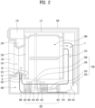
- FIG. 2 shows an internal structure of the dryer 10 of the present disclosure.
- the dryer 10 of the present disclosure may include a drum 200 rotatably disposed inside the cabinet 100 to accommodate the laundry therein, a driver 300 that rotates the drum 200, a hot air supply 400 that is in communication with the drum and supplies high-temperature air (hot air) into the drum, and a base 500 in which the hot air supply 400 is supported or installed.
- a drum 200 rotatably disposed inside the cabinet 100 to accommodate the laundry therein
- a driver 300 that rotates the drum 200
- a hot air supply 400 that is in communication with the drum and supplies high-temperature air (hot air) into the drum
- a base 500 in which the hot air supply 400 is supported or installed.
- the drum 200 may include a drum inlet 220 that is in communication with the cabinet inlet of the cabinet 100 and allows the laundry to be introduced and withdrawn therethrough, may be formed in a cylindrical shape that accommodates the laundry therein, and may include a lifter 210 that may raise and lower the laundry in a vertical direction to stir the laundry.
- the dryer 10 of the present disclosure may further include a gasket 230 that prevents the laundry from being withdrawn to a space between the cabinet inlet of the cabinet 100 and the drum inlet 220 of the drum 200.
- the hot air supply 400 may include a discharge duct 411 that is in communication with one side of the drum 200 so that moisture in the laundry and air that has passed through the laundry are discharged from the drum 200, a heat pump 420 that cools air that has passed through the discharge duct 411 to remove moisture therefrom and reheat air, and a suction duct 412 that sucks air that has passed through the heat pump back into the drum 200.
- the gasket 230 may include a duct connection hole 231 that is in communication with the suction duct 412.
- the heat pump 420 may include an evaporator 422 that cools air that has passed through the discharge duct 411, a compressor 421 that compresses and heats a refrigerant that has passed through the evaporator, a condenser 423 that heats air with the refrigerant that has passed through the compressor 421 to generate high-temperature dry hot air, and an expansion valve 424 that expands the refrigerant that has passed through the condenser 423 to reduce a temperature.
- an evaporator 422 that cools air that has passed through the discharge duct 411
- a compressor 421 that compresses and heats a refrigerant that has passed through the evaporator
- a condenser 423 that heats air with the refrigerant that has passed through the compressor 421 to generate high-temperature dry hot air
- an expansion valve 424 that expands the refrigerant that has passed through the condenser 423 to reduce a temperature.
- the base 500 may support the heat pump 420 while forming a bottom surface of the dryer 10.
- the base 500 may have one end in communication with the discharge duct 411 and the other end in communication with the suction duct 412, and may have the heat pump 420 installed therein and allow air to pass therethrough. Accordingly, water condensed in the evaporator 422 may be collected in the base 500, and a drainage pump 430 for discharging the collected water may be installed in the base 500.
- a collector 534 where the condensate is collected may be disposed at a lower portion of the base 500, and the drainage pump 430 may drain the condensate in the collector 534.
- the drainage pump 430 may be equipped to transfer collected water to the condensate accommodation container 110, and the condensate accommodation container 110 and the drainage pump 430 may be connected to each other via an accommodation pipe 111.
- the driver 300 may rotate the drum 200.
- the driver 300 may include a driving motor 310 that provides power to rotate the drum 200, a driving rotation shaft 320 that rotates by extending through the driving motor 310, a pulley 330 that is coupled to one end of the driving rotation shaft 320, and a belt 340 that is formed as a closed curve connecting the pulley 330 with an outer circumferential surface of the drum 200.
- the driver 300 may further include a blower fan 425 that is coupled to the other end of the driving rotation shaft 320 and provides power to circulate air inside the hot air supply 400 and the drum 200.
- the blower fan 425 may be installed in the hot air supply 400 or installed in a location of the base 500 that is in communication with the hot air supply 400 to circulate air in the drum 200 and the hot air supply 400.
- the drum 200 may rotate, and at the same time, the blower fan 425 may also circulate air in the drum 200.
- the blower fan 425 may cause air inside the drum 200 to pass through the discharge duct 411 in a direction I, then pass through the base 500 and the hot air supply 400, and then flow into the suction duct 412 in a direction II.
- the dryer 10 of the present disclosure may be equipped with a temperature sensor S1 that senses a temperature of air that has passed through the drum 200 or the hot air supply 400.
- the temperature sensor S1 may be disposed in the hot air supply 400.
- the temperature sensor S1 may be disposed in the suction duct 412.
- the temperature sensor S1 disposed in the suction duct 412 may sense a temperature change of air that has passed through the condenser 423. Accordingly, not only a temperature change of air inside the drum 200, but also a dried state of the laundry and an operating state of the heat pump 420 may be comprehensively checked via the temperature sensor S1.
- a humidity sensor S2 as a device for measuring residual moisture of the laundry, may accurately identify the dried state of the laundry only when it comes into direct contact with the laundry. Because the drum rotates, when an electronic component is installed on an inner wall of the drum, there are problems such as wiring, so that the humidity sensor may be disposed on an inner surface of a lower portion of the gasket 230 of the drum inlet.
- the temperature sensor is an important factor in determining the humidity, and it is difficult for the temperature sensor S1 located in the suction duct or the discharge duct to accurately measure the humidity because of a difference from a temperature of the laundry itself.
- the present disclosure uses a separate dryer accessory equipped with a sensor module that may measure the humidity, for more accurate humidity measurement.
- the sensor module may additionally be equipped with a temperature sensor to measure the temperature as well as the humidity.
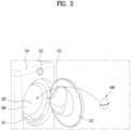
- FIG. 3 is a view showing a method for inserting a dryer accessory of the present disclosure into a dryer.
- the dryer accessory of the present disclosure is inserted into the dryer drum and is located inside the drum together with the laundry. Because the dryer accessory is located inside the drum and is able to be in direct contact with the laundry, the accurate temperature and humidity sensing becomes available.
- a ball dryer accessory inserted into the dryer drum may not necessarily have a ball shape, but may have a spherical shape to rotate with the rotation of the drum and minimize friction with the laundry.
- the dryer accessory prevents the pieces of laundry from tangling with each other when rotating in the drum and has an excellent dust removal effect by tapping the laundry. clothes.
- the dryer accessory creates a space between the pieces of laundry to improve a drying effect and shorten a drying time, resulting in an energy saving effect.
- the dryer accessory of the present disclosure may assist the function of the dryer by including a humidity sensor in addition to the physical action described above.
- a temperature sensor may also be disposed, and the dryer accessory may collect accurate humidity information and temperature information by being in direct contact with the laundry.
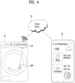
- FIG. 4 is a conceptual diagram showing a wireless communication flow between a dryer, a cloud server, and a user terminal of the present disclosure.
- the temperature information and the humidity information collected from the dryer accessory may be transmitted to the dryer via a wireless communication unit to adjust an administration time of the dryer.
- the wireless communication unit of the dryer may transmit the temperature information and the humidity information to a cloud server 20 and retransmit them to a user's terminal 30.
- FIG. 5 is an exploded view according to an embodiment of a dryer accessory of the present disclosure
- FIG. 6 is a cross-sectional view according to an embodiment of a dryer accessory of the present disclosure showing a sensor module.
- the dryer accessory of the present disclosure includes a housing having a space for mounting an electronic component therein.
- the internal space of the housing may define a groove corresponding to a shape of the electronic component, so that an electronic module may be fixed without moving inside the housing.
- the electronic component of the present embodiment is formed to have a cylindrical shape as shown in FIG. 5 , and the internal space in the cylindrical shape may also be included inside the housing.
- the housing may have a spherical shape so as to roll freely inside the drum, and may use a soft and elastic material such as silicone or rubber.
- a heavy material may be used rather than a light material so as to move a lot by a centrifugal force when the drum rotates.
- the dryer accessory of the present disclosure does not require battery replacement or charging, so that a pair of hemispherical housings may be joined to each other to implement the single spherical housing.
- the housing has a sensor hole defined therein such that air is supplied to the humidity sensor and the temperature sensor.
- a pair of sensor holes of the present disclosure may be defined at opposite sides of the housing, and the sensor module may be disposed at each side.
- the sensor hole may be covered with a waterproof material such that air is supplied to the sensor module, but moisture is prevented from penetrating the sensor hole and damaging the electronic module.
- Gore-Tex may be used as the waterproof material, and a cylindrical rubber plug with the Gore-Tex attached to one side may be disposed between the sensor hole and the sensor module.
- the sensor module may include not only the humidity sensor but also the temperature sensor, and may measure humidity and temperature of air introduced via the Gore-Tex and transmit them to the controller.
- the dryer accessory requires power to operate the sensor module and operate the wireless communication unit for transmitting data collected from the sensor module to the dryer.
- the dryer accessory includes a battery for the power
- the housing should be opened to charge or replace the battery.
- the dryer accessory of the present disclosure may be supplied with the power using an energy harvesting technology.
- the electronic module mounted inside the housing may be equipped with a controller for control and an energy harvesting module for generating the power.
- the electronic module is formed in a cylindrical shape and the sensor modules are respectively disposed on top and bottom surfaces of the cylinder, but there is no limitation on the shape of the electronic module and thus a hexahedral shape or other shapes may be applied.
- FIG. 7 is a view showing an electronic module according to an embodiment of a dryer accessory of the present disclosure.
- the electronic module may include the energy harvesting module, the controller, and the sensor module.
- the electronic module may have a frame to fix each component, and may include a top surface and a bottom surface where the sensor modules are respectively located, and a side surface constituting a side surface circumference of the cylinder.
- the side surface may be omitted as shown in FIG. 7 , but the cylindrical side surface as shown in FIG. 5 may be further included for rigidity.
- a material and a volume of the frame may be designed differently to adjust a weight of the dryer accessory.
- the energy harvesting is a technology that harvests small energy that is usually wasted or unused and converts the energy into usable electrical energy, and is composed of a converter that converts the wasted energy into the electrical energy and a collector that accumulates the electrical energy.
- Body energy harvesting is a method that uses body heat, static electricity, kinetic energy, and the like generated via a body movement.
- Photon energy harvesting is a method that uses sunlight
- thermal energy harvesting is a method that uses a large amount of waste heat generated in industrial sites. Because this method requires a great temperature difference, it is good for use in places where high-temperature heat is generated, such as the industrial sites.
- Electromagnetic energy harvesting is a method that uses electromagnetic energy such as radio waves or mobile phone waves.
- Vibration energy harvesting is a method that generates electricity by applying a vibration or a pressure to a piezoelectric element, and uses a polarization effect of the piezoelectric element.
- the piezoelectric element may generate electrical energy by utilizing a phenomenon of the electricity being generated on a surface of crystal such as quartz or tourmaline. The electricity is generated even with a small pressure, so that the piezoelectric element may be used as a pressure sensor. Further, when a great impact is applied, a large amount of electricity is generated, which may be used with the energy harvesting technology.
- Potential energy harvesting is a method that utilizes a potential energy difference occurring in a water discharge outlet of a hydroelectric power plant and a cooling water discharge channel of a thermal power plant, and requires a large facility.
- a location of the dryer accessory may change, and potential energy thereof may change.
- the change in the potential energy should be as great as that of a waterfall, making it difficult to apply the potential energy harvesting.
- current may be generated using the principle of electromagnetic induction.
- a magnetic field may be formed as the magnet moves.
- a coil is disposed in a movement path of the magnet, the current may be generated in the coil and utilized as energy.
- FIG. 8 is a view for illustrating a principle of electromagnetic energy harvesting according to an embodiment of a dryer accessory of the present disclosure.
- a pipe extending in one direction, a magnet located inside the pipe, and a coil wound on an outer surface of the pipe may be included.
- the magnet moves inside the pipe based on the movement of the dryer accessory, the current flows in the coil.
- a cylindrical magnet having a diameter corresponding to a diameter of the pipe may be used such that polarity of the magnet does not change.
- the magnet may continuously generate the current while moving along the pipe.
- a single electromagnetic energy harvesting module may be composed of the pipe, the magnet, and the coil, a plurality of electromagnetic energy harvesting modules may be disposed as shown in FIG. 7 , and the plurality of electromagnetic energy harvesting modules may be arranged as far apart as possible so as not to affect neighboring units.
- Both ends of the pipe may be fixed by top and bottom surfaces of a disk shape, and a main board as a controller may be located in the middle of the pipes.
- the vibration energy harvesting technology may be used.
- the dryer accessory moves inside the drum, but it is not easy for a great impact to be directly applied by the laundry inside the drum.
- a weight may be placed inside the housing, and a pressure may be applied to a piezo disk by utilizing a force of moving and colliding of the weight based on the movement and the rotation of the housing.
- FIG. 9 is a view for illustrating an energy harvesting operation using a piezo disk according to an embodiment of a dryer accessory of the present disclosure.
- an energy harvesting module may be composed of the pipe with the coil omitted, the piezo disk, and the weight having a predetermined weight instead of the magnet.
- FIG. 10 is a view showing a controller of a dryer accessory of the present disclosure.
- (a) is a view showing a main board 651 located in the middle of the pipes. Holes 652 through which the respective pipes extend may be defined along a circumference of the disk-shaped main board 651 to maximize the spacing between the pipes.
- An main chip 653 that controls the dryer accessory may be mounted in a middle space.
- a flexible board may be used to connect the sensor modules located on the top and bottom surface frames with the main board 651. In addition to a signal of the sensor module, power collected from the piezo disk may also be transmitted to the flexible board.
- the flexible board is connected to a cable connector 654 of the main board 651, and the sensor modules are located at both sides, so that the connectors 654 may be located at both sides of the main board 651.
- FIG. (b) is a block diagram showing a configuration of an electronic module of a dryer accessory of the present disclosure.
- the power collected from the electromagnetic energy harvesting module and the piezo energy harvesting module is energy collected in an analog manner, so that the current has an alternating current (AC) waveform.
- a rectifier may be included to convert the waveform of the current into a direct current (DC) waveform. Because a voltage of the current that has passed through the rectifier is different from a voltage used in the sensor module or the wireless communication module, a converter 655 for converting the voltage may be further included.
- the power that has passed through the converter may be supplied to a micro controller unit (MCU), but because an amount of the power collected using the energy harvesting technology is small, the power should be collected in a certain amount to operate the sensor module and the wireless communication module.
- MCU micro controller unit
- the generated energy maybe accumulated using a capacitor, preferably a super capacitor.
- An analog-to-digital converter (ADC) of the MCU may activate the wireless communication module to operate only when the amount of power is equal to or greater than the certain amount.
- a clock and a wireless communication module may be implemented together in a main chip. Because it is sufficient for the wireless communication module to be connected to the wireless communication unit of the dryer, a short-range wireless communication technology such as Bluetooth may be used.
- the dryer accessory may use Bluetooth low energy (BLE) that operates at low power because it uses the power collected via the energy harvesting technology.
- BLE Bluetooth low energy
- the Bluetooth low energy (BLE) uses a bandwidth of 2MHz and supports a transmission speed of 1Mbps, but an average transmission speed is equal to or lower than 200kbps because of the short duty cycle.
Landscapes
- Engineering & Computer Science (AREA)
- Textile Engineering (AREA)
- Computer Networks & Wireless Communication (AREA)
- Detail Structures Of Washing Machines And Dryers (AREA)
Abstract
Description
- The present disclosure relates to a dryer accessory and a dryer.
- Generally, a laundry treating apparatus may include a washing machine, a dryer, a styler, and the like, and the washing machine may have a drying function.
- The dryers are categorized into an exhaust-type dryer and a circulation-type dryer, which both heat air with a heater to produce hot air and dry laundry by exposing hot air to the laundry.
- In the washing machine, an administration time may be determined simply based on a washing course and a weight of the laundry loaded into a drum, but in the dryer, not only a drying course and the weight of the laundry but also a degree of wetness of the laundry may affect the administration time.
- Therefore, humidity of the laundry should be accurately measured, but because the drum rotates, it is difficult to install a temperature sensor and a humidity sensor inside the drum. Therefore, the humidity sensor or the temperature sensor may be installed in a cabinet or a duct to measure the humidity or a temperature. However, this external placement results in a temperature discrepancy between the sensor and the laundry within the drum and inaccurate measurement of the actual degree of wetness of the laundry.
- In particular, when a volume of the laundry is great, the accuracy of measurement decreases, and when the volume is too small, the laundry does not reach the humidity sensor, which also results in the decrease in the accuracy.
- The present disclosure is to provide an accessory that may sense humidity and temperature of laundry without separate battery replacement and charging.
- Provided is a dryer accessory including a housing including a sensor hole, a sensor module that is located inside the sensor hole of the housing and measures at least one of temperature and humidity, an energy harvesting module that is located inside the housing and generates current based on a movement of the housing, a wireless communication module that transmits the at least one of the temperature and the humidity measured by the sensor module, and a controller that controls the sensor module and the wireless communication module using energy generated by the energy harvesting unit.
- The energy harvesting unit may include a pipe extending in one direction, a magnet positioned inside the pipe, and a coil wound on an outer surface of the pipe, and when the magnet moves in the extension direction of the pipe as the housing moves, the current may be generated in the coil.
- The magnet may have a cylindrical shape with a diameter smaller than an inner diameter of the pipe.
- The energy harvesting unit may include a pipe extending in one direction, a weight positioned inside the pipe, and a piezo disk positioned at an end of the pipe, and when the weight collides with the piezo disk, the current may be generated in the piezo disk.
- The controller may include a main board located inside the housing, and the pipe may extend through the main board.
- The pipe may extend vertically to the main board, wherein the pipe may include a plurality of pipes arranged along a circumference of the main board.
- The controller may include a rectifier that converts AC power generated from the energy harvesting module into DC power, a capacitor that stores energy converted into the DC power, and an analog-to-digital converter that deactivates the sensor module and the wireless communication module until an amount of the energy converted into DC power becomes sufficient to operate the sensor module and the wireless communication module.
- The dryer accessory may further include a cylindrical rubber plug positioned between the sensor module and the sensor hole, and a waterproof filter formed at a location of the rubber plug adjacent to the sensor hole, wherein the waterproof filter does not allow liquid to pass therethrough.
- The sensor hole and the sensor module may respectively include a pair of sensor holes and a pair of sensor modules disposed at opposite sides of the housing.
- The housing may contain an elastic material.
- The housing may have a spherical shape.
- A dryer for drying laundry includes a cabinet forming an outer appearance of the dryer, a drum rotatably disposed in the cabinet to accommodate the laundry therein, a driver that rotates the drum, a hot air supply that is in communication with the drum and supplies high-temperature air into the drum, a collector in communication with the hot air supply to collect water formed by condensation of moisture discharged from the drum, a wireless communication module that transmits and receives state information of the dryer, and a controller that controls the driver, the hot air supply, and the wireless communication module, the wireless communication module receives at least one of humidity information and temperature information provided by a dryer accessory inserted into the drum, and the controller controls the driver and the hot air supply using the at least one of the humidity information and the temperature information.
- The controller may terminate operations of the driver and the hot air supply when the temperature information and the humidity information reach a reference value.
- The dryer may further include at least one of a temperature sensor and a humidity sensor located inside the cabinet, and the controller may deactivate the at least one of the temperature sensor and the humidity sensor when there is the temperature information or the humidity information received from the dryer accessory.
- According to the present disclosure, the temperature and the humidity of the laundry may be accurately measured via the dryer accessory.
- In addition, according to the present disclosure, the dryer accessory may be used continuously without the separate battery replacement, so that the maintenance thereof may be easy and the damage to the product resulted from the poor waterproof function may be prevented.
- Additional scope of applicability of the present disclosure will become apparent from the detailed description below. However, because various changes and modifications within the spirit and scope of the present disclosure will be clearly understood by those skilled in the art, it should be understood that the detailed description and specific embodiments such as preferred embodiments of the present disclosure are given only as examples.
-
-
FIG. 1 is a view showing a dryer according to an embodiment of the present disclosure. -
FIG. 2 shows an internal structure of thedryer 10 of the present disclosure. -
FIG. 3 is a view showing a method for inserting a dryer accessory of the present disclosure into a dryer. -
FIG. 4 is a conceptual diagram showing a wireless communication flow between a dryer, a cloud server, and a user terminal of the present disclosure. -
FIG. 5 is an exploded view according to an embodiment of a dryer accessory of the present disclosure. -
FIG. 6 is a cross-sectional view according to an embodiment of a dryer accessory of the present disclosure showing a sensor module. -
FIG. 7 is a view showing an energy harvesting module according to an embodiment of a dryer accessory of the present disclosure. -
FIGS. 8 and9 are diagrams for illustrating a principle of energy harvesting according to an embodiment of a dryer accessory of the present disclosure. -
FIG. 10 is a view showing a controller of a dryer accessory of the present disclosure. - Hereinafter, embodiments disclosed herein will be described in detail with reference to the attached drawings. In the present document, the same or similar reference numerals are assigned to the same or similar components even in different embodiments, and a description thereof is replaced with the first description. As used herein, singular expressions include plural expressions unless the context clearly dictates otherwise. Additionally, in describing the embodiments disclosed herein, when it is determined that detailed descriptions of related known technologies may obscure the gist of the embodiments disclosed herein, the detailed descriptions will be omitted. In addition, it should be noted that the attached drawings are only for easy understanding of the embodiments disclosed herein and should not be construed as limiting the technical idea disclosed herein.
- A
dryer 10 of the present disclosure may be equipped as one of a washing machine that may dry laundry, a dryer that dries the laundry, and a styler that may prevent wrinkles and removing odors from the laundry. - A following description is based on the
dryer 10 being equipped as the dryer, but this is merely an embodiment and does not exclude thedryer 10 being equipped as the washing machine or the styler. -
FIG. 1 shows an outer appearance of thedryer 10 of the present disclosure. - The
dryer 10 of the present disclosure may include acabinet 100 forming the outer appearance thereof, a control panel 120 coupled to the cabinet to input an operation command or display a state, adoor 150 pivotably coupled to a front portion of thecabinet 100 to open and close a cabinet inlet through which the laundry is introduced, and acondensate accommodation container 110 where condensate is collected. - The control panel 120 may be coupled to an upper end of the
cabinet 100, may include therein a controller P including a microcomputer that controls the dryer, and may include adisplay 121 that displays the state of the dryer and an input unit that inputs a command to the controller. - The
display 121 may be formed as a display screen such as an LCD or an LED, and may also be formed as a touch panel that may receive the command. Thedisplay 121 may accurately convey information on the dryer to a user by externally displaying an operating state and an abnormal state of the dryer. In addition, thedisplay 121 may further include a speaker so as to emit an alarm sound to the user. - The input unit may be formed as a
rotary knob 122 to allow selection of an arbitrary drying course or option of the dryer. In addition, the input unit may include apower input unit 140 for supplying power to the dryer, and acommand input unit 130 for inputting a separate control command. - The
power input unit 140 and thecommand input unit 130 may be formed as physical buttons so that the command may be transmitted even when power is not supplied to thedisplay 121. - In this regard, the
command input unit 130 may include a defrosting command input unit that transmits a defrosting command to the controller of the control panel 120 when thedryer 10 is frozen. - The
door 150 may be pivotably disposed at the front portion of thecabinet 100, and may be made of a transparent material such that the cabinet inlet defined in the cabinet may be seen through. - The
door 150 may have ahandle 151 at one side, and may be coupled with ahinge 152 at the other side to open and close the cabinet inlet of the cabinet. -
FIG. 1 discloses the front-load type dryer with thedoor 150 disposed at the front, but a top-load type dryer with thedoor 150 disposed at the top is not excluded. -
FIG. 2 shows an internal structure of thedryer 10 of the present disclosure. - The
dryer 10 of the present disclosure may include adrum 200 rotatably disposed inside thecabinet 100 to accommodate the laundry therein, adriver 300 that rotates thedrum 200, ahot air supply 400 that is in communication with the drum and supplies high-temperature air (hot air) into the drum, and abase 500 in which thehot air supply 400 is supported or installed. - The
drum 200 may include adrum inlet 220 that is in communication with the cabinet inlet of thecabinet 100 and allows the laundry to be introduced and withdrawn therethrough, may be formed in a cylindrical shape that accommodates the laundry therein, and may include alifter 210 that may raise and lower the laundry in a vertical direction to stir the laundry. - In one example, the
dryer 10 of the present disclosure may further include agasket 230 that prevents the laundry from being withdrawn to a space between the cabinet inlet of thecabinet 100 and thedrum inlet 220 of thedrum 200. - The
hot air supply 400 may include adischarge duct 411 that is in communication with one side of thedrum 200 so that moisture in the laundry and air that has passed through the laundry are discharged from thedrum 200, aheat pump 420 that cools air that has passed through thedischarge duct 411 to remove moisture therefrom and reheat air, and asuction duct 412 that sucks air that has passed through the heat pump back into thedrum 200. - The
gasket 230 may include aduct connection hole 231 that is in communication with thesuction duct 412. - The
heat pump 420 may include anevaporator 422 that cools air that has passed through thedischarge duct 411, acompressor 421 that compresses and heats a refrigerant that has passed through the evaporator, acondenser 423 that heats air with the refrigerant that has passed through thecompressor 421 to generate high-temperature dry hot air, and anexpansion valve 424 that expands the refrigerant that has passed through thecondenser 423 to reduce a temperature. - In one example, the
base 500 may support theheat pump 420 while forming a bottom surface of thedryer 10. - The base 500 may have one end in communication with the
discharge duct 411 and the other end in communication with thesuction duct 412, and may have theheat pump 420 installed therein and allow air to pass therethrough. Accordingly, water condensed in theevaporator 422 may be collected in thebase 500, and adrainage pump 430 for discharging the collected water may be installed in thebase 500. - Specifically, a
collector 534 where the condensate is collected may be disposed at a lower portion of thebase 500, and thedrainage pump 430 may drain the condensate in thecollector 534. In addition, thedrainage pump 430 may be equipped to transfer collected water to thecondensate accommodation container 110, and thecondensate accommodation container 110 and thedrainage pump 430 may be connected to each other via anaccommodation pipe 111. Thus, when a certain level of condensate is collected in thebase 500, condensate may be transferred to thecondensate accommodation container 110, and collected condensate may be removed by extending thecondensate accommodation container 110. - In one example, the
driver 300 may rotate thedrum 200. Thedriver 300 may include a drivingmotor 310 that provides power to rotate thedrum 200, a drivingrotation shaft 320 that rotates by extending through the drivingmotor 310, apulley 330 that is coupled to one end of the drivingrotation shaft 320, and abelt 340 that is formed as a closed curve connecting thepulley 330 with an outer circumferential surface of thedrum 200. - In one example, the
driver 300 may further include ablower fan 425 that is coupled to the other end of the drivingrotation shaft 320 and provides power to circulate air inside thehot air supply 400 and thedrum 200. - The
blower fan 425 may be installed in thehot air supply 400 or installed in a location of the base 500 that is in communication with thehot air supply 400 to circulate air in thedrum 200 and thehot air supply 400. - Accordingly, when the driving
motor 310 operates, thedrum 200 may rotate, and at the same time, theblower fan 425 may also circulate air in thedrum 200. - The
blower fan 425 may cause air inside thedrum 200 to pass through thedischarge duct 411 in a direction I, then pass through thebase 500 and thehot air supply 400, and then flow into thesuction duct 412 in a direction II. - In one example, the
dryer 10 of the present disclosure may be equipped with a temperature sensor S1 that senses a temperature of air that has passed through thedrum 200 or thehot air supply 400. The temperature sensor S1 may be disposed in thehot air supply 400. For example, the temperature sensor S1 may be disposed in thesuction duct 412. The temperature sensor S1 disposed in thesuction duct 412 may sense a temperature change of air that has passed through thecondenser 423. Accordingly, not only a temperature change of air inside thedrum 200, but also a dried state of the laundry and an operating state of theheat pump 420 may be comprehensively checked via the temperature sensor S1. - A humidity sensor S2, as a device for measuring residual moisture of the laundry, may accurately identify the dried state of the laundry only when it comes into direct contact with the laundry. Because the drum rotates, when an electronic component is installed on an inner wall of the drum, there are problems such as wiring, so that the humidity sensor may be disposed on an inner surface of a lower portion of the
gasket 230 of the drum inlet. - However, also in this case, only humidity of laundry located at a front side may be measured, and when there are many pieces of laundry, it is difficult to determine a dryness level of a clumped portion.
- The temperature sensor is an important factor in determining the humidity, and it is difficult for the temperature sensor S1 located in the suction duct or the discharge duct to accurately measure the humidity because of a difference from a temperature of the laundry itself.
- Therefore, the present disclosure uses a separate dryer accessory equipped with a sensor module that may measure the humidity, for more accurate humidity measurement. The sensor module may additionally be equipped with a temperature sensor to measure the temperature as well as the humidity.
-
FIG. 3 is a view showing a method for inserting a dryer accessory of the present disclosure into a dryer. The dryer accessory of the present disclosure is inserted into the dryer drum and is located inside the drum together with the laundry. Because the dryer accessory is located inside the drum and is able to be in direct contact with the laundry, the accurate temperature and humidity sensing becomes available. - A ball dryer accessory inserted into the dryer drum may not necessarily have a ball shape, but may have a spherical shape to rotate with the rotation of the drum and minimize friction with the laundry.
- The dryer accessory prevents the pieces of laundry from tangling with each other when rotating in the drum and has an excellent dust removal effect by tapping the laundry. clothes. The dryer accessory creates a space between the pieces of laundry to improve a drying effect and shorten a drying time, resulting in an energy saving effect.
- Furthermore, the dryer accessory of the present disclosure may assist the function of the dryer by including a humidity sensor in addition to the physical action described above. In addition to the humidity sensor, a temperature sensor may also be disposed, and the dryer accessory may collect accurate humidity information and temperature information by being in direct contact with the laundry.
-
FIG. 4 is a conceptual diagram showing a wireless communication flow between a dryer, a cloud server, and a user terminal of the present disclosure. - The temperature information and the humidity information collected from the dryer accessory may be transmitted to the dryer via a wireless communication unit to adjust an administration time of the dryer. When the dryer is equipped with an IOT function, the wireless communication unit of the dryer may transmit the temperature information and the humidity information to a
cloud server 20 and retransmit them to a user'sterminal 30. -
FIG. 5 is an exploded view according to an embodiment of a dryer accessory of the present disclosure, andFIG. 6 is a cross-sectional view according to an embodiment of a dryer accessory of the present disclosure showing a sensor module. - The dryer accessory of the present disclosure includes a housing having a space for mounting an electronic component therein. The internal space of the housing may define a groove corresponding to a shape of the electronic component, so that an electronic module may be fixed without moving inside the housing.
- The electronic component of the present embodiment is formed to have a cylindrical shape as shown in
FIG. 5 , and the internal space in the cylindrical shape may also be included inside the housing. - The housing may have a spherical shape so as to roll freely inside the drum, and may use a soft and elastic material such as silicone or rubber. A heavy material may be used rather than a light material so as to move a lot by a centrifugal force when the drum rotates.
- The dryer accessory of the present disclosure does not require battery replacement or charging, so that a pair of hemispherical housings may be joined to each other to implement the single spherical housing.
- The housing has a sensor hole defined therein such that air is supplied to the humidity sensor and the temperature sensor. For more accurate sensing, a pair of sensor holes of the present disclosure may be defined at opposite sides of the housing, and the sensor module may be disposed at each side.
- The sensor hole may be covered with a waterproof material such that air is supplied to the sensor module, but moisture is prevented from penetrating the sensor hole and damaging the electronic module. Gore-Tex may be used as the waterproof material, and a cylindrical rubber plug with the Gore-Tex attached to one side may be disposed between the sensor hole and the sensor module.
- The sensor module may include not only the humidity sensor but also the temperature sensor, and may measure humidity and temperature of air introduced via the Gore-Tex and transmit them to the controller.
- The dryer accessory requires power to operate the sensor module and operate the wireless communication unit for transmitting data collected from the sensor module to the dryer. When the dryer accessory includes a battery for the power, the housing should be opened to charge or replace the battery. In this case, when a waterproof performance is deteriorated or a damage occurs, it may cause a defect in the dryer accessory, so that the dryer accessory of the present disclosure may be supplied with the power using an energy harvesting technology.
- The electronic module mounted inside the housing may be equipped with a controller for control and an energy harvesting module for generating the power. In the present embodiment, the electronic module is formed in a cylindrical shape and the sensor modules are respectively disposed on top and bottom surfaces of the cylinder, but there is no limitation on the shape of the electronic module and thus a hexahedral shape or other shapes may be applied.
-
FIG. 7 is a view showing an electronic module according to an embodiment of a dryer accessory of the present disclosure. The electronic module may include the energy harvesting module, the controller, and the sensor module. - The electronic module may have a frame to fix each component, and may include a top surface and a bottom surface where the sensor modules are respectively located, and a side surface constituting a side surface circumference of the cylinder.
- The side surface may be omitted as shown in
FIG. 7 , but the cylindrical side surface as shown inFIG. 5 may be further included for rigidity. A material and a volume of the frame may be designed differently to adjust a weight of the dryer accessory. - The energy harvesting is a technology that harvests small energy that is usually wasted or unused and converts the energy into usable electrical energy, and is composed of a converter that converts the wasted energy into the electrical energy and a collector that accumulates the electrical energy.
- There are following types of energy harvesting technologies.
- Body energy harvesting is a method that uses body heat, static electricity, kinetic energy, and the like generated via a body movement. Photon energy harvesting is a method that uses sunlight, and thermal energy harvesting is a method that uses a large amount of waste heat generated in industrial sites. Because this method requires a great temperature difference, it is good for use in places where high-temperature heat is generated, such as the industrial sites.
- Electromagnetic energy harvesting is a method that uses electromagnetic energy such as radio waves or mobile phone waves.
- Vibration energy harvesting is a method that generates electricity by applying a vibration or a pressure to a piezoelectric element, and uses a polarization effect of the piezoelectric element. The piezoelectric element may generate electrical energy by utilizing a phenomenon of the electricity being generated on a surface of crystal such as quartz or tourmaline. The electricity is generated even with a small pressure, so that the piezoelectric element may be used as a pressure sensor. Further, when a great impact is applied, a large amount of electricity is generated, which may be used with the energy harvesting technology.
- Potential energy harvesting is a method that utilizes a potential energy difference occurring in a water discharge outlet of a hydroelectric power plant and a cooling water discharge channel of a thermal power plant, and requires a large facility.
- As the drum rotates, a location of the dryer accessory may change, and potential energy thereof may change. However, to obtain electric energy of a level to be actually used, the change in the potential energy should be as great as that of a waterfall, making it difficult to apply the potential energy harvesting.
- To implement the energy harvesting by utilizing a small change in the location, current may be generated using the principle of electromagnetic induction. When a magnet is disposed inside the dryer accessory while the dryer accessory moves inside the drum, a magnetic field may be formed as the magnet moves. Further, when a coil is disposed in a movement path of the magnet, the current may be generated in the coil and utilized as energy.
-
FIG. 8 is a view for illustrating a principle of electromagnetic energy harvesting according to an embodiment of a dryer accessory of the present disclosure. - As shown in
FIG. 8 , a pipe extending in one direction, a magnet located inside the pipe, and a coil wound on an outer surface of the pipe may be included. When the magnet moves inside the pipe based on the movement of the dryer accessory, the current flows in the coil. A cylindrical magnet having a diameter corresponding to a diameter of the pipe may be used such that polarity of the magnet does not change. - Because the dryer accessory rotates while changing a vertical orientation thereof, the magnet may continuously generate the current while moving along the pipe.
- A single electromagnetic energy harvesting module may be composed of the pipe, the magnet, and the coil, a plurality of electromagnetic energy harvesting modules may be disposed as shown in
FIG. 7 , and the plurality of electromagnetic energy harvesting modules may be arranged as far apart as possible so as not to affect neighboring units. - In the present embodiment, it is shown that there are four electromagnetic energy harvesting modules, but the number of electromagnetic energy harvesting modules may be equal to or greater than or equal to or smaller than four. Both ends of the pipe may be fixed by top and bottom surfaces of a disk shape, and a main board as a controller may be located in the middle of the pipes.
- In addition to the energy harvesting technology using the electromagnetic energy, the vibration energy harvesting technology may be used. The dryer accessory moves inside the drum, but it is not easy for a great impact to be directly applied by the laundry inside the drum.
- Instead, a weight may be placed inside the housing, and a pressure may be applied to a piezo disk by utilizing a force of moving and colliding of the weight based on the movement and the rotation of the housing.
-
FIG. 9 is a view for illustrating an energy harvesting operation using a piezo disk according to an embodiment of a dryer accessory of the present disclosure. - The present disclosure may use the magnet used in the electromagnetic energy harvesting technology described above as the weight because it moves along the pipe. When the electromagnetic energy harvesting technology is not utilized, an energy harvesting module may be composed of the pipe with the coil omitted, the piezo disk, and the weight having a predetermined weight instead of the magnet.
- When the magnet or the weight moves along the pipe and collides with the piezo disk located at an end of the pipe, electricity is generated in the piezo disk. Energy collected as such may be utilized to control the sensor module and the wireless communication module of the dryer accessory.
-
FIG. 10 is a view showing a controller of a dryer accessory of the present disclosure. (a) is a view showing amain board 651 located in the middle of the pipes.Holes 652 through which the respective pipes extend may be defined along a circumference of the disk-shapedmain board 651 to maximize the spacing between the pipes. - An
main chip 653 that controls the dryer accessory may be mounted in a middle space. - A flexible board may be used to connect the sensor modules located on the top and bottom surface frames with the
main board 651. In addition to a signal of the sensor module, power collected from the piezo disk may also be transmitted to the flexible board. - The flexible board is connected to a
cable connector 654 of themain board 651, and the sensor modules are located at both sides, so that theconnectors 654 may be located at both sides of themain board 651. - (b) is a block diagram showing a configuration of an electronic module of a dryer accessory of the present disclosure. The power collected from the electromagnetic energy harvesting module and the piezo energy harvesting module is energy collected in an analog manner, so that the current has an alternating current (AC) waveform. A rectifier may be included to convert the waveform of the current into a direct current (DC) waveform. Because a voltage of the current that has passed through the rectifier is different from a voltage used in the sensor module or the wireless communication module, a
converter 655 for converting the voltage may be further included. The power that has passed through the converter may be supplied to a micro controller unit (MCU), but because an amount of the power collected using the energy harvesting technology is small, the power should be collected in a certain amount to operate the sensor module and the wireless communication module. - Therefore, the generated energy maybe accumulated using a capacitor, preferably a super capacitor. An analog-to-digital converter (ADC) of the MCU may activate the wireless communication module to operate only when the amount of power is equal to or greater than the certain amount.
- In addition to the MCU, a clock and a wireless communication module may be implemented together in a main chip. Because it is sufficient for the wireless communication module to be connected to the wireless communication unit of the dryer, a short-range wireless communication technology such as Bluetooth may be used.
- In particular, the dryer accessory may use Bluetooth low energy (BLE) that operates at low power because it uses the power collected via the energy harvesting technology.
- The greatest feature of the Bluetooth low energy (BLE) is that a duty cycle is about several milliseconds (ms) and it is in a sleep mode most of the time, so that power consumption is very low. The Bluetooth low energy (BLE) uses a bandwidth of 2MHz and supports a transmission speed of 1Mbps, but an average transmission speed is equal to or lower than 200kbps because of the short duty cycle.
- The above detailed description should not be construed as limiting in all respects but should be considered as illustrative. The scope of the present disclosure should be determined by a reasonable interpretation of the appended claims, and all changes within the equivalent scope of the present disclosure are included in the scope of the present disclosure.
Claims (14)
- A dryer accessory comprising:a housing including a sensor hole;a sensor module located inside the sensor hole of the housing and configured to measure at least one of temperature and humidity;an energy harvesting module located inside the housing and configured to generate current based on a movement of the housing;a wireless communication module configured to transmit the at least one of the temperature and the humidity measured by the sensor module; anda controller configured to control the sensor module and the wireless communication module using energy generated by the energy harvesting unit.
- The dryer accessory of claim 1, wherein the energy harvesting unit includes:a pipe extending in one direction;a magnet positioned inside the pipe; anda coil wound on an outer surface of the pipe,wherein when the magnet moves in the extension direction of the pipe as the housing moves, the current is generated in the coil.
- The dryer accessory of claim 2, wherein the magnet has a cylindrical shape with a diameter smaller than an inner diameter of the pipe.
- The dryer accessory of claim 1, wherein the energy harvesting unit includes:a pipe extending in one direction;a weight positioned inside the pipe; anda piezo disk positioned at an end of the pipe,wherein when the weight collides with the piezo disk, the current is generated in the piezo disk.
- The dryer accessory of claim 4, wherein the controller includes a main board located inside the housing,
wherein the pipe extends through the main board. - The dryer accessory of claim 5, wherein the pipe extends vertically to the main board, wherein the pipe includes a plurality of pipes arranged along a circumference of the pipe.
- The dryer accessory of claim 1, wherein the controller includes:a rectifier configured to convert AC power generated from the energy harvesting module into DC power;a capacitor configured to store energy converted into the DC power; andan analog-to-digital converter configured to deactivate the sensor module and the wireless communication module until an amount of the energy converted into DC power becomes sufficient to operate the sensor module and the wireless communication module.
- The dryer accessory of claim 1, further comprising:a cylindrical rubber plug positioned between the sensor module and the sensor hole; anda waterproof filter formed at a location of the rubber plug adjacent to the sensor hole, wherein the waterproof filter does not allow liquid to pass therethrough.
- The dryer accessory of claim 1, wherein the sensor hole and the sensor module respectively include a pair of sensor holes and a pair of sensor modules disposed at opposite sides of the housing.
- The dryer accessory of claim 1, wherein the housing contains an elastic material.
- The dryer accessory of claim 1, wherein the housing has a spherical shape.
- A dryer for drying laundry, the dryer comprising:a cabinet forming an outer appearance of the dryer;a drum rotatably disposed in the cabinet to accommodate the laundry therein;a driver configured to rotate the drum;a hot air supply in communication with the drum and configured to supply high-temperature air into the drum;a collector in communication with the hot air supply to collect water formed by condensation of moisture discharged from the drum;a wireless communication module configured to transmit and receive state information of the dryer; anda controller configured to control the driver, the hot air supply, and the wireless communication module,wherein the wireless communication module is configured to receive at least one of humidity information and temperature information provided by a dryer accessory inserted into the drum,wherein the controller is configured to control the driver and the hot air supply using the at least one of the humidity information and the temperature information.
- The dryer of claim 12, wherein the controller is configured to terminate operations of the driver and the hot air supply when the temperature information and the humidity information reach a reference value.
- The dryer of claim 12, further comprising at least one of a temperature sensor and a humidity sensor located inside the cabinet,
wherein the controller is configured to deactivate the at least one of the temperature sensor and the humidity sensor when there is the temperature information or the humidity information received from the dryer accessory.
Applications Claiming Priority (1)
| Application Number | Priority Date | Filing Date | Title |
|---|---|---|---|
| PCT/KR2022/008849 WO2023249137A1 (en) | 2022-06-22 | 2022-06-22 | Dryer accessory and dryer |
Publications (2)
| Publication Number | Publication Date |
|---|---|
| EP4524313A1 true EP4524313A1 (en) | 2025-03-19 |
| EP4524313A4 EP4524313A4 (en) | 2025-05-21 |
Family
ID=89380155
Family Applications (1)
| Application Number | Title | Priority Date | Filing Date |
|---|---|---|---|
| EP22948071.0A Pending EP4524313A4 (en) | 2022-06-22 | 2022-06-22 | DRYER AND DRYER ACCESSORY |
Country Status (5)
| Country | Link |
|---|---|
| US (1) | US20250347046A1 (en) |
| EP (1) | EP4524313A4 (en) |
| KR (1) | KR20250024902A (en) |
| CN (1) | CN119403968A (en) |
| WO (1) | WO2023249137A1 (en) |
Family Cites Families (6)
| Publication number | Priority date | Publication date | Assignee | Title |
|---|---|---|---|---|
| US6958693B2 (en) * | 2002-05-24 | 2005-10-25 | Procter & Gamble Company | Sensor device and methods for using same |
| KR20140091563A (en) * | 2011-10-31 | 2014-07-21 | 트로이 알. 브로이츠만 | Washing machine odor reduction systems |
| KR102752411B1 (en) * | 2019-02-15 | 2025-01-14 | 삼성전자주식회사 | Apparatus and method for treating garment |
| KR102816223B1 (en) * | 2019-06-25 | 2025-06-05 | 삼성전자주식회사 | Wireless sensing device, dryer and method for controlling the same |
| KR20220000580A (en) * | 2020-06-26 | 2022-01-04 | 삼성전자주식회사 | Sensing device for dryer |
| KR20220048531A (en) * | 2020-10-12 | 2022-04-20 | 삼성전자주식회사 | Sensor device and electronic device obtaining information therefrom |
-
2022
- 2022-06-22 EP EP22948071.0A patent/EP4524313A4/en active Pending
- 2022-06-22 KR KR1020247037183A patent/KR20250024902A/en active Pending
- 2022-06-22 WO PCT/KR2022/008849 patent/WO2023249137A1/en not_active Ceased
- 2022-06-22 CN CN202280097328.2A patent/CN119403968A/en active Pending
- 2022-06-22 US US18/869,148 patent/US20250347046A1/en active Pending
Also Published As
| Publication number | Publication date |
|---|---|
| EP4524313A4 (en) | 2025-05-21 |
| WO2023249137A1 (en) | 2023-12-28 |
| KR20250024902A (en) | 2025-02-20 |
| US20250347046A1 (en) | 2025-11-13 |
| CN119403968A (en) | 2025-02-07 |
Similar Documents
| Publication | Publication Date | Title |
|---|---|---|
| AU2018424693B2 (en) | Laundry drier | |
| US10774461B2 (en) | Laundry treatment apparatus | |
| US11655582B2 (en) | Laundry appliance having an ultrasonic drying mechanism | |
| EP2948584B1 (en) | Laundry treatment apparatus | |
| CN111188177B (en) | Laundry dryer with acceleration sensor and method for operating the same | |
| KR102816223B1 (en) | Wireless sensing device, dryer and method for controlling the same | |
| US20080313922A1 (en) | Controlling method of a dryer and a dryer with the same | |
| KR20240058819A (en) | Laundry treatment machine | |
| EP1584731A3 (en) | Dry cleaner and corresponding drying machine | |
| EP4524313A1 (en) | Dryer accessory and dryer | |
| EP3568515B1 (en) | Appliance comprising one or more sensors | |
| CN116194633B (en) | Clothes dryers and their control methods | |
| CN222541115U (en) | Clothes processing equipment | |
| CN220927245U (en) | Clothes treating apparatus | |
| CN118360768A (en) | Clothes processing equipment | |
| US20240167212A1 (en) | Clothes treating system | |
| CN219930533U (en) | Clothes drying control system and clothes nursing equipment | |
| CN223593063U (en) | Clothes treatment equipment | |
| CN223921825U (en) | Clothes treatment equipment | |
| CN220952612U (en) | Clothes dryer with shoe drying function | |
| CN108708151A (en) | Intelligent electric rotates quick-drying hanger and clothes-drying method | |
| KR20260031940A (en) | Dryer | |
| CN111235845A (en) | Laundry dryer with improved control device and method for operating the same |
Legal Events
| Date | Code | Title | Description |
|---|---|---|---|
| STAA | Information on the status of an ep patent application or granted ep patent |
Free format text: STATUS: THE INTERNATIONAL PUBLICATION HAS BEEN MADE |
|
| PUAI | Public reference made under article 153(3) epc to a published international application that has entered the european phase |
Free format text: ORIGINAL CODE: 0009012 |
|
| STAA | Information on the status of an ep patent application or granted ep patent |
Free format text: STATUS: REQUEST FOR EXAMINATION WAS MADE |
|
| 17P | Request for examination filed |
Effective date: 20241213 |
|
| AK | Designated contracting states |
Kind code of ref document: A1 Designated state(s): AL AT BE BG CH CY CZ DE DK EE ES FI FR GB GR HR HU IE IS IT LI LT LU LV MC MK MT NL NO PL PT RO RS SE SI SK SM TR |
|
| REG | Reference to a national code |
Ref country code: DE Ref legal event code: R079 Free format text: PREVIOUS MAIN CLASS: D06F0034260000 Ipc: D06F0034050000 |
|
| A4 | Supplementary search report drawn up and despatched |
Effective date: 20250422 |
|
| RIC1 | Information provided on ipc code assigned before grant |
Ipc: D06F 105/56 20200101ALN20250414BHEP Ipc: D06F 103/34 20200101ALN20250414BHEP Ipc: D06F 103/32 20200101ALN20250414BHEP Ipc: D06F 58/04 20060101ALN20250414BHEP Ipc: D06F 58/20 20060101ALI20250414BHEP Ipc: D06F 58/38 20200101ALI20250414BHEP Ipc: D06F 34/05 20200101AFI20250414BHEP |
|
| DAV | Request for validation of the european patent (deleted) | ||
| DAX | Request for extension of the european patent (deleted) |