EP4524086A1 - Inspection apparatus for a capping machine, respective capping machine and packaging plant - Google Patents
Inspection apparatus for a capping machine, respective capping machine and packaging plant Download PDFInfo
- Publication number
- EP4524086A1 EP4524086A1 EP24192235.0A EP24192235A EP4524086A1 EP 4524086 A1 EP4524086 A1 EP 4524086A1 EP 24192235 A EP24192235 A EP 24192235A EP 4524086 A1 EP4524086 A1 EP 4524086A1
- Authority
- EP
- European Patent Office
- Prior art keywords
- cap
- reference points
- plane
- image
- inspection apparatus
- Prior art date
- Legal status (The legal status is an assumption and is not a legal conclusion. Google has not performed a legal analysis and makes no representation as to the accuracy of the status listed.)
- Pending
Links
Images

Classifications
-
- B—PERFORMING OPERATIONS; TRANSPORTING
- B67—OPENING, CLOSING OR CLEANING BOTTLES, JARS OR SIMILAR CONTAINERS; LIQUID HANDLING
- B67B—APPLYING CLOSURE MEMBERS TO BOTTLES JARS, OR SIMILAR CONTAINERS; OPENING CLOSED CONTAINERS
- B67B3/00—Closing bottles, jars or similar containers by applying caps
- B67B3/26—Applications of control, warning, or safety devices in capping machinery
- B67B3/262—Devices for controlling the caps
- B67B3/264—Devices for controlling the caps positioning of the caps
-
- B—PERFORMING OPERATIONS; TRANSPORTING
- B65—CONVEYING; PACKING; STORING; HANDLING THIN OR FILAMENTARY MATERIAL
- B65B—MACHINES, APPARATUS OR DEVICES FOR, OR METHODS OF, PACKAGING ARTICLES OR MATERIALS; UNPACKING
- B65B57/00—Automatic control, checking, warning, or safety devices
- B65B57/02—Automatic control, checking, warning, or safety devices responsive to absence, presence, abnormal feed, or misplacement of binding or wrapping material, containers, or packages
-
- B—PERFORMING OPERATIONS; TRANSPORTING
- B65—CONVEYING; PACKING; STORING; HANDLING THIN OR FILAMENTARY MATERIAL
- B65B—MACHINES, APPARATUS OR DEVICES FOR, OR METHODS OF, PACKAGING ARTICLES OR MATERIALS; UNPACKING
- B65B61/00—Auxiliary devices, not otherwise provided for, for operating on sheets, blanks, webs, binding material, containers or packages
- B65B61/18—Auxiliary devices, not otherwise provided for, for operating on sheets, blanks, webs, binding material, containers or packages for making package-opening or unpacking elements
- B65B61/186—Auxiliary devices, not otherwise provided for, for operating on sheets, blanks, webs, binding material, containers or packages for making package-opening or unpacking elements by applying or incorporating rigid fittings, e.g. discharge spouts
-
- B—PERFORMING OPERATIONS; TRANSPORTING
- B65—CONVEYING; PACKING; STORING; HANDLING THIN OR FILAMENTARY MATERIAL
- B65B—MACHINES, APPARATUS OR DEVICES FOR, OR METHODS OF, PACKAGING ARTICLES OR MATERIALS; UNPACKING
- B65B9/00—Enclosing successive articles, or quantities of material, e.g. liquids or semiliquids, in flat, folded, or tubular webs of flexible sheet material; Subdividing filled flexible tubes to form packages
- B65B9/10—Enclosing successive articles, or quantities of material, in preformed tubular webs, or in webs formed into tubes around filling nozzles, e.g. extruded tubular webs
- B65B9/20—Enclosing successive articles, or quantities of material, in preformed tubular webs, or in webs formed into tubes around filling nozzles, e.g. extruded tubular webs the webs being formed into tubes in situ around the filling nozzles
Definitions
- the present invention relates to an inspection apparatus for a capping machine.
- the present invention also relates to a capping machine for applying caps onto main bodies of packages filled with a pourable product, preferentially packages formed from a multilayer packaging material.
- the present invention also relates to a packaging plant for the packaging of pourable products, preferentially pourable food products, into packages, preferentially packages formed from a multilayer packaging material, and having at least one capping machine.
- the present invention also relates to a method of inspecting packages having caps applied to respective main bodies.
- liquid or pourable food products such as fruit juice, UHT (ultra-high-temperature treated) milk, wine, tomato sauce, etc.
- packages in particular sealed packages, made of sterilized packaging material.
- a typical example is the parallelepiped-shaped package for pourable food products known as Tetra Brik Aseptic (registered trademark), which is made by sealing and folding a laminated strip packaging material.
- the packaging material has a multilayer structure comprising a carton and/or paper base layer, covered on both sides with layers of heat-seal plastic material, e.g. polyethylene.
- the packaging material also comprises a layer of oxygen-barrier material, e.g. an aluminum foil, which is superimposed on a layer of heat-seal plastic material, and is in turn covered with another layer of heat-seal plastic material forming the inner face of the package eventually contacting the food product.
- Packages of this sort are normally produced on fully automatic packaging plants, which form and fill the packages starting from a multilayer packaging material.
- Some packaging plants are configured to produce packages comprising a main body formed from the multilayer packaging material and an opening device arranged about a pour opening of the main body.
- the opening device is configured to allow for selectively opening and closing the pouring outlet.
- a typical opening device comprises a collar arranged about the pouring outlet and a cap secured to the collar and being controllable between a closing position and an opening position.
- a typical packaging plant for producing packages having a respective opening device comprises a package forming machine configured to form and fill at least the respective main bodies from the multilayer packaging material and a capping machine configured to apply at least the cap to the respective main body.
- the package forming machine may be configured to produce packages having both the respective main body formed form the multilayer packaging material and a collar arranged about the respective pouring outlet.
- the capping machine is configured to apply and secure the cap onto the collar.
- the correct application of the cap onto the main body is important so as to guarantee a correct function.
- the cap may be connected to a membrane, which covers an outpouring hole of the main body. During a first-time movement of the cap from a closed position to an open position, the membrane needs to be removed. If the cap is not correctly applied, the removal of the membrane may fail.
- some capping machines are provided with an inspection unit configured to determine a correct application of the caps.
- the inspection unit operates by monitoring the position of the cap with respect to the main body.
- an inspection apparatus and a method for inspecting the application of caps according to the respective independent claims are provided.
- Number 1 indicates as a whole a packaging plant for producing packages 2 filled with a pourable product, in particular a pourable food product, such as (pasteurized) milk, fruit juice, wine, tomato sauce, salt, sugar, emulsions, yoghurt, milk drinks etc.
- a pourable food product such as (pasteurized) milk, fruit juice, wine, tomato sauce, salt, sugar, emulsions, yoghurt, milk drinks etc.
- Packaging plant 1 may be configured to produce packages 2 filled with the pourable product.
- packaging plant 1 may be configured to produce packages 2 from a packaging material having a multilayer configuration.
- the packaging material may comprise at least one layer of fibrous material, such as e.g. a paper or cardboard, and at least two layers of heat-seal plastic material, e.g. polyethylene, interposing the layer of fibrous material in between one another.
- a layer of fibrous material such as e.g. a paper or cardboard
- heat-seal plastic material e.g. polyethylene
- the packaging material may also comprise a layer of gas- and light-barrier material, e.g. aluminum foil or ethylene vinyl alcohol (EVOH) film, in particular being arranged between one of the layers of the heat-seal plastic material and the layer of fibrous material.
- the packaging material may also comprise a further layer of heat-seal plastic material being interposed between the layer of gas- and light-barrier material and the layer of fibrous material.
- packaging material may be provided in the form of a web 3.
- each package 2 may comprise a respective main body 4 formed from the multilayer packaging material and an opening device 5 arranged about a pour opening (not shown) of the respective main body 4.
- main body 4 may extend along a longitudinal axis A, a first transversal axis B perpendicular to longitudinal axis A and a second transversal axis C perpendicular to first transversal axis B and longitudinal axis A.
- the size of package 2 along longitudinal axis A may be larger than the size of package 2 along first transversal axis B and second transversal axis C.
- main body 4 may be parallelepiped-shaped.
- main body 4 may comprise a first wall, preferentially being transversal, more preferentially perpendicular, to longitudinal axis A, from which main body 4 may extend along longitudinal axis A. More specifically, the first wall may define a support surface of package 2, preferentially main body 4, which may be designed to be put in contact with a support, such as e.g. a shelf, when, in use, being e.g. exposed within a sales point or when being stored.
- a support such as e.g. a shelf
- the first wall may define a bottom wall of package 2, in particular main body 4.
- main body 4 may also comprise a side wall 6 being (fixedly) connected to first wall and extending, along longitudinal axis A, from first wall.
- main body 4 may also comprise a second wall 7 opposite to first wall and being (fixedly) connected to side wall 6.
- side wall 6 may be interposed between and integrally connected to the first wall and second wall 7.
- second wall 7 may define a top wall of package 2.
- first wall and second wall 7 may be parallel with respect to one another.
- second wall 7 and the first wall may be inclined with respect to one another, more specifically second wall 7 may be inclined with respect to the first wall and/or longitudinal axis A.
- second wall 7 may carry and/or comprise the designated pour opening and opening device 5 may be connected to second wall 7.
- each pour opening may be covered by a separation membrane, the separation membrane being preferentially formed from portions of the multilayer packaging material.
- Each opening device 5 may comprise a collar 8 protruding from the respective main body 4, preferentially second wall 7, and being arranged about the respective pour opening.
- each collar 8 may comprise a respective outlet opening configured to allow for the outpouring of the pourable product.
- Each opening device 5 may also comprise a cap 9 secured onto collar 8, and more specifically may be configured to selectively open and close the respective outlet opening.
- each collar 8 may include an outer projection and each cap 9 may comprise an inner projection, configured to engage with the outer projection of the respective collar 8 for securing cap 9 on collar 8.
- cap 9 By securing cap 9 onto collar 8 one arranged cap 9 onto main body 4.
- each cap 9 may be controllable between a respective closing position at which cap 9 closes the outlet opening (for impeding the outflow of the pourable product) and an opening position at which cap 9 frees the outlet opening (for allowing the outflow of the pourable product).
- each cap 9 is secured to the respective package 2 and is in the closing position when being delivered to an end user.
- each cap 9 may be (repeatably) moveable between the respective closing position and the respective opening position.
- each cap 9 may comprise a principal wall 10 configured to cover the outlet opening, in particular with cap 9 being in the closing position.
- principal wall 10 may have a (substantially) circular shape.
- Each cap 9 may also comprise an opening lip 11 protruding from principal wall 10 and being configured to facilitate control of cap 9 from the closing position to the opening position.
- cap 9, more specifically principal wall 10 may comprise a peripheral portion 12. More specifically, peripheral portion 12 may be defined as an annular portion of cap 9, more specifically principal wall 10. In particular, peripheral portion 12 can be described by an outer circle and an inner circle. The outer circle may correspond to the outer edge of cap 9, more specifically principal wall 12, and may have a first diameter. The inner circle may be described by a second diameter being equal to or larger than 75%, more specifically 85%, even more specifically 90%, of the first diameter. The second diameter is of course smaller than the first diameter.
- each cap 9 may comprise a lateral wall 13 protruding from the respective principal wall 10 and being configured to surround at least a portion of the respective collar 8, in particular with cap 9 being in the closing position; i.e. each lateral wall 13 surrounds the respective portion of collar 8 after cap 9 has been secured onto the respective collar 8.
- each opening device 5 may also comprise a respective coupling element connected to and protruding from the respective separation membrane.
- each coupling element may be also connected to, preferentially sealed to, the respective cap 9.
- the coupling element follows movement of the respective cap 9 leading to a detachment of the respective separation membrane from the respective main body 4.
- each coupling element may be surrounded by the respective collar 8. Even more specifically, each coupling element may comprise a portion protruding out of collar 8 and this portion may be sealed to cap 9.
- each opening device 5 may also comprise a base frame carrying the respective collar 8 and being connected to, more specifically molded onto or bonded or adhesively bonded or glued to, the respective main body 4.
- each collar 8 may be integral to the respective base frame and/or may extend from the respective base frame.
- each collar 8 may extend along a respective central axis.
- each collar 8 may have an annular shape. More specifically, each collar 8 may have a circular shape.
- each collar 8 may be molded to the respective main body 4, more specifically the respective second wall 7.
- each collar 8 may be molded to web of packaging material 3 prior to forming and filling packages 2, more specifically main body 4.
- each collar 8 may be molded onto the respective main body 4 together with the respective base frame. Even more specifically, each collar 8 may be molded onto web of packaging material 3 together with the respective base frame prior to forming and filling packages 2, preferentially main body 4.
- each coupling element may be molded to the respective main body 4, more specifically to web of packaging material 3 prior of forming and filling packages 2, preferentially main body 4.
- packaging plant 1 may comprise:
- capping machine 15 may be arranged downstream from package filling apparatus 14 and may be configured to receive formed and filled packages 2 from package filling apparatus 14.
- capping machine 15 comprises:
- the cap application device may be configured to apply caps 9 onto the respective collars 8, but after application these are not yet fully secured onto the respective collars 8.
- each cap 9 may be only partially coupled to the respective collar 8.
- capping machine 15 may also comprise one or more cap securing devices configured to secure caps 9 onto the respective collars 8.
- each cap securing device may be configured to screw and/or push caps 9 onto the respective collars 8.
- each cap securing device ensures, in use, that each cap 9 may be fully coupled to the respective collar 8.
- the cap securing devices may be arranged downstream from the cap application device along the advancement path.
- capping machine 15 may comprise only one cap securing device.
- capping machine 15 may comprise more than one cap securing device configured to simultaneously secure respective caps 9 onto the respective collars 8.
- capping machine 15 may also comprise one or more cap sealing devices configured to seal the respective coupling elements to the respective caps 9.
- the cap sealing devices may be arranged downstream from the cap securing device(s) along the advancement path.
- capping machine 15 may comprise only one cap sealing device.
- capping machine 15 may comprise more than one cap sealing device configured to simultaneously seal the respective coupling elements to the respective caps 9.
- Figure 2A shows a package 2 prior to the application of the respective cap 9 to the respective main body 2.
- Figures 2A and 2B illustrate the two cases, which may occur during the application of caps 9; i.e. the respective cap 9 is either correctly applied to the respective main body 4, in particular by having been correctly applied and secured to the respective collar 8 (see Figure 2B ) or the respective cap 9 is incorrectly applied to the respective main body 4, in particular by not having been correctly applied and secured to the respective collar 8 (see Figure 2C ).
- capping machine 15 comprises an inspection apparatus 20 for inspecting caps 9 applied to the respective main bodies 4, in particular by inspecting caps 9 as applied and secured onto the respective collars 8.
- inspection apparatus 20 may be configured to determine an orientation of each cap 9 with respect to the respective main body 4, more specifically the respective second wall 7. Moreover, the orientation of each cap 9 allows to selectively determine a correct or incorrect application of each cap 9.
- inspection apparatus 20 may be arranged downstream from the cap application device and/or the cap securing device(s) along the advancement path.
- inspection apparatus 20 may also be arranged downstream from the cap sealing device(s) along the advancement path.
- inspection apparatus 20 comprises an imaging device configured to acquire at least one image 21 per package 2 of an inspection portion 22 of package 2.
- the imaging device may be configured to acquire exactly one image 21 per package 2.
- the imaging device may be, during the acquisition, be arranged above the respective package 2.
- each image 21 is acquired in a direction (substantially) perpendicular to the respective second wall 7 and/or the respective principal wall 10.
- the imaging device comprises and/or is a 3D camera, specifically a digital video camera, more specifically a 3D digital video camera, configured to acquire images 21.
- the imaging device is configured acquire a three-dimensional image 21 of the package 2.
- the imaging device may be configured to execute a 3D profiling (laser triangulation).
- inspection portion 22 has a main wall of main body 4 and cap 9.
- the respective second wall 7 defines the main wall (thus, in the following we refer to second wall 7 instead of main wall).
- each acquired image may be a pixel image.
- a first set 23 of pixels represents and/or corresponds to second wall 7 and a second set 24 of pixels represents and/or corresponds to cap 9.
- each first set 23 of pixels and the respective second set 24 of pixels are spaced apart from one another along a first direction more specifically being (substantially) perpendicular to, second wall 7.
- Inspection apparatus 20 also comprises an analyzing unit configured to analysis each image 21.
- the analyzing unit is configured to determine the orientation of each cap 9 with respect to the respective main body 4, more specifically the respective second wall 7. Additionally, the analyzing unit may be configured to selectively determine a correct or incorrect application of each cap 9 based on the determined orientation.
- the analyzing unit may classify the respective cap 9 as correctly applied and if the determined orientation lies out from the given range, the analyzing unit may classify the respective cap 9 to be incorrectly applied.
- analyzing unit may be connected to the imaging device so as to receive the images from the imaging device for analysis.
- the analyzing unit may be configured to analyze each image 21 and to determine respective distances d between two or more reference points 25, in the specific case shown four, of cap 9, and second wall 7 as represented in the respective image 21. More specifically, reference points 25 may lies on an outer surface 26 of cap 9.
- the respective outer surface 26 may face away from the respective pouring outlet of the respective collar 8 with the respective cap 9 being arranged on the respective collar 8 and with the respective cap 9 being in the respective closing position.
- reference points 25 are different from one another.
- the respective distances d should be approximately equal.
- the respective cap 9 has a respective orientation, which corresponds to a correctly applied cap 9.
- the respective cap 9 has a respective orientation, which corresponds to an incorrectly applied cap 9.
- the analyzing unit may be configured to determine a correctly applied cap 9 if the respective distances d lies within a pre-determined range and/or to determine an incorrectly applied cap 9 if at least one of the respective distances d lies outside of a pre-determined range.
- analyzing unit may be configured to set reference points 25 to be angularly displaced from one another about a center axis E of the respective cap 9.
- center axis E may be coaxial to a central axis of the respective collar 8, in particular when the respective cap 9 is correctly applied onto the respective collar 8.
- analyzing unit may be configured to set reference points 25 to be equally spaced from one another about the respective center axis E.
- reference points 25 are angularly spaced apart from one another about the respective center axis E at an angle of 90°.
- reference points 25 may be associated (i.e. arranged on) to the respective principal wall 10 and/or the respective peripheral portion 12. Preferentially, reference points 25 are positioned between said second (inner) diameter and said first (outer) diameter corresponding to the outer edge of cap 9.
- one or more or all reference points 25 may be associated to (i.e. arranged on) an outer edge of principal wall 10.
- the analyzing unit may be configured such that all reference points 25 may lie on at least an imaginary circle.
- the analyzing unit may be configured to extrapolate and/or estimate a respective first plane H1 from each image 21.
- the respective first plane H1 describes (i.e. is representative of) the respective second wall 7.
- the analyzing unit may be configured to extrapolate and/or estimate each first plane H1 from the respective first set 23 of pixels. Even more specifically, the analyzing unit may be configured to execute a fitting operation on each first set 23 of pixels so as to extrapolate and/or estimate the respective first plane H1.
- the respective distance d between each reference points 25 and the respective second wall 7 may be determined as the distance between the respective reference point 25 and the respective first plane H1.
- the analyzing unit may be configured to determine each distance d from the respective reference point 25 to the respective first plane H1 along a direction perpendicular to the respective first plane H1.
- the analyzing unit may be configured to extrapolate and/or estimate a second plane H2 from each image 21.
- the respective second plane H2 is associated to the respective cap 9, more specifically at least the respective principal wall 10 and/or the respective opening lip 11.
- each second plane H2 may describe the respective outer surface 26.
- reference points 25 may lie on the respective second plane H2.
- the analyzing unit identifies the reference points 25 among points of the second plane H2.
- the analyzing unit may be configured to extrapolate and/or estimate each second plane H2 from the respective second set 24 of pixels. Even more specifically, the analyzing unit may be configured to execute a fitting operation on each second set 24 of pixels so as to extrapolate and/or estimate the respective second plane H2.
- each distance d may be the distance between the respective first plane H1 and the respective second plane H2 at the respective locally restricted reference point 25.
- package filling apparatus 14 may be configured to produce packages 2 and to fill packages 2 with the pourable product.
- package filling apparatus 14 may be configured to produce packages 2 by forming a tube 50 from web 3, longitudinally sealing tube 50, filling tube 50 with the pourable product and to transversally seal and cut tube 50.
- packaging plant 1 produces packages 2 filled with the pourable product.
- Operation of packaging plant 1 comprises at least the steps of:
- tube 50 is formed from advancing web 3, is longitudinally sealed, filled with the pourable product and transversally sealed and cut.
- operation of packaging plant 1 may also comprise a step of feeding, during which packages 2 are fed, in particular from package filling apparatus 7, to capping machine 15.
- caps 9 are applied onto the respective collars 8, in particular by means of the cap application device, so as to apply caps 9 onto main bodies 4.
- caps 9 are inspected according to the following method (in other words, operation of packaging plant 1 also comprises a step of inspecting, during which caps 9 are inspected) .
- the method is executed for each one of caps 9.
- the method comprises the steps of:
- the respective distances d between the respective reference points 25 of the respective cap 9 and the respective second wall 7 are determined and the orientation of the respective cap 9 is obtained based on the respective distances d.
- the step of analyzing is executed by the analyzing unit.
- a step of transferring may be executed, during which image 21 is transferred from the imaging device to the analyzing unit.
- the respective first plane H1 may be extrapolated and/or estimated from the respective image 21 and the respective distances (d) between the respective reference points 25 and the respective second wall 7 are determined as the distance between the respective reference points 25 and the respective first plane H1.
- the respective first plane H1 is extrapolated and/or estimated from the respective first set 23 of pixels.
- the respective first plane H1 is obtained by a fitting operation of the respective first set 23 of pixels.
- the respective second plane H2 may be extrapolated and/or estimated from each image 21.
- the respective second plane H2 may be extrapolated and/or estimated from the respective second set 24 of pixels.
- the respective second plane H2 is obtained by a fitting operation of the respective second set 24 of pixels.
- inspection apparatus 20 and the method allow to precisely determine a correct or incorrect application of caps 9. This again reduces the risk of package 2 being delivered to end consumers, which may be difficult to be opened.
Landscapes
- Engineering & Computer Science (AREA)
- Mechanical Engineering (AREA)
- Investigating Materials By The Use Of Optical Means Adapted For Particular Applications (AREA)
- Sealing Of Jars (AREA)
- Auxiliary Devices For And Details Of Packaging Control (AREA)
Abstract
There is described an inspection apparatus (20) for inspecting caps (9) applied to respective main bodies (4) of respective packages (2). The inspection apparatus (20) comprises an imaging device configured to acquire at least one image (21) per package (2) of an inspection portion (22) of the package (2), the inspection portion (22) having a main wall (7) of the main body (4) and the cap (9) and an analyzing unit configured to analysis each image (21) and to determine an orientation of the cap (9) with respect to the main body (4). The analyzing unit is configured to determine from each image (21) respective distances (d) between two or more reference points (25) of the cap, the reference points (25) being different from one another, and the main wall (7). The analyzing unit is also configured to determine the orientation of the respective cap (9) based on the two or more distances (d).
Description
- The present invention relates to an inspection apparatus for a capping machine.
- Advantageously, the present invention also relates to a capping machine for applying caps onto main bodies of packages filled with a pourable product, preferentially packages formed from a multilayer packaging material.
- Advantageously, the present invention also relates to a packaging plant for the packaging of pourable products, preferentially pourable food products, into packages, preferentially packages formed from a multilayer packaging material, and having at least one capping machine.
- Advantageously, the present invention also relates to a method of inspecting packages having caps applied to respective main bodies.
- As is known, many liquid or pourable food products, such as fruit juice, UHT (ultra-high-temperature treated) milk, wine, tomato sauce, etc., are sold in packages, in particular sealed packages, made of sterilized packaging material.
- A typical example is the parallelepiped-shaped package for pourable food products known as Tetra Brik Aseptic (registered trademark), which is made by sealing and folding a laminated strip packaging material. The packaging material has a multilayer structure comprising a carton and/or paper base layer, covered on both sides with layers of heat-seal plastic material, e.g. polyethylene. In the case of aseptic packages for long-storage products, the packaging material also comprises a layer of oxygen-barrier material, e.g. an aluminum foil, which is superimposed on a layer of heat-seal plastic material, and is in turn covered with another layer of heat-seal plastic material forming the inner face of the package eventually contacting the food product.
- Packages of this sort are normally produced on fully automatic packaging plants, which form and fill the packages starting from a multilayer packaging material.
- Some packaging plants are configured to produce packages comprising a main body formed from the multilayer packaging material and an opening device arranged about a pour opening of the main body. The opening device is configured to allow for selectively opening and closing the pouring outlet.
- A typical opening device comprises a collar arranged about the pouring outlet and a cap secured to the collar and being controllable between a closing position and an opening position.
- A typical packaging plant for producing packages having a respective opening device comprises a package forming machine configured to form and fill at least the respective main bodies from the multilayer packaging material and a capping machine configured to apply at least the cap to the respective main body.
- According to one possible embodiment, the package forming machine may be configured to produce packages having both the respective main body formed form the multilayer packaging material and a collar arranged about the respective pouring outlet. The capping machine is configured to apply and secure the cap onto the collar.
- The correct application of the cap onto the main body is important so as to guarantee a correct function.
- The cap may be connected to a membrane, which covers an outpouring hole of the main body. During a first-time movement of the cap from a closed position to an open position, the membrane needs to be removed. If the cap is not correctly applied, the removal of the membrane may fail.
- Therefore, some capping machines are provided with an inspection unit configured to determine a correct application of the caps. The inspection unit operates by monitoring the position of the cap with respect to the main body.
- Even though the known inspection apparatuses and/or capping machines and/or packaging plants operate satisfyingly well, a desire for further improvements is felt in the sector.
- It is therefore an object of the present invention to provide an improved inspection apparatus.
- It is therefore another object of the present invention to provide an improved capping machine.
- It is a further object of the present invention to provide an improved packaging plant.
- It is an even further object of the present invention, to provide an improved method of inspection.
- According to the present invention, there are provided an inspection apparatus and a method for inspecting the application of caps according to the respective independent claims.
- Preferred embodiments of the inspection apparatus and the method are claimed in the claims being directly or indirectly dependent on the respective independent claims.
- According to the present inventions, there is also provided a capping machine according to
claim 10. - According to the present invention, there is also provided a packaging plant according to
claim 11. - According to the present invention, there is also provided a method according to
claim 15. - A non-limiting embodiment of the present invention will be described by way of example with reference to the accompanying drawings, in which:
-
Figure 1 is a schematic view of a packaging plant having at least one capping machine, with parts removed for clarity; -
Figure 2A is a lateral view of a package having a main body and a collar protruding from the main body, with parts removed for clarity; -
Figure 2B is a lateral view of the package ofFigure 2A with a correctly applied cap, with parts removed for clarity; -
Figure 2C is a lateral view of the package ofFigure 2A with an incorrectly applied cap, with parts removed for clarity; -
Figure 3 is a perspective view of a package having a cap, with parts removed for clarity; and -
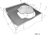
Figure 4 is a schematic representation of an image of a portion of a package superimposed on the respective portion of the package; with parts removed for clarity. - Number 1 indicates as a whole a packaging plant for producing
packages 2 filled with a pourable product, in particular a pourable food product, such as (pasteurized) milk, fruit juice, wine, tomato sauce, salt, sugar, emulsions, yoghurt, milk drinks etc. - Packaging plant 1 may be configured to produce
packages 2 filled with the pourable product. - In more detail, packaging plant 1 may be configured to produce
packages 2 from a packaging material having a multilayer configuration. - In further detail, the packaging material may comprise at least one layer of fibrous material, such as e.g. a paper or cardboard, and at least two layers of heat-seal plastic material, e.g. polyethylene, interposing the layer of fibrous material in between one another. One of these two layers of heat-seal plastic material may define the inner face of
package 2 contacting the pourable product. - Moreover, the packaging material may also comprise a layer of gas- and light-barrier material, e.g. aluminum foil or ethylene vinyl alcohol (EVOH) film, in particular being arranged between one of the layers of the heat-seal plastic material and the layer of fibrous material. Preferentially, the packaging material may also comprise a further layer of heat-seal plastic material being interposed between the layer of gas- and light-barrier material and the layer of fibrous material.
- In further detail, the packaging material may be provided in the form of a web 3.
- With particular reference to
Figures 1 to 4 , eachpackage 2 may comprise a respectivemain body 4 formed from the multilayer packaging material and anopening device 5 arranged about a pour opening (not shown) of the respectivemain body 4. - In more detail,
main body 4 may extend along a longitudinal axis A, a first transversal axis B perpendicular to longitudinal axis A and a second transversal axis C perpendicular to first transversal axis B and longitudinal axis A. Preferentially, the size ofpackage 2 along longitudinal axis A may be larger than the size ofpackage 2 along first transversal axis B and second transversal axis C. - Preferentially,
main body 4 may be parallelepiped-shaped. - According to some preferred non-limiting embodiments,
main body 4 may comprise a first wall, preferentially being transversal, more preferentially perpendicular, to longitudinal axis A, from whichmain body 4 may extend along longitudinal axis A. More specifically, the first wall may define a support surface ofpackage 2, preferentiallymain body 4, which may be designed to be put in contact with a support, such as e.g. a shelf, when, in use, being e.g. exposed within a sales point or when being stored. - The first wall may define a bottom wall of
package 2, in particularmain body 4. - Preferentially,
main body 4 may also comprise aside wall 6 being (fixedly) connected to first wall and extending, along longitudinal axis A, from first wall. - Preferentially,
main body 4 may also comprise asecond wall 7 opposite to first wall and being (fixedly) connected toside wall 6. - Preferentially,
side wall 6 may be interposed between and integrally connected to the first wall andsecond wall 7. - Preferentially,
second wall 7 may define a top wall ofpackage 2. - According to the shown non-limiting embodiment, the first wall and
second wall 7 may be parallel with respect to one another. - According to some other possible embodiments not shown,
second wall 7 and the first wall may be inclined with respect to one another, more specificallysecond wall 7 may be inclined with respect to the first wall and/or longitudinal axis A. - According to some non-limiting embodiments,
second wall 7 may carry and/or comprise the designated pour opening and openingdevice 5 may be connected tosecond wall 7. - According to some possible embodiments, each pour opening may be covered by a separation membrane, the separation membrane being preferentially formed from portions of the multilayer packaging material.
- Each
opening device 5 may comprise acollar 8 protruding from the respectivemain body 4, preferentiallysecond wall 7, and being arranged about the respective pour opening. Preferentially, eachcollar 8 may comprise a respective outlet opening configured to allow for the outpouring of the pourable product. - Each
opening device 5 may also comprise acap 9 secured ontocollar 8, and more specifically may be configured to selectively open and close the respective outlet opening. - In more detail, each
collar 8 may include an outer projection and eachcap 9 may comprise an inner projection, configured to engage with the outer projection of therespective collar 8 for securingcap 9 oncollar 8. - By securing
cap 9 ontocollar 8 one arrangedcap 9 ontomain body 4. - In further detail, each
cap 9 may be controllable between a respective closing position at whichcap 9 closes the outlet opening (for impeding the outflow of the pourable product) and an opening position at which cap 9 frees the outlet opening (for allowing the outflow of the pourable product). Preferentially, eachcap 9 is secured to therespective package 2 and is in the closing position when being delivered to an end user. - Advantageously, each
cap 9 may be (repeatably) moveable between the respective closing position and the respective opening position. - Moreover, each
cap 9 may comprise aprincipal wall 10 configured to cover the outlet opening, in particular withcap 9 being in the closing position. - Advantageously,
principal wall 10 may have a (substantially) circular shape. - Each
cap 9 may also comprise anopening lip 11 protruding fromprincipal wall 10 and being configured to facilitate control ofcap 9 from the closing position to the opening position. - In
further detail cap 9, more specificallyprincipal wall 10, may comprise aperipheral portion 12. More specifically,peripheral portion 12 may be defined as an annular portion ofcap 9, more specificallyprincipal wall 10. In particular,peripheral portion 12 can be described by an outer circle and an inner circle. The outer circle may correspond to the outer edge ofcap 9, more specificallyprincipal wall 12, and may have a first diameter. The inner circle may be described by a second diameter being equal to or larger than 75%, more specifically 85%, even more specifically 90%, of the first diameter. The second diameter is of course smaller than the first diameter. - Additionally, each
cap 9 may comprise alateral wall 13 protruding from the respectiveprincipal wall 10 and being configured to surround at least a portion of therespective collar 8, in particular withcap 9 being in the closing position; i.e. eachlateral wall 13 surrounds the respective portion ofcollar 8 aftercap 9 has been secured onto therespective collar 8. - According to some possible embodiments, each
opening device 5 may also comprise a respective coupling element connected to and protruding from the respective separation membrane. Preferentially, each coupling element may be also connected to, preferentially sealed to, therespective cap 9. In particular, during a first-time control of therespective cap 9 into the respective opening position, the coupling element follows movement of therespective cap 9 leading to a detachment of the respective separation membrane from the respectivemain body 4. - More specifically, each coupling element may be surrounded by the
respective collar 8. Even more specifically, each coupling element may comprise a portion protruding out ofcollar 8 and this portion may be sealed to cap 9. - According to some preferred non-limiting embodiments, each
opening device 5 may also comprise a base frame carrying therespective collar 8 and being connected to, more specifically molded onto or bonded or adhesively bonded or glued to, the respectivemain body 4. - Advantageously, each
collar 8 may be integral to the respective base frame and/or may extend from the respective base frame. - In further detail, each
collar 8 may extend along a respective central axis. - Moreover, each
collar 8 may have an annular shape. More specifically, eachcollar 8 may have a circular shape. - According to some preferred non-limiting embodiments, each
collar 8 may be molded to the respectivemain body 4, more specifically the respectivesecond wall 7. For example, eachcollar 8 may be molded to web of packaging material 3 prior to forming and fillingpackages 2, more specificallymain body 4. - More specifically, each
collar 8 may be molded onto the respectivemain body 4 together with the respective base frame. Even more specifically, eachcollar 8 may be molded onto web of packaging material 3 together with the respective base frame prior to forming and fillingpackages 2, preferentiallymain body 4. - Additionally, also each coupling element may be molded to the respective
main body 4, more specifically to web of packaging material 3 prior of forming and fillingpackages 2, preferentiallymain body 4. - With particular reference to
Figure 1 , packaging plant 1 may comprise: - a
package filling apparatus 14 configured to form and fillpackages 2, in particular configured to formpackages 2 from the multilayer packaging material and to fillpackages 2 with the pourable product; and - at least one capping
machine 15 configured to at least apply onerespective cap 9 to eachmain body 4, more specifically onto therespective collar 8 protruding frommain body 4. - In more detail, capping
machine 15 may be arranged downstream frompackage filling apparatus 14 and may be configured to receive formed and filledpackages 2 frompackage filling apparatus 14. - Please note that for reasons of simplicity, in the present description, when discussing operation of capping
machine 15, we do not use different terms to indicatepackages 2 which still need to receive therespective caps 9 and which have therespective caps 9. We consider that such differences are directly understandable from the description. - With particular reference to
Figure 1 , cappingmachine 15 comprises: - a conveying device configured to advance
packages 2 along and advancement path; and - a cap application device configured to apply one
respective cap 9 onto eachcollar 8. - In further detail, the cap application device may be configured to apply
caps 9 onto therespective collars 8, but after application these are not yet fully secured onto therespective collars 8. - In more detail, in use, after operation of the cap application device each
cap 9 may be only partially coupled to therespective collar 8. - Therefore, more specifically, capping
machine 15 may also comprise one or more cap securing devices configured to securecaps 9 onto therespective collars 8. E.g. each cap securing device may be configured to screw and/or pushcaps 9 onto therespective collars 8. - More specifically, each cap securing device ensures, in use, that each
cap 9 may be fully coupled to therespective collar 8. - In more detail, the cap securing devices may be arranged downstream from the cap application device along the advancement path.
- According to some possible embodiments, capping
machine 15 may comprise only one cap securing device. Alternatively, cappingmachine 15 may comprise more than one cap securing device configured to simultaneously securerespective caps 9 onto therespective collars 8. - According to some possible non-limiting embodiments, capping
machine 15 may also comprise one or more cap sealing devices configured to seal the respective coupling elements to therespective caps 9. - More specifically, the cap sealing devices may be arranged downstream from the cap securing device(s) along the advancement path.
- According to some possible embodiments, capping
machine 15 may comprise only one cap sealing device. Alternatively, cappingmachine 15 may comprise more than one cap sealing device configured to simultaneously seal the respective coupling elements to therespective caps 9. -
Figure 2A shows apackage 2 prior to the application of therespective cap 9 to the respectivemain body 2.Figures 2A and 2B illustrate the two cases, which may occur during the application ofcaps 9; i.e. therespective cap 9 is either correctly applied to the respectivemain body 4, in particular by having been correctly applied and secured to the respective collar 8 (seeFigure 2B ) or therespective cap 9 is incorrectly applied to the respectivemain body 4, in particular by not having been correctly applied and secured to the respective collar 8 (seeFigure 2C ). - In order to control on whether
caps 9 are correctly applied onto the respectivemain bodies 4, in particular by having been correctly applied and secured to therespective collars 8, cappingmachine 15 comprises aninspection apparatus 20 for inspectingcaps 9 applied to the respectivemain bodies 4, in particular by inspectingcaps 9 as applied and secured onto therespective collars 8. - In particular,
inspection apparatus 20 may be configured to determine an orientation of eachcap 9 with respect to the respectivemain body 4, more specifically the respectivesecond wall 7. Moreover, the orientation of eachcap 9 allows to selectively determine a correct or incorrect application of eachcap 9. - In more detail,
inspection apparatus 20 may be arranged downstream from the cap application device and/or the cap securing device(s) along the advancement path. - More specifically,
inspection apparatus 20 may also be arranged downstream from the cap sealing device(s) along the advancement path. - In more detail,
inspection apparatus 20 comprises an imaging device configured to acquire at least oneimage 21 perpackage 2 of aninspection portion 22 ofpackage 2. - Advantageously, the imaging device may be configured to acquire exactly one
image 21 perpackage 2. - More specifically, the imaging device may be, during the acquisition, be arranged above the
respective package 2. - In more detail, each
image 21 is acquired in a direction (substantially) perpendicular to the respectivesecond wall 7 and/or the respectiveprincipal wall 10. - According to some possible embodiments, the imaging device comprises and/or is a 3D camera, specifically a digital video camera, more specifically a 3D digital video camera, configured to acquire
images 21. Preferentially, the imaging device is configured acquire a three-dimensional image 21 of thepackage 2. - E.g. the imaging device may be configured to execute a 3D profiling (laser triangulation).
- As shown in
Figures 3 and4 ,inspection portion 22 has a main wall ofmain body 4 andcap 9. In particular, the respectivesecond wall 7 defines the main wall (thus, in the following we refer tosecond wall 7 instead of main wall). - In more detail (see
Figure 4 ), each acquired image may be a pixel image. Thereby a first set 23 of pixels represents and/or corresponds tosecond wall 7 and asecond set 24 of pixels represents and/or corresponds to cap 9. - Moreover, each first set 23 of pixels and the respective second set 24 of pixels are spaced apart from one another along a first direction more specifically being (substantially) perpendicular to,
second wall 7. -
Inspection apparatus 20 also comprises an analyzing unit configured to analysis eachimage 21. Preferentially, the analyzing unit is configured to determine the orientation of eachcap 9 with respect to the respectivemain body 4, more specifically the respectivesecond wall 7. Additionally, the analyzing unit may be configured to selectively determine a correct or incorrect application of eachcap 9 based on the determined orientation. - More specifically, in case that the determined orientation lies within a given range, the analyzing unit may classify the
respective cap 9 as correctly applied and if the determined orientation lies out from the given range, the analyzing unit may classify therespective cap 9 to be incorrectly applied. - In more detail, analyzing unit may be connected to the imaging device so as to receive the images from the imaging device for analysis.
- The analyzing unit may be configured to analyze each
image 21 and to determine respective distances d between two ormore reference points 25, in the specific case shown four, ofcap 9, andsecond wall 7 as represented in therespective image 21. More specifically,reference points 25 may lies on anouter surface 26 ofcap 9. - In more detail, the respective
outer surface 26 may face away from the respective pouring outlet of therespective collar 8 with therespective cap 9 being arranged on therespective collar 8 and with therespective cap 9 being in the respective closing position. - Additionally, the analyzing unit is configured to determine the orientation (and therewith the correct application) of the
respective caps 9 based on the two or more distances d. - It should be noted that
reference points 25 are different from one another. - By relying on at least three, more specifically at least four
reference points 25 and therefore at least three distances d, more specifically at least four distances, it is possible to increase the preciseness of the determination of the orientation ofcaps 9. - According to the specific embodiment shown, in case of an ideally oriented and/or correctly applied
cap 9, the respective distances d should be approximately equal. - Accordingly, in case that distances d determined from one
respective image 21 are approximately equal with one another (i.e. distances d fall into a tolerance regime), therespective cap 9 has a respective orientation, which corresponds to a correctly appliedcap 9. - In case that distances d determined from one
respective image 21 differ (i.e. distances d fall out of a tolerance regime), therespective cap 9 has a respective orientation, which corresponds to an incorrectly appliedcap 9. - In further detail, the analyzing unit may be configured to determine a correctly applied
cap 9 if the respective distances d lies within a pre-determined range and/or to determine an incorrectly appliedcap 9 if at least one of the respective distances d lies outside of a pre-determined range. - In further detail and with particular reference to
Figures 3 and4 , analyzing unit may be configured to setreference points 25 to be angularly displaced from one another about a center axis E of therespective cap 9. - Additionally, center axis E may be coaxial to a central axis of the
respective collar 8, in particular when therespective cap 9 is correctly applied onto therespective collar 8. - According to some possible embodiments, analyzing unit may be configured to set
reference points 25 to be equally spaced from one another about the respective center axis E. - In the example shown,
reference points 25 are angularly spaced apart from one another about the respective center axis E at an angle of 90°. - Advantageously,
reference points 25 may be associated (i.e. arranged on) to the respectiveprincipal wall 10 and/or the respectiveperipheral portion 12. Preferentially,reference points 25 are positioned between said second (inner) diameter and said first (outer) diameter corresponding to the outer edge ofcap 9. - In particular, one or more or all
reference points 25 may be associated to (i.e. arranged on) an outer edge ofprincipal wall 10. - According to some possible embodiments, the analyzing unit may be configured such that all
reference points 25 may lie on at least an imaginary circle. - In more detail, the analyzing unit may be configured to extrapolate and/or estimate a respective first plane H1 from each
image 21. The respective first plane H1 describes (i.e. is representative of) the respectivesecond wall 7. - More specifically, the analyzing unit may be configured to extrapolate and/or estimate each first plane H1 from the respective first set 23 of pixels. Even more specifically, the analyzing unit may be configured to execute a fitting operation on each first set 23 of pixels so as to extrapolate and/or estimate the respective first plane H1.
- Advantageously, the respective distance d between each reference points 25 and the respective
second wall 7 may be determined as the distance between therespective reference point 25 and the respective first plane H1. - In particular, the analyzing unit may be configured to determine each distance d from the
respective reference point 25 to the respective first plane H1 along a direction perpendicular to the respective first plane H1. - According to some possible embodiments, the analyzing unit may be configured to extrapolate and/or estimate a second plane H2 from each
image 21. The respective second plane H2 is associated to therespective cap 9, more specifically at least the respectiveprincipal wall 10 and/or therespective opening lip 11. - More specifically, each second plane H2 may describe the respective
outer surface 26. - According to some possible embodiments,
reference points 25 may lie on the respective second plane H2. In particular, the analyzing unit identifies thereference points 25 among points of the second plane H2. - More specifically, the analyzing unit may be configured to extrapolate and/or estimate each second plane H2 from the respective second set 24 of pixels. Even more specifically, the analyzing unit may be configured to execute a fitting operation on each second set 24 of pixels so as to extrapolate and/or estimate the respective second plane H2.
- According to such embodiments, each distance d may be the distance between the respective first plane H1 and the respective second plane H2 at the respective locally restricted
reference point 25. - With particular reference to
Figure 1 ,package filling apparatus 14 may be configured to producepackages 2 and to fillpackages 2 with the pourable product. - In more detail,
package filling apparatus 14 may be configured to producepackages 2 by forming atube 50 from web 3, longitudinally sealingtube 50, fillingtube 50 with the pourable product and to transversally seal and cuttube 50. - In use, packaging plant 1 produces
packages 2 filled with the pourable product. - Operation of packaging plant 1 comprises at least the steps of:
- forming and filling
packages 2 with the pourable product, in particular executed by ofpackage filling apparatus 14; and - securing
caps 9 oncollars 8, in particular executed by cappingmachine 15. - Even more particular, during the step of forming and filling,
tube 50 is formed from advancing web 3, is longitudinally sealed, filled with the pourable product and transversally sealed and cut. - According to some preferred embodiments, operation of packaging plant 1 may also comprise a step of feeding, during which packages 2 are fed, in particular from
package filling apparatus 7, to cappingmachine 15. - In more detail, during the step of securing, the following sub-steps are executed:
- advancing
main bodies 4 along the advancement path; and - applying
caps 9 ontomain bodies 4; - In more detail, during the sub-step of applying, caps 9 are applied onto the
respective collars 8, in particular by means of the cap application device, so as to applycaps 9 ontomain bodies 4. - Additionally, during the step of securing, also the sub-step(s) of:
- securing
caps 9 oncollars 8 by means of a cap securing device; and/or - sealing the connection elements to
caps 9; - Additionally, after the application of
caps 9, caps 9 are inspected according to the following method (in other words, operation of packaging plant 1 also comprises a step of inspecting, during which caps 9 are inspected) . The method is executed for each one ofcaps 9. - The method comprises the steps of:
- acquiring, during which at least one
image 21 perpackage 2 is acquired, in particular by the inspection device, of therespective inspection portion 22; and - analyzing, during which each
image 21 is analyzed to determine the orientation ofcap 9 with respect to the respectivemain body 4, more specifically with respect to the respectivesecond wall 7. - In more detail, during the step of analyzing, from each
image 21, the respective distances d between therespective reference points 25 of therespective cap 9 and the respectivesecond wall 7 are determined and the orientation of therespective cap 9 is obtained based on the respective distances d. - In particular, the step of analyzing is executed by the analyzing unit.
- Moreover, a step of transferring may be executed, during which
image 21 is transferred from the imaging device to the analyzing unit. - According to some possible embodiments, during the step of analyzing, the respective first plane H1 may be extrapolated and/or estimated from the
respective image 21 and the respective distances (d) between therespective reference points 25 and the respectivesecond wall 7 are determined as the distance between therespective reference points 25 and the respective first plane H1. - More specifically, during the step of analyzing, the respective first plane H1 is extrapolated and/or estimated from the respective first set 23 of pixels. In particular, the respective first plane H1 is obtained by a fitting operation of the respective first set 23 of pixels.
- According to some possible embodiments, during the step of analyzing, the respective second plane H2 may be extrapolated and/or estimated from each
image 21. - More specifically, during the step of analyzing, the respective second plane H2 may be extrapolated and/or estimated from the respective second set 24 of pixels. In particular, the respective second plane H2 is obtained by a fitting operation of the respective second set 24 of pixels.
- The advantages of
inspection apparatus 20 and the method according to the present invention will be clear from the foregoing description. - In particular,
inspection apparatus 20 and the method allow to precisely determine a correct or incorrect application ofcaps 9. This again reduces the risk ofpackage 2 being delivered to end consumers, which may be difficult to be opened. - Clearly, changes may be made to
inspection apparatus 20 and/or cappingmachine 15 and/or packaging plant 1 and/or the method as described herein without, however, departing from the scope of protection as defined in the accompanying claims.
Claims (15)
- Inspection apparatus (20) for inspecting caps (9) applied to respective main bodies (4) of respective packages (2) ;wherein the inspection apparatus (20) comprises:- an imaging device configured to acquire at least one image (21) per package (2) of an inspection portion (22) of the package (2), wherein the inspection portion (22) includes: a main wall (7) of the main body (4), and the cap (9); and- an analyzing unit configured to analyze each image (21) and to determine an orientation of the cap (9) with respect to the main body (4);wherein the analyzing unit is configured to determine from each image (21) respective distances (d) between two or more reference points (25) of the cap (9), and the main wall (7), the reference points (25) being different from one another,;wherein the analyzing unit is also configured to determine the orientation of the respective cap (9) with respect to the main body (4) based on the two or more distances (d).
- Inspection apparatus according to claim 1, wherein the analyzing unit is configured such that the two or more reference points (25) are angularly displaced from one another and/or are equally spaced from one another about a center axis (E) of the cap (9).
- Inspection apparatus according to any one of the preceding claims, wherein the analyzing unit is configured such that the reference points (25) are positioned on a peripheral portion (12) of the cap (9).
- Inspection apparatus according to any one of the preceding claims, wherein the analyzing unit is configured to associate the reference points (25) to an outer surface (26) of the cap (9) .
- Inspection apparatus according to any one of the preceding claims, wherein the analyzing unit is configured to extrapolate and/or estimate a respective first plane (H1) from each image (21), the first plane (H1) describing the respective main wall (7);
wherein the analyzing unit is configured to determine the respective distances (d) between the reference points (25) and the main wall (7) as the distance between the reference points (25) and the first plane (H1). - Inspection apparatus according to any one of the preceding claims, wherein the analyzing unit is configured to extrapolate and/or estimate a second plane (H2) from each image (21);wherein the respective second plane (H2) is associated to the respective cap (9);wherein the two or more reference points (25) lie on the second plane (H2).
- Inspection apparatus according to any one of the preceding claims, wherein the analyzing unit is configured to determine from each image (21) the respective distances (d) between at least three reference points (25) of the cap (9) .
- Inspection apparatus according to any one of the preceding claims, wherein the analyzing unit is configured to determine a correctly applied cap (9) if the respective distances (d) lie within a pre-determined range and/or if the respective distances (d) substantially equal one another and/or to determine an incorrectly applied cap (9) if at least one of the respective distances (d) lies outside of a pre-determined range.
- Inspection apparatus according to any one of the preceding claims, wherein the inspection device comprises a 3D camera.
- Capping machine (15) for applying caps (9) onto main bodies (4) of packages (2) comprising:- a cap application apparatus configured to apply caps onto the main bodies (4) of the packages (2); and- an inspection apparatus (20) according to any one of the preceding claims configured to inspect the orientation of each respective cap (9) with respect to the respective main body (4).
- Packaging plant (1) for producing packages (2) having each a main body (4) and a cap (9) applied onto the main body (4) and being filled with a pourable product comprising:- a package filling apparatus (14) for forming and filling the main bodies (4) with the pourable product; and- at least one capping machine (15) according to claim 10.
- Method of inspecting caps (9) applied to respective main bodies (4) of respective packages (2);the method comprises the steps of:- acquiring, during which at least one image (21) per package (2) is acquired of an inspection portion (22) of the package (2), wherein the inspection portion (22) includes: a main wall (7) of the main body (4), and the cap (9); and- analyzing, during which each image (21) is analyzed to determine an orientation of the cap (9) with respect to the main body (4);wherein during the step of analyzing from each image (21) respective distances (d) between two or more reference points (25) of the cap (9), the reference points (25) being different from one another, and the main wall (7) are determined;wherein during the step of analyzing, the orientation of the respective cap (9) is obtained based on the two or more distances (d).
- Method according to claim 12, wherein the two or more reference points (25) are angularly displaced from one another and/or are equally spaced from one another about a center axis (E) of the cap (9).
- Method according to claim 12 or 13, wherein during the step of analyzing a respective first plane (H1) is extrapolated and/or estimated from each image (21), the first plane (H1) describing the respective main wall (7); wherein during the step of analyzing the respective distances (d) between the reference points (25) and the main wall (7) are determined as the distance between the reference points (25) and the first plane (H1); and/or
wherein during the step of analyzing a second plane (H2) is extrapolated and/or estimated from each image (21); wherein the respective second plane (H2) is associated to the respective cap (9); wherein the two or more reference points (25) lie on the second plane (H2). - Method of applying caps (9) onto main bodies (4) of packages (2) comprising the steps of:- advancing main bodies (4) along an advancement path;- applying caps (9) onto the main bodies (4); and- inspecting the caps (9) by executing a method according to any one of claims 12 to 14.
Applications Claiming Priority (1)
| Application Number | Priority Date | Filing Date | Title |
|---|---|---|---|
| IT102023000019134A IT202300019134A1 (en) | 2023-09-18 | 2023-09-18 | INSPECTION APPARATUS FOR A CAPPING MACHINE, CAPPING MACHINE HAVING AN INSPECTION APPARATUS, PACKAGING PLANT, METHOD OF INSPECTING CAPS AND METHOD OF CAPPING |
Publications (1)
| Publication Number | Publication Date |
|---|---|
| EP4524086A1 true EP4524086A1 (en) | 2025-03-19 |
Family
ID=88839575
Family Applications (1)
| Application Number | Title | Priority Date | Filing Date |
|---|---|---|---|
| EP24192235.0A Pending EP4524086A1 (en) | 2023-09-18 | 2024-08-01 | Inspection apparatus for a capping machine, respective capping machine and packaging plant |
Country Status (4)
| Country | Link |
|---|---|
| EP (1) | EP4524086A1 (en) |
| CN (1) | CN121866222A (en) |
| IT (1) | IT202300019134A1 (en) |
| WO (1) | WO2025061360A1 (en) |
Citations (2)
| Publication number | Priority date | Publication date | Assignee | Title |
|---|---|---|---|---|
| US20200198953A1 (en) * | 2018-12-19 | 2020-06-25 | Silgan White Cap LLC | Dual Laser Closure Scan and Method of Using the Same |
| WO2022248145A1 (en) * | 2021-05-28 | 2022-12-01 | Tetra Laval Holdings & Finance S.A. | A method for quality assessment of a food package and a packaging system |
-
2023
- 2023-09-18 IT IT102023000019134A patent/IT202300019134A1/en unknown
-
2024
- 2024-08-01 WO PCT/EP2024/071789 patent/WO2025061360A1/en active Pending
- 2024-08-01 EP EP24192235.0A patent/EP4524086A1/en active Pending
- 2024-08-01 CN CN202480059501.9A patent/CN121866222A/en active Pending
Patent Citations (2)
| Publication number | Priority date | Publication date | Assignee | Title |
|---|---|---|---|---|
| US20200198953A1 (en) * | 2018-12-19 | 2020-06-25 | Silgan White Cap LLC | Dual Laser Closure Scan and Method of Using the Same |
| WO2022248145A1 (en) * | 2021-05-28 | 2022-12-01 | Tetra Laval Holdings & Finance S.A. | A method for quality assessment of a food package and a packaging system |
Also Published As
| Publication number | Publication date |
|---|---|
| WO2025061360A1 (en) | 2025-03-27 |
| IT202300019134A1 (en) | 2025-03-18 |
| CN121866222A (en) | 2026-04-14 |
Similar Documents
| Publication | Publication Date | Title |
|---|---|---|
| US10543946B2 (en) | Sheet of packaging material for producing a container and method for producing containers | |
| CN114981175B (en) | Cap assembly for packaging, cap and spout set for packaging and package having cap and spout set | |
| DK3153415T3 (en) | DEVICE TO CLOSE A CONTAINER | |
| US10293972B2 (en) | Opening device and apparatus for moulding an opening device on a sheet packaging material | |
| US10967996B2 (en) | Method of, and an applying head for, applying a lid onto a container | |
| CN114981177A (en) | Lid and spout assembly for a package and package having a lid and spout assembly | |
| US5924267A (en) | Process and a device for closing filled folded-carton packages | |
| JP2024535253A (en) | Opening device for a package, mold for molding the opening device for a package, and package having the opening device | |
| CN107921715B (en) | Welding head | |
| WO2025061360A1 (en) | Inspection apparatus for a capping machine, respective capping machine and packaging plant | |
| EP4524087A1 (en) | Inspection apparatus for a capping machine, respective capping machine and packaging plant | |
| EP4091953B1 (en) | Composite packaging material sheet, method for forming a composite packaging material sheet, composite package and method for forming a composite package | |
| JP2024535243A (en) | Opening device for a package, mold for molding the opening device for a package, and package having the opening device | |
| EP4538219B1 (en) | Inspection apparatus for a capping apparatus, capping apparatus having an inspection apparatus, packaging machine, method of inspecting caps and method of applying caps | |
| US20190135470A1 (en) | An assembly for producing sealed packaging units | |
| EP4491524B1 (en) | Cap application device for a capping apparatus, capping apparatus for a packaging machine and packaging machine having a capping apparatus | |
| EP3647221A1 (en) | Cap angular orientation | |
| EP4464607A1 (en) | Cap application device for a capping apparatus, capping apparatus for a packaging machine and packaging machine having a capping apparatus | |
| EP4733035A1 (en) | Method and system for alignment of an injection molding module in relation to a web of packaging material | |
| EP4575472A1 (en) | Inspection system for a capping machine and method for inspecting closure structures pre-applied on packages containing a pourable product | |
| EP4455025A1 (en) | Capping apparatus for a packaging machine and packaging machine having a capping apparatus | |
| JP2026516354A (en) | Cap mounting device for cap mounting device, cap mounting device for packaging machine, and packaging machine equipped with cap mounting device | |
| JP2025506644A (en) | Lid assembly for a package, lid spout group for a package, and package having a lid spout group |
Legal Events
| Date | Code | Title | Description |
|---|---|---|---|
| PUAI | Public reference made under article 153(3) epc to a published international application that has entered the european phase |
Free format text: ORIGINAL CODE: 0009012 |
|
| STAA | Information on the status of an ep patent application or granted ep patent |
Free format text: STATUS: THE APPLICATION HAS BEEN PUBLISHED |
|
| AK | Designated contracting states |
Kind code of ref document: A1 Designated state(s): AL AT BE BG CH CY CZ DE DK EE ES FI FR GB GR HR HU IE IS IT LI LT LU LV MC ME MK MT NL NO PL PT RO RS SE SI SK SM TR |
|
| STAA | Information on the status of an ep patent application or granted ep patent |
Free format text: STATUS: REQUEST FOR EXAMINATION WAS MADE |
|
| 17P | Request for examination filed |
Effective date: 20250919 |