EP4524071A1 - Feeder module for a converting machine - Google Patents
Feeder module for a converting machine Download PDFInfo
- Publication number
- EP4524071A1 EP4524071A1 EP23197323.1A EP23197323A EP4524071A1 EP 4524071 A1 EP4524071 A1 EP 4524071A1 EP 23197323 A EP23197323 A EP 23197323A EP 4524071 A1 EP4524071 A1 EP 4524071A1
- Authority
- EP
- European Patent Office
- Prior art keywords
- blanks
- chain
- dented
- module according
- feeder module
- Prior art date
- Legal status (The legal status is an assumption and is not a legal conclusion. Google has not performed a legal analysis and makes no representation as to the accuracy of the status listed.)
- Granted
Links
Images



Classifications
-
- B—PERFORMING OPERATIONS; TRANSPORTING
- B65—CONVEYING; PACKING; STORING; HANDLING THIN OR FILAMENTARY MATERIAL
- B65H—HANDLING THIN OR FILAMENTARY MATERIAL, e.g. SHEETS, WEBS, CABLES
- B65H3/00—Separating articles from piles
- B65H3/46—Supplementary devices or measures to assist separation or prevent double feed
- B65H3/56—Elements, e.g. scrapers, fingers, needles, brushes, acting on separated article or on edge of the pile
-
- B—PERFORMING OPERATIONS; TRANSPORTING
- B65—CONVEYING; PACKING; STORING; HANDLING THIN OR FILAMENTARY MATERIAL
- B65H—HANDLING THIN OR FILAMENTARY MATERIAL, e.g. SHEETS, WEBS, CABLES
- B65H3/00—Separating articles from piles
- B65H3/02—Separating articles from piles using friction forces between articles and separator
- B65H3/04—Endless-belt separators
- B65H3/042—Endless-belt separators separating from the bottom of the pile
-
- B—PERFORMING OPERATIONS; TRANSPORTING
- B65—CONVEYING; PACKING; STORING; HANDLING THIN OR FILAMENTARY MATERIAL
- B65H—HANDLING THIN OR FILAMENTARY MATERIAL, e.g. SHEETS, WEBS, CABLES
- B65H3/00—Separating articles from piles
- B65H3/08—Separating articles from piles using pneumatic force
- B65H3/12—Suction bands, belts, or tables moving relatively to the pile
- B65H3/124—Suction bands or belts
- B65H3/126—Suction bands or belts separating from the bottom of pile
-
- B—PERFORMING OPERATIONS; TRANSPORTING
- B65—CONVEYING; PACKING; STORING; HANDLING THIN OR FILAMENTARY MATERIAL
- B65H—HANDLING THIN OR FILAMENTARY MATERIAL, e.g. SHEETS, WEBS, CABLES
- B65H2404/00—Parts for transporting or guiding the handled material
- B65H2404/30—Chains
- B65H2404/31—Chains with auxiliary handling means
- B65H2404/311—Blades, lugs, plates, paddles, fingers
-
- B—PERFORMING OPERATIONS; TRANSPORTING
- B65—CONVEYING; PACKING; STORING; HANDLING THIN OR FILAMENTARY MATERIAL
- B65H—HANDLING THIN OR FILAMENTARY MATERIAL, e.g. SHEETS, WEBS, CABLES
- B65H2404/00—Parts for transporting or guiding the handled material
- B65H2404/60—Other elements in face contact with handled material
- B65H2404/62—Transversely-extending bars or tubes
- B65H2404/623—Transversely-extending bars or tubes gate arrangement
-
- B—PERFORMING OPERATIONS; TRANSPORTING
- B65—CONVEYING; PACKING; STORING; HANDLING THIN OR FILAMENTARY MATERIAL
- B65H—HANDLING THIN OR FILAMENTARY MATERIAL, e.g. SHEETS, WEBS, CABLES
- B65H2701/00—Handled material; Storage means
- B65H2701/10—Handled articles or webs
- B65H2701/17—Nature of material
- B65H2701/176—Cardboard
Definitions
- the present invention relates to a converting machine for producing packaging items such as paper and cardboard boxes.
- the invention relates to a feeder module configured to discharge sheets or blanks one by one into the converting machine.
- Converting machines such as folder-gluers are used in the production of packaging items such as paperboard and cardboard boxes. These machines are configured to receive sheets or cut-to-shaped blanks and then fold and glue them to form folding boxes or other similar packaging containers.
- a feeder module is arranged at an inlet of the converting machine.
- the feeder module comprises a loading surface configured to receive a stack of sheets or cut-to-shaped blanks.
- the feeder module further comprises a gauge and a discharge conveyor which is configured to drive the lowermost positioned blank in the stack through a clearance defined between the gauge and the discharge conveyor.
- a feeder module for a converting machine.
- the feeder module comprises an upper feeder assembly and a lower feeder assembly, wherein the lower feeder assembly comprises a loading surface configured to receive a stack of blanks, and a discharge conveyor configured to grasp a lowermost positioned blank in the stack and convey it forward in a direction of transportation.
- the upper feeder assembly comprises at least one gauge configured to abut against a front side of the stack, and wherein a tip of the at least one gauge is arranged at a distance from the discharge conveyor, said distance defining a clearance for the lowermost positioned blank.
- the upper feeder assembly further comprises a dented chain provided with a plurality of teeth, and wherein the teeth are configured to enter into the stack in-between the blanks.
- the invention is based on a realization that the weight of the stack can be maintained constant if the weight of an upper part of the stack is supported by a protruding surface such as a tooth of a chain. In such a way, the friction may be maintained constant and calibrated to avoid scratching the blanks.
- blade may refer to both cut-to-shaped blanks and sheets.
- the sheets may have a rectangular or square shape.
- the teeth comprise an upper contact surface configured to abut against a bottom surface of the blanks. In such a way, the weight of blanks located in an upper portion of the stack above the teeth can be supported.
- the upper contact surface of the teeth is downwardly sloping in in the vertical direction.
- the teeth comprise an upper contact surface, a lower contact surface and a crest, said contact surfaces being defined from a trough to the crest, and wherein the upper contact surface is longer than the lower contact surface, whereby the upper contact surface is downwardly sloping in the vertical direction.
- the lower contact surface has an extension which coincides with the extension of the top surface of the blanks.
- the lower contact surface has a horizontal extension.
- the teeth comprise a lower contact surface configured to abut against a top surface of the blanks and to apply a downwardly directed force on the blanks.
- the dented chain is a loop comprising an exposed portion and a return portion, and wherein the dented chain is arranged such that only an exposed portion is in contact with the blanks.
- the gauge may be provided with an opening through which the exposed portion of the dented chain horizontally extends.
- the opening is located above an angled or rounded inlet portion of the gauge.
- the dented chain comprises an internal engagement surface, and wherein the internal engagement surface is in contact with a plurality of idle rollers and a motorized drive roller.
- At least one idle roller is configured as a diverting roller, and wherein the diverting roller is configured to position the dented chain such as to produce a horizontal projection in the exposed portion of the dented chain.
- the protruding portion horizontally projects through the opening in the gauge.
- a plurality of teeth is in contact with the blanks and wherein a lowermost positioned tooth in the exposed portion has a shorter horizontal extension than the upper teeth located in the exposed portion.
- the dented chain is made from a flexible material, such that it is forming a flexible loop.
- the material may comprise a polymer, Thermoplastic Polyurethane or rubber.
- the dented chain is made in one piece. In other words, the dented chain is deprived from mechanical connectors such as fasteners or links.
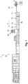
- figure 1 which illustrates a converting machine 1 in the form of a folder-gluer machine 1
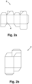
- figures 2a and 2b which illustrate a blank 2 to be processed in the converting machine 1 and a folding box 2'.
- the folder-gluer machine 1 is configured to receive a cut to shaped blank 2 as the one illustrated in figure 2b , and then fold and glue the blank 2 to form a folding box 2' or another folded and glued packaging container 2'.
- the converting machine 1 may be provided with a cutting and creasing module, whereby the converting machine 1 itself transforms a square or rectangular sheet into a cut-to-shaped blank.
- a cutting and creasing arrangement is described in document EP4157625 .
- the present folder-gluer machine 1 comprises a series of different workstations in the form of modules.
- the modules may include, from an inlet to an outlet of the converting machine 1, and in a direction of transportation T: a feeder module 10, an alignment module 11, a fold pre-breaking module 12, a gluing module 14 and a folding module 16.
- the folder-gluer machine 1 may further comprise a main user interface 15 and a quality control system 18.
- the lower distal end, i.e. the tip 32 of the gauge 30 may be provided with an angled portion 33.
- the angled portion 33 is arranged at an angle ⁇ in relation to the vertical axis V.
- the angle ⁇ is configured to define a downwardly sloping surface in the direction of transportation T.
Landscapes
- Engineering & Computer Science (AREA)
- Mechanical Engineering (AREA)
- Making Paper Articles (AREA)
Abstract
Description
- The present invention relates to a converting machine for producing packaging items such as paper and cardboard boxes. In particular, the invention relates to a feeder module configured to discharge sheets or blanks one by one into the converting machine.
- Converting machines such as folder-gluers are used in the production of packaging items such as paperboard and cardboard boxes. These machines are configured to receive sheets or cut-to-shaped blanks and then fold and glue them to form folding boxes or other similar packaging containers.
- A feeder module is arranged at an inlet of the converting machine. The feeder module comprises a loading surface configured to receive a stack of sheets or cut-to-shaped blanks. The feeder module further comprises a gauge and a discharge conveyor which is configured to drive the lowermost positioned blank in the stack through a clearance defined between the gauge and the discharge conveyor.
- In order to provide a correct discharge of sheets, there is a need to ensure that the blank is directed underneath the gauge. The blanks need to be pressed against the discharge conveyor to establish a sufficient contact; however, an excessive pressure may create deformation marks on the blanks. The height and thus the weight of the stack varies during production and this causes different contact pressures between the discharge conveyor and the blanks.
- It is an object of the present invention to ensure a correct adherence between the blanks and the feeder discharge conveyor.
- This object is solved by a feeder module according to
claim 1. - According to an aspect of the present invention, there is provided a feeder module for a converting machine. The feeder module comprises an upper feeder assembly and a lower feeder assembly, wherein the lower feeder assembly comprises a loading surface configured to receive a stack of blanks, and a discharge conveyor configured to grasp a lowermost positioned blank in the stack and convey it forward in a direction of transportation.
- The upper feeder assembly comprises at least one gauge configured to abut against a front side of the stack, and wherein a tip of the at least one gauge is arranged at a distance from the discharge conveyor, said distance defining a clearance for the lowermost positioned blank.
- The upper feeder assembly further comprises a dented chain provided with a plurality of teeth, and wherein the teeth are configured to enter into the stack in-between the blanks.
- The invention is based on a realization that the weight of the stack can be maintained constant if the weight of an upper part of the stack is supported by a protruding surface such as a tooth of a chain. In such a way, the friction may be maintained constant and calibrated to avoid scratching the blanks.
- Within the context of this application, the term "blank" may refer to both cut-to-shaped blanks and sheets. The sheets may have a rectangular or square shape.
- In an embodiment, the teeth comprise an upper contact surface configured to abut against a bottom surface of the blanks. In such a way, the weight of blanks located in an upper portion of the stack above the teeth can be supported.
- In an embodiment, the upper contact surface of the teeth is downwardly sloping in in the vertical direction.
- In an embodiment, the teeth comprise an upper contact surface, a lower contact surface and a crest, said contact surfaces being defined from a trough to the crest, and wherein the upper contact surface is longer than the lower contact surface, whereby the upper contact surface is downwardly sloping in the vertical direction.
- In an embodiment, the lower contact surface has an extension which coincides with the extension of the top surface of the blanks. Preferably, the lower contact surface has a horizontal extension.
- In an embodiment, the teeth comprise a lower contact surface configured to abut against a top surface of the blanks and to apply a downwardly directed force on the blanks.
- In an embodiment, the dented chain is a loop comprising an exposed portion and a return portion, and wherein the dented chain is arranged such that only an exposed portion is in contact with the blanks.
- The gauge may be provided with an opening through which the exposed portion of the dented chain horizontally extends.
- In an embodiment, the opening is located above an angled or rounded inlet portion of the gauge.
- In an embodiment, the dented chain comprises an internal engagement surface, and wherein the internal engagement surface is in contact with a plurality of idle rollers and a motorized drive roller.
- In an embodiment, at least one idle roller is configured as a diverting roller, and wherein the diverting roller is configured to position the dented chain such as to produce a horizontal projection in the exposed portion of the dented chain. Preferably, the protruding portion horizontally projects through the opening in the gauge.
- In an embodiment, a plurality of teeth is in contact with the blanks and wherein a lowermost positioned tooth in the exposed portion has a shorter horizontal extension than the upper teeth located in the exposed portion.
- In an embodiment, the dented chain is made from a flexible material, such that it is forming a flexible loop. The material may comprise a polymer, Thermoplastic Polyurethane or rubber. In a preferred embodiment, the dented chain is made in one piece. In other words, the dented chain is deprived from mechanical connectors such as fasteners or links.
- The invention will now be described with reference to the appended drawings, in which like features are denoted with the same reference numbers and in which:
-
Figure 1 is a schematic view of a converting machine in the configuration of a folder gluer; -
Figures 2a and 2b are top views of a blank and a folding box, respectively; -
Figure 3 is a schematic cross-sectional view of a feeder module according to an embodiment of the present invention; -
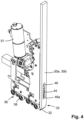
Figure 4 is a schematic perspective view of an upper feeder assembly according to an embodiment of the present invention; -
Figure 5 is schematic cross-sectional view of the upper feeder assembly and a stack of blanks; -
Figure 6a is a schematic cross-sectional view of a dented feeder chain according to an embodiment of the present invention; -
Figure 6b is detailed planar view of the tooth structure of the feeder chain offigure 6a ; -
Figure 6c is a detailed schematic perspective view of the feeder chain offigure 6a ; and -
Figures 7a and 7b are schematic perspective views of a feeder chain assembly from a first side and a second side, respectively. - Referring to the figures and in particular to
figure 1 which illustrates aconverting machine 1 in the form of a folder-gluer machine 1, andfigures 2a and 2b which illustrate a blank 2 to be processed in theconverting machine 1 and a folding box 2'. The folder-gluer machine 1 is configured to receive a cut to shaped blank 2 as the one illustrated infigure 2b , and then fold and glue the blank 2 to form a folding box 2' or another folded and glued packaging container 2'. Alternatively, theconverting machine 1 may be provided with a cutting and creasing module, whereby theconverting machine 1 itself transforms a square or rectangular sheet into a cut-to-shaped blank. Such a cutting and creasing arrangement is described in documentEP4157625 . - The present folder-
gluer machine 1 comprises a series of different workstations in the form of modules. The modules may include, from an inlet to an outlet of theconverting machine 1, and in a direction of transportation T: afeeder module 10, analignment module 11, a fold pre-breakingmodule 12, agluing module 14 and afolding module 16. The folder-gluer machine 1 may further comprise amain user interface 15 and aquality control system 18. - After the gluing and folding modules, a delivery module and
conditioning section 21 can be provided in order to count and separate a shingled stream of folding boxes 2' into separate batches. - The converting
machine 1 further comprises aconveyance system 19 comprising conveyors such as endless belts and rollers configured to transport theblanks 2 in a direction of transportation T. Theconverting machine 1 also comprises acentral control circuitry 20 configured to control the operation of theconverting machine 1. - The
feeder module 10 is configured to feed theblanks 2 one by one into theconverting machine 1. As illustrated infigure 3 , thefeeder module 10 comprises anupper feeder assembly 22 and alower feeder assembly 24, in-between which theblanks 2 are conveyed. - The
lower feeder assembly 24 comprises aloading surface 26 configured to receive a stack S ofblanks 2. Theloading surface 26 is provided with adischarge conveyor 28 configured to drive the lowermost positioned blank 2 in the stack S forward in the direction of transportation T. Thedischarge conveyor 28 preferably comprises a plurality of conveyor belts located side-by side and having their longitudinal extension coinciding with the direction of transportation T. Alternatively, in non-illustrated embodiments, thedischarge conveyor 28 may comprise drive elements in the shape of rollers or a single discharge conveyor. - In another, non-illustrated embodiment, the
loading surface 26 may further comprise a movable support surface comprising a plurality of elongated rods positioned in-between the plurality of conveyor belts. The movable support surface moves up and down such that the lowermost positioned blank 2 is in an alternating way brought into contact with and then distanced from the plurality of discharge conveyor belts. - The
upper feeder assembly 22 comprises afront stopper 30 in the form of at least onegauge 30, preferably the front stopper comprises twogauges discharge conveyor 28 is arranged at a distance C (seefigure 5 ) from avertical tip 32 of the at least onegauge blanks 2 in the vertical direction V. However, preferably the clearance C corresponds to the height of one blank 2 in in the vertical direction V. This clearance C ensures that only one blank 2 can be conveyed into the convertingmachine 1 at a time. Thegauge 30 may be slidably connected to achassis 34 of theupper feeder assembly 22 such that the vertical position of thetip 32 of the at least onegauge gauge - The
discharge conveyor 28 of thelower feeder assembly 24 may extend from theloading surface 26 to anoutlet 27 of the feeder module located downstream of thegauge 30. Thedischarge conveyor 28 is preferably accelerated and decelerated. In such a way, theblanks 2 are discharged in a stream and with a predefined spacing between each other. - As best seen in
figures 3 and5 , thegauge 30 is configured to abut against a front side of the stack S such as to restrict the horizontal movement of theupper blanks 2 in the stack. The upper portion of thegauge 30 is preferably provided with a vertical contact surface. In such a way, the upper portion of the stack S is maintained vertical. - The lower distal end, i.e. the
tip 32 of thegauge 30 may be provided with anangled portion 33. Theangled portion 33 is arranged at an angle α in relation to the vertical axis V. The angle α is configured to define a downwardly sloping surface in the direction of transportation T. - The
angled portion 33 enables the lowermost positioned blank 2 to be positioned further downstream in the direction of transportation T than the following blank 2, which is located on top of the lowermost positioned blank 2. Optionally, theangled portion 33 of thegauge 30 may also be rounded. The roundedportion 33 smoothly directs the front edges of theblanks 2 under thefront stopper 30. - As best seen in
figures 3 and4 , theupper feeder assembly 22 comprises anupper conveyor 36 configured to contact the upper side of theblanks 2. In such a way, the vertical position of theblanks 2 can be controlled. Theblanks 2 is received in-between theupper feeder assembly 22 and thelower feeder assembly 24 and are guided such that they are fed into the convertingmachine 1 in a straight manner without warps. - The
upper conveyor 36 may comprise a plurality ofrollers 38. Aspring 42 is acting on the rollers such as to bias therollers 38 against the blank 2. Anactuator 43 is operatively connected to therollers 38 and is configured to provide a variable force such that the pressure of therollers 38 can be modified. Theactuator 43 may be a pneumatic or hydraulic actuator. - The
upper feeder assembly 22 further comprises a dentedchain 44. The dentedchain 44 is a loop which comprises a plurality ofteeth 52. Theteeth 52 are configured to enter into the stack S in-between theblanks 2. - As best seen in
figure 6b , theteeth 52 are defined by acrest 55, anupper contact surface 54 and a lower contact surface 56. Each tooth is defined by acrest 55 located between twotroughs 57. - The dented
chain 44 may have a zig-zag shape. In a preferred embodiment, eachtooth 52 is non-symmetrical around a center line Lc through thecrest 55. The length L1 of theupper contact surface 54 is thus longer than the length L2 of the lower contact surface 56. The difference in length between L1 and L2 provides a skewed zig-zag shape. - The peak-to-peak distance P1 between the
crests 55 of directly adjacent teeth may be selected to correspond to the thickness of one blank 2. In this embodiment, there is onesheet 2 between eachtooth 52. - However, in a preferred embodiment, the peak-to-peak distance P1 between the
adjacent crests 55 is selected to exceed a maximum thickness of one blank 2. This is advantageous if the same dentedchain 44 is used for different types ofblanks 2 with variable thicknesses. Theteeth 52 of the chain may be introduced between each blank 2 in the stack. Alternatively, forthinner blanks 2, there areseveral blanks 2 present between theadjacent crests 55 of the dentedchain 44. In an advantageous embodiment, the peak-to-peak distance is between 5-15 mm, preferably about 11 mm. To increase the peak-to-peak distance P1, there may be aflat distance 53 between eachtrough 57 of theadjacent teeth 52. The distance between the troughs may be between 0 and 10 mm, preferably about 5 mm. - The
upper contact surface 54 of theteeth 52 is configured to contact a lower side of theblanks 2. As best seen infigures 5 ,7a and 7b , the dentedchain 44 has an exposed portion E which is in contact with theblanks 2. Preferably, the exposed portion E is located at the inlet portion I of thegauge 30. - In such a way, an upper part of the stack S1 which is located above the
teeth 52 in the exposed portion E is held by the dentedchain 44. The dentedchain 44 is configured to at least partly support the weight of the upper portion S1 of the stack S. - Additionally, the lower contact surface 56 of the
teeth 52 may be configured to grasp the front edges of theblanks 2 and guide them vertically downwards against thelower discharge conveyor 28. - The lower contact surface 56 of each
tooth 52 is preferably designed such that the lower contact surface 56 has an extension which coincides with the top surface of theblanks 2. This extension preferably coincides with the horizontal direction H. In such a way, theteeth 52 are provided with a flat surface which pushes against theblanks 2, and the risk of creating cut marks can be avoided. Preferably, the lower contact surface has a length of between 3 to 8 mm, preferably about 4 to 5 mm. - Optionally, the weight of the lower part of the stack S2 can be used to create a passive pressure and the pressure applied by the dented
chain 44 can be reduced while still obtaining a calibrated contact pressure between the lowermost positioned blank 2 and thedischarge conveyor 28. - The exposed portion E comprises a plurality of
teeth 52 which are simultaneously in contact with theblanks 2. Hence, the dentedchain 2 is in contact with a plurality ofblanks 2. In the illustrated embodiment, there are threeteeth 52 which project into the stack S. However, the number ofteeth 52 simultaneously engaging with theblanks 2 may be variable. - The at least one
gauge opening 46 through which the exposed portion E of the dentedchain 44 extends. Theopening 46 is preferably located above the inlet portion I of thegauge 30. Ideally, alower part 46a of theopening 46 is positioned at between 50 to 80 mm, preferably about 65 mm from thetip 33 thegauge 30. This allows a precise conveyance of theblanks 2 as they are positioned at the inlet path to the clearance C. Eachtooth 52 may have a lateral length of between 30 % to 50% of the width of the gauge. This lateral length may be between 10 mm and 20 mm. - Alternatively, in a non-illustrated embodiment, the
feeder chain 44 is located laterally of thegauge 30. The dentedchain 44 may be attached to a separate frame member. - The dented
chain 44 preferably also applies a force F to theblanks 2 such that the contact pressure between the lowermost positioned blank 2 and theloading surface 26 is sufficient for thelower discharge conveyor 28 to grasp and drive the lowermost positioned blank 2 forward in the direction of transportation. The force F may be in the range of between 20 to 180 Newton. - The dented
chain 44 may thus be configured to both apply a pressure on the lower part S2 of the stack, while supporting the weight of the upper portion S1 of the stack. - Due to the trajectory of the dented
chain 44, the lowermost positionedtooth 52 has a slope angle which is higher than the uppermost positionedtooth 52. Additionally, the lowermost positionedtooth 52 which is in contact with theblanks 2 has a smaller horizontal projection P than theteeth 52 in contact with theblanks 2 and located vertically above. The difference is horizontal projection P is achieved with the trajectory of the dentedchain 44. In such a way, theblanks 2 can disengage from theupper contact surface 54 of theteeth 52 and become positioned under the lower contact surface 56 of theteeth 52. - The dented
chain 44 has acontact side 47a and amotorized engagement side 47b. Themotorized engagement side 47b is located inside the loop defined by the dentedchain 44. Thecontact side 47a is in contact with theblanks 2 in the stack S. The dentedchain 44 has a direction of movement M such that theteeth 52 are moving vertically downwards in the exposed portion E. - As illustrated in
figures 7a and 7b , the dentedchain 44 is guided by a series of idle dented rollers 48 and amotorized drive roller 50. Themotorized drive roller 50 is driven in rotation by amotor 51. Themotor 51 may be configured to change the torque such that the pressing force F against theblanks 2 can be modified. In such a way, the force can be adapted to the material and geometry of the blanks 2.The idle rollers 48 and thedrive roller 50 are provided with gears configured to engage with a corresponding internal dented engagement surface 47 on the dentedchain 44. - At least one
idle roller 48a is configured as a divertingroller 48a. The divertingroller 48a is positioned outside of an axis A defined by a straight line extending through the center of the drive roller to the center of the distal lowermost positionedidle roller 48b. The divertingroller 48a changes direction of the dentedchain 44 such as to produce a protruding portion P which horizontally projects from the opening 31 in thegauge 30. - An axis B of the exposed portion E can be defined through a line extending through the rotational axis of the diverting
roller 48a and the lowermost positionedidle roller 48b. - The axis of the exposed portion E can be adjusted in the horizontal direction such as to vary the position of the length of the horizontal projection P. This allows an adaptation of the position of the
teeth 52 and adapt to material characteristics, such as paperboard or corrugated cardboard. - The dented
chain 44 can be produced in one piece without joints. In a preferred embodiment, the dentedchain 44 is made from a flexible material. The material may comprise a polymer such as Thermoplastic Polyurethane or rubber. - The manufacturing process of the dented chain may be by molding or sintering. However, it is advantageous to use an additive manufacturing process, i.e. a 3D printing process.
Claims (15)
- A feeder module (10) for a converting machine (1), the feeder module comprising an upper feeder assembly (22) and a lower feeder assembly (24), wherein the lower feeder assembly comprises a loading surface (26) configured to receive a stack (S) of blanks (2), and a discharge conveyor (28) configured to grasp a lowermost positioned blank (2) in the stack and convey it forward in a direction of transportation (T),
the upper feeder assembly comprising at least one gauge (30) configured to abut against a front side of the stack, and wherein a tip (32) of the at least one gauge is arranged at a distance from the discharge conveyor, said distance defining a clearance (C) for the blank, characterized in that the upper feeder assembly further comprises a dented chain (44) provided with a plurality of teeth (52), and wherein the teeth are configured to enter into the stack in-between the blanks. - The feeder module according to claim 1, wherein the teeth comprise an upper contact surface (54) configured to abut against a bottom surface of the blanks.
- The feeder module according to claim 1 or 2, wherein the teeth comprise a lower contact surface (56) configured to abut against a top surface of the blanks and to apply a downwardly directed force (F) on the blanks.
- The feeder module according to claim 2 or 3, wherein the upper contact surface of the teeth is downwardly sloping in the vertical direction (V).
- The feeder module according to claim 4, wherein the shape of the teeth comprises an upper contact surface (54), a lower contact surface (56) and a crest (55), said contact surfaces being defined from a trough (57) to the crest, and wherein the upper contact surface is longer than the lower contact surface.
- The feeder module according to the preceding claim, wherein the lower contact surface has an extension which coincides with the extension of the top surface of the blanks.
- The feeder module according to any one of the preceding claims, wherein the dented chain is a loop comprising an exposed portion (E) and a return portion, and wherein the dented chain is arranged such that only an exposed portion is in contact with the blanks.
- The feeder module according to the preceding claim, wherein the gauge is provided with an opening (46) through which an exposed portion of the dented chain horizontally extends.
- The feeder module according to the preceding claim, wherein the opening is located above an angled or rounded inlet portion (I) of the gauge.
- The feeder module according to the preceding claim, wherein the dented chain comprises an internal engagement surface, and wherein the engagement surface is in contact with a plurality of idle rollers (48a, 48b) and a motorized drive roller (50).
- The feeder module according to the preceding claim, wherein at least one idle roller (48b) is configured as a diverting roller (48b), and wherein the diverting roller is configured to position the dented chain such as to produce a horizontal projection (P) in the exposed portion of the dented chain.
- The feeder module according to the preceding claim, wherein the horizontal projection projects through the opening (46) in the gauge.
- The feeder module according to the preceding claim, wherein a plurality of teeth is in contact with the blanks and wherein a lowermost positioned tooth in the protruding portion has a shorter horizontal extension than the upper teeth located in the exposed portion (E).
- The feeder module according to any one of the preceding claims, wherein the dented chain is made from a flexible material, and wherein the dented chain is forming a flexible loop.
- The feeder module according to the preceding claim, wherein the flexible material comprises a polymer, Thermoplastic Polyurethane or rubber.
Priority Applications (4)
| Application Number | Priority Date | Filing Date | Title |
|---|---|---|---|
| PL23197323.1T PL4524071T3 (en) | 2023-09-14 | 2023-09-14 | Feeder module for a converting machine |
| EP23197323.1A EP4524071B1 (en) | 2023-09-14 | 2023-09-14 | Feeder module for a converting machine |
| PCT/EP2024/075446 WO2025056648A1 (en) | 2023-09-14 | 2024-09-12 | Feeder module for a converting machine |
| CN202480058835.4A CN121866217A (en) | 2023-09-14 | 2024-09-12 | Feeder module for converter |
Applications Claiming Priority (1)
| Application Number | Priority Date | Filing Date | Title |
|---|---|---|---|
| EP23197323.1A EP4524071B1 (en) | 2023-09-14 | 2023-09-14 | Feeder module for a converting machine |
Publications (3)
| Publication Number | Publication Date |
|---|---|
| EP4524071A1 true EP4524071A1 (en) | 2025-03-19 |
| EP4524071C0 EP4524071C0 (en) | 2026-02-18 |
| EP4524071B1 EP4524071B1 (en) | 2026-02-18 |
Family
ID=88068822
Family Applications (1)
| Application Number | Title | Priority Date | Filing Date |
|---|---|---|---|
| EP23197323.1A Active EP4524071B1 (en) | 2023-09-14 | 2023-09-14 | Feeder module for a converting machine |
Country Status (4)
| Country | Link |
|---|---|
| EP (1) | EP4524071B1 (en) |
| CN (1) | CN121866217A (en) |
| PL (1) | PL4524071T3 (en) |
| WO (1) | WO2025056648A1 (en) |
Citations (6)
| Publication number | Priority date | Publication date | Assignee | Title |
|---|---|---|---|---|
| US1948362A (en) * | 1932-07-05 | 1934-02-20 | Edwin G Staude | Blank feeder |
| CH378910A (en) * | 1960-06-10 | 1964-06-30 | Universal Corrugated Box Mach | Equipment for subsequently unloading the most underlying sheet from a stack of such sheets |
| JPS606863B2 (en) * | 1980-07-07 | 1985-02-21 | 田辺紙工機械製造株式会社 | Stacked paper pressing device in paper feed/discharge device |
| US10370208B2 (en) * | 2016-04-27 | 2019-08-06 | Indag Pouch Partners Gmbh | Batch feeder for piece goods made of flat material |
| EP4157625A1 (en) | 2020-05-26 | 2023-04-05 | Bobst Lyon | Creasing tool and method of creating crease lines |
| US11685619B1 (en) * | 2022-11-21 | 2023-06-27 | Masahiro TSUKASAKI | Paper feeding device and paper feeding method |
-
2023
- 2023-09-14 EP EP23197323.1A patent/EP4524071B1/en active Active
- 2023-09-14 PL PL23197323.1T patent/PL4524071T3/en unknown
-
2024
- 2024-09-12 CN CN202480058835.4A patent/CN121866217A/en active Pending
- 2024-09-12 WO PCT/EP2024/075446 patent/WO2025056648A1/en active Pending
Patent Citations (6)
| Publication number | Priority date | Publication date | Assignee | Title |
|---|---|---|---|---|
| US1948362A (en) * | 1932-07-05 | 1934-02-20 | Edwin G Staude | Blank feeder |
| CH378910A (en) * | 1960-06-10 | 1964-06-30 | Universal Corrugated Box Mach | Equipment for subsequently unloading the most underlying sheet from a stack of such sheets |
| JPS606863B2 (en) * | 1980-07-07 | 1985-02-21 | 田辺紙工機械製造株式会社 | Stacked paper pressing device in paper feed/discharge device |
| US10370208B2 (en) * | 2016-04-27 | 2019-08-06 | Indag Pouch Partners Gmbh | Batch feeder for piece goods made of flat material |
| EP4157625A1 (en) | 2020-05-26 | 2023-04-05 | Bobst Lyon | Creasing tool and method of creating crease lines |
| US11685619B1 (en) * | 2022-11-21 | 2023-06-27 | Masahiro TSUKASAKI | Paper feeding device and paper feeding method |
Also Published As
| Publication number | Publication date |
|---|---|
| WO2025056648A1 (en) | 2025-03-20 |
| PL4524071T3 (en) | 2026-04-27 |
| EP4524071C0 (en) | 2026-02-18 |
| CN121866217A (en) | 2026-04-14 |
| EP4524071B1 (en) | 2026-02-18 |
Similar Documents
| Publication | Publication Date | Title |
|---|---|---|
| EP4188859B1 (en) | Transfer module for a converting machine | |
| EP4524071B1 (en) | Feeder module for a converting machine | |
| US11667097B2 (en) | Method and system for processing blanks for forming constructs | |
| KR20260057659A (en) | Feeder module for converting machine | |
| EP4188854B1 (en) | Stacker module for a converting machine | |
| US20250051126A1 (en) | Separator device for a converting machine | |
| US12606393B2 (en) | Feeder with moving belt | |
| TWI847443B (en) | Adjustable conveyor system for a converting machine | |
| US20250122035A1 (en) | Feeder module | |
| CN119421782A (en) | Blank joining module | |
| IES59845B2 (en) | Manufacturing paperboard blanks |
Legal Events
| Date | Code | Title | Description |
|---|---|---|---|
| PUAI | Public reference made under article 153(3) epc to a published international application that has entered the european phase |
Free format text: ORIGINAL CODE: 0009012 |
|
| STAA | Information on the status of an ep patent application or granted ep patent |
Free format text: STATUS: THE APPLICATION HAS BEEN PUBLISHED |
|
| AK | Designated contracting states |
Kind code of ref document: A1 Designated state(s): AL AT BE BG CH CY CZ DE DK EE ES FI FR GB GR HR HU IE IS IT LI LT LU LV MC ME MK MT NL NO PL PT RO RS SE SI SK SM TR |
|
| STAA | Information on the status of an ep patent application or granted ep patent |
Free format text: STATUS: REQUEST FOR EXAMINATION WAS MADE |
|
| 17P | Request for examination filed |
Effective date: 20250619 |
|
| GRAP | Despatch of communication of intention to grant a patent |
Free format text: ORIGINAL CODE: EPIDOSNIGR1 |
|
| STAA | Information on the status of an ep patent application or granted ep patent |
Free format text: STATUS: GRANT OF PATENT IS INTENDED |
|
| INTG | Intention to grant announced |
Effective date: 20251015 |
|
| GRAS | Grant fee paid |
Free format text: ORIGINAL CODE: EPIDOSNIGR3 |
|
| GRAA | (expected) grant |
Free format text: ORIGINAL CODE: 0009210 |
|
| STAA | Information on the status of an ep patent application or granted ep patent |
Free format text: STATUS: THE PATENT HAS BEEN GRANTED |
|
| AK | Designated contracting states |
Kind code of ref document: B1 Designated state(s): AL AT BE BG CH CY CZ DE DK EE ES FI FR GB GR HR HU IE IS IT LI LT LU LV MC ME MK MT NL NO PL PT RO RS SE SI SK SM TR |
|
| REG | Reference to a national code |
Ref country code: CH Ref legal event code: F10 Free format text: ST27 STATUS EVENT CODE: U-0-0-F10-F00 (AS PROVIDED BY THE NATIONAL OFFICE) Effective date: 20260218 Ref country code: GB Ref legal event code: FG4D |
|
| REG | Reference to a national code |
Ref country code: IE Ref legal event code: FG4D |
|
| U01 | Request for unitary effect filed |
Effective date: 20260224 |
|
| U07 | Unitary effect registered |
Designated state(s): AT BE BG DE DK EE FI FR IT LT LU LV MT NL PT RO SE SI Effective date: 20260302 |
|
| REG | Reference to a national code |
Ref country code: SK Ref legal event code: T3 Ref document number: E 48208 Country of ref document: SK |