EP4524050A1 - All-plastic combined pressing pump - Google Patents
All-plastic combined pressing pump Download PDFInfo
- Publication number
- EP4524050A1 EP4524050A1 EP23916600.2A EP23916600A EP4524050A1 EP 4524050 A1 EP4524050 A1 EP 4524050A1 EP 23916600 A EP23916600 A EP 23916600A EP 4524050 A1 EP4524050 A1 EP 4524050A1
- Authority
- EP
- European Patent Office
- Prior art keywords
- storage chamber
- liquid
- liquid storage
- supporting part
- disposed
- Prior art date
- Legal status (The legal status is an assumption and is not a legal conclusion. Google has not performed a legal analysis and makes no representation as to the accuracy of the status listed.)
- Pending
Links
Images



Classifications
-
- B—PERFORMING OPERATIONS; TRANSPORTING
- B05—SPRAYING OR ATOMISING IN GENERAL; APPLYING FLUENT MATERIALS TO SURFACES, IN GENERAL
- B05B—SPRAYING APPARATUS; ATOMISING APPARATUS; NOZZLES
- B05B11/00—Single-unit hand-held apparatus in which flow of contents is produced by the muscular force of the operator at the moment of use
- B05B11/01—Single-unit hand-held apparatus in which flow of contents is produced by the muscular force of the operator at the moment of use characterised by the means producing the flow
- B05B11/10—Pump arrangements for transferring the contents from the container to a pump chamber by a sucking effect and forcing the contents out through the dispensing nozzle
- B05B11/1042—Components or details
- B05B11/1073—Springs
- B05B11/1077—Springs characterised by a particular shape or material
-
- B—PERFORMING OPERATIONS; TRANSPORTING
- B05—SPRAYING OR ATOMISING IN GENERAL; APPLYING FLUENT MATERIALS TO SURFACES, IN GENERAL
- B05B—SPRAYING APPARATUS; ATOMISING APPARATUS; NOZZLES
- B05B11/00—Single-unit hand-held apparatus in which flow of contents is produced by the muscular force of the operator at the moment of use
- B05B11/01—Single-unit hand-held apparatus in which flow of contents is produced by the muscular force of the operator at the moment of use characterised by the means producing the flow
- B05B11/10—Pump arrangements for transferring the contents from the container to a pump chamber by a sucking effect and forcing the contents out through the dispensing nozzle
- B05B11/1042—Components or details
-
- B—PERFORMING OPERATIONS; TRANSPORTING
- B05—SPRAYING OR ATOMISING IN GENERAL; APPLYING FLUENT MATERIALS TO SURFACES, IN GENERAL
- B05B—SPRAYING APPARATUS; ATOMISING APPARATUS; NOZZLES
- B05B11/00—Single-unit hand-held apparatus in which flow of contents is produced by the muscular force of the operator at the moment of use
- B05B11/01—Single-unit hand-held apparatus in which flow of contents is produced by the muscular force of the operator at the moment of use characterised by the means producing the flow
- B05B11/10—Pump arrangements for transferring the contents from the container to a pump chamber by a sucking effect and forcing the contents out through the dispensing nozzle
- B05B11/1042—Components or details
- B05B11/1073—Springs
- B05B11/1074—Springs located outside pump chambers
-
- B—PERFORMING OPERATIONS; TRANSPORTING
- B05—SPRAYING OR ATOMISING IN GENERAL; APPLYING FLUENT MATERIALS TO SURFACES, IN GENERAL
- B05B—SPRAYING APPARATUS; ATOMISING APPARATUS; NOZZLES
- B05B11/00—Single-unit hand-held apparatus in which flow of contents is produced by the muscular force of the operator at the moment of use
- B05B11/01—Single-unit hand-held apparatus in which flow of contents is produced by the muscular force of the operator at the moment of use characterised by the means producing the flow
- B05B11/10—Pump arrangements for transferring the contents from the container to a pump chamber by a sucking effect and forcing the contents out through the dispensing nozzle
- B05B11/1001—Piston pumps
- B05B11/1023—Piston pumps having an outlet valve opened by deformation or displacement of the piston relative to its actuating stem
-
- B—PERFORMING OPERATIONS; TRANSPORTING
- B05—SPRAYING OR ATOMISING IN GENERAL; APPLYING FLUENT MATERIALS TO SURFACES, IN GENERAL
- B05B—SPRAYING APPARATUS; ATOMISING APPARATUS; NOZZLES
- B05B11/00—Single-unit hand-held apparatus in which flow of contents is produced by the muscular force of the operator at the moment of use
- B05B11/01—Single-unit hand-held apparatus in which flow of contents is produced by the muscular force of the operator at the moment of use characterised by the means producing the flow
- B05B11/10—Pump arrangements for transferring the contents from the container to a pump chamber by a sucking effect and forcing the contents out through the dispensing nozzle
- B05B11/1042—Components or details
- B05B11/1043—Sealing or attachment arrangements between pump and container
- B05B11/1046—Sealing or attachment arrangements between pump and container the pump chamber being arranged substantially coaxially to the neck of the container
- B05B11/1047—Sealing or attachment arrangements between pump and container the pump chamber being arranged substantially coaxially to the neck of the container the pump being preassembled as an independent unit before being mounted on the container
-
- B—PERFORMING OPERATIONS; TRANSPORTING
- B05—SPRAYING OR ATOMISING IN GENERAL; APPLYING FLUENT MATERIALS TO SURFACES, IN GENERAL
- B05B—SPRAYING APPARATUS; ATOMISING APPARATUS; NOZZLES
- B05B11/00—Single-unit hand-held apparatus in which flow of contents is produced by the muscular force of the operator at the moment of use
- B05B11/01—Single-unit hand-held apparatus in which flow of contents is produced by the muscular force of the operator at the moment of use characterised by the means producing the flow
- B05B11/10—Pump arrangements for transferring the contents from the container to a pump chamber by a sucking effect and forcing the contents out through the dispensing nozzle
- B05B11/1042—Components or details
- B05B11/1059—Means for locking a pump or its actuation means in a fixed position
-
- B—PERFORMING OPERATIONS; TRANSPORTING
- B05—SPRAYING OR ATOMISING IN GENERAL; APPLYING FLUENT MATERIALS TO SURFACES, IN GENERAL
- B05B—SPRAYING APPARATUS; ATOMISING APPARATUS; NOZZLES
- B05B11/00—Single-unit hand-held apparatus in which flow of contents is produced by the muscular force of the operator at the moment of use
- B05B11/01—Single-unit hand-held apparatus in which flow of contents is produced by the muscular force of the operator at the moment of use characterised by the means producing the flow
- B05B11/10—Pump arrangements for transferring the contents from the container to a pump chamber by a sucking effect and forcing the contents out through the dispensing nozzle
- B05B11/1042—Components or details
- B05B11/1066—Pump inlet valves
- B05B11/1067—Pump inlet valves actuated by pressure
-
- F—MECHANICAL ENGINEERING; LIGHTING; HEATING; WEAPONS; BLASTING
- F16—ENGINEERING ELEMENTS AND UNITS; GENERAL MEASURES FOR PRODUCING AND MAINTAINING EFFECTIVE FUNCTIONING OF MACHINES OR INSTALLATIONS; THERMAL INSULATION IN GENERAL
- F16F—SPRINGS; SHOCK-ABSORBERS; MEANS FOR DAMPING VIBRATION
- F16F1/00—Springs
- F16F1/02—Springs made of steel or other material having low internal friction; Wound, torsion, leaf, cup, ring or the like springs, the material of the spring not being relevant
- F16F1/025—Springs made of steel or other material having low internal friction; Wound, torsion, leaf, cup, ring or the like springs, the material of the spring not being relevant characterised by having a particular shape
Definitions
- the present disclosure relates to an all-plastic combined press pump.
- Liquid products such as shower gel and shampoo are indispensable parts in people's daily life. These liquid products are usually contained in a special bottle, and are squeezed out from the mouth of the pump head by pressing the press pump on the upper end of the bottle for using.
- the press pump generally consists of a press head, a locking cap, a metal spring, a screw cap, a body, a main column, a piston, an auxiliary column, a one-way valve, and a suction tube.
- Such press pump enables the press head to reset by using the metal spring.
- the remaining components are plastic parts.
- the metal spring Before recycling and remolding the press pump, the metal spring needs to be manually taken out, which is time-consuming and laborious and has low production efficiency. Moreover, the metal spring will be in direct contact with the emulsion in the pump chamber. After the metal spring rusts, it will contaminate the liquid and is thus not conducive to long-term use of the product.
- An objective of the present disclosure is to overcome the deficiencies in the existing technology and provide an all-plastic combined press pump which has the characteristics of being simple in structure and conducive to recycling.
- An all-plastic combined press pump includes a lock bottle cap 1 capable of being fixed on a liquid containing bottle; a pump body 2 and a locking cap 3 capable of fixing the pump body 2 on the lock bottle cap 1 are disposed on the lock bottle cap 1; a liquid storage chamber 21, a communication port 22 communicated with the liquid storage chamber 21, a one-way valve 4 capable of controlling the communication port 22 to be opened to enable a liquid to enter the liquid storage chamber 21, and a pumping assembly 5 capable of sliding up and down are provided in the pump body 2; a press head 6 for driving the pumping assembly 5 to move downwards to enable air pressure to be generated in the liquid storage chamber 21 to extrude the liquid in the liquid storage chamber 21 to flow out is disposed at an upper end of the pumping assembly 5; a plastic spring 7 for elastically pressing the press head 6 to drive the pumping assembly 5 to reset upwards to enable negative pressure in the liquid storage chamber 21 to be generated so as to open the one-way valve 4 to suck the liquid into the liquid storage chamber 21 is disposed between the locking cap 3
- an included angle ⁇ between two adjacent elastic connecting parts 73 is 5° to 90°.
- the first supporting part 71, the second supporting part 72, and the elastic connecting parts 73 are in annular shapes.
- the first supporting part 71, the second supporting part 72, and the elastic connecting parts 73 are of circular ring sheet-like structures.
- the pumping assembly 5 includes a pump rod 51 with an upper end extending through the locking cap 3 to be inserted into the press head 6 and a lower end extending into the liquid storage chamber 21, and a piston 52 mounted on the pump rod 51 and capable of moving relative to the pump rod 51 and then driven by the pump rod 51; a liquid outlet channel 511 communicated with a liquid outlet end of the press head 6 is disposed in the pump rod 51; a liquid inlet 512 sealed by the piston 52 is disposed at the lower end of the pump rod 51;and the pump rod 51 is configured to move downwards relative to the piston 52 to open the liquid inlet 512 and enable an emulsion in the liquid storage chamber 21 to enter the liquid outlet channel 511.
- a lower end of the locking cap 3 is provided with an extension part 31 extending into the pump body 2 for abutting against and positioning the piston 52 as the piston 52 moves upwards; an inserted tube 61 extending downwards to be inserted into the extension part 31 is disposed on the press head 6; and the extension part 31 and the inserted tube 61 surround to form a spring cavity 8 containing the plastic spring 7.
- a longitudinally extending guide runner 311 is disposed on an inner wall of the extension part 31, and a guide sliding block 611 inserted into the guide runner 311 and sliding up and down along the guide runner 311 is disposed on an outer wall of the inserted tube 61.
- the present disclosure has the following advantages over the existing technology.
- an all-plastic combined press pump includes a lock bottle cap 1 capable of being fixed on a liquid containing bottle.
- a pump body 2 and a locking cap 3 capable of fixing the pump body 2 on the lock bottle cap 1 are disposed on the lock bottle cap 1.
- a liquid storage chamber 21, a communication port 22 communicated with the liquid storage chamber 21, a one-way valve 4 capable of controlling the communication port 22 to be opened to enable a liquid to enter the liquid storage chamber 21, and a pumping assembly 5 capable of sliding up and down are disposed in the pump body 2.
- a press head 6 for driving the pumping assembly 5 to move downwards to enable air pressure to be generated in the liquid storage chamber 21 to extrude the liquid in the liquid storage chamber 21 to flow out is disposed at an upper end of the pumping assembly 5.
- a plastic spring 7 for elastically pressing the press head 6 to drive the pumping assembly 5 to reset upwards to enable negative pressure in the liquid storage chamber 21 to be generated so as to open the one-way valve 4 to suck the liquid into the liquid storage chamber 21 is disposed between the locking cap 3 and the press head 6.
- the plastic spring 7 includes a first supporting part 71 abutting against the locking cap 3, a second supporting part 72 arranged above the first supporting part 71 and abutting against the press head 6, and a plurality of elastic connecting parts 73 arranged between the first supporting part 71 and the second supporting part 72 and sequentially connected end to end to form a continuous Z-shaped structure.
- each Z-shaped structure is composed of three elastic connecting parts 73.
- the elasticity of the plastic spring is increased through the Z-shaped structure, and the plastic spring is integrally formed by the first supporting part, the second supporting part and the plurality of elastic connecting parts. It has a simple structure and is easy to mold and manufacture.
- the metal spring is replaced by the plastic spring with good resilience performance, and the remaining members are made of plastics.
- the press pump can be recycled and remolded by simply removing the spring without disassembly, which has a high production efficiency and is energy-saving and environment-friendly.
- An included angle ⁇ between two adjacent elastic connecting parts 73 is 5° to 90°.
- the pressing within the range of 5° to 90° can also ensure good resilience performance, and also make the effective travel of the plastic spring longer and the range wider. Springs with different elasticities may also be produced according to needs and used in different press pumps.
- the first supporting part 71, the second supporting part 72, and the elastic connecting parts 73 are in annular shapes.
- the first supporting part 71, the second supporting part 72, and the elastic connecting parts 73 are of circular ring sheet-like structures.
- the circular ring sheet-like structures corresponding to the first supporting part 71 and the second supporting part 72 are parallel to each other.
- the circular ring sheet-like structures corresponding to the elastic connecting part 73 are inclined from top to bottom, and two adjacent elastic connecting parts 73 are inclined in opposite directions.
- the elastic connecting parts 73 have good deformation stability and maintain good elastic force in the axial direction.
- the pumping assembly 5 includes a pump rod 51 with an upper end extending through the locking cap 3 to be inserted into the press head 6 and a lower end extending into the liquid storage chamber 21, and a piston 52 mounted on the pump rod 51 and capable of moving relative to the pump rod 51 and then driven by the pump rod 51.
- a liquid outlet channel 511 communicated with a liquid outlet end of the press head 6 is disposed in the pump rod 51.
- a liquid inlet 512 sealed by the piston 52 is disposed at a lower end of the pump rod 51.
- the pump rod 51 moves downwards relative to the piston 52 to open the liquid inlet 512 and enable emulsion in the liquid storage chamber 21 to enter the liquid outlet channel 511.
- the press head When the press head at the top is pressed, the press head drives the pump rod to enable the pump rod to move downwards relative to the piston, and then the liquid inlet is opened. Then, the press head is pressed continuously to enable the pump rod to drive the piston to move downwards to generate air pressure.
- the liquid in the liquid storage chamber is sent to the liquid outlet end of the press head through the liquid inlet and the liquid outlet channel.
- the plastic spring elastically presses the press head to drive the pump rod and the piston to move upwards and reset. The negative pressure is generated in the liquid storage chamber to suck in the liquid from the product bottle for next using.
- a lower end of the locking cap 3 is provided with an extension part 31 extending into the pump body 2 for abutting against and positioning the piston 52 as the piston 52 moves upwards.
- An inserted tube 61 extending downwards to be inserted into the extension part 31 is disposed on the press head 6.
- the extension part 31 and the inserted tube 61 surround to form a spring cavity 8 containing the plastic spring 7, to hide the plastic spring 7.
- a longitudinally extending guide runner 311 is disposed on an inner wall of the extension part 31, and a guide sliding block 611 inserted into the guide runner 311 and sliding up and down along the guide runner 311 is disposed on an outer wall of the inserted tube 61.
- the press head 6 may slide up and down relative to the locking cap 3 when the press head 6 is pressed.
- the guide runner 311 and the guide sliding block 611 serves to guide the sliding of the press head 6, making the pressing stable.
Landscapes
- Closures For Containers (AREA)
- Containers And Packaging Bodies Having A Special Means To Remove Contents (AREA)
Abstract
Description
- The present disclosure relates to an all-plastic combined press pump.
- Liquid products such as shower gel and shampoo are indispensable parts in people's daily life. These liquid products are usually contained in a special bottle, and are squeezed out from the mouth of the pump head by pressing the press pump on the upper end of the bottle for using. The press pump generally consists of a press head, a locking cap, a metal spring, a screw cap, a body, a main column, a piston, an auxiliary column, a one-way valve, and a suction tube. Such press pump enables the press head to reset by using the metal spring. The remaining components are plastic parts. Before recycling and remolding the press pump, the metal spring needs to be manually taken out, which is time-consuming and laborious and has low production efficiency. Moreover, the metal spring will be in direct contact with the emulsion in the pump chamber. After the metal spring rusts, it will contaminate the liquid and is thus not conducive to long-term use of the product.
- Therefore, the present disclosure is proposed based on the above deficiencies.
- An objective of the present disclosure is to overcome the deficiencies in the existing technology and provide an all-plastic combined press pump which has the characteristics of being simple in structure and conducive to recycling.
- The present disclosure is realized through the following technical solutions.
- An all-plastic combined press pump includes a
lock bottle cap 1 capable of being fixed on a liquid containing bottle; apump body 2 and alocking cap 3 capable of fixing thepump body 2 on thelock bottle cap 1 are disposed on thelock bottle cap 1; aliquid storage chamber 21, acommunication port 22 communicated with theliquid storage chamber 21, a one-way valve 4 capable of controlling thecommunication port 22 to be opened to enable a liquid to enter theliquid storage chamber 21, and a pumping assembly 5 capable of sliding up and down are provided in thepump body 2; apress head 6 for driving the pumping assembly 5 to move downwards to enable air pressure to be generated in theliquid storage chamber 21 to extrude the liquid in theliquid storage chamber 21 to flow out is disposed at an upper end of the pumping assembly 5; aplastic spring 7 for elastically pressing thepress head 6 to drive the pumping assembly 5 to reset upwards to enable negative pressure in theliquid storage chamber 21 to be generated so as to open the one-way valve 4 to suck the liquid into theliquid storage chamber 21 is disposed between thelocking cap 3 and thepress head 6; and theplastic spring 7 includes a first supportingpart 71 abutting against thelocking cap 3, a second supportingpart 72 arranged above the first supportingpart 71 and abutting against thepress head 6, and a plurality of elastic connectingparts 73 arranged between the first supportingpart 71 and the second supportingpart 72 and sequentially connected end to end to form a continuous Z-shaped structure. - According to the all-plastic combined press pump as described above, an included angle α between two adjacent elastic connecting
parts 73 is 5° to 90°. - According to the all-plastic combined press pump as described above, the first supporting
part 71, the second supportingpart 72, and the elastic connectingparts 73 are in annular shapes. - According to the all-plastic combined press pump as described above, the first supporting
part 71, the second supportingpart 72, and the elastic connectingparts 73 are of circular ring sheet-like structures. - According to the all-plastic combined press pump as described above, the pumping assembly 5 includes a
pump rod 51 with an upper end extending through thelocking cap 3 to be inserted into thepress head 6 and a lower end extending into theliquid storage chamber 21, and apiston 52 mounted on thepump rod 51 and capable of moving relative to thepump rod 51 and then driven by thepump rod 51; aliquid outlet channel 511 communicated with a liquid outlet end of thepress head 6 is disposed in thepump rod 51; aliquid inlet 512 sealed by thepiston 52 is disposed at the lower end of thepump rod 51;and thepump rod 51 is configured to move downwards relative to thepiston 52 to open theliquid inlet 512 and enable an emulsion in theliquid storage chamber 21 to enter theliquid outlet channel 511. - According to the all-plastic combined press pump as described above, a lower end of the
locking cap 3 is provided with anextension part 31 extending into thepump body 2 for abutting against and positioning thepiston 52 as thepiston 52 moves upwards; an insertedtube 61 extending downwards to be inserted into theextension part 31 is disposed on thepress head 6; and theextension part 31 and the insertedtube 61 surround to form a spring cavity 8 containing theplastic spring 7. - According to the all-plastic combined press pump as described above, a longitudinally extending
guide runner 311 is disposed on an inner wall of theextension part 31, and aguide sliding block 611 inserted into theguide runner 311 and sliding up and down along theguide runner 311 is disposed on an outer wall of the insertedtube 61. - The present disclosure has the following advantages over the existing technology.
- 1. In the present disclosure, the metal spring is replaced by the plastic spring with good resilience performance, and the remaining members are made of plastics. When recycling, the press pump can be recycled and remolded by simply removing the spring without disassembly, which has a high production efficiency and is energy-saving and environment-friendly.
- 2. The plastic spring is integrally formed by the first supporting part, the second supporting part, and the plurality of elastic connecting parts. It has a simple structure and is easy to mold and manufacture. In addition, the pressing within the included angle α between two adjacent elastic connecting parts in the range of 5° to 90° can also ensure better resilience performance.
-
-
FIG. 1 is a schematic structural cross-section view of the present disclosure in its natural state; -
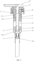
FIG. 2 is a schematic structural cross-section view of the present disclosure when a press head is pressed; -
FIG. 3 is a perspective view of a spring of the present disclosure; -
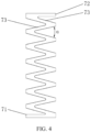
FIG. 4 is a front view of the spring of the present disclosure; and -
FIG. 5 is an exploded view of the present disclosure. - The present disclosure will be further described below in combination with the accompanying drawings:
- As shown in
FIGS. 1 to 5 , an all-plastic combined press pump includes alock bottle cap 1 capable of being fixed on a liquid containing bottle. Apump body 2 and alocking cap 3 capable of fixing thepump body 2 on thelock bottle cap 1 are disposed on thelock bottle cap 1. Aliquid storage chamber 21, acommunication port 22 communicated with theliquid storage chamber 21, a one-way valve 4 capable of controlling thecommunication port 22 to be opened to enable a liquid to enter theliquid storage chamber 21, and a pumping assembly 5 capable of sliding up and down are disposed in thepump body 2. Apress head 6 for driving the pumping assembly 5 to move downwards to enable air pressure to be generated in theliquid storage chamber 21 to extrude the liquid in theliquid storage chamber 21 to flow out is disposed at an upper end of the pumping assembly 5. Aplastic spring 7 for elastically pressing thepress head 6 to drive the pumping assembly 5 to reset upwards to enable negative pressure in theliquid storage chamber 21 to be generated so as to open the one-way valve 4 to suck the liquid into theliquid storage chamber 21 is disposed between thelocking cap 3 and thepress head 6. Theplastic spring 7 includes a first supportingpart 71 abutting against thelocking cap 3, a second supportingpart 72 arranged above the first supportingpart 71 and abutting against thepress head 6, and a plurality of elastic connectingparts 73 arranged between the first supportingpart 71 and the second supportingpart 72 and sequentially connected end to end to form a continuous Z-shaped structure. Specifically, each Z-shaped structure is composed of three elastic connectingparts 73. The elasticity of the plastic spring is increased through the Z-shaped structure, and the plastic spring is integrally formed by the first supporting part, the second supporting part and the plurality of elastic connecting parts. It has a simple structure and is easy to mold and manufacture. In the present disclosure, the metal spring is replaced by the plastic spring with good resilience performance, and the remaining members are made of plastics. When recycling, the press pump can be recycled and remolded by simply removing the spring without disassembly, which has a high production efficiency and is energy-saving and environment-friendly. - An included angle α between two adjacent elastic connecting
parts 73 is 5° to 90°. The pressing within the range of 5° to 90° can also ensure good resilience performance, and also make the effective travel of the plastic spring longer and the range wider. Springs with different elasticities may also be produced according to needs and used in different press pumps. - As shown in
FIG. 3 , the first supportingpart 71, the second supportingpart 72, and the elastic connectingparts 73 are in annular shapes. Specifically, the first supportingpart 71, the second supportingpart 72, and the elastic connectingparts 73 are of circular ring sheet-like structures. The circular ring sheet-like structures corresponding to the first supportingpart 71 and the second supportingpart 72 are parallel to each other. The circular ring sheet-like structures corresponding to the elastic connectingpart 73 are inclined from top to bottom, and two adjacent elastic connectingparts 73 are inclined in opposite directions. With the above structures, the elastic connectingparts 73 have good deformation stability and maintain good elastic force in the axial direction. - In the present disclosure, the pumping assembly 5 includes a
pump rod 51 with an upper end extending through thelocking cap 3 to be inserted into thepress head 6 and a lower end extending into theliquid storage chamber 21, and apiston 52 mounted on thepump rod 51 and capable of moving relative to thepump rod 51 and then driven by thepump rod 51. Aliquid outlet channel 511 communicated with a liquid outlet end of thepress head 6 is disposed in thepump rod 51. Aliquid inlet 512 sealed by thepiston 52 is disposed at a lower end of thepump rod 51. Thepump rod 51 moves downwards relative to thepiston 52 to open theliquid inlet 512 and enable emulsion in theliquid storage chamber 21 to enter theliquid outlet channel 511. When the press head at the top is pressed, the press head drives the pump rod to enable the pump rod to move downwards relative to the piston, and then the liquid inlet is opened. Then, the press head is pressed continuously to enable the pump rod to drive the piston to move downwards to generate air pressure. The liquid in the liquid storage chamber is sent to the liquid outlet end of the press head through the liquid inlet and the liquid outlet channel. When the press head is pressed and the liquid is pumped out, the plastic spring elastically presses the press head to drive the pump rod and the piston to move upwards and reset. The negative pressure is generated in the liquid storage chamber to suck in the liquid from the product bottle for next using. - Specifically, a lower end of the
locking cap 3 is provided with anextension part 31 extending into thepump body 2 for abutting against and positioning thepiston 52 as thepiston 52 moves upwards. An insertedtube 61 extending downwards to be inserted into theextension part 31 is disposed on thepress head 6. Theextension part 31 and the insertedtube 61 surround to form a spring cavity 8 containing theplastic spring 7, to hide theplastic spring 7. - Further, a longitudinally extending
guide runner 311 is disposed on an inner wall of theextension part 31, and aguide sliding block 611 inserted into theguide runner 311 and sliding up and down along theguide runner 311 is disposed on an outer wall of the insertedtube 61. When theguide sliding block 611 and theguide runner 311 are aligned, thepress head 6 may slide up and down relative to thelocking cap 3 when thepress head 6 is pressed. Theguide runner 311 and theguide sliding block 611 serves to guide the sliding of thepress head 6, making the pressing stable. However, when thepress head 6 is rotated to cause theguide sliding block 611 to be not aligned with theguide runner 311, theguide sliding block 611 may abut against the edge step of thelocking cap 3 when thepress head 6 is pressed, and cannot continue to move downwards. This can achieve self-locking of thepress head 6.
Claims (7)
- An all-plastic combined press pump, comprising:
a lock bottle cap (1) capable of being fixed on a liquid containing bottle; a pump body (2) and a locking cap (3) capable of fixing the pump body (2) on the lock bottle cap (1) are disposed on the lock bottle cap (1); a liquid storage chamber (21), a communication port (22) communicated with the liquid storage chamber (21), a one-way valve (4) capable of controlling the communication port (22) to be opened to enable a liquid to enter the liquid storage chamber (21), and a pumping assembly (5) capable of sliding up and down are disposed in the pump body (2); a press head (6) is disposed at an upper end of the pumping assembly (5), which is configured for driving the pumping assembly (5) to move downwards to enable air pressure to be generated in the liquid storage chamber (21) to extrude the liquid in the liquid storage chamber (21) to flow out; a plastic spring (7) is disposed between the locking cap (3) and the press head (6), which is configured for elastically pressing the press head (6) to drive the pumping assembly (5) to reset upwards to enable negative pressure in the liquid storage chamber (21) to be generated so as to open the one-way valve (4) to suck the liquid into the liquid storage chamber (21); and the plastic spring (7) comprises a first supporting part (71) abutting against the locking cap (3), a second supporting part (72) arranged above the first supporting part (71) and abutting against the press head (6), and a plurality of elastic connecting parts (73) arranged between the first supporting part (71) and the second supporting part (72) and sequentially connected end to end to form a continuous Z-shaped structure. - The all-plastic combined press pump according to claim 1, wherein an included angle α between two adjacent elastic connecting parts (73) is 5° to 90°.
- The all-plastic combined press pump according to claim 1, wherein the first supporting part (71), the second supporting part (72), and the elastic connecting parts (73) are in annular shapes.
- The all-plastic combined press pump according to claim 3, wherein the first supporting part (71), the second supporting part (72), and the elastic connecting parts (73) are of circular ring sheet-like structures.
- The all-plastic combined press pump according to claim 1, wherein the pumping assembly (5) comprises a pump rod (51) with an upper end extending through the locking cap (3) to be inserted into the press head (6) and a lower end extending into the liquid storage chamber (21), and a piston (52) mounted on the pump rod (51) and capable of moving relative to the pump rod (51) and then driven by the pump rod (51); a liquid outlet channel (511) communicated with a liquid outlet end of the press head (6) is provided in the pump rod (51); a liquid inlet (512) sealed by the piston (52) is disposed at the lower end of the pump rod (51); and the pump rod (51) is configured to move downwards relative to the piston (52) to open the liquid inlet (512) and enable emulsion in the liquid storage chamber (21) to enter the liquid outlet channel (511).
- The all-plastic combined press pump according to claim 5, wherein a lower end of the locking cap (3) is provided with an extension part (31) extending into the pump body (2) for abutting against and positioning the piston (52) as the piston (52) moves upwards; an inserted tube (61) extending downwards to be inserted into the extension part (31) is disposed on the press head (6); and the extension part (31) and the inserted tube (61) surround to form a spring cavity (8) containing the plastic spring (7).
- The all-plastic combined press pump according to claim 6, wherein a longitudinally extending guide runner (311) is disposed on an inner wall of the extension part (31), and a guide sliding block (611) inserted into the guide runner (311) and sliding up and down along the guide runner (311) is disposed on an outer wall of the inserted tube (61).
Applications Claiming Priority (2)
| Application Number | Priority Date | Filing Date | Title |
|---|---|---|---|
| CN202310949973.9A CN116946558A (en) | 2023-07-28 | 2023-07-28 | All-plastic combined pressing pump |
| PCT/CN2023/120561 WO2025025322A1 (en) | 2023-07-28 | 2023-09-22 | All-plastic combined pressing pump |
Publications (2)
| Publication Number | Publication Date |
|---|---|
| EP4524050A1 true EP4524050A1 (en) | 2025-03-19 |
| EP4524050A4 EP4524050A4 (en) | 2025-08-20 |
Family
ID=88461637
Family Applications (1)
| Application Number | Title | Priority Date | Filing Date |
|---|---|---|---|
| EP23916600.2A Pending EP4524050A4 (en) | 2023-07-28 | 2023-09-22 | COMBINED ALL-PLASTIC PRESS PUMP |
Country Status (4)
| Country | Link |
|---|---|
| US (1) | US20260108902A1 (en) |
| EP (1) | EP4524050A4 (en) |
| CN (1) | CN116946558A (en) |
| WO (1) | WO2025025322A1 (en) |
Family Cites Families (17)
| Publication number | Priority date | Publication date | Assignee | Title |
|---|---|---|---|---|
| FR2651837B1 (en) * | 1989-09-08 | 1993-04-23 | Aerosol Inventions Dev | PRE-ORIENTABLE MANUAL PUMP ON THE CONE OF A CONTAINER. |
| CN103964056B (en) * | 2013-01-31 | 2017-11-17 | 丁要武 | Push type liquid pump |
| CN105035505B (en) * | 2015-08-06 | 2017-09-29 | 浙江正庄实业有限公司 | external spring perfume pump |
| CN212173101U (en) * | 2019-12-24 | 2020-12-18 | 中山市联昌喷雾泵有限公司 | Emulsion pump with safety device |
| CN212221052U (en) * | 2020-02-21 | 2020-12-25 | 中山市美捷时包装制品有限公司 | Emulsion pump with plug cap protection |
| US12173768B2 (en) * | 2020-04-29 | 2024-12-24 | Yonwoo Co., Ltd. | Elastic member and pump assembly including the same |
| KR102635975B1 (en) * | 2020-05-14 | 2024-02-15 | (주)선앤엘 | pump dispenser |
| BR112022023715A2 (en) * | 2020-05-29 | 2023-02-07 | Promens Sa | PUMP FOR DISPENSING A FLUID |
| CN114148626A (en) * | 2020-09-08 | 2022-03-08 | 余姚市绿亚工具有限公司 | Anti-pollution container and anti-pollution liquid pump therefor |
| CN214987291U (en) * | 2021-04-15 | 2021-12-03 | 精英模具(上海)有限公司 | A gas-liquid pressing pump |
| KR102343287B1 (en) * | 2021-08-26 | 2021-12-24 | 이재환 | Spring Having A Structure For Smoothly Guiding The Pumping Of The Pumping Device, And A Pumping Device Having The Same |
| EP4469210A1 (en) * | 2022-01-24 | 2024-12-04 | Aptar Dortmund GmbH | Valve spring, pump, dispensing unit and dispenser |
| CN114803126A (en) * | 2022-06-06 | 2022-07-29 | 中山市美捷时包装制品有限公司 | All-plastic recyclable pressing pump |
| CN115489869B (en) * | 2022-08-05 | 2025-05-23 | 中山市联昌喷雾泵有限公司 | Pumps and liquid containers |
| CN218318321U (en) * | 2022-08-05 | 2023-01-17 | 中山市联昌喷雾泵有限公司 | Push pump and liquid container |
| CN116062308B (en) * | 2023-02-20 | 2024-09-27 | 厦门戴达科技有限公司 | Full plastic liquid pump |
| CN220375248U (en) * | 2023-07-28 | 2024-01-23 | 中山市美捷时包装制品有限公司 | All-plastic combined pressing pump |
-
2023
- 2023-07-28 CN CN202310949973.9A patent/CN116946558A/en active Pending
- 2023-09-22 EP EP23916600.2A patent/EP4524050A4/en active Pending
- 2023-09-22 US US18/832,499 patent/US20260108902A1/en active Pending
- 2023-09-22 WO PCT/CN2023/120561 patent/WO2025025322A1/en active Pending
Also Published As
| Publication number | Publication date |
|---|---|
| WO2025025322A1 (en) | 2025-02-06 |
| US20260108902A1 (en) | 2026-04-23 |
| EP4524050A4 (en) | 2025-08-20 |
| CN116946558A (en) | 2023-10-27 |
Similar Documents
| Publication | Publication Date | Title |
|---|---|---|
| CN110547582A (en) | An external spring waterproof lotion pump | |
| EP4428054A1 (en) | Recyclable all-plastic self-locking pump | |
| US20230241633A1 (en) | Liquid pump | |
| CN212951941U (en) | Improved structure of spray head | |
| CN111746929A (en) | Polymer all-plastic pressing type emulsion nozzle and material preparation method thereof | |
| EP4524050A1 (en) | All-plastic combined pressing pump | |
| CN220375248U (en) | All-plastic combined pressing pump | |
| CN218859271U (en) | Emulsion packing plant | |
| CN113202711B (en) | A pump head and a container having the pump head | |
| CN216128678U (en) | Plastic spring emulsion pump | |
| WO2022052312A1 (en) | Environmentally friendly foam pump | |
| CN209852890U (en) | Environment-friendly emulsion pump | |
| CN220148053U (en) | Waterproof external spring emulsion pump of preventing feed liquor | |
| CN220501461U (en) | Lengthened full-plastic self-locking pump | |
| CN216581922U (en) | Gas-assisted spray head | |
| CN216862336U (en) | Recoverable all-plastic self-locking pump | |
| CN207733823U (en) | A kind of cosmetic makeup multifunctional nozzle | |
| GB2636607A (en) | Elongated all-plastic self-locking pump | |
| CN217893751U (en) | Plastic lotion pump with external plastic spring | |
| WO2023221579A1 (en) | Press pump having back suction function | |
| CN214456770U (en) | A pressurization liquid storage pot for quantitative filling production | |
| CN116946559A (en) | Lengthened full-plastic self-locking pump | |
| CN211845604U (en) | Improved structure of spray head | |
| CN210556604U (en) | Cosmetic bottle | |
| CN224194992U (en) | A plastic pump head with anti-accidental pressing function |
Legal Events
| Date | Code | Title | Description |
|---|---|---|---|
| STAA | Information on the status of an ep patent application or granted ep patent |
Free format text: STATUS: UNKNOWN |
|
| STAA | Information on the status of an ep patent application or granted ep patent |
Free format text: STATUS: THE INTERNATIONAL PUBLICATION HAS BEEN MADE |
|
| PUAI | Public reference made under article 153(3) epc to a published international application that has entered the european phase |
Free format text: ORIGINAL CODE: 0009012 |
|
| STAA | Information on the status of an ep patent application or granted ep patent |
Free format text: STATUS: REQUEST FOR EXAMINATION WAS MADE |
|
| 17P | Request for examination filed |
Effective date: 20240830 |
|
| AK | Designated contracting states |
Kind code of ref document: A1 Designated state(s): AL AT BE BG CH CY CZ DE DK EE ES FI FR GB GR HR HU IE IS IT LI LT LU LV MC ME MK MT NL NO PL PT RO RS SE SI SK SM TR |
|
| REG | Reference to a national code |
Ref country code: DE Ref legal event code: R079 Free format text: PREVIOUS MAIN CLASS: B65D0047340000 Ipc: B05B0011100000 |
|
| A4 | Supplementary search report drawn up and despatched |
Effective date: 20250721 |
|
| RIC1 | Information provided on ipc code assigned before grant |
Ipc: B05B 11/10 20230101AFI20250715BHEP |