EP4524046A2 - Elongated object label applicator guide - Google Patents
Elongated object label applicator guide Download PDFInfo
- Publication number
- EP4524046A2 EP4524046A2 EP25154033.2A EP25154033A EP4524046A2 EP 4524046 A2 EP4524046 A2 EP 4524046A2 EP 25154033 A EP25154033 A EP 25154033A EP 4524046 A2 EP4524046 A2 EP 4524046A2
- Authority
- EP
- European Patent Office
- Prior art keywords
- elongated object
- guide
- label applicator
- label
- wrapping mechanism
- Prior art date
- Legal status (The legal status is an assumption and is not a legal conclusion. Google has not performed a legal analysis and makes no representation as to the accuracy of the status listed.)
- Pending
Links
Images



Classifications
-
- B—PERFORMING OPERATIONS; TRANSPORTING
- B65—CONVEYING; PACKING; STORING; HANDLING THIN OR FILAMENTARY MATERIAL
- B65C—LABELLING OR TAGGING MACHINES, APPARATUS, OR PROCESSES
- B65C3/00—Labelling other than flat surfaces
- B65C3/02—Affixing labels to elongated objects, e.g. wires, cables, bars, tubes
-
- B—PERFORMING OPERATIONS; TRANSPORTING
- B65—CONVEYING; PACKING; STORING; HANDLING THIN OR FILAMENTARY MATERIAL
- B65C—LABELLING OR TAGGING MACHINES, APPARATUS, OR PROCESSES
- B65C9/00—Details of labelling machines or apparatus
- B65C9/08—Label feeding
- B65C9/18—Label feeding from strips, e.g. from rolls
-
- B—PERFORMING OPERATIONS; TRANSPORTING
- B65—CONVEYING; PACKING; STORING; HANDLING THIN OR FILAMENTARY MATERIAL
- B65C—LABELLING OR TAGGING MACHINES, APPARATUS, OR PROCESSES
- B65C9/00—Details of labelling machines or apparatus
- B65C9/40—Controls; Safety devices
- B65C9/42—Label feed control
Definitions
- the invention relates to a label applicator guide for use in labeling of elongated objects; more particularly, the invention relates to a guide for placing wrapping labels at a set location about wires, cables, and the like.
- Labeling of wires and cables has traditionally been accomplished manually or by way of apparatuses requiring cumbersome, noisy hydraulic or high-pressure air lines. Typically, such machines grasp two points of a section of the wire and pull this section of wire taut. Once the wire is pulled taut, a label applicator or platform orbits around the taut section of wire to apply the label to the wire. This labeler must be capable of orbiting around the wire while applying an appropriate amount and type of pressure between the labeler and the wire. Because the wire or object to be wrapped may take on various shapes or sizes, this can complicate the design and operation of such wire labelers.
- a label applicator such as the one disclosed in U.S. Patent Application 16/279,298 , it is desirable to apply a label at a set or specific distance from an end of a wire, cable, and the like.
- industry standards and requirements determine a set or measured distance from the end of the wire or cable in which the label is to be applied for consistency, clarity, and safety.
- Present label applicators such as the Wraptor A6500 Wrap Printer Applicator manufactured by Brady Worldwide, Inc., include a fixed measurement indicia/indicator for measuring the location of the applied label from the end of the wire or cable.
- Fixed measurement indicia/indicators and other present measurement application lack the ability to place the wire or cable a set or measured distance from the end of the wire or cable and hold that measurement while simultaneously feeding the wire into the label applicator. Operators or users must measure by a visual estimate when feeding the wire or cable into the label applicator.
- Current label applicators lack the ability to safely and consistently label a wire or cable at a set or measured distance from the end of the wire or cable
- an elongated object label applicator of the present invention may include a wrapping mechanism configured to apply a label to an elongated object and a label applicator guide including a base and a controller that is moveably secured to the base adjacent to the wrapping mechanism to guide the elongated object into the wrapping mechanism to apply the label.
- the controller of the elongated object label applicator may be moveably secured to the base in a pivoting relationship through a first knuckle of the controller pivotably connected to a second knuckle of the base, with a pin extending through the first knuckle and second knuckle.
- the base of the elongated object label applicator includes a top portion, side portion, and base portion in a C-shaped configuration forming a channel and the channel of the base mates to a base plate of the elongated object label applicator.
- the label applicator guide of the elongated object label applicator includes indicia for measuring a length of the elongated object placed in the wrapping mechanism.
- the controller of the elongated object label applicator pivots about the base to guide the elongated object into the wrapping mechanism.
- the wrapping mechanism of the elongated object label applicator includes a wire guide configured to cradle the elongated object and direct the elongated object into a central portion of the wrapping mechanism, and the controller is configured to move in unison with the wire guide.
- the controller of the elongated object label applicator includes a first support extending from the base and a second support extending from the first support such that the second support is planar with a wire guide of the wrapping mechanism.
- the second support of the elongated object label applicator includes indicia for measuring a length of the elongated object placed in the wrapping mechanism.
- a label applicator guide includes a base configured to be attached to an elongated object label applicator, and a controller including a first support extending from the base and a second support extending from the first support such that the second support is configured to be planar with a portion of the wrapping mechanism.
- the controller is moveably secured to the base through a first knuckle of the controller being pivotably connected to a second knuckle of the base, with a pin extending through the first knuckle and second knuckle.
- the base of the label applicator guide includes a top portion, side portion, and base portion in a C-shaped configuration forming a channel and wherein the channel of the base is configured to mate to an elongated object label applicator.
- the label applicator guide may also include indicia configured to measure a length of an elongated object placed in a wrapping mechanism.
- a method of applying an adhesive label to an elongated object at a set distance comprising the steps of feeding a label from a source of labels to a wrapping mechanism of an elongated object label applicator; aligning an elongated object with indicia of a label applicator guide; placing the elongated object within a wire guide of the wrapping mechanism; depressing the wire guide and label applicator guide to place the elongated object within the wrapping mechanism; and rotating a rotational device of the wrapping mechanism about an axis of rotation to apply the label.
- the disclosed label applicator guide solves or improves upon one or more of the noted disadvantages with presently known elongated object label applicators and current fixed measurement indicators.
- the present invention of a label applicator guide Provides for a consistent and safe application of a label to a wire or cable at a set or measured distance from the end of the wire or cable.
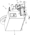
- FIG. 1 depicts an elongated object label applicator 10 with an attached a label applicator guide 100.
- label applicators 10 are apparatuses for applying printed labels to wires, cables or other elongated objects of varying diameters. Labels are wrapped around the objects without spinning the objects about their elongated longitudinal axis. The apparatuses are particularly useful for label types that require that the label be wrapped around an object using more than one revolution. Self-laminating labels are one such type, requiring a transparent end of the label to be wrapped over top of a printed region to provide protection to the printed content.
- Label applicators 10 are comprised of several systems. These systems include a label applicator or printer 12, a media roller or incoming conveyor 14, a label peel-and-present mechanism 16, and a wrapping mechanism 18.
- the wrapping mechanism 18 includes a rotational device driven by a driver as further detailed in U.S. Patent Application 16/279,298 .
- the wrapping mechanism 18 depicted in FIG. 1 further includes a first wire guide 20a and a second wire guide 20b.
- the wire guides 20a, 20b will be described further below.
- the present invention of the label applicator guide 100 is configured to be mounted to the label applicator to accurately apply a label at a set distance within the wrapping mechanism all in a uniform motion.
- the label applicator guide 100 is mounted directly adjacent the wrapping mechanism 18.
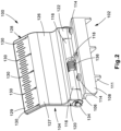
- the label applicator guide 100 includes a base 102 and a controller 104.
- the base 102 includes a top 106, side 108, and bottom 110.
- the top 106, side 108, and bottom 110 are in a C-shaped configuration and form a channel 112.
- Set screws 114 may be found on the top 106 of the base 102.
- the set screws 114 function to secure the base 102 to the label applicator 10.
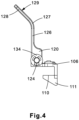
- the bottom 110 may include wings 111 as depicted in FIGS. 2-4 .
- the wings 111 are used to add strength to the bottom 110 and direct forces through the base 102 during tightening of the set screws 114.
- the base 102 further includes base knuckles 116 extending from the top 106 of the base 102.
- the base knuckles 116 include an opening 118.
- the base knuckles 116 and opening 118 allow for the base 102 to pivotably attach to the controller 104.
- the controller 104 includes a bottom portion 120.
- the bottom portion 120 includes a wider profile ( FIG. 4 ) than the rest of the controller 104.
- the wider profile of the bottom portion 120 accommodates guide knuckles 122.
- the guide knuckles 122 include an opening 124.
- the guide knuckles 122 and opening 124 allow for the controller 104 to hingedly or pivotably attached to the base 102.
- a first support 126 extends from the base portion 120.
- the first support 126 is generally planar with the base portion 120 and extends the width of the controller 104.
- a bend 127 is connected to the first support 126.
- a second support 128 is connected to the bend 127 and extends from the first support 126.
- the second support 128 includes a front face 129.
- the second support 128 extends away from the first support 126 at an angle.
- the second support 128 may also be planar with the first support 126.
- the orientation of the second support 128 may be determined by the orientation of the wrapping mechanism 18, such that the front face 129 of the second support 128 is planar with a portion of the wrapping mechanism 18.
- the second support 128 may include indicia or measurement markings 130 along the front face 129 as depicted in FIG. 2 .
- the indicia 130 of FIG. 2 are depicted in the units of inches, however, metric units or any other indicia indicating measurement units may be utilized.
- the indicia 130 of the label applicator guide 100 will be further described below.
- the base 102 is hingedly connected to the controller 104 by a pin 132.
- the pin 132 extends through the openings 118 in the base 102 and the openings 124 in the controller 104.
- the pin 132 may be fastened in place using a fastener 134, such as an E-clip, as depicted in FIGS. 2-4 . It is contemplated that other joining and fastening mechanisms may be implemented in place of the pin 124 and E-clip 134 to pivotably join the base 102 to the controller 104.
- a retention spring 136 is located between the base knuckles 116 and encompasses the pin 132 as is depicted in FIGS. 2 and 3 .
- the retention spring 136 includes a portion mounted to the base 102 and a portion mounted to the controller 104.
- the retention spring 136 may be to keep the controller 104 in a vertically biased position as depicted in FIGS. 2-4 .
- FIG. 5 depicts the label applicator guide 100 connected to the label applicator 10 with a label 30 presented for attachment to an elongated object.
- the base 102 of the label applicator guide 100 is mounted to a base plate 24 of the label applicator 10. As depicted in FIG. 5 , the base plate 24 mounts within the channel 112 of the label applicator 100.
- the set screws 114 are tightened to affix the label applicator guide 100 to the label applicator.
- the label applicator guide 100 depicted in FIG. 5 is mounted onto the base plate 24 of the label applicator 10, directly adjacent to the wrapping mechanism 18.
- the wrapping mechanism 18 includes the first wire guide 20a and second wire guide 20b.
- the first wire guide 20a and second wire guide 20b are located on each side of a central portion 70 of the wrapping mechanism 18.
- the first wire guide 20a and second wire guide 20b each include guide posts 22a, 22b and first and second finger grips 26a, 26b.
- the guide posts 22a, 22b extend up from the wire guides 20a, 20b.
- the guide posts 22a, 22b direct the wire or cable to the central portion 70 of the wrapping mechanism 18.
- the finger grips 26a, 26b extend horizontally from the guide posts 22a, 22b.
- the finger grips 26a, 26b are configured to support the elongated object within the wrapping mechanism 18.
- the first wire guide 20a and second wire guide 20b act as sleds to guide the elongated object into the central portion 70 of the wrapping mechanism 18 for the label 30 to be applied by the wrapping mechanism 18 as described in U.S. Patent Application 16/279,298 .
- a free end 28 of the finger grip 26a may extend over an edge of the controller 104 and align with the indicia 130.
- the retention spring 136 can act a force upon the controller 104 and retain the controller 104 against the finger grip 26a.
- the label applicator guide 100 is mounted to the base plate 24 of the label applicator 10 such that the measurement of the indicia 130 correlate with the distance from the label 30 within the central portion 70 of the wrapping mechanism 18.
- the measurement may be taken from any point on the label 30 within the central portion 70.
- the measurement is taken from the edge of the label closest to the end of the elongated object 82.
- the indicia 130 marked as "1" noted at A in FIG. 5 denotes a measured distance of 1 inch from the label 30.
- the indicia 130 marked as "3" noted at B denotes a measured distance of 3 inches from the label 30.
- the indicia 130 depicted in the figures are in the units of inches, however, metric units or any other indicia indicating measurement units or lengths correlating to a length of the elongated object may be utilized.
- FIGS. 6 and 7 depict the label applicator guide 100 connected to the label applicator 10 and including an elongated object 82.
- the elongated object 82 includes a first end 84 positioned over the label applicator guide 100 and a labeling section 86 positioned between the wire guides 20a, 20b.
- the first end 84 is a termination end of the elongated object 82, near where the label 30 is to be placed.
- the label section 86 is the portion of the elongated object 86 where the label 30 is intended to be placed.
- FIG. 6 depicts the label section 86 the elongated object 82 positioned between the wire guides 20a, 20b of the wrapping mechanism 18 in preparation for applying the label 30.
- the label 30 may be presented for labeling, with the adhesive side up as described in U.S. Patent Application 16/279,298 .
- a leading edge 32 of the label 30 will extend past a center of the central portion 70 in the wrapping mechanism 18.
- the user may wish to apply the label 30 at a set distance when using the label applicator 10.
- the user may align the end 84 of the elongated object 82 with the selected measurement indicia 130, i.e. 1, 2, 3, etc.
- a user may place labeling section 86 of the elongated object 82 between the wire guides 20a, 20b of the wrapping mechanism 18 so that the surface of the object 82 first contacts an adhesive on the adhesive side of the label 86.
- the user may then depress the elongated object 82 into the wrapping mechanism 18 by depressing the wire guides 20a, 20b along with the elongated object 82 into the central portion 70.
- the wire guides 20a, 20b will follow a linear path and travel into the wrapping mechanism 18.
- the first finger grip 26a of wire guide 20a will act on the controller 104 and cause the controller 104 to rotate with the linear movement of wire guide 20a.
- the user may maintain control of the elongated object 82 against the label applicator guide 100 by holding the elongated object 82 against the controller 104 and wire guide 20a at the same time, while the wire guides 20a, 20b, move linearly into the central portion and at the same time the controller 104 pivots as a result of the wire guides 20a, 20b, linear movement.
- FIG. 7 depicts the elongated object 82 within the central portion 70 of the wrapping mechanism for application of the label.
Landscapes
- Labeling Devices (AREA)
Abstract
Description
- The invention relates to a label applicator guide for use in labeling of elongated objects; more particularly, the invention relates to a guide for placing wrapping labels at a set location about wires, cables, and the like.
- Labeling of wires and cables has traditionally been accomplished manually or by way of apparatuses requiring cumbersome, noisy hydraulic or high-pressure air lines. Typically, such machines grasp two points of a section of the wire and pull this section of wire taut. Once the wire is pulled taut, a label applicator or platform orbits around the taut section of wire to apply the label to the wire. This labeler must be capable of orbiting around the wire while applying an appropriate amount and type of pressure between the labeler and the wire. Because the wire or object to be wrapped may take on various shapes or sizes, this can complicate the design and operation of such wire labelers.
- More recently, elongated object label applicators have been developed to solve the problems discussed above and other problems, and to provide advantages and aspects not provided by prior labeling devices of this type. One such elongated object label applicator is disclosed in
U.S. ., which is incorporated by reference herein.Patent Application 16/279,298 assigned to Panduit Corp - In using a label applicator such as the one disclosed in
U.S. , it is desirable to apply a label at a set or specific distance from an end of a wire, cable, and the like. In many instances, industry standards and requirements determine a set or measured distance from the end of the wire or cable in which the label is to be applied for consistency, clarity, and safety. Present label applicators, such as the Wraptor A6500 Wrap Printer Applicator manufactured by Brady Worldwide, Inc., include a fixed measurement indicia/indicator for measuring the location of the applied label from the end of the wire or cable. Fixed measurement indicia/indicators and other present measurement application lack the ability to place the wire or cable a set or measured distance from the end of the wire or cable and hold that measurement while simultaneously feeding the wire into the label applicator. Operators or users must measure by a visual estimate when feeding the wire or cable into the label applicator. Current label applicators lack the ability to safely and consistently label a wire or cable at a set or measured distance from the end of the wire or cablePatent Application 16/279,298 - The present invention is provided to solve the problems of fixed measurement indicia discussed above and other problems, and to provide advantages and aspects not provided in recent labeling applicators of this type. A full discussion of the features and advantages of the present invention is deferred to the following detailed description, which proceeds with reference to the accompanying drawings.
- In one example, according to the teachings of the present invention, an elongated object label applicator of the present invention may include a wrapping mechanism configured to apply a label to an elongated object and a label applicator guide including a base and a controller that is moveably secured to the base adjacent to the wrapping mechanism to guide the elongated object into the wrapping mechanism to apply the label.
- In one example, the controller of the elongated object label applicator may be moveably secured to the base in a pivoting relationship through a first knuckle of the controller pivotably connected to a second knuckle of the base, with a pin extending through the first knuckle and second knuckle.
- In one example, the base of the elongated object label applicator includes a top portion, side portion, and base portion in a C-shaped configuration forming a channel and the channel of the base mates to a base plate of the elongated object label applicator.
- In one example, the label applicator guide of the elongated object label applicator includes indicia for measuring a length of the elongated object placed in the wrapping mechanism.
- In one example, the controller of the elongated object label applicator pivots about the base to guide the elongated object into the wrapping mechanism.
- In one example, the wrapping mechanism of the elongated object label applicator includes a wire guide configured to cradle the elongated object and direct the elongated object into a central portion of the wrapping mechanism, and the controller is configured to move in unison with the wire guide.
- In one example, the controller of the elongated object label applicator includes a first support extending from the base and a second support extending from the first support such that the second support is planar with a wire guide of the wrapping mechanism.
- In one example, the second support of the elongated object label applicator includes indicia for measuring a length of the elongated object placed in the wrapping mechanism.
- In one example, according to the teachings of the present invention, a label applicator guide includes a base configured to be attached to an elongated object label applicator, and a controller including a first support extending from the base and a second support extending from the first support such that the second support is configured to be planar with a portion of the wrapping mechanism. The controller is moveably secured to the base through a first knuckle of the controller being pivotably connected to a second knuckle of the base, with a pin extending through the first knuckle and second knuckle.
- In one example, the base of the label applicator guide includes a top portion, side portion, and base portion in a C-shaped configuration forming a channel and wherein the channel of the base is configured to mate to an elongated object label applicator.
- In one example, the label applicator guide may also include indicia configured to measure a length of an elongated object placed in a wrapping mechanism.
- In one example, according to the teachings of the present invention, a method of applying an adhesive label to an elongated object at a set distance comprising the steps of feeding a label from a source of labels to a wrapping mechanism of an elongated object label applicator; aligning an elongated object with indicia of a label applicator guide; placing the elongated object within a wire guide of the wrapping mechanism; depressing the wire guide and label applicator guide to place the elongated object within the wrapping mechanism; and rotating a rotational device of the wrapping mechanism about an axis of rotation to apply the label.
- To understand the present invention, it will now be described by way of example, with reference to the accompanying drawings in which:
-
FIG. 1 is a perspective view of the present invention installed on an elongated label applicator; -
FIG. 2 is a front perspective view of the present invention of a label applicator guide; -
FIG. 3 is a rear perspective view of the label applicator guide ofFIG. 2 ; -
FIG. 4 is a side view of the label applicator guide ofFIG. 2 ; -
FIG. 5 is a partial perspective view ofFIG. 1 , depicting the label applicator guide and elongated label applicator; -
FIG. 6 is the label applicator guide and elongated label applicator ofFIG. 5 with a measured wire or cable that is prepared for labeling; and -
FIG. 7 is the label applicator guide and elongated label applicator ofFIG. 5 , with the wire or cable inserted into the wrapping mechanism for labeling. - The disclosed label applicator guide solves or improves upon one or more of the noted disadvantages with presently known elongated object label applicators and current fixed measurement indicators. The present invention of a label applicator guide Provides for a consistent and safe application of a label to a wire or cable at a set or measured distance from the end of the wire or cable.
- Turning to the drawings,
FIG. 1 depicts an elongatedobject label applicator 10 with an attached alabel applicator guide 100. - As discussed above,
label applicators 10 are apparatuses for applying printed labels to wires, cables or other elongated objects of varying diameters. Labels are wrapped around the objects without spinning the objects about their elongated longitudinal axis. The apparatuses are particularly useful for label types that require that the label be wrapped around an object using more than one revolution. Self-laminating labels are one such type, requiring a transparent end of the label to be wrapped over top of a printed region to provide protection to the printed content. -
Label applicators 10 are comprised of several systems. These systems include a label applicator orprinter 12, a media roller or incomingconveyor 14, a label peel-and-present mechanism 16, and awrapping mechanism 18. Thewrapping mechanism 18 includes a rotational device driven by a driver as further detailed inU.S. Patent Application 16/279,298wrapping mechanism 18 depicted inFIG. 1 further includes afirst wire guide 20a and asecond wire guide 20b. Thewire guides label applicator guide 100 is configured to be mounted to the label applicator to accurately apply a label at a set distance within the wrapping mechanism all in a uniform motion. - As depicted in
FIG. 1 , thelabel applicator guide 100 is mounted directly adjacent thewrapping mechanism 18. Referring toFIGS. 2-4 , thelabel applicator guide 100 includes abase 102 and acontroller 104. Thebase 102 includes atop 106,side 108, andbottom 110. Thetop 106,side 108, andbottom 110 are in a C-shaped configuration and form achannel 112. Setscrews 114 may be found on thetop 106 of thebase 102. Theset screws 114 function to secure thebase 102 to thelabel applicator 10. Thebottom 110 may includewings 111 as depicted inFIGS. 2-4 . Thewings 111 are used to add strength to thebottom 110 and direct forces through thebase 102 during tightening of theset screws 114. - The
base 102 further includesbase knuckles 116 extending from thetop 106 of thebase 102. Thebase knuckles 116 include an opening 118. Thebase knuckles 116 andopening 118 allow for the base 102 to pivotably attach to thecontroller 104. - As depicted in
FIGS. 2-4 , thecontroller 104 includes abottom portion 120. Thebottom portion 120 includes a wider profile (FIG. 4 ) than the rest of thecontroller 104. The wider profile of thebottom portion 120 accommodates guideknuckles 122. Theguide knuckles 122 include anopening 124. Theguide knuckles 122 andopening 124 allow for thecontroller 104 to hingedly or pivotably attached to thebase 102. - As depicted in
FIG. 2 , afirst support 126 extends from thebase portion 120. Thefirst support 126 is generally planar with thebase portion 120 and extends the width of thecontroller 104. Abend 127 is connected to thefirst support 126. Asecond support 128 is connected to thebend 127 and extends from thefirst support 126. Thesecond support 128 includes afront face 129. As depicted inFIGS. 2-4 , thesecond support 128 extends away from thefirst support 126 at an angle. Alternatively, thesecond support 128 may also be planar with thefirst support 126. The orientation of thesecond support 128 may be determined by the orientation of thewrapping mechanism 18, such that thefront face 129 of thesecond support 128 is planar with a portion of thewrapping mechanism 18. - The
second support 128 may include indicia ormeasurement markings 130 along thefront face 129 as depicted inFIG. 2 . Theindicia 130 ofFIG. 2 are depicted in the units of inches, however, metric units or any other indicia indicating measurement units may be utilized. Theindicia 130 of thelabel applicator guide 100 will be further described below. - As depicted in
FIGS. 2-4 , thebase 102 is hingedly connected to thecontroller 104 by a pin 132. The pin 132 extends through theopenings 118 in thebase 102 and theopenings 124 in thecontroller 104. The pin 132 may be fastened in place using afastener 134, such as an E-clip, as depicted inFIGS. 2-4 . It is contemplated that other joining and fastening mechanisms may be implemented in place of thepin 124 andE-clip 134 to pivotably join the base 102 to thecontroller 104. - A
retention spring 136 is located between thebase knuckles 116 and encompasses the pin 132 as is depicted inFIGS. 2 and3 . Theretention spring 136 includes a portion mounted to thebase 102 and a portion mounted to thecontroller 104. Theretention spring 136 may be to keep thecontroller 104 in a vertically biased position as depicted inFIGS. 2-4 . -
FIG. 5 depicts thelabel applicator guide 100 connected to thelabel applicator 10 with alabel 30 presented for attachment to an elongated object. Thebase 102 of thelabel applicator guide 100 is mounted to abase plate 24 of thelabel applicator 10. As depicted inFIG. 5 , thebase plate 24 mounts within thechannel 112 of thelabel applicator 100. Theset screws 114 are tightened to affix thelabel applicator guide 100 to the label applicator. - The
label applicator guide 100 depicted inFIG. 5 is mounted onto thebase plate 24 of thelabel applicator 10, directly adjacent to thewrapping mechanism 18. As referenced above, thewrapping mechanism 18 includes thefirst wire guide 20a andsecond wire guide 20b. Thefirst wire guide 20a andsecond wire guide 20b are located on each side of acentral portion 70 of thewrapping mechanism 18. Thefirst wire guide 20a andsecond wire guide 20b each includeguide posts central portion 70 of thewrapping mechanism 18. The finger grips 26a, 26b extend horizontally from theguide posts wrapping mechanism 18. - The
first wire guide 20a andsecond wire guide 20b act as sleds to guide the elongated object into thecentral portion 70 of thewrapping mechanism 18 for thelabel 30 to be applied by thewrapping mechanism 18 as described inU.S. Patent Application 16/279,298 - A
free end 28 of the finger grip 26a may extend over an edge of thecontroller 104 and align with theindicia 130. In this configuration, theretention spring 136 can act a force upon thecontroller 104 and retain thecontroller 104 against the finger grip 26a. - The
label applicator guide 100, as depicted inFIG. 5 , is mounted to thebase plate 24 of thelabel applicator 10 such that the measurement of theindicia 130 correlate with the distance from thelabel 30 within thecentral portion 70 of thewrapping mechanism 18. The measurement may be taken from any point on thelabel 30 within thecentral portion 70. Typically, the measurement is taken from the edge of the label closest to the end of theelongated object 82. Specifically, theindicia 130 marked as "1" noted at A inFIG. 5 , denotes a measured distance of 1 inch from thelabel 30. Likewise, theindicia 130 marked as "3" noted at B denotes a measured distance of 3 inches from thelabel 30. Theindicia 130 depicted in the figures are in the units of inches, however, metric units or any other indicia indicating measurement units or lengths correlating to a length of the elongated object may be utilized. -
FIGS. 6 and7 depict thelabel applicator guide 100 connected to thelabel applicator 10 and including anelongated object 82. Theelongated object 82 includes afirst end 84 positioned over thelabel applicator guide 100 and alabeling section 86 positioned between the wire guides 20a, 20b. Thefirst end 84 is a termination end of theelongated object 82, near where thelabel 30 is to be placed. Thelabel section 86 is the portion of theelongated object 86 where thelabel 30 is intended to be placed. -
FIG. 6 depicts thelabel section 86 theelongated object 82 positioned between the wire guides 20a, 20b of thewrapping mechanism 18 in preparation for applying thelabel 30. Thelabel 30 may be presented for labeling, with the adhesive side up as described inU.S. Patent Application 16/279,298edge 32 of thelabel 30 will extend past a center of thecentral portion 70 in thewrapping mechanism 18. - The user may wish to apply the
label 30 at a set distance when using thelabel applicator 10. The user may align theend 84 of theelongated object 82 with the selectedmeasurement indicia 130, i.e. 1, 2, 3, etc. While holding theend 84 of theelongated object 82 at the selected indicia point, a user may placelabeling section 86 of theelongated object 82 between the wire guides 20a, 20b of thewrapping mechanism 18 so that the surface of theobject 82 first contacts an adhesive on the adhesive side of thelabel 86. - The user may then depress the
elongated object 82 into thewrapping mechanism 18 by depressing the wire guides 20a, 20b along with theelongated object 82 into thecentral portion 70. The wire guides 20a, 20b will follow a linear path and travel into thewrapping mechanism 18. As the wire guides 20a, 20b travel into thewrapping mechanism 18, the first finger grip 26a ofwire guide 20a will act on thecontroller 104 and cause thecontroller 104 to rotate with the linear movement ofwire guide 20a. During this operation, the user may maintain control of theelongated object 82 against thelabel applicator guide 100 by holding theelongated object 82 against thecontroller 104 andwire guide 20a at the same time, while the wire guides 20a, 20b, move linearly into the central portion and at the same time thecontroller 104 pivots as a result of the wire guides 20a, 20b, linear movement. -
FIG. 7 depicts theelongated object 82 within thecentral portion 70 of the wrapping mechanism for application of the label. Once theelongated object 82 is inserted fully into thecentral portion 70, the rotational device (not shown) of thewrapping mechanism 18 orbits about theobject 82 causing the label 30 (not viewable) to be pushed against theobject 82 from all angles as detailed inU.S. Patent Application 16/279,298elongated object 82 from thewrapping mechanism 18. The above process can be repeated for labeling additional elongated objects. - The illustrations of the embodiments described herein are intended to provide a general understanding of the structure of the various examples. The illustrations are not intended to serve as a complete description of all of the elements and features of apparatus and systems that utilize the structures or methods described herein. Many other embodiments may be apparent to those of skill in the art upon reviewing the disclosure. Other embodiments may be utilized and derived from the disclosure, such that structural and logical substitutions and changes may be made without departing from the scope of the disclosure. Additionally, the illustrations are merely representational and may not be drawn to scale. Certain proportions within the illustrations may be exaggerated, while other proportions may be minimized. Accordingly, the disclosure and the figures are to be regarded as illustrative rather than restrictive.
- Examples of the present disclosure are set out in the following numbered clauses.
- 1. An elongated object label applicator comprising:
- a wrapping mechanism configured to apply a label to an elongated object and
- a label applicator guide including a base and a controller moveably secured to the base adjacent to the wrapping mechanism to guide the elongated object into the wrapping mechanism to apply the label.
- 2. The elongated object label applicator of clause 1, wherein the controller is moveably secured to the base in a pivoting relationship through a first knuckle of the controller pivotably connected to a second knuckle of the base, with a pin extending through the first knuckle and second knuckle.
- 3. The elongated object label applicator of clause 1, wherein the base includes a top portion, side portion, and base portion in a C-shaped configuration forming a channel and wherein the channel of the base mates to a base plate of the elongated object label applicator.
- 4. The elongated object label applicator of clause 1, wherein the label applicator guide includes indicia for measuring a length of the elongated object placed in the wrapping mechanism.
- 5. The elongated object label applicator of clause 1, wherein the controller pivots about the base to guide the elongated object into the wrapping mechanism.
- 6. The elongated object label applicator of clause 1, wherein the wrapping mechanism includes a wire guide configured to cradle the elongated object and direct the elongated object into a central portion of the wrapping mechanism, and wherein the controller is configured to move in unison with the wire guide.
- 7. The elongated object label applicator of clause 1, wherein the controller includes a first support extending from the base and a second support extending from the first support such that the second support is planar with a wire guide of the wrapping mechanism.
- 8. The elongated object label applicator of clause 7, wherein the second support includes indicia for measuring a length of the elongated object placed in the wrapping mechanism.
- 9. The elongated object label applicator of clause 8, wherein the controller is moveably secured to the base through a first knuckle of the controller being pivotably connected to a second knuckle of the base, with a pin extending through the first knuckle and second knuckle.
- 10. The elongated object label applicator of clause 9, wherein the controller pivots about the base to guide the elongated object into the wrapping mechanism.
- 11. A label applicator guide comprising:
a base configured to be attached to an elongated object label applicator, and a controller including a first support extending from the base and a second support extending from the first support such that the second support is configured to be planar with a portion of the wrapping mechanism, wherein the controller is moveably secured to the base through a first knuckle of the controller being pivotably connected to a second knuckle of the base, with a pin extending through the first knuckle and second knuckle. - 12. The label applicator guide of clause 11, wherein the base includes a top portion, side portion, and base portion in a C-shaped configuration forming a channel and wherein the channel of the base is configured to mate to an elongated object label applicator.
- 13. The label applicator guide of clause 11, further including indicia configured to measure a length of an elongated object placed in a wrapping mechanism.
- 14. A method of applying an adhesive label to an elongated object at a set distance comprising the steps of:
- feeding a label from a source of labels to a wrapping mechanism of an elongated object label applicator;
- aligning an elongated object with indicia of a label applicator guide;
- placing the elongated object within a wire guide of the wrapping mechanism;
- depressing the wire guide and label applicator guide to place the elongated object within the wrapping mechanism; and
Claims (9)
- An elongated object label applicator (10) comprising:
a wrapping mechanism (18) comprising:a first wire guide (20a) and second wire guide (20b) located on opposite sides of a central portion (70), each guide including guide posts (22a, 22b) configured to receive an elongated object (82) and direct the elongated object to the central portion, such that a labeling section (86) of the elongated object is positioned between the first and second wire guides,wherein the first and second wire guides are configured to move into the wrapping mechanism and wherein the movement of the first and second wire guides causes the label (30) to be pushed against the object by the wrapping mechanism at the labelling section; anda label applicator guide (100) including indicia (130) for measuring a length of the elongated object placed in the wrapping mechanism. - The elongated object label applicator of claim 1, wherein the measurement indicia (130) are suitable for aligning an end (84) of the elongated object such that the labeling section is positioned between the first and second wire guides.
- The elongated object label applicator of any preceding claim, wherein the label applicator guide is configured to move with respect to the wrapping mechanism.
- The elongated object label applicator of any preceding claim, the label applicator guide further comprising a base including a top portion, side portion, and base portion in a C-shaped configuration forming a channel and wherein the channel of the base is configured to mate to a base plate of the elongated object label applicator.
- The elongated object label applicator of claim 4, the label applicator guide further comprising a controller moveably secured to the base in a pivoting relationship through a first knuckle of the controller pivotably connected to a second knuckle of the base, with a pin extending through the first knuckle and second knuckle, wherein the controller is configured to guide the elongated object into the wrapping mechanism to apply the label.
- The elongated object label applicator of claim 5, wherein the controller is configured to pivot about the base to guide the elongated object into the wrapping mechanism.
- The elongated object label application of any preceding claim, wherein the indicia are numerical indicia according to a metric unit of measurement.
- The elongated object label application of any preceding claim, wherein the indicia are numerical indicia according to a numeric unit of measurement including inches.
- The elongated object label application of any preceding claim, wherein the indicia are numerical indicia having assigned values such that a smaller numerical value is assigned to a position on the label applicator guide closer to the wrapping mechanism.
Applications Claiming Priority (2)
| Application Number | Priority Date | Filing Date | Title |
|---|---|---|---|
| US16/507,708 US11305909B2 (en) | 2019-07-10 | 2019-07-10 | Elongated object label applicator guide |
| EP20183513.9A EP3763626B1 (en) | 2019-07-10 | 2020-07-01 | Elongated object label applicator guide |
Related Parent Applications (2)
| Application Number | Title | Priority Date | Filing Date |
|---|---|---|---|
| EP20183513.9A Division-Into EP3763626B1 (en) | 2019-07-10 | 2020-07-01 | Elongated object label applicator guide |
| EP20183513.9A Division EP3763626B1 (en) | 2019-07-10 | 2020-07-01 | Elongated object label applicator guide |
Publications (2)
| Publication Number | Publication Date |
|---|---|
| EP4524046A2 true EP4524046A2 (en) | 2025-03-19 |
| EP4524046A3 EP4524046A3 (en) | 2025-06-18 |
Family
ID=71452033
Family Applications (2)
| Application Number | Title | Priority Date | Filing Date |
|---|---|---|---|
| EP25154033.2A Pending EP4524046A3 (en) | 2019-07-10 | 2020-07-01 | Elongated object label applicator guide |
| EP20183513.9A Active EP3763626B1 (en) | 2019-07-10 | 2020-07-01 | Elongated object label applicator guide |
Family Applications After (1)
| Application Number | Title | Priority Date | Filing Date |
|---|---|---|---|
| EP20183513.9A Active EP3763626B1 (en) | 2019-07-10 | 2020-07-01 | Elongated object label applicator guide |
Country Status (4)
| Country | Link |
|---|---|
| US (2) | US11305909B2 (en) |
| EP (2) | EP4524046A3 (en) |
| JP (1) | JP7554589B2 (en) |
| TW (1) | TWI850404B (en) |
Families Citing this family (1)
| Publication number | Priority date | Publication date | Assignee | Title |
|---|---|---|---|---|
| CN113859697A (en) * | 2021-08-27 | 2021-12-31 | 佳源科技股份有限公司 | Power cable automatic labeling machine |
Family Cites Families (18)
| Publication number | Priority date | Publication date | Assignee | Title |
|---|---|---|---|---|
| US2873564A (en) * | 1957-09-09 | 1959-02-17 | Bernard E Bogeskov | Method for wrapping an object with adhesive tape |
| US3245860A (en) | 1961-07-05 | 1966-04-12 | Possis Machine Corp | Hand taper |
| US3337103A (en) | 1965-06-17 | 1967-08-22 | Possis Machine Corp | Portable taper |
| WO1988001247A1 (en) | 1986-08-15 | 1988-02-25 | Felsdawn Pty. Limited | Cable marking apparatus |
| US6742858B2 (en) | 2002-02-06 | 2004-06-01 | Brady Worldwide, Inc. | Label printer-cutter with mutually exclusive printing and cutting operations |
| US6875304B2 (en) | 2003-04-17 | 2005-04-05 | Brady Worldwide, Inc. | Label applicator |
| US7231952B2 (en) | 2003-04-17 | 2007-06-19 | Brady Worldwide, Inc. | Label wrapper assembly |
| US7178572B2 (en) | 2003-04-17 | 2007-02-20 | Brady Worldwide, Inc. | Label wrapper block assembly |
| US7757739B2 (en) | 2003-04-22 | 2010-07-20 | Hellermanntyton Corporation | Label printer and applicator |
| US7469736B2 (en) | 2003-04-22 | 2008-12-30 | Hellermanntyton Corporation | Label applicator |
| DE102006011084A1 (en) * | 2006-03-08 | 2007-09-13 | Mödder, Manfred | Method and device for marking elongate objects |
| US8905108B2 (en) | 2007-06-04 | 2014-12-09 | Encore Wire Corporation | Method and apparatus for applying labels to cable |
| MX2008011125A (en) | 2007-08-30 | 2009-04-15 | Ossid Llc | Labeling apparatus for applying wrap labels and method. |
| US7717149B2 (en) | 2007-09-04 | 2010-05-18 | Harvest Tec, Inc. | Device for applying identification tags around a moving lineal object on a continuous flow basis |
| US7954530B1 (en) | 2009-01-30 | 2011-06-07 | Encore Wire Corporation | Method and apparatus for applying labels to cable or conduit |
| US8826960B1 (en) * | 2009-06-15 | 2014-09-09 | Encore Wire Corporation | System and apparatus for applying labels to cable or conduit |
| US8783318B2 (en) | 2011-07-19 | 2014-07-22 | Brady Worldwide, Inc. | Wrapper assembly |
| CN207467132U (en) | 2017-11-25 | 2018-06-08 | 祁阳富康源电子科技有限公司 | An improved data line label attachment fixture |
-
2019
- 2019-07-10 US US16/507,708 patent/US11305909B2/en active Active
-
2020
- 2020-06-17 TW TW109120390A patent/TWI850404B/en active
- 2020-06-29 JP JP2020111556A patent/JP7554589B2/en active Active
- 2020-07-01 EP EP25154033.2A patent/EP4524046A3/en active Pending
- 2020-07-01 EP EP20183513.9A patent/EP3763626B1/en active Active
-
2022
- 2022-03-21 US US17/699,762 patent/US11760524B2/en active Active
Also Published As
| Publication number | Publication date |
|---|---|
| EP3763626B1 (en) | 2025-03-12 |
| US20210009301A1 (en) | 2021-01-14 |
| JP2021014306A (en) | 2021-02-12 |
| US11760524B2 (en) | 2023-09-19 |
| EP3763626A1 (en) | 2021-01-13 |
| US11305909B2 (en) | 2022-04-19 |
| EP4524046A3 (en) | 2025-06-18 |
| JP7554589B2 (en) | 2024-09-20 |
| EP3763626C0 (en) | 2025-03-12 |
| TWI850404B (en) | 2024-08-01 |
| US20220204204A1 (en) | 2022-06-30 |
| TW202110714A (en) | 2021-03-16 |
Similar Documents
| Publication | Publication Date | Title |
|---|---|---|
| US4623421A (en) | Tape applicator | |
| US7178572B2 (en) | Label wrapper block assembly | |
| US11760524B2 (en) | Elongated object label applicator guide | |
| US5730827A (en) | Taper | |
| EP1468922A1 (en) | Label applicator | |
| CN208593561U (en) | A packaging bag labeling machine | |
| CN209834215U (en) | Labeling machine | |
| US7014139B2 (en) | Unwind spool assembly | |
| CN112389794A (en) | Label stripping equipment | |
| EP1468923B1 (en) | Label wrapper assembly | |
| CN211169132U (en) | Deviation correcting device for rotary machine | |
| CN218877860U (en) | Automatic labeling machine | |
| CN219361409U (en) | Film coating device | |
| CN216736703U (en) | Full-automatic packing belt winding equipment | |
| CN216272465U (en) | Automatic length-counting feeder with power-distribution rotary disc | |
| CN213565043U (en) | Corona device of label code spraying equipment | |
| CN109941548A (en) | A kind of Full-automatic labeling machine | |
| CN114229558A (en) | Full-automatic packing belt winding machine and control method thereof | |
| CN217330959U (en) | Measuring device capable of accurately adjusting intercepting length of detonating cord | |
| EP3988461B1 (en) | Label applicator | |
| CN112124726A (en) | A desktop positioning round bottle labeling machine | |
| CN223727646U (en) | Sticky label stripping test device | |
| CN113511400A (en) | Labeling mechanism, labeling machine and weighing labeling machine | |
| CN219056857U (en) | Labeller | |
| CN223149976U (en) | Winding device with winding tension adjusting assembly |
Legal Events
| Date | Code | Title | Description |
|---|---|---|---|
| PUAI | Public reference made under article 153(3) epc to a published international application that has entered the european phase |
Free format text: ORIGINAL CODE: 0009012 |
|
| STAA | Information on the status of an ep patent application or granted ep patent |
Free format text: STATUS: THE APPLICATION HAS BEEN PUBLISHED |
|
| AC | Divisional application: reference to earlier application |
Ref document number: 3763626 Country of ref document: EP Kind code of ref document: P |
|
| AK | Designated contracting states |
Kind code of ref document: A2 Designated state(s): AL AT BE BG CH CY CZ DE DK EE ES FI FR GB GR HR HU IE IS IT LI LT LU LV MC MK MT NL NO PL PT RO RS SE SI SK SM TR |
|
| REG | Reference to a national code |
Ref country code: DE Ref legal event code: R079 Free format text: PREVIOUS MAIN CLASS: B65C0009360000 Ipc: B65C0003020000 |
|
| PUAL | Search report despatched |
Free format text: ORIGINAL CODE: 0009013 |
|
| AK | Designated contracting states |
Kind code of ref document: A3 Designated state(s): AL AT BE BG CH CY CZ DE DK EE ES FI FR GB GR HR HU IE IS IT LI LT LU LV MC MK MT NL NO PL PT RO RS SE SI SK SM TR |
|
| RIC1 | Information provided on ipc code assigned before grant |
Ipc: B65C 9/36 20060101ALI20250512BHEP Ipc: B65C 3/02 20060101AFI20250512BHEP |
|
| STAA | Information on the status of an ep patent application or granted ep patent |
Free format text: STATUS: REQUEST FOR EXAMINATION WAS MADE |
|
| 17P | Request for examination filed |
Effective date: 20251203 |