EP4524027A1 - Watercraft propulsion system, and watercraft - Google Patents
Watercraft propulsion system, and watercraft Download PDFInfo
- Publication number
- EP4524027A1 EP4524027A1 EP24192325.9A EP24192325A EP4524027A1 EP 4524027 A1 EP4524027 A1 EP 4524027A1 EP 24192325 A EP24192325 A EP 24192325A EP 4524027 A1 EP4524027 A1 EP 4524027A1
- Authority
- EP
- European Patent Office
- Prior art keywords
- joystick
- hull
- azimuth
- command
- bow
- Prior art date
- Legal status (The legal status is an assumption and is not a legal conclusion. Google has not performed a legal analysis and makes no representation as to the accuracy of the status listed.)
- Pending
Links
Images






Classifications
-
- B—PERFORMING OPERATIONS; TRANSPORTING
- B63—SHIPS OR OTHER WATERBORNE VESSELS; RELATED EQUIPMENT
- B63H—MARINE PROPULSION OR STEERING
- B63H25/00—Steering; Slowing-down otherwise than by use of propulsive elements; Dynamic anchoring, i.e. positioning vessels by means of main or auxiliary propulsive elements
- B63H25/02—Initiating means for steering, for slowing down, otherwise than by use of propulsive elements, or for dynamic anchoring
-
- B—PERFORMING OPERATIONS; TRANSPORTING
- B63—SHIPS OR OTHER WATERBORNE VESSELS; RELATED EQUIPMENT
- B63H—MARINE PROPULSION OR STEERING
- B63H25/00—Steering; Slowing-down otherwise than by use of propulsive elements; Dynamic anchoring, i.e. positioning vessels by means of main or auxiliary propulsive elements
- B63H25/42—Steering or dynamic anchoring by propulsive elements; Steering or dynamic anchoring by propellers used therefor only; Steering or dynamic anchoring by rudders carrying propellers
-
- B—PERFORMING OPERATIONS; TRANSPORTING
- B63—SHIPS OR OTHER WATERBORNE VESSELS; RELATED EQUIPMENT
- B63H—MARINE PROPULSION OR STEERING
- B63H25/00—Steering; Slowing-down otherwise than by use of propulsive elements; Dynamic anchoring, i.e. positioning vessels by means of main or auxiliary propulsive elements
- B63H25/46—Steering or dynamic anchoring by jets or by rudders carrying jets
-
- B—PERFORMING OPERATIONS; TRANSPORTING
- B63—SHIPS OR OTHER WATERBORNE VESSELS; RELATED EQUIPMENT
- B63H—MARINE PROPULSION OR STEERING
- B63H20/00—Outboard propulsion units, e.g. outboard motors or Z-drives; Arrangements thereof on vessels
-
- B—PERFORMING OPERATIONS; TRANSPORTING
- B63—SHIPS OR OTHER WATERBORNE VESSELS; RELATED EQUIPMENT
- B63H—MARINE PROPULSION OR STEERING
- B63H20/00—Outboard propulsion units, e.g. outboard motors or Z-drives; Arrangements thereof on vessels
- B63H2020/003—Arrangements of two, or more outboard propulsion units
-
- B—PERFORMING OPERATIONS; TRANSPORTING
- B63—SHIPS OR OTHER WATERBORNE VESSELS; RELATED EQUIPMENT
- B63H—MARINE PROPULSION OR STEERING
- B63H25/00—Steering; Slowing-down otherwise than by use of propulsive elements; Dynamic anchoring, i.e. positioning vessels by means of main or auxiliary propulsive elements
- B63H25/02—Initiating means for steering, for slowing down, otherwise than by use of propulsive elements, or for dynamic anchoring
- B63H2025/026—Initiating means for steering, for slowing down, otherwise than by use of propulsive elements, or for dynamic anchoring using multi-axis control levers, or the like, e.g. joysticks, wherein at least one degree of freedom is employed for steering, slowing down, or dynamic anchoring
-
- B—PERFORMING OPERATIONS; TRANSPORTING
- B63—SHIPS OR OTHER WATERBORNE VESSELS; RELATED EQUIPMENT
- B63H—MARINE PROPULSION OR STEERING
- B63H5/00—Arrangements on vessels of propulsion elements directly acting on water
- B63H5/07—Arrangements on vessels of propulsion elements directly acting on water of propellers
- B63H5/14—Arrangements on vessels of propulsion elements directly acting on water of propellers characterised by being mounted in non-rotating ducts or rings, e.g. adjustable for steering purpose
-
- B—PERFORMING OPERATIONS; TRANSPORTING
- B63—SHIPS OR OTHER WATERBORNE VESSELS; RELATED EQUIPMENT
- B63H—MARINE PROPULSION OR STEERING
- B63H5/00—Arrangements on vessels of propulsion elements directly acting on water
- B63H5/07—Arrangements on vessels of propulsion elements directly acting on water of propellers
- B63H5/16—Arrangements on vessels of propulsion elements directly acting on water of propellers characterised by being mounted in recesses; with stationary water-guiding elements; Means to prevent fouling of the propeller, e.g. guards, cages or screens
Definitions
- the present invention relates to watercraft propulsion systems, and watercraft including the watercraft propulsion systems.
- JP 3057413 B2 discloses an automatic steering device that issues a hull movement direction command and a hull movement speed command by a joystick lever and issues a hull bow turning direction command and a hull bow turning speed command by a bow turning dial.
- a joystick lever and the bow turning dial are both in their neutral positions, an azimuth holding operation is performed to maintain a bow azimuth by computing thrust allocations among a rudder, a bow thruster, a stern thruster, and a propulsion propeller.
- the joystick lever is in a non-neutral position and the bow turning dial is in the neutral position, an operation is performed to translate a hull with the bow azimuth maintained.
- example embodiments of the present invention provide watercraft propulsion systems that are each able to properly perform an azimuth holding operation by efficiently driving a bow thruster, and watercraft including the watercraft propulsion systems.
- an example embodiment of the present invention provides a watercraft propulsion system including a bow thruster provided at a bow of a hull to generate a propulsive force laterally of the hull, a propulsion device provided on the hull to generate a propulsive force anteroposteriorly of the hull, and a steering to change the course of the hull.
- the watercraft propulsion system further includes a joystick to be operated by a user (watercraft operator) to issue a traveling direction command to indicate the traveling direction of the hull, and tiltable from its neutral tilt position in all directions, and a controller configured or programmed to control the bow thruster, the propulsion device, and the steering according to an operation of the joystick.
- the controller is configured or programmed to perform an azimuth holding control to maintain the azimuth of the hull by controlling the bow thruster if an anteroposterior direction command is issued to indicate a traveling direction parallel to the anteroposterior direction of the hull by the operation of the joystick.
- the controller is further configured or programmed to stop the azimuth holding control after the azimuth holding control is continued for a predetermined period of time if the anteroposterior direction command is no longer issued with the joystick returned to the neutral tilt position during the azimuth holding control.
- the azimuth holding control is performed by utilizing the lateral propulsive force of the bow thruster if the anteroposterior direction command is issued to the controller by the operation of the joystick.
- This azimuth holding control is continued even after the anteroposterior direction command is no longer issued with the joystick returned to the neutral tilt position. Therefore, the azimuth of the hull is maintained even during the inertial forward or reverse traveling of the hull. This continuously alleviates a burden on the user to perform an operation to correct an unintended change in bow azimuth.
- the azimuth holding control is continued only for the predetermined period of time and thereafter stopped such that the bow thruster is prevented from being continuously driven for a prolonged period of time of time longer than necessary.
- the watercraft propulsion system is able to efficiently drive the bow thruster to properly perform the azimuth holding operation.
- the azimuth holding control is typically a control operation to be performed to maintain the azimuth of the hull observed when the azimuth holding control is started.
- the controller is configured or programmed to cancel a measurement of the predetermined period of time and perform the azimuth holding control if the anteroposterior direction command is issued again by the operation of the joystick during the azimuth holding control continued for the predetermined period of time.
- the azimuth holding control is restarted, if the anteroposterior direction command is issued again by the operation of the joystick during the azimuth holding control after the joystick is returned to the neutral tilt position to nullify the anteroposterior direction command.
- This makes it possible to practically extend the period of time of the azimuth holding control by the operation of the joystick.
- the bow thruster is efficiently driven according to the intention of the user to properly perform the azimuth holding operation.
- the watercraft propulsion system further includes a twist operator to be operated by the user to issue a bow turning command to indicate the bow turning of the hull, and that is rotatable leftward and rightward from its neutral twist position.
- the controller is configured or programmed not to start the azimuth holding control if the bow turning command is inputted from the twist operator, and to stop the azimuth holding control if the bow turning command is inputted from the twist operator during the azimuth holding control.
- the user is able to turn the bow of the hull by rotating the twist operator leftward and rightward.
- the azimuth holding control is not performed. If the bow turning command is inputted to the controller during the azimuth holding control, the azimuth holding control is stopped. Therefore, the azimuth holding control is prevented from interfering with the bow turning command, thus making it possible to efficiently utilize the propulsive force of the bow thruster.
- the joystick may double as the twist operator. That is, the joystick may be configured to be tiltable and rotatable (twistable), and the joystick may be correspondingly configured to output the traveling direction command and the bow turning command.
- the controller is configured or programmed not to start the azimuth holding control when a command indicating a traveling direction nonparallel to the anteroposterior direction of the hull is issued by the operation of the joystick. Further, the controller is configured or programmed to stop the azimuth holding control if the command indicating the traveling direction nonparallel to the anteroposterior direction of the hull is issued by the operation of the joystick during the azimuth holding control.
- the azimuth holding control is not performed when the command indicating the traveling direction nonparallel to the anteroposterior direction is issued.
- the azimuth holding control is prevented from interfering with the movement of the hull (particularly, involving the turning of the hull). This makes it possible to efficiently utilize the propulsive force of the bow thruster.
- Another example embodiment of the present invention provides a watercraft propulsion system including a bow thruster provided at a bow of a hull to generate a propulsive force laterally of the hull, a traveling direction command generator to be operated by a user (watercraft operator) to issue a traveling direction command to indicate the traveling direction of the hull, and a controller.
- the controller is configured or programmed to perform an azimuth holding control to maintain the azimuth of the hull by controlling the bow thruster if the traveling direction command generator outputs an anteroposterior direction command to indicate a traveling direction parallel to the anteroposterior direction of the hull, and to stop the azimuth holding control after the azimuth holding control is continued for a predetermined period of time if the anteroposterior direction command is no longer outputted during the azimuth holding control.
- the azimuth holding control is performed by utilizing the lateral propulsive force of the bow thruster if the anteroposterior direction command is issued to the controller by the operation of the traveling direction command generator.
- This azimuth holding control is continued even after the anteroposterior direction command is no longer issued.
- the azimuth of the hull is maintained even during the inertial forward or reverse traveling of the hull. This continuously alleviates a burden on the user to perform an operation to correct an unintended change in bow azimuth.
- the azimuth holding control is continued only for the predetermined period of time and thereafter stopped, thus preventing the bow thruster from being continuously driven for a prolonged period of time longer than necessary.
- the watercraft propulsion system efficiently drives the bow thruster to properly perform the azimuth holding operation.
- the bow thruster is fixed to the hull in an unsteerable manner.
- Another further example embodiment of the present invention provides a watercraft including a hull, and a watercraft propulsion system including any of the features described above.
- FIG. 1 is a plan view showing an exemplary construction of a watercraft 1 mounted with a watercraft propulsion system 100 according to an example embodiment of the present invention.
- the watercraft 1 includes a hull 2, a bow thruster BT provided at the bow of the hull 2 to generate a lateral propulsive force, and an outboard motor OM (an example of the propulsion device) provided on the stern 3 of the hull 2 and having a variable steering angle.
- the single outboard motor OM is provided on a center line 2a extending anteroposteriorly of the hull 2 by way of an example, but a plurality of outboard motors OM, more specifically, two or more outboard motors OM, may be provided on the stern 3.
- the outboard motor OM includes a propeller 20 located underwater, and is configured to generate a propulsive force by the rotation of the propeller 20 and apply the propulsive force to the hull 2.
- the outboard motor OM is attached to the stern 3 pivotably leftward and rightward such that the direction of the propulsive force generated by the propeller 20 is changed leftward and rightward.
- the steering angle is defined, for example, as an angle between the direction of the propulsive force generated by the propeller 20 and an anteroposterior reference direction parallel to the center line 2a.
- the outboard motor OM is configured to be pivoted leftward and rightward by a steering mechanism 26 thereof (see FIG. 2 ) to thus change the steering angle.
- the steering angle When the propulsive force direction is parallel to the anteroposterior direction, the steering angle is zero. When the rear end of the outboard motor OM is directed rightward, the steering angle may be expressed with a positive sign. When the rear end of the outboard motor OM is directed leftward, the steering angle may be expressed with a negative sign.
- the bow thruster BT includes a propeller 40 disposed in a tubular tunnel 41 extending through the bow portion of the hull 2 transversely of the hull 2.
- the propeller 40 may include, for example, two propellers connected to the opposite ends of its rotation shaft.
- the propeller 40 is rotatable in a forward rotation direction and a reverse rotation direction, i.e., is bidirectionally rotatable, such that the bow thruster BT is able to apply a rightward or leftward propulsive force to the hull 2.
- the direction of the propulsive force to be generated by the bow thruster BT is not changeable to a direction other than the rightward direction and the leftward direction. That is, the bow thruster BT is fixed to the hull 2 in an unsteerable manner in the present example embodiment.
- a usable space 4 for passengers is provided inside the hull 2.
- a helm seat 5 is provided in the usable space 4.
- a steering wheel 6, a remote control lever 7, a joystick 8, a gauge 9 (display panel) and the like are provided in association with the helm seat 5.
- the steering wheel 6 is an operator to be operated by a user (watercraft operator) to change the course of the watercraft 1.
- the remote control lever 7 is an operator to be operated by the user to change the magnitude (output) and the direction (a forward or reverse direction) of the propulsive force of the outboard motor OM, and corresponds to an acceleration operator.
- the joystick 8 is an operator to be operated instead of the steering wheel 6 and the remote control lever 7 by the user for watercraft maneuvering.
- An operator 45 (see FIG. 2 ) dedicated for the operation of the bow thruster BT may be provided in addition to the aforementioned operators.
- FIG. 2 is a block diagram showing the configuration of the watercraft propulsion system 100 provided in the watercraft 1 by way of an example.
- the watercraft propulsion system 100 includes the outboard motor OM and the bow thruster BT.
- the outboard motor OM may be an engine outboard motor or an electric outboard motor.
- the engine outboard motor is illustrated as the outboard motor OM by way of an example.
- the outboard motor OM includes an engine ECU (Electronic Control Unit) 21, a steering ECU 22, an engine 23, a shift mechanism 24, the propeller 20, the steering mechanism 26 and the like. Power generated by the engine 23 is transmitted to the propeller 20 via the shift mechanism 24.
- the steering mechanism 26 is configured to pivot the body of the outboard motor OM leftward and rightward with respect to the hull 2 (see FIG. 1 ) to change the direction of the propulsive force generated by the outboard motor OM leftward and rightward.
- the shift mechanism 24 is configured to select a shift position from a forward shift position, a reverse shift position, and a neutral shift position.
- the propeller 20 With the shift position set to the forward shift position, the propeller 20 is rotated in a forward rotation direction by the transmission of the rotation of the engine 23 such that the outboard motor OM is brought into a forward drive state to generate a forward propulsive force.
- the shift position set to the reverse shift position the propeller 20 is rotated in a reverse rotation direction by the transmission of the rotation of the engine 23 such that the outboard motor OM is brought into a reverse drive state to generate a reverse propulsive force.
- the shift position set to the neutral shift position the power transmission between the engine 23 and the propeller 20 is interrupted such that the outboard motor OM is brought into an idling state.
- the outboard motor OM further includes a throttle actuator 27 and a shift actuator 28, which are controlled by the engine ECU 21.
- the throttle actuator 27 is an electric actuator (typically including an electric motor) that actuates the throttle valve (not shown) of the engine 23.
- the shift actuator 28 is an actuator that actuates the shift mechanism 24.
- the outboard motor OM further includes a steering actuator 25 to be controlled by the steering ECU 22.
- the steering actuator 25 is the drive source of the steering mechanism 26, and typically includes an electric motor.
- the steering actuator 25 may include a hydraulic device of an electric pump type.
- the steering actuator 25 and the steering mechanism 26 are a nonlimiting example of the steering that changes the course of the hull 2.
- the bow thruster BT includes the propeller 40, an electric motor 42 that drives the propeller 40, and a motor controller 43 that controls the electric motor 42.
- the watercraft propulsion system 100 further includes a main controller 50.
- the main controller 50 includes a processor 50a and a memory 50b, and is configured so that the processor 50a executes a program stored in the memory 50b to perform a plurality of functions.
- the main controller 50 is connected to an onboard network 55 (CAN: Control Area Network) provided in the hull 2.
- a remote control unit 17, a remote control ECU 51, a joystick unit 18, a GPS (Global Positioning System) receiver 52, an azimuth sensor 53 and the like are connected to the onboard network 55.
- the remote control ECU 51 for the outboard motor OM is connected to the onboard network 55.
- the engine ECU 21 and the steering ECU 22 of the outboard motor OM are connected to the remote control ECU 51 via an outboard motor control network 56.
- the main controller 50 transmits and receives signals to/from various units connected to the onboard network 55 to control the outboard motor OM and the bow thruster BT, and further controls other units.
- the main controller 50 includes a plurality of control modes, and controls the units in predetermined manners according to the respective control modes.
- a steering wheel unit 16 is connected to the outboard motor control network 56.
- the steering wheel unit 16 outputs an operation angle signal indicating the operation angle of the steering wheel 6 to the outboard motor control network 56.
- the operation angle signal is received by the remote control ECU 51 and the steering ECU 22.
- the steering ECU 22 In response to the operation angle signal generated by the steering wheel unit 16 or a steering angle command generated by the remote control ECU 51, the steering ECU 22 correspondingly controls the steering actuator 25 to thus control the steering angle of the outboard motor OM.
- the remote control unit 17 generates an operation position signal indicating the operation position of the remote control lever 7.
- the joystick unit 18 generates an operation position signal indicating the operation position of the joystick 8, and generates an operation signal indicating the operation of any of operation buttons 180 provided in the joystick unit 18.
- the remote control ECU 51 outputs a propulsive force command to the engine ECU 21 via the outboard motor control network 56.
- the propulsive force command includes a shift command indicating the shift position, and an output command indicating an engine output (specifically, an engine speed).
- the remote control ECU 51 outputs the steering angle command to the steering ECU 22 via the outboard motor control network 56.
- the steering ECU 22 receives the detection signal of a steering angle sensor (not shown) that detects the steering angle of the steering mechanism 26.
- the steering ECU 22 controls the steering actuator 25 so that the actual steering angle detected by the steering angle sensor matches with the steering angle command issue from the remote control ECU 51.
- the actual steering angle detected by the steering angle sensor is transmitted to the remote control ECU 51 from the steering ECU 22, and further transmitted to the main controller 50 from the remote control ECU 51.
- the remote control ECU 51 performs different control operations according to different control modes of the main controller 50.
- the remote control ECU 51 In a control mode for watercraft maneuvering with the use of the steering wheel 6 and the remote control lever 7, for example, the remote control ECU 51 generates the propulsive force command (the shift command and the output command) according to the operation position signal generated by the remote control unit 17, and applies the propulsive force command (the shift command and the output command) to the engine ECU 21. Further, the remote control ECU 51 commands the steering ECU 22 to conform to the operation angle signal generated by the steering wheel unit 16. In a control mode for watercraft maneuvering without the use of the steering wheel 6 and the remote control lever 7, on the other hand, the remote control ECU 51 conforms to commands issued by the main controller 50.
- the main controller 50 generates the propulsive force command (the shift command and the output command) and the steering angle command
- the remote control ECU 51 outputs the propulsive force command (the shift command and the output command) and the steering angle command to the engine ECU 21 and the steering ECU 22, respectively.
- the main controller 50 In a control mode for watercraft maneuvering with the use of the joystick 8 (joystick mode), for example, the main controller 50 generates the propulsive force command (the shift command and the output command) and the steering angle command according to the signals generated by the joystick unit 18.
- the magnitude and the direction (the forward direction or the reverse direction) of the propulsive force and the steering angle of the outboard motor OM are controlled according to the propulsive force command (the shift command and the output command) and the steering angle command thus generated.
- the engine ECU 21 drives the shift actuator 28 according to the shift command to control the shift position, and drives the throttle actuator 27 according to the output command to control the throttle opening degree of the engine 23.
- the steering ECU 22 controls the steering actuator 25 according to the steering angle command to control the steering angle of the outboard motor OM.
- the motor controller 43 of the bow thruster BT is connected to the onboard network 55, and is configured to actuate the electric motor 42 in response to a command issue from the main controller 50.
- the motor controller 43 may be connected to the onboard network 55 via a gateway (not shown).
- the main controller 50 issues a propulsive force command to the motor controller 43.
- the propulsive force command includes a shift command (rotation direction command) and an output command (rotation speed command).
- the shift command is a rotation direction command that indicates the stop, the forward rotation, or the reverse rotation of the propeller 40.
- the output command is a rotation speed command that indicates a propulsive force to be generated, specifically, a target rotation speed value.
- the motor controller 43 controls the rotation direction and the rotation speed of the electric motor 42 according to the shift command (rotation direction command) and the output command.
- the operator 45 dedicated for the bow thruster BT is connected to the motor controller 43.
- the user is able to adjust the rotation direction and the rotation speed of the bow thruster BT by operating the operator 45.
- the GPS receiver 52 is an exemplary position detection device.
- the GPS receiver 52 detects the position of the watercraft 1 by receiving radio waves from an artificial satellite orbiting the earth, and outputs position data indicating the position of the watercraft 1 and speed data indicating the moving speed of the watercraft 1.
- the main controller 50 acquires the position data and the speed data, which are used to control and display the position and/or the azimuth of the watercraft 1.
- GPS is a specific example of GNSS (Global Navigation Satellite System).
- the azimuth sensor 53 detects the azimuth of the watercraft 1 to generate azimuth data, which is used by the main controller 50.
- the gauge 9 is connected to the onboard network 55.
- the gauge 9 is a display device that displays various information for the watercraft maneuvering.
- the gauge 9 is able to communicate, for example, with the main controller 50, the remote control ECU 51, and the motor controller 43.
- the gauge 9 is able to display the operation state of the outboard motor OM, the operation state of the bow thruster BT, the position and/or the azimuth of the watercraft 1, and other information.
- the gauge 9 may include an input device 10 such as a touch panel and buttons.
- the input device 10 may be operated by the user to set various settings and give various commands such that operation signals are outputted to the onboard network 55.
- An additional network other than the onboard network 55 may be provided to transmit display control signals related to the gauge 9.
- an application switch panel 60 is connected to the onboard network 55.
- the application switch panel 60 includes a plurality of function switches 61 to be operated to issue predefined function commands.
- the function switches 61 may include switches for automatic watercraft maneuvering commands. More specifically, a command for a bow holding mode (Heading Hold) in which an automatic steering operation is performed to maintain the bow azimuth during forward sailing may be assigned to one of the function switches 61, and a command for a straight sailing holding mode (Course Hold) in which an automatic steering operation is performed to maintain the bow azimuth and a straight course during forward sailing may be assigned to another of the function switches 61.
- Heading Hold bow holding mode
- Course Hold straight sailing holding mode
- a command for a checkpoint following mode (Track Point TM ) in which an automatic steering operation is performed to follow a course (route) passing through specified checkpoints may be assigned to further another of the function switches 61
- a command for a pattern sailing mode (Pattern Steer) in which an automatic steering operation is performed to follow a predetermined sailing pattern (zig-zag pattern, spiral pattern or the like) may be assigned to still another of the function switches 61.
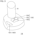
- FIG. 3 is a perspective view showing the structure of the joystick unit 18 by way of example.
- the joystick unit 18 includes the joystick 8, which is tiltable forward, backward, leftward, and rightward (i.e., in all 360-degree directions) from its neutral tilt position, and is rotatable (twistable) leftward and rightward from its neutral twist position about its axis.
- the joystick unit 18 further includes the operation buttons 180.
- the operation buttons 180 includes a joystick button 181 and holding mode setting buttons 182 to 184.
- the joystick button 181 is an operator to be operated by the user to select a control mode (watercraft maneuvering mode) utilizing the joystick 8, i.e., the joystick mode.
- the holding mode setting buttons 182, 183, 184 are operation buttons to be operated by the user to select position/azimuth holding control modes (examples of an automatic watercraft maneuvering mode). More specifically, the holding mode setting button 182 is operated to select a fixed-point holding mode (Stay Point TM ) in which the position and the bow azimuth (or the stern azimuth) of the watercraft 1 are maintained. The holding mode setting button 183 is operated to select a position holding mode (Fish Point TM ) in which the position of the watercraft 1 is maintained but the bow azimuth (or the stern azimuth) of the watercraft 1 is not maintained. The holding mode setting button 184 is operated to select an azimuth holding mode (Drift Point TM ) in which the bow azimuth (or the stern azimuth) of the watercraft 1 is maintained but the position of the watercraft 1 is not maintained.
- a fixed-point holding mode Stay Point TM
- the holding mode setting button 183 is operated to select a position
- the control mode of the main controller 50 can be classified into an ordinary mode, the joystick mode, or the automatic watercraft maneuvering mode in terms of the operation system.
- a steering control operation is performed according to the operation angle signal generated by the steering wheel unit 16, and a propulsive force control operation is performed according to the operation signal (operation position signal) of the remote control lever 7.
- the ordinary mode is a default control mode of the main controller 50.
- the steering control operation specifically, the steering ECU 22 drives the steering actuator 25 according to the operation angle signal generated by the steering wheel unit 16 or the steering angle command generated by the remote control ECU 51.
- the body of the outboard motor OM is steered leftward and rightward such that the propulsive force direction is changed leftward and rightward with respect to the hull 2.
- the engine ECU 21 drives the shift actuator 28 and the throttle actuator 27 according to the propulsive force command (the shift command and the output command) issue from the remote control ECU 51 to the engine ECU 21.
- the shift position of the outboard motor OM is set to the forward shift position, the reverse shift position or the neutral shift position, and the engine output (specifically, the engine speed) of the outboard motor OM is changed.
- the steering control operation and the propulsive force control operation are performed according to the operation signal of the joystick 8 of the joystick unit 18.
- the steering control operation and the propulsive force control operation are performed on the outboard motor OM. That is, the main controller 50 applies the steering angle command and the propulsive force command to the remote control ECU 51, and the remote control ECU 51 applies the steering angle command and the propulsive force command to the steering ECU 22 and the engine ECU 21, respectively.
- the steering control operation and/or the propulsive force control operation are automatically performed by the functions of the main controller 50 and the like without the operation of the steering wheel 6, the remote control lever 7, and the joystick 8. That is, the automatic watercraft maneuvering operation is performed.
- the automatic watercraft maneuvering operation includes an automatic watercraft maneuvering operation to be performed on a sailing basis during sailing, and an automatic watercraft maneuvering operation on a position/azimuth holding basis to maintain one or both of the position and the azimuth. Examples of the automatic watercraft maneuvering operation on the sailing basis include the automatic steering operations to be selected by operating the function switches 61.
- Examples of the automatic watercraft maneuvering operation on the position/azimuth holding basis include watercraft maneuvering operations to be performed in the fixed-point holding mode, the position holding mode, and the azimuth holding mode, which are respectively selected by operating the holding mode setting buttons 182, 183, and 184.
- a cooperative mode in which the outboard motor OM and the bow thruster BT cooperate to achieve an intended hull behavior or a non-cooperative mode in which the outboard motor OM and the bow thruster BT do not cooperate is selectable in the joystick mode and the automatic watercraft maneuvering mode.
- a selection operator to be operated by the user to select the cooperative mode or the non-cooperative mode may be assigned to any of the function switches 61 provided on the application switch panel 60.
- the selection of the cooperative mode or the non-cooperative mode may be achieved by operating the input device 10 of the gauge 9.
- the main controller 50 performs the steering control operation and the propulsive force control operation on the outboard motor OM and, in addition, performs the propulsive force control operation on the bow thruster BT.
- FIGS. 4 and 5 are diagrams for describing the joystick mode in the cooperative mode, showing the operation states of the joystick 8 and the corresponding behaviors of the hull 2.
- the main controller 50 includes a plurality of sub-modes (control modes) including a neutral mode in which no propulsive force is applied to the hull 2, a bow turning mode in which the bow of the hull 2 is turned, and an anteroposterior mode in which the hull 2 is anteroposteriorly moved.
- the main controller 50 is in the neutral mode.
- the main controller 50 controls the propulsive force of the bow thruster BT to zero, sets the shift position of the outboard motor OM to the neutral shift position N, and controls the steering angle of the outboard motor OM to zero.
- the main controller 50 is switched from the neutral mode to the anteroposterior mode. This operation is shown in FIG. 4 .
- the main controller 50 is switched from the neutral mode to the bow turning mode. This operation is shown in FIG. 5 .
- the main controller 50 is switched into the anteroposterior mode when the joystick 8 is operated anteroposteriorly in the neutral mode.
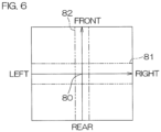
- the main controller 50 determines that the joystick 8 is operated anteroposteriorly, if the anteroposterior component of the tilt amount of the joystick 8 from the neutral tilt position 80 (see FIG. 6 ) (hereinafter referred to simply as "tilt amount") falls outside a predetermined anteroposterior insensitive zone 81 (see FIG. 6 ).
- tilt amount the anteroposterior component of the tilt amount of the joystick 8 from the neutral tilt position 80 (see FIG. 6 ) (hereinafter referred to simply as "tilt amount" falls outside a predetermined anteroposterior insensitive zone 81 (see FIG. 6 ).
- the main controller 50 determines that the joystick 8 is operated laterally if the lateral component of the tilt amount of the joystick 8 falls outside a lateral insensitive zone 82 (see FIG. 6 ).
- the main controller 50 causes the bow thruster BT to generate the propulsive force according to the lateral component of the tilt amount of the joystick 8. Further, the main controller 50 causes the outboard motor OM to generate the propulsive force according to the anteroposterior component of the tilt amount of the joystick 8. Further, the main controller 50 controls the steering angle of the outboard motor OM by controlling the steering actuator 25 according to the twisting of the joystick 8 to drive the steering mechanism 26.
- the main controller 50 controls the propulsive force of the bow thruster BT to zero, sets the shift position of the outboard motor OM to the forward shift position F, controls the magnitude of the propulsive force of the outboard motor OM according to the tilt amount of the joystick 8, and controls the steering angle of the outboard motor OM to zero. If the joystick 8 is thereafter twisted, the main controller 50 steers the outboard motor OM so as to promote the bow turning of the hull 2 in a direction corresponding to the twisting direction (rotating direction) of the joystick 8.
- the steering direction of the outboard motor OM corresponds to the twisting direction of the joystick 8
- the steering amount of the outboard motor OM corresponds to the twisting amount (rotating amount) of the joystick 8.
- the twisting amount is a twisting amount from the neutral twist position of the joystick 8 (this definition also applies to the following description).
- the propulsive force of the bow thruster BT is kept at zero.
- the user is able to adjust the steering of the outboard motor OM by the twisting of the joystick 8, while adjusting the propulsive force of the outboard motor OM by the forward tilt amount of the joystick 8.
- the main controller 50 causes the bow thruster BT to generate a rightward propulsive force, and controls the magnitude of the rightward propulsive force according to the lateral component of the tilt amount of the joystick 8. Further, the main controller 50 sets the shift position of the outboard motor OM to the forward shift position F, controls the magnitude of the propulsive force of the outboard motor OM according to the anteroposterior component of the tilt amount of the joystick 8, and controls the steering angle of the outboard motor OM to zero.
- the main controller 50 steers the outboard motor OM so as to promote the bow turning of the hull 2 in a direction corresponding to the twisting direction of the joystick 8. That is, the steering direction of the outboard motor OM corresponds to the twisting direction of the joystick 8, and the steering amount of the outboard motor OM corresponds to the twisting amount of the joystick 8.
- the rightward propulsive force generated by the bow thruster BT applies a clockwise bow turning moment to the hull 2.
- the outboard motor OM is steered leftward with respect to its neutral steering position (a position at which the steering angle is zero), and the propulsive force of the outboard motor OM applies a counterclockwise bow turning moment to the hull 2.
- the clockwise bow turning moment issued by the propulsive force of the bow thruster BT is reduced.
- the outboard motor OM is steered rightward with respect to the neutral steering position, and the propulsive force of the outboard motor OM applies a clockwise bow turning moment to the hull 2.
- the clockwise bow turning moment is added to the clockwise bow turning moment issued by the propulsive force of the bow thruster BT.
- the user is able to move the hull 2 in the diagonally forward-right direction by the tilting of the joystick 8, and is able to adjust the bow turning of the hull 2 by the twisting of the joystick 8.
- the user is able to find a twist position of the joystick 8 at which the hull 2 is free from the bow turning, while operating the joystick 8, to thus cause the hull 2 to translate in the diagonally forward-right direction.
- the main controller 50 causes the bow thruster BT to generate a leftward propulsive force, and controls the magnitude of the leftward propulsive force according to the lateral component of the tilt amount of the joystick 8. Further, the main controller 50 sets the shift position of the outboard motor OM to the forward shift position F, controls the magnitude of the propulsive force of the outboard motor OM according to the anteroposterior component of the tilt amount of the joystick 8, and controls the steering angle of the outboard motor OM to zero.
- the main controller 50 steers the outboard motor OM so as to promote the bow turning of the hull 2 in a direction corresponding to the twisting direction of the joystick 8. That is, the steering direction of the outboard motor OM corresponds to the twisting direction of the joystick 8, and the steering amount of the outboard motor OM corresponds to the twisting amount of the joystick 8.
- the leftward propulsive force generated by the bow thruster BT applies a counterclockwise bow turning moment to the hull 2.
- the outboard motor OM is steered rightward with respect to the neutral steering position, and the propulsive force of the outboard motor OM applies a clockwise bow turning moment to the hull 2.
- the counterclockwise bow turning moment issued by the propulsive force of the bow thruster BT is reduced.
- the outboard motor OM is steered leftward with respect to the neutral steering position, and the propulsive force of the outboard motor OM applies a counterclockwise bow turning moment to the hull 2.
- the counterclockwise bow turning moment is added to the counterclockwise bow turning moment issued by the propulsive force of the bow thruster BT.
- the user is able to move the hull 2 in the diagonally forward-left direction by the tilting of the joystick 8, and is able to adjust the bow turning of the hull 2 by the twisting of the joystick 8.
- the user is able to find a twist position of the joystick 8 at which the hull 2 is free from the bow turning, while operating the joystick 8, to thus cause the hull 2 to translate in the diagonally forward-left direction.
- the main controller 50 controls the propulsive force of the bow thruster BT to zero, sets the shift position of the outboard motor OM to the reverse shift position R, controls the magnitude of the propulsive force of the outboard motor OM according to the tilt amount of the joystick 8, and controls the steering angle of the outboard motor OM to zero. If the joystick 8 is thereafter twisted, the main controller 50 steers the outboard motor OM so as to promote the bow turning of the hull 2 in a direction corresponding to the twisting direction of the joystick 8.
- the steering direction of the outboard motor OM corresponds to a direction opposite to the twisting direction of the joystick 8
- the steering amount of the outboard motor OM corresponds to the twisting amount of the joystick 8.
- the propulsive force of the bow thruster BT is kept at zero.
- the user is able to adjust the steering of the outboard motor OM by the twisting of the joystick 8 while adjusting the propulsive force of the outboard motor OM by the rearward tilt amount of the joystick 8.
- the main controller 50 causes the bow thruster BT to generate a rightward propulsive force, and controls the magnitude of the rightward propulsive force according to the lateral component of the tilt amount of the joystick 8. Further, the main controller 50 sets the shift position of the outboard motor OM to the reverse shift position R, controls the magnitude of the propulsive force of the outboard motor OM according to the anteroposterior component of the tilt amount of the joystick 8, and controls the steering angle of the outboard motor OM to zero.
- the main controller 50 steers the outboard motor OM so as to promote the bow turning of the hull 2 in a direction corresponding to the twisting direction of the joystick 8. That is, the steering direction of the outboard motor OM corresponds to a direction opposite to the twisting direction of the joystick 8, and the steering amount of the outboard motor OM corresponds to the twisting amount of the joystick 8.
- the rightward propulsive force generated by the bow thruster BT applies a clockwise bow turning moment to the hull 2.
- the user is able to move the hull 2 in the diagonally rearward-right direction by the tilting of the joystick 8, and is able to adjust the bow turning of the hull 2 by the twisting of the joystick 8.
- the user is able to find a twist position of the joystick 8 at which the hull 2 is free from the bow turning, while operating the joystick 8, to thus cause the hull 2 to translate in the diagonally rearward-right direction.
- the main controller 50 causes the bow thruster BT to generate a leftward propulsive force, and controls the magnitude of the leftward propulsive force according to the lateral component of the tilt amount of the joystick 8. Further, the main controller 50 sets the shift position of the outboard motor OM to the reverse shift position R, controls the magnitude of the propulsive force of the outboard motor OM according to the anteroposterior component of the tilt amount of the joystick 8, and controls the steering angle of the outboard motor OM to zero.
- the main controller 50 steers the outboard motor OM so as to promote the bow turning of the hull 2 in a direction corresponding to the twisting direction of the joystick 8. That is, the steering direction of the outboard motor OM corresponds to a direction opposite to the twisting direction of the joystick 8, and the steering amount of the outboard motor OM corresponds to the twisting amount of the joystick 8.
- the leftward propulsive force generated by the bow thruster BT applies a counterclockwise bow turning moment to the hull 2.
- the user is able to move the hull 2 in the diagonally rearward-left direction by the tilt of the joystick 8, and is able to adjust the bow turning of the hull 2 by the twisting of the joystick 8.
- the user is able to find a twist position of the joystick 8 at which the hull 2 is free from the bow turning, while operating the joystick 8, to thus cause the hull 2 to translate in the diagonally rearward-left direction.
- the main controller 50 maintains the neutral mode, and the propulsive forces of the bow thruster BT and the outboard motor OM are controlled to zero. That is, the bow thruster BT is not driven, and the shift position of the outboard motor OM is set to the neutral shift position N.
- the main controller 50 determines that the joystick 8 is in the neutral tilt position.
- the twisting amount of the joystick 8 falls within a predetermined rotation insensitive zone
- the main controller 50 determines that the joystick 8 is in the neutral twist position.
- the main controller 50 is in the neutral mode. Even if the joystick 8 is tilted laterally from the neutral tilt position over the lateral insensitive zone 82 (see FIG. 6 ) in the neutral mode when the anteroposterior component of the tilt amount of the joystick 8 falls within the anteroposterior insensitive zone 81 (see FIG. 6 ), the main controller 50 maintains the neutral mode.
- the main controller 50 is switched to the bow turning mode when the joystick 8 is twisted (rotated) in the neutral mode.
- the main controller 50 causes the bow thruster BT to generate a propulsive force according to the twisting of the joystick 8. Further, the main controller 50 steers the outboard motor OM according to the twisting of the joystick 8, and causes the outboard motor OM to generate a propulsive force according to the anteroposterior component of the tilt amount of the joystick 8.
- the main controller 50 drives the bow thruster BT so as to promote the bow turning of the hull 2 in a direction corresponding to the twisting direction of the joystick 8. That is, if the joystick 8 is twisted clockwise from the neutral twist position, the main controller 50 causes the bow thruster BT to generate a rightward propulsive force, and controls the magnitude of the rightward propulsive force according to the twisting amount of the joystick 8 from the neutral twist position. Thus, a clockwise bow turning moment is applied to the hull 2.
- the main controller 50 causes the bow thruster BT to generate a leftward propulsive force, and controls the magnitude of the leftward propulsive force according to the twisting amount of the joystick 8 from the neutral twist position.
- a counterclockwise bow turning moment is applied to the hull 2.
- the main controller 50 sets the shift position of the outboard motor OM to the neutral shift position N so as to prevent the outboard motor OM from generating the propulsive force.
- the main controller 50 may control the steering angle of the outboard motor OM according to the twisting of the joystick 8. This steering angle control may be performed in substantially the same manner as when the joystick 8 is tilted forward in the anteroposterior mode.
- the main controller 50 sets the shift position of the outboard motor OM to the forward shift position F, and causes the outboard motor OM to generate a propulsive force having a magnitude corresponding to the anteroposterior component of the tilt amount of the joystick 8.
- the main controller 50 steers the outboard motor OM in a direction corresponding to the twisting of the joystick 8, i.e., steers the outboard motor OM rightward with respect to the neutral steering position.
- the steering amount of the outboard motor OM corresponds to the twisting amount of the joystick 8 from the neutral twist position.
- the main controller 50 sets the shift position of the outboard motor OM to the reverse shift position R, and causes the outboard motor OM to generate a propulsive force having a magnitude corresponding to the anteroposterior component of the tilt amount of the joystick 8.
- the main controller 50 steers the outboard motor OM in a direction opposite to the twisting direction of the joystick 8, i.e., steers the outboard motor OM leftward with respect to the neutral steering position.
- the steering amount of the outboard motor OM corresponds to the twisting amount of the joystick 8 from the neutral twist position.
- the main controller 50 sets the shift position of the outboard motor OM to the forward shift position F, and causes the outboard motor OM to generate a propulsive force having a magnitude corresponding to the anteroposterior component of the tilt amount of the joystick 8.
- the main controller 50 steers the outboard motor OM in a direction corresponding to the twisting of the joystick 8, i.e., steers the outboard motor OM leftward with respect to the neutral steering position.
- the steering amount of the outboard motor OM corresponds to the twisting amount of the joystick 8 from the neutral twist position.
- the main controller 50 sets the shift position of the outboard motor OM to the reverse shift position R, and causes the outboard motor OM to generate a propulsive force having a magnitude corresponding to the anteroposterior component of the tilt amount of the joystick 8.
- the main controller 50 steers the outboard motor OM in a direction opposite to the twisting direction of the joystick 8, i.e., steers the outboard motor OM rightward with respect to the neutral steering position.
- the steering amount of the outboard motor OM corresponds to the twisting amount of the joystick 8 from the neutral twist position.
- the main controller 50 is switched into the anteroposterior mode.
- the steering control operation is performed on the outboard motor OM according to the twisting of the joystick 8 as in the anteroposterior mode.
- FIG. 7 is a diagram for describing the characteristic features of an azimuth holding control to be performed by the watercraft propulsion system 100, showing the operation states of the joystick 8 and the corresponding behaviors of the hull 2 by way of example.
- the joystick unit 18 is an example of the traveling direction command generator that gives a traveling direction command to indicate the traveling direction of the hull 2 by the tilt direction of the joystick 8. Further, the joystick unit 18 also serves as an exemplary propulsive force command generator that generates the propulsive force command according to the tilt amount of the joystick 8. Further, the joystick unit 18 is an example of the twist operator or a tilt/twist operator that generates a bow turning command to indicate the bow turning of the hull 2 according to the turning (twisting) of the joystick 8 .
- an anteroposterior direction command is issue from the joystick unit 18 to indicate a traveling direction parallel to the anteroposterior direction of the hull 2
- the main controller 50 performs an azimuth holding control to maintain the azimuth of the hull 2 by controlling the bow thruster BT.
- the main controller 50 regards the output of the joystick unit 18 as the anteroposterior direction command. That is, the anteroposterior direction command is issued to the main controller 50 by tilting the joystick 8 straight forward or straight rearward.
- the main controller 50 When the bow turning command is inputted from the joystick unit 18, the main controller 50 does not perform the azimuth holding control. When the twisting amount of the joystick 8 from the neutral twist position falls within the rotation insensitive zone, the main controller 50 determines that the bow turning command is not issued. When the twisting amount of the joystick 8 from the neutral twist position falls outside the rotation insensitive zone, the main controller 50 determines that the bow turning command is inputted. Thus, the azimuth holding control is effected by tilting the joystick 8 straight forward or straight rearward without twisting the joystick 8.
- an anteroposterior direction command is issued to the main controller 50 to indicate straight forward movement.
- the main controller 50 applies a propulsive force command and a steering angle command to the outboard motor OM for the straight forward movement.
- the shift position of the outboard motor OM is set to the forward shift position F, and the output of the engine 23 (engine speed) is controlled according to the anteroposterior component of the tilt amount of the joystick 8.
- the steering angle of the outboard motor OM is controlled to zero (neutral tilt position).
- the main controller 50 sets a target azimuth by acquiring an output of the azimuth sensor 53 observed when the anteroposterior direction command is issued, and performs the azimuth holding control to maintain the hull azimuth at the target azimuth (reference character A2). That is, the main controller 50 applies a propulsive force command to the bow thruster BT so as to eliminate a deviation of a hull azimuth thereafter detected by the azimuth sensor 53 from the target azimuth (azimuth deviation). This makes it possible to move the hull 2 straight while maintaining the hull azimuth by utilizing the propulsive force of the bow thruster BT. That is, even if the hull azimuth is deviated due to an external disturbance 70, the azimuth deviation is automatically eliminated without the need for the user to perform an azimuth deviation eliminating operation.
- the main controller 50 performs a control operation to turn the hull 2. That is, the main controller 50 applies a steering angle command to the outboard motor OM based on a bow turning command issued thereto by the twisting of the joystick 8.
- the outboard motor OM is steered to apply a bow turning moment to the hull 2 such that the hull 2 is moved forward while being turned (reference character A4).
- the bow turning command is inputted to the main controller 50 by the twisting of the joystick 8, so that the main controller 50 stops the azimuth holding control.
- the user stops twisting the joystick 8 (reference character A5).
- the twisting amount of the joystick 8 thus falls within the rotation insensitive zone, the bow turning command is no longer inputted and, therefore, the main controller 50 starts the azimuth holding control (reference character A6).
- the azimuth holding control is performed by utilizing the propulsive force of the bow thruster BT.
- the joystick 8 When the user stops tilting the joystick 8, the joystick 8 is returned into the neutral tilt position. That is, the anteroposterior component of the tilt amount of the joystick 8 falls within the anteroposterior insensitive zone 81 (see FIG. 6 ), so that the anteroposterior direction command is no longer inputted to the main controller 50 (reference character A7).
- the main controller 50 generates a propulsive force command to stop the output of the propulsive force of the outboard motor OM.
- the shift position of the outboard motor OM is set to the neutral shift position N so that the outboard motor OM no longer outputs the propulsive force.
- the hull 2 is moved in the previous traveling direction due to inertia.
- the main controller 50 continues the azimuth holding control for a predetermined period (e.g., 10 seconds) (reference character A8), and then stops the azimuth holding control after a lapse of the predetermined period. Since the hull azimuth is thus maintained even during the inertial movement of the hull 2, the user does not need to perform an azimuth correcting operation.
- a predetermined period e.g. 10 seconds
- the main controller 50 starts measuring the predetermined period. If the anteroposterior direction command is issued again before the measurement of the predetermined period ends (reference character A9), however, the main controller 50 cancels the measurement of the period. Thus, the azimuth holding control is restarted, so that the period of the azimuth holding control is practically extended (reference character A10).
- the previous target azimuth may be used as it is. Alternatively, the target azimuth may be newly set based on a signal outputted by the azimuth sensor 53 when the azimuth holding control is restarted. Even in this case, substantially the same target azimuth as the previous target azimuth is set for the azimuth holding control to be continuously performed.
- FIGS. 8A and 8B are flowcharts for an exemplary process to be performed by the main controller 50 in response to the anteroposterior direction command.
- the main controller 50 determines whether or not at least one of the following preconditions is satisfied (preferably, whether or not all the following preconditions are satisfied): a precondition that the main controller 50 is in the cooperative mode; a precondition that no error occurs in the azimuth sensor 53; and a precondition that the azimuth holding control function is effected (e.g., by operating the input device 10 of the gauge 9) when the hull 2 is moved in the anteroposterior direction (Step S1). If the preconditions are satisfied (NO in Step S1), the process ends.
- Step S2 If the anteroposterior direction command is inputted (YES in Step S2) when the preconditions are satisfied (YES in Step S1), the main controller 50 is switched into the anteroposterior mode (Step S3), and then determines whether or not the bow turning command is inputted (Step S7) and whether or not the yaw rate of the hull 2 is equal to or less than a predetermined threshold for longer than a predetermined period (Step S8). If the twisting amount of the joystick 8 falls within the rotation insensitive zone, the main controller 50 determines that the bow turning command is not inputted. If the twisting amount of the joystick 8 falls outside the rotation insensitive zone, the main controller 50 determines that the bow turning command is inputted.
- the yaw rate of the hull 2 may be determined, for example, by time-differentiating the azimuth detected by the azimuth sensor 53.
- the main controller 50 determines that a trigger condition for the start of the azimuth holding control is satisfied. If the trigger condition is satisfied, the main controller 50 sets a hull azimuth outputted at this time by the azimuth sensor 53 as the target azimuth (Step S9), and controls the bow thruster BT for the azimuth holding control (Step S10).
- Step S18 the main controller 50 checks whether or not its timer currently measures the predetermined period (e.g., 10 seconds) (Step S18). If the timer does not currently measure the period, the main controller 50 starts the timer (Step S19). If the timer currently measures the period (YES in Step S18), the main controller 50 checks whether or not the timer ends the measurement of the predetermined period (Step S20).
- the predetermined period e.g. 10 seconds
- Step S19 When the timer is started (Step S19) or when the timer currently measures the predetermined period (NO in Step S20), a process sequence from Step S10 is performed. In these cases, the main controller 50 determines that a continuation condition for the continuation of the azimuth holding control is satisfied, and continuously performs the azimuth holding control by still using the previous target azimuth (Step S10).
- Step S21 If the predetermined period is elapsed after the main controller 50 is switched into the neutral mode with the anteroposterior direction command no longer inputted (YES in Step S20), the main controller 50 determines that a cancellation condition for the cancellation of the azimuth holding control is satisfied, and stops the azimuth holding control (Step S21).
- Step S2 If the anteroposterior direction command is inputted again (YES in Step S2) when the timer continues the measurement of the predetermined period, i.e., when the azimuth holding control continues after the anteroposterior direction command is no longer inputted, the main controller 50 is switched from the neutral mode into the anteroposterior mode (Step S3). At this time, because the timer continues the measurement of the predetermined period (YES in Step S4), the main controller 50 stops and resets the timer to cancel the measurement of the predetermined period (Step S5). The main controller 50 does not count up the timer until the main controller 50 is thereafter switched again into the neutral mode.
- the previous target azimuth is still used (YES in Step S6), and the azimuth holding control is continued (Step S10).
- the target azimuth may be newly set, and the azimuth holding control may be started based on the new target azimuth.
- the timer may be reset immediately before the start of the timer (Step S19).
- Step S7 If the bow turning command is inputted (YES in Step S7) or if the yaw rate of the hull 2 is greater than the predetermined threshold for longer than the predetermined period (NO in Step S8), the main controller 50 does not start the azimuth holding control. Further, if the yaw rate of the hull 2 is equal to or greater than a predetermined threshold for longer than a predetermined period (YES in Step S11, S16) during the azimuth holding control (YES in Step S6, S14), the main controller 50 determines that the cancellation condition is satisfied, and stops the azimuth holding control (Step S21).
- the main controller 50 determines that the cancellation condition is satisfied, and stops the azimuth holding control (Step S21).
- Step S21 when a command indicating a traveling direction nonparallel to the anteroposterior direction of the hull 2 is issued by the operation of the joystick 8 (NO in Step S2, NO in Step S14), the main controller 50 does not start the azimuth holding control. If the command indicating the traveling direction nonparallel to the anteroposterior direction of the hull 2 is given by the operation of the joystick 8 during the azimuth holding control (YES in Step S14, YES in Step S15), the main controller 50 determines that the cancellation condition is satisfied, and stops the azimuth holding control (Step S21).
- the azimuth holding control is performed by utilizing the lateral propulsive force of the bow thruster BT.
- This azimuth holding control is continued even after the anteroposterior direction command is no longer issued with the joystick 8 returned to the neutral tilt position.
- the azimuth of the hull 2 is maintained even during the inertial forward or reverse traveling of the hull 2. This continuously alleviates a burden on the user to perform an operation to correct an unintended change in bow azimuth.
- the azimuth holding control is continued only for the predetermined period and thereafter stopped such that the bow thruster BT is prevented from being continuously driven for a prolonged period longer than necessary.
- the watercraft propulsion system 100 is able to efficiently drive the bow thruster BT to properly perform the azimuth holding operation.
- the efficient driving of the bow thruster BT reduces the power consumption of a battery that supplies electric power to the bow thruster BT, and reduces the heat generated by the electric motor 42 (which is a power source of the bow thruster BT).
- the main controller 50 is configured or programmed to cancel the measurement of the predetermined period to continuously perform the azimuth holding control if the anteroposterior direction command is issued again by the operation of the joystick 8 during the azimuth holding control continued for the predetermined period.
- the azimuth holding control is restarted if the joystick 8 is operated again during the azimuth holding control to issue the anteroposterior direction command after the joystick 8 is returned to the neutral tilt position to nullify the anteroposterior direction command.
- This makes it possible to practically extend the period of the azimuth holding control by the operation of the joystick 8.
- the bow thruster BT is efficiently driven according to the intention of the user to properly perform the azimuth holding operation.
- the main controller 50 is configured or programmed not to start the azimuth holding control, when the bow turning command is inputted from the joystick unit 18 by the twisting of the joystick 8. Further, the main controller 50 is configured or programmed to stop the azimuth holding control if the bow turning command is inputted during the azimuth holding control. Therefore, the azimuth holding control is prevented from interfering with the bow turning command, thus making it possible to perform the watercraft maneuvering operation for the turning of the hull 2 and the fixed-point bow turning of the hull 2 by the twisting of the joystick 8.
- the main controller 50 is configured or programmed not to start the azimuth holding control, when the command indicating the traveling direction nonparallel to the anteroposterior direction of the hull 2 is issued by the operation of the joystick 8. Further, the main controller 50 is configured or programmed to stop the azimuth holding control currently continued if the commend indicating the traveling direction nonparallel to the anteroposterior direction of the hull 2 is issued by the operation of the joystick 8 during the azimuth holding control. This prevents the azimuth holding control from interfering with the movement of the hull 2 (particularly, involving the turning of the hull 2) .
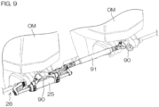
- FIG. 9 is a diagram showing an arrangement of a watercraft propulsion system according to another example embodiment of the present invention.
- the single propulsion device (single outboard motor OM) is provided on the stern of the hull 2 by way of an example.
- the example embodiments described above may be applied to an arrangement which includes a plurality of propulsion devices provided on the stern of the hull 2 and adapted to be steered at the same steering angle.
- FIG. 9 is a diagram showing an arrangement of a watercraft propulsion system according to another example embodiment of the present invention.
- the single propulsion device single outboard motor OM
- the example embodiments described above may be applied to an arrangement which includes a plurality of propulsion devices provided on the stern of the hull 2 and adapted to be steered at the same steering angle.
- the steering levers 90 of the respective outboard motors OM provided on the stern are mechanically connected together by a link 91, and the outboard motors OM (in this example, two outboard motors OM) are steered in synchronism (i.e., at the same steering angle) by a single steering.
- the steering includes a steering actuator 25 and a steering mechanism 26 to be driven by the steering actuator 25.
- the plurality of propulsion devices to be steered in synchronism at the same steering angle apply their propulsive forces in the same direction to the hull 2, but do not apply the propulsive forces simultaneously in different directions to the hull 2.
- a combination of the plurality of propulsion devices is equivalent to the single propulsion device. Therefore, the example embodiments described above are applicable to a watercraft propulsion system which includes a plurality of propulsion devices provided on the stern of a hull 2 and incapable of applying their propulsive forces simultaneously in different directions to the hull 2, and a bow thruster BT provided at the bow of the hull 2.
- the bow thruster BT is fixed to the hull 2 in the unsteerable manner.
- a steerable propulsion unit such as a trolling motor may be used as the bow thruster BT.
- the example embodiments described above are applicable even in this case.
- the example embodiments described above include an exemplary case in which the single propulsion device is provided on the hull, and an exemplary case in which the plurality of propulsion devices to be steered at the same steering angle are provided on the hull.
- the example embodiments may be applied to a watercraft propulsion system including a plurality of propulsion devices provided on the hull and steerable at different steering angles.
- the outboard motor is used as the propulsion device by way of an example, but the propulsion device may be in any of various types such as an inboard motor, an inboard/outboard motor, and a waterjet propulsion device.
- the propulsion device may be provided on a portion of the hull other than the stern.
- the joystick unit 18 doubles as the twist operator by way of example, but a twist operator 15 separate from the joystick unit may be provided as shown in Fig. 1 . Further, a traveling direction command generator other than the joystick unit may be used.
Landscapes
- Chemical & Material Sciences (AREA)
- Engineering & Computer Science (AREA)
- Combustion & Propulsion (AREA)
- Mechanical Engineering (AREA)
- Ocean & Marine Engineering (AREA)
- Mechanical Control Devices (AREA)
- Control Of Position, Course, Altitude, Or Attitude Of Moving Bodies (AREA)
Abstract
Description
- The present invention relates to watercraft propulsion systems, and watercraft including the watercraft propulsion systems.
-
JP 3057413 B2 - The inventor of example embodiments of the present invention described and claimed in the present application conducted an extensive study and research regarding a watercraft propulsion system, such as the one described above, and in doing so, discovered and first recognized new unique challenges and previously unrecognized possibilities for improvements as described in greater detail below.
- In the prior art disclosed in
JP 3057413 B2 - Where an electric bow thruster is used, for example, it is preferred to efficiently drive the bow thruster only when necessary in consideration of battery consumption, heat generation due to the continuous operation, and the like. Therefore, the prior art still has room for improvement.
- In view of the foregoing, example embodiments of the present invention provide watercraft propulsion systems that are each able to properly perform an azimuth holding operation by efficiently driving a bow thruster, and watercraft including the watercraft propulsion systems.
- In order to overcome the previously unrecognized and unsolved challenges described above, an example embodiment of the present invention provides a watercraft propulsion system including a bow thruster provided at a bow of a hull to generate a propulsive force laterally of the hull, a propulsion device provided on the hull to generate a propulsive force anteroposteriorly of the hull, and a steering to change the course of the hull. The watercraft propulsion system further includes a joystick to be operated by a user (watercraft operator) to issue a traveling direction command to indicate the traveling direction of the hull, and tiltable from its neutral tilt position in all directions, and a controller configured or programmed to control the bow thruster, the propulsion device, and the steering according to an operation of the joystick. The controller is configured or programmed to perform an azimuth holding control to maintain the azimuth of the hull by controlling the bow thruster if an anteroposterior direction command is issued to indicate a traveling direction parallel to the anteroposterior direction of the hull by the operation of the joystick. The controller is further configured or programmed to stop the azimuth holding control after the azimuth holding control is continued for a predetermined period of time if the anteroposterior direction command is no longer issued with the joystick returned to the neutral tilt position during the azimuth holding control.
- With this arrangement, the azimuth holding control is performed by utilizing the lateral propulsive force of the bow thruster if the anteroposterior direction command is issued to the controller by the operation of the joystick. This alleviates a burden on the user to perform an operation against a change in bow azimuth due to an external disturbance or the like. This azimuth holding control is continued even after the anteroposterior direction command is no longer issued with the joystick returned to the neutral tilt position. Therefore, the azimuth of the hull is maintained even during the inertial forward or reverse traveling of the hull. This continuously alleviates a burden on the user to perform an operation to correct an unintended change in bow azimuth. On the other hand, the azimuth holding control is continued only for the predetermined period of time and thereafter stopped such that the bow thruster is prevented from being continuously driven for a prolonged period of time of time longer than necessary. Thus, the watercraft propulsion system is able to efficiently drive the bow thruster to properly perform the azimuth holding operation.
- The azimuth holding control is typically a control operation to be performed to maintain the azimuth of the hull observed when the azimuth holding control is started.
- In an example embodiment of the present invention, the controller is configured or programmed to cancel a measurement of the predetermined period of time and perform the azimuth holding control if the anteroposterior direction command is issued again by the operation of the joystick during the azimuth holding control continued for the predetermined period of time.
- With this arrangement, the azimuth holding control is restarted, if the anteroposterior direction command is issued again by the operation of the joystick during the azimuth holding control after the joystick is returned to the neutral tilt position to nullify the anteroposterior direction command. This makes it possible to practically extend the period of time of the azimuth holding control by the operation of the joystick. Thus, the bow thruster is efficiently driven according to the intention of the user to properly perform the azimuth holding operation.
- In an example embodiment of the present invention, the watercraft propulsion system further includes a twist operator to be operated by the user to issue a bow turning command to indicate the bow turning of the hull, and that is rotatable leftward and rightward from its neutral twist position. The controller is configured or programmed not to start the azimuth holding control if the bow turning command is inputted from the twist operator, and to stop the azimuth holding control if the bow turning command is inputted from the twist operator during the azimuth holding control.
- With this arrangement, the user is able to turn the bow of the hull by rotating the twist operator leftward and rightward. When the bow turning command is inputted from the twist operator to the controller, the azimuth holding control is not performed. If the bow turning command is inputted to the controller during the azimuth holding control, the azimuth holding control is stopped. Therefore, the azimuth holding control is prevented from interfering with the bow turning command, thus making it possible to efficiently utilize the propulsive force of the bow thruster.
- The joystick may double as the twist operator. That is, the joystick may be configured to be tiltable and rotatable (twistable), and the joystick may be correspondingly configured to output the traveling direction command and the bow turning command.
- In an example embodiment of the present invention, the controller is configured or programmed not to start the azimuth holding control when a command indicating a traveling direction nonparallel to the anteroposterior direction of the hull is issued by the operation of the joystick. Further, the controller is configured or programmed to stop the azimuth holding control if the command indicating the traveling direction nonparallel to the anteroposterior direction of the hull is issued by the operation of the joystick during the azimuth holding control.
- With this arrangement, the azimuth holding control is not performed when the command indicating the traveling direction nonparallel to the anteroposterior direction is issued. Thus, the azimuth holding control is prevented from interfering with the movement of the hull (particularly, involving the turning of the hull). This makes it possible to efficiently utilize the propulsive force of the bow thruster.
- Another example embodiment of the present invention provides a watercraft propulsion system including a bow thruster provided at a bow of a hull to generate a propulsive force laterally of the hull, a traveling direction command generator to be operated by a user (watercraft operator) to issue a traveling direction command to indicate the traveling direction of the hull, and a controller. The controller is configured or programmed to perform an azimuth holding control to maintain the azimuth of the hull by controlling the bow thruster if the traveling direction command generator outputs an anteroposterior direction command to indicate a traveling direction parallel to the anteroposterior direction of the hull, and to stop the azimuth holding control after the azimuth holding control is continued for a predetermined period of time if the anteroposterior direction command is no longer outputted during the azimuth holding control.
- With this arrangement, the azimuth holding control is performed by utilizing the lateral propulsive force of the bow thruster if the anteroposterior direction command is issued to the controller by the operation of the traveling direction command generator. This alleviates a burden on the user to perform an operation against a change in bow azimuth due to an external disturbance or the like. This azimuth holding control is continued even after the anteroposterior direction command is no longer issued. Thus, the azimuth of the hull is maintained even during the inertial forward or reverse traveling of the hull. This continuously alleviates a burden on the user to perform an operation to correct an unintended change in bow azimuth. On the other hand, the azimuth holding control is continued only for the predetermined period of time and thereafter stopped, thus preventing the bow thruster from being continuously driven for a prolonged period of time longer than necessary. Thus, the watercraft propulsion system efficiently drives the bow thruster to properly perform the azimuth holding operation.
- In an example embodiment of the present invention, the bow thruster is fixed to the hull in an unsteerable manner.
- Another further example embodiment of the present invention provides a watercraft including a hull, and a watercraft propulsion system including any of the features described above.
- The above and other elements, features, steps, characteristics and advantages of the present invention will become more apparent from the following detailed description of the example embodiments with reference to the attached drawings.
-
-
FIG. 1 is a plan view showing an exemplary construction of a watercraft mounted with a watercraft propulsion system according to an example embodiment of the present invention. -
FIG. 2 is a block diagram showing a configuration of the watercraft propulsion system by way of an example. -
FIG. 3 is a perspective view showing a structure of a joystick unit by way of an example. -
FIG. 4 is a diagram for describing a neutral mode and an anteroposterior mode, which are sub-modes of a joystick mode. -
FIG. 5 is a diagram for describing the neutral mode and a bow turning mode, which are sub-modes of the joystick mode. -
FIG. 6 is a diagram showing an anteroposterior insensitive zone and a lateral insensitive zone of a joystick. -
FIG. 7 is a diagram for describing the characteristic features of an azimuth holding control to be performed by the watercraft propulsion system, and showing the operation states of the joystick and corresponding hull behaviors by way of example. -
FIG. 8A is a flowchart for an exemplary process to be performed by a main controller in response to an anteroposterior direction command. -
FIG. 8B is a flowchart for the exemplary process to be performed by the main controller in response to the anteroposterior direction command. -
FIG. 9 is a diagram showing an arrangement of a watercraft propulsion system according to another example embodiment of the present invention. -
FIG. 1 is a plan view showing an exemplary construction of awatercraft 1 mounted with awatercraft propulsion system 100 according to an example embodiment of the present invention. Thewatercraft 1 includes ahull 2, a bow thruster BT provided at the bow of thehull 2 to generate a lateral propulsive force, and an outboard motor OM (an example of the propulsion device) provided on the stern 3 of thehull 2 and having a variable steering angle. In the present example embodiment, the single outboard motor OM is provided on acenter line 2a extending anteroposteriorly of thehull 2 by way of an example, but a plurality of outboard motors OM, more specifically, two or more outboard motors OM, may be provided on the stern 3. - The outboard motor OM includes a
propeller 20 located underwater, and is configured to generate a propulsive force by the rotation of thepropeller 20 and apply the propulsive force to thehull 2. The outboard motor OM is attached to the stern 3 pivotably leftward and rightward such that the direction of the propulsive force generated by thepropeller 20 is changed leftward and rightward. The steering angle is defined, for example, as an angle between the direction of the propulsive force generated by thepropeller 20 and an anteroposterior reference direction parallel to thecenter line 2a. The outboard motor OM is configured to be pivoted leftward and rightward by asteering mechanism 26 thereof (seeFIG. 2 ) to thus change the steering angle. When the propulsive force direction is parallel to the anteroposterior direction, the steering angle is zero. When the rear end of the outboard motor OM is directed rightward, the steering angle may be expressed with a positive sign. When the rear end of the outboard motor OM is directed leftward, the steering angle may be expressed with a negative sign. - The bow thruster BT includes a
propeller 40 disposed in atubular tunnel 41 extending through the bow portion of thehull 2 transversely of thehull 2. Thepropeller 40 may include, for example, two propellers connected to the opposite ends of its rotation shaft. Thepropeller 40 is rotatable in a forward rotation direction and a reverse rotation direction, i.e., is bidirectionally rotatable, such that the bow thruster BT is able to apply a rightward or leftward propulsive force to thehull 2. In the present example embodiment, the direction of the propulsive force to be generated by the bow thruster BT is not changeable to a direction other than the rightward direction and the leftward direction. That is, the bow thruster BT is fixed to thehull 2 in an unsteerable manner in the present example embodiment. - A
usable space 4 for passengers is provided inside thehull 2. Ahelm seat 5 is provided in theusable space 4. Asteering wheel 6, aremote control lever 7, ajoystick 8, a gauge 9 (display panel) and the like are provided in association with thehelm seat 5. Thesteering wheel 6 is an operator to be operated by a user (watercraft operator) to change the course of thewatercraft 1. Theremote control lever 7 is an operator to be operated by the user to change the magnitude (output) and the direction (a forward or reverse direction) of the propulsive force of the outboard motor OM, and corresponds to an acceleration operator. Thejoystick 8 is an operator to be operated instead of thesteering wheel 6 and theremote control lever 7 by the user for watercraft maneuvering. An operator 45 (seeFIG. 2 ) dedicated for the operation of the bow thruster BT may be provided in addition to the aforementioned operators. -
FIG. 2 is a block diagram showing the configuration of thewatercraft propulsion system 100 provided in thewatercraft 1 by way of an example. Thewatercraft propulsion system 100 includes the outboard motor OM and the bow thruster BT. The outboard motor OM may be an engine outboard motor or an electric outboard motor. InFIG. 2 , the engine outboard motor is illustrated as the outboard motor OM by way of an example. - The outboard motor OM includes an engine ECU (Electronic Control Unit) 21, a
steering ECU 22, anengine 23, ashift mechanism 24, thepropeller 20, thesteering mechanism 26 and the like. Power generated by theengine 23 is transmitted to thepropeller 20 via theshift mechanism 24. Thesteering mechanism 26 is configured to pivot the body of the outboard motor OM leftward and rightward with respect to the hull 2 (seeFIG. 1 ) to change the direction of the propulsive force generated by the outboard motor OM leftward and rightward. Theshift mechanism 24 is configured to select a shift position from a forward shift position, a reverse shift position, and a neutral shift position. With the shift position set to the forward shift position, thepropeller 20 is rotated in a forward rotation direction by the transmission of the rotation of theengine 23 such that the outboard motor OM is brought into a forward drive state to generate a forward propulsive force. With the shift position set to the reverse shift position, thepropeller 20 is rotated in a reverse rotation direction by the transmission of the rotation of theengine 23 such that the outboard motor OM is brought into a reverse drive state to generate a reverse propulsive force. With the shift position set to the neutral shift position, the power transmission between theengine 23 and thepropeller 20 is interrupted such that the outboard motor OM is brought into an idling state. - The outboard motor OM further includes a
throttle actuator 27 and ashift actuator 28, which are controlled by theengine ECU 21. Thethrottle actuator 27 is an electric actuator (typically including an electric motor) that actuates the throttle valve (not shown) of theengine 23. Theshift actuator 28 is an actuator that actuates theshift mechanism 24. The outboard motor OM further includes asteering actuator 25 to be controlled by the steeringECU 22. The steeringactuator 25 is the drive source of thesteering mechanism 26, and typically includes an electric motor. The steeringactuator 25 may include a hydraulic device of an electric pump type. The steeringactuator 25 and thesteering mechanism 26 are a nonlimiting example of the steering that changes the course of thehull 2. - The bow thruster BT includes the
propeller 40, anelectric motor 42 that drives thepropeller 40, and amotor controller 43 that controls theelectric motor 42. - The
watercraft propulsion system 100 further includes amain controller 50. Themain controller 50 includes aprocessor 50a and amemory 50b, and is configured so that theprocessor 50a executes a program stored in thememory 50b to perform a plurality of functions. Themain controller 50 is connected to an onboard network 55 (CAN: Control Area Network) provided in thehull 2. Aremote control unit 17, aremote control ECU 51, ajoystick unit 18, a GPS (Global Positioning System)receiver 52, anazimuth sensor 53 and the like are connected to theonboard network 55. - The
remote control ECU 51 for the outboard motor OM is connected to theonboard network 55. Theengine ECU 21 and thesteering ECU 22 of the outboard motor OM are connected to theremote control ECU 51 via an outboardmotor control network 56. Themain controller 50 transmits and receives signals to/from various units connected to theonboard network 55 to control the outboard motor OM and the bow thruster BT, and further controls other units. Themain controller 50 includes a plurality of control modes, and controls the units in predetermined manners according to the respective control modes. - A
steering wheel unit 16 is connected to the outboardmotor control network 56. Thesteering wheel unit 16 outputs an operation angle signal indicating the operation angle of thesteering wheel 6 to the outboardmotor control network 56. The operation angle signal is received by theremote control ECU 51 and thesteering ECU 22. In response to the operation angle signal generated by thesteering wheel unit 16 or a steering angle command generated by theremote control ECU 51, the steeringECU 22 correspondingly controls thesteering actuator 25 to thus control the steering angle of the outboard motor OM. - The
remote control unit 17 generates an operation position signal indicating the operation position of theremote control lever 7. - The
joystick unit 18 generates an operation position signal indicating the operation position of thejoystick 8, and generates an operation signal indicating the operation of any ofoperation buttons 180 provided in thejoystick unit 18. - The
remote control ECU 51 outputs a propulsive force command to theengine ECU 21 via the outboardmotor control network 56. The propulsive force command includes a shift command indicating the shift position, and an output command indicating an engine output (specifically, an engine speed). Further, theremote control ECU 51 outputs the steering angle command to thesteering ECU 22 via the outboardmotor control network 56. The steeringECU 22 receives the detection signal of a steering angle sensor (not shown) that detects the steering angle of thesteering mechanism 26. The steeringECU 22 controls thesteering actuator 25 so that the actual steering angle detected by the steering angle sensor matches with the steering angle command issue from theremote control ECU 51. The actual steering angle detected by the steering angle sensor is transmitted to theremote control ECU 51 from the steeringECU 22, and further transmitted to themain controller 50 from theremote control ECU 51. - The
remote control ECU 51 performs different control operations according to different control modes of themain controller 50. In a control mode for watercraft maneuvering with the use of thesteering wheel 6 and theremote control lever 7, for example, theremote control ECU 51 generates the propulsive force command (the shift command and the output command) according to the operation position signal generated by theremote control unit 17, and applies the propulsive force command (the shift command and the output command) to theengine ECU 21. Further, theremote control ECU 51 commands the steeringECU 22 to conform to the operation angle signal generated by thesteering wheel unit 16. In a control mode for watercraft maneuvering without the use of thesteering wheel 6 and theremote control lever 7, on the other hand, theremote control ECU 51 conforms to commands issued by themain controller 50. That is, themain controller 50 generates the propulsive force command (the shift command and the output command) and the steering angle command, and theremote control ECU 51 outputs the propulsive force command (the shift command and the output command) and the steering angle command to theengine ECU 21 and thesteering ECU 22, respectively. In a control mode for watercraft maneuvering with the use of the joystick 8 (joystick mode), for example, themain controller 50 generates the propulsive force command (the shift command and the output command) and the steering angle command according to the signals generated by thejoystick unit 18. The magnitude and the direction (the forward direction or the reverse direction) of the propulsive force and the steering angle of the outboard motor OM are controlled according to the propulsive force command (the shift command and the output command) and the steering angle command thus generated. - The
engine ECU 21 drives theshift actuator 28 according to the shift command to control the shift position, and drives thethrottle actuator 27 according to the output command to control the throttle opening degree of theengine 23. The steeringECU 22 controls thesteering actuator 25 according to the steering angle command to control the steering angle of the outboard motor OM. - The
motor controller 43 of the bow thruster BT is connected to theonboard network 55, and is configured to actuate theelectric motor 42 in response to a command issue from themain controller 50. Themotor controller 43 may be connected to theonboard network 55 via a gateway (not shown). Themain controller 50 issues a propulsive force command to themotor controller 43. The propulsive force command includes a shift command (rotation direction command) and an output command (rotation speed command). The shift command is a rotation direction command that indicates the stop, the forward rotation, or the reverse rotation of thepropeller 40. The output command is a rotation speed command that indicates a propulsive force to be generated, specifically, a target rotation speed value. Themotor controller 43 controls the rotation direction and the rotation speed of theelectric motor 42 according to the shift command (rotation direction command) and the output command. - In this example, the
operator 45 dedicated for the bow thruster BT is connected to themotor controller 43. The user is able to adjust the rotation direction and the rotation speed of the bow thruster BT by operating theoperator 45. - The
GPS receiver 52 is an exemplary position detection device. TheGPS receiver 52 detects the position of thewatercraft 1 by receiving radio waves from an artificial satellite orbiting the earth, and outputs position data indicating the position of thewatercraft 1 and speed data indicating the moving speed of thewatercraft 1. Themain controller 50 acquires the position data and the speed data, which are used to control and display the position and/or the azimuth of thewatercraft 1. GPS is a specific example of GNSS (Global Navigation Satellite System). - The
azimuth sensor 53 detects the azimuth of thewatercraft 1 to generate azimuth data, which is used by themain controller 50. - The
gauge 9 is connected to theonboard network 55. Thegauge 9 is a display device that displays various information for the watercraft maneuvering. Thegauge 9 is able to communicate, for example, with themain controller 50, theremote control ECU 51, and themotor controller 43. Thus, thegauge 9 is able to display the operation state of the outboard motor OM, the operation state of the bow thruster BT, the position and/or the azimuth of thewatercraft 1, and other information. Thegauge 9 may include aninput device 10 such as a touch panel and buttons. Theinput device 10 may be operated by the user to set various settings and give various commands such that operation signals are outputted to theonboard network 55. An additional network other than theonboard network 55 may be provided to transmit display control signals related to thegauge 9. - Further, an
application switch panel 60 is connected to theonboard network 55. Theapplication switch panel 60 includes a plurality of function switches 61 to be operated to issue predefined function commands. For example, the function switches 61 may include switches for automatic watercraft maneuvering commands. More specifically, a command for a bow holding mode (Heading Hold) in which an automatic steering operation is performed to maintain the bow azimuth during forward sailing may be assigned to one of the function switches 61, and a command for a straight sailing holding mode (Course Hold) in which an automatic steering operation is performed to maintain the bow azimuth and a straight course during forward sailing may be assigned to another of the function switches 61. Further, a command for a checkpoint following mode (Track Point™) in which an automatic steering operation is performed to follow a course (route) passing through specified checkpoints may be assigned to further another of the function switches 61, and a command for a pattern sailing mode (Pattern Steer) in which an automatic steering operation is performed to follow a predetermined sailing pattern (zig-zag pattern, spiral pattern or the like) may be assigned to still another of the function switches 61. -
FIG. 3 is a perspective view showing the structure of thejoystick unit 18 by way of example. Thejoystick unit 18 includes thejoystick 8, which is tiltable forward, backward, leftward, and rightward (i.e., in all 360-degree directions) from its neutral tilt position, and is rotatable (twistable) leftward and rightward from its neutral twist position about its axis. In this example, thejoystick unit 18 further includes theoperation buttons 180. Theoperation buttons 180 includes ajoystick button 181 and holdingmode setting buttons 182 to 184. - The
joystick button 181 is an operator to be operated by the user to select a control mode (watercraft maneuvering mode) utilizing thejoystick 8, i.e., the joystick mode. - The holding
mode setting buttons mode setting button 182 is operated to select a fixed-point holding mode (Stay Point™) in which the position and the bow azimuth (or the stern azimuth) of thewatercraft 1 are maintained. The holdingmode setting button 183 is operated to select a position holding mode (Fish Point™) in which the position of thewatercraft 1 is maintained but the bow azimuth (or the stern azimuth) of thewatercraft 1 is not maintained. The holdingmode setting button 184 is operated to select an azimuth holding mode (Drift Point™) in which the bow azimuth (or the stern azimuth) of thewatercraft 1 is maintained but the position of thewatercraft 1 is not maintained. - The control mode of the
main controller 50 can be classified into an ordinary mode, the joystick mode, or the automatic watercraft maneuvering mode in terms of the operation system. - In the ordinary mode, a steering control operation is performed according to the operation angle signal generated by the
steering wheel unit 16, and a propulsive force control operation is performed according to the operation signal (operation position signal) of theremote control lever 7. In the present example embodiment, the ordinary mode is a default control mode of themain controller 50. In the steering control operation, specifically, the steeringECU 22 drives thesteering actuator 25 according to the operation angle signal generated by thesteering wheel unit 16 or the steering angle command generated by theremote control ECU 51. Thus, the body of the outboard motor OM is steered leftward and rightward such that the propulsive force direction is changed leftward and rightward with respect to thehull 2. In the propulsive force control operation, specifically, theengine ECU 21 drives theshift actuator 28 and thethrottle actuator 27 according to the propulsive force command (the shift command and the output command) issue from theremote control ECU 51 to theengine ECU 21. Thus, the shift position of the outboard motor OM is set to the forward shift position, the reverse shift position or the neutral shift position, and the engine output (specifically, the engine speed) of the outboard motor OM is changed. - In the joystick mode, the steering control operation and the propulsive force control operation are performed according to the operation signal of the
joystick 8 of thejoystick unit 18. - In the joystick mode, the steering control operation and the propulsive force control operation are performed on the outboard motor OM. That is, the
main controller 50 applies the steering angle command and the propulsive force command to theremote control ECU 51, and theremote control ECU 51 applies the steering angle command and the propulsive force command to thesteering ECU 22 and theengine ECU 21, respectively. - In the automatic watercraft maneuvering mode, the steering control operation and/or the propulsive force control operation are automatically performed by the functions of the
main controller 50 and the like without the operation of thesteering wheel 6, theremote control lever 7, and thejoystick 8. That is, the automatic watercraft maneuvering operation is performed. The automatic watercraft maneuvering operation includes an automatic watercraft maneuvering operation to be performed on a sailing basis during sailing, and an automatic watercraft maneuvering operation on a position/azimuth holding basis to maintain one or both of the position and the azimuth. Examples of the automatic watercraft maneuvering operation on the sailing basis include the automatic steering operations to be selected by operating the function switches 61. Examples of the automatic watercraft maneuvering operation on the position/azimuth holding basis include watercraft maneuvering operations to be performed in the fixed-point holding mode, the position holding mode, and the azimuth holding mode, which are respectively selected by operating the holdingmode setting buttons - In the present example embodiment, a cooperative mode in which the outboard motor OM and the bow thruster BT cooperate to achieve an intended hull behavior or a non-cooperative mode in which the outboard motor OM and the bow thruster BT do not cooperate is selectable in the joystick mode and the automatic watercraft maneuvering mode. A selection operator to be operated by the user to select the cooperative mode or the non-cooperative mode, for example, may be assigned to any of the function switches 61 provided on the
application switch panel 60. Alternatively, the selection of the cooperative mode or the non-cooperative mode may be achieved by operating theinput device 10 of thegauge 9. In the cooperative mode, themain controller 50 performs the steering control operation and the propulsive force control operation on the outboard motor OM and, in addition, performs the propulsive force control operation on the bow thruster BT. -
FIGS. 4 and5 are diagrams for describing the joystick mode in the cooperative mode, showing the operation states of thejoystick 8 and the corresponding behaviors of thehull 2. In the joystick mode, themain controller 50 includes a plurality of sub-modes (control modes) including a neutral mode in which no propulsive force is applied to thehull 2, a bow turning mode in which the bow of thehull 2 is turned, and an anteroposterior mode in which thehull 2 is anteroposteriorly moved. When thejoystick 8 is in the neutral tilt position and the neutral twist position, themain controller 50 is in the neutral mode. In the neutral mode, themain controller 50 controls the propulsive force of the bow thruster BT to zero, sets the shift position of the outboard motor OM to the neutral shift position N, and controls the steering angle of the outboard motor OM to zero. When thejoystick 8 is tilted from the neutral tilt position in the neutral twist position, themain controller 50 is switched from the neutral mode to the anteroposterior mode. This operation is shown inFIG. 4 . Further, when thejoystick 8 is twisted from the neutral twist position and the neutral tilt position, themain controller 50 is switched from the neutral mode to the bow turning mode. This operation is shown inFIG. 5 . - Referring to
FIG. 4 , themain controller 50 is switched into the anteroposterior mode when thejoystick 8 is operated anteroposteriorly in the neutral mode. Themain controller 50 determines that thejoystick 8 is operated anteroposteriorly, if the anteroposterior component of the tilt amount of thejoystick 8 from the neutral tilt position 80 (seeFIG. 6 ) (hereinafter referred to simply as "tilt amount") falls outside a predetermined anteroposterior insensitive zone 81 (seeFIG. 6 ). Themain controller 50 determines that thejoystick 8 is operated laterally if the lateral component of the tilt amount of thejoystick 8 falls outside a lateral insensitive zone 82 (seeFIG. 6 ). - In the anteroposterior mode, the
main controller 50 causes the bow thruster BT to generate the propulsive force according to the lateral component of the tilt amount of thejoystick 8. Further, themain controller 50 causes the outboard motor OM to generate the propulsive force according to the anteroposterior component of the tilt amount of thejoystick 8. Further, themain controller 50 controls the steering angle of the outboard motor OM by controlling thesteering actuator 25 according to the twisting of thejoystick 8 to drive thesteering mechanism 26. - More specifically, if the
joystick 8 is tilted straight forward from the neutral tilt position, themain controller 50 controls the propulsive force of the bow thruster BT to zero, sets the shift position of the outboard motor OM to the forward shift position F, controls the magnitude of the propulsive force of the outboard motor OM according to the tilt amount of thejoystick 8, and controls the steering angle of the outboard motor OM to zero. If thejoystick 8 is thereafter twisted, themain controller 50 steers the outboard motor OM so as to promote the bow turning of thehull 2 in a direction corresponding to the twisting direction (rotating direction) of thejoystick 8. That is, the steering direction of the outboard motor OM corresponds to the twisting direction of thejoystick 8, and the steering amount of the outboard motor OM corresponds to the twisting amount (rotating amount) of thejoystick 8. The twisting amount is a twisting amount from the neutral twist position of the joystick 8 (this definition also applies to the following description). The propulsive force of the bow thruster BT is kept at zero. Thus, the user is able to adjust the steering of the outboard motor OM by the twisting of thejoystick 8, while adjusting the propulsive force of the outboard motor OM by the forward tilt amount of thejoystick 8. - If the
joystick 8 is tilted in a diagonally forward-right direction, themain controller 50 causes the bow thruster BT to generate a rightward propulsive force, and controls the magnitude of the rightward propulsive force according to the lateral component of the tilt amount of thejoystick 8. Further, themain controller 50 sets the shift position of the outboard motor OM to the forward shift position F, controls the magnitude of the propulsive force of the outboard motor OM according to the anteroposterior component of the tilt amount of thejoystick 8, and controls the steering angle of the outboard motor OM to zero. If thejoystick 8 is thereafter twisted, themain controller 50 steers the outboard motor OM so as to promote the bow turning of thehull 2 in a direction corresponding to the twisting direction of thejoystick 8. That is, the steering direction of the outboard motor OM corresponds to the twisting direction of thejoystick 8, and the steering amount of the outboard motor OM corresponds to the twisting amount of thejoystick 8. The rightward propulsive force generated by the bow thruster BT applies a clockwise bow turning moment to thehull 2. Thus, if thejoystick 8 is twisted counterclockwise, the outboard motor OM is steered leftward with respect to its neutral steering position (a position at which the steering angle is zero), and the propulsive force of the outboard motor OM applies a counterclockwise bow turning moment to thehull 2. Thus, the clockwise bow turning moment issued by the propulsive force of the bow thruster BT is reduced. Further, if thejoystick 8 is twisted clockwise, the outboard motor OM is steered rightward with respect to the neutral steering position, and the propulsive force of the outboard motor OM applies a clockwise bow turning moment to thehull 2. Thus, the clockwise bow turning moment is added to the clockwise bow turning moment issued by the propulsive force of the bow thruster BT. Thus, the user is able to move thehull 2 in the diagonally forward-right direction by the tilting of thejoystick 8, and is able to adjust the bow turning of thehull 2 by the twisting of thejoystick 8. For example, the user is able to find a twist position of thejoystick 8 at which thehull 2 is free from the bow turning, while operating thejoystick 8, to thus cause thehull 2 to translate in the diagonally forward-right direction. - If the
joystick 8 is tilted in a diagonally forward-left direction, themain controller 50 causes the bow thruster BT to generate a leftward propulsive force, and controls the magnitude of the leftward propulsive force according to the lateral component of the tilt amount of thejoystick 8. Further, themain controller 50 sets the shift position of the outboard motor OM to the forward shift position F, controls the magnitude of the propulsive force of the outboard motor OM according to the anteroposterior component of the tilt amount of thejoystick 8, and controls the steering angle of the outboard motor OM to zero. If thejoystick 8 is thereafter twisted, themain controller 50 steers the outboard motor OM so as to promote the bow turning of thehull 2 in a direction corresponding to the twisting direction of thejoystick 8. That is, the steering direction of the outboard motor OM corresponds to the twisting direction of thejoystick 8, and the steering amount of the outboard motor OM corresponds to the twisting amount of thejoystick 8. The leftward propulsive force generated by the bow thruster BT applies a counterclockwise bow turning moment to thehull 2. Thus, if thejoystick 8 is twisted clockwise, the outboard motor OM is steered rightward with respect to the neutral steering position, and the propulsive force of the outboard motor OM applies a clockwise bow turning moment to thehull 2. Thus, the counterclockwise bow turning moment issued by the propulsive force of the bow thruster BT is reduced. Further, if thejoystick 8 is twisted counterclockwise, the outboard motor OM is steered leftward with respect to the neutral steering position, and the propulsive force of the outboard motor OM applies a counterclockwise bow turning moment to thehull 2. Thus, the counterclockwise bow turning moment is added to the counterclockwise bow turning moment issued by the propulsive force of the bow thruster BT. Thus, the user is able to move thehull 2 in the diagonally forward-left direction by the tilting of thejoystick 8, and is able to adjust the bow turning of thehull 2 by the twisting of thejoystick 8. For example, the user is able to find a twist position of thejoystick 8 at which thehull 2 is free from the bow turning, while operating thejoystick 8, to thus cause thehull 2 to translate in the diagonally forward-left direction. - If the
joystick 8 is tilted straight rearward from the neutral tilt position, themain controller 50 controls the propulsive force of the bow thruster BT to zero, sets the shift position of the outboard motor OM to the reverse shift position R, controls the magnitude of the propulsive force of the outboard motor OM according to the tilt amount of thejoystick 8, and controls the steering angle of the outboard motor OM to zero. If thejoystick 8 is thereafter twisted, themain controller 50 steers the outboard motor OM so as to promote the bow turning of thehull 2 in a direction corresponding to the twisting direction of thejoystick 8. That is, the steering direction of the outboard motor OM corresponds to a direction opposite to the twisting direction of thejoystick 8, and the steering amount of the outboard motor OM corresponds to the twisting amount of thejoystick 8. The propulsive force of the bow thruster BT is kept at zero. Thus, the user is able to adjust the steering of the outboard motor OM by the twisting of thejoystick 8 while adjusting the propulsive force of the outboard motor OM by the rearward tilt amount of thejoystick 8. - If the
joystick 8 is tilted in a diagonally rearward-right direction, themain controller 50 causes the bow thruster BT to generate a rightward propulsive force, and controls the magnitude of the rightward propulsive force according to the lateral component of the tilt amount of thejoystick 8. Further, themain controller 50 sets the shift position of the outboard motor OM to the reverse shift position R, controls the magnitude of the propulsive force of the outboard motor OM according to the anteroposterior component of the tilt amount of thejoystick 8, and controls the steering angle of the outboard motor OM to zero. If thejoystick 8 is thereafter twisted, themain controller 50 steers the outboard motor OM so as to promote the bow turning of thehull 2 in a direction corresponding to the twisting direction of thejoystick 8. That is, the steering direction of the outboard motor OM corresponds to a direction opposite to the twisting direction of thejoystick 8, and the steering amount of the outboard motor OM corresponds to the twisting amount of thejoystick 8. The rightward propulsive force generated by the bow thruster BT applies a clockwise bow turning moment to thehull 2. Thus, if thejoystick 8 is twisted counterclockwise, the outboard motor OM is steered rightward with respect to the neutral steering position, and the propulsive force of the outboard motor OM applies a counterclockwise bow turning moment to thehull 2. Thus, the clockwise bow turning moment issued by the propulsive force of the bow thruster BT is reduced. Further, if thejoystick 8 is twisted clockwise, the outboard motor OM is steered leftward, and the propulsive force of the outboard motor OM applies a clockwise bow turning moment to thehull 2. Thus, the clockwise bow turning moment is further added to the clockwise bow turning moment issued by the propulsive force of the bow thruster BT. Thus, the user is able to move thehull 2 in the diagonally rearward-right direction by the tilting of thejoystick 8, and is able to adjust the bow turning of thehull 2 by the twisting of thejoystick 8. For example, the user is able to find a twist position of thejoystick 8 at which thehull 2 is free from the bow turning, while operating thejoystick 8, to thus cause thehull 2 to translate in the diagonally rearward-right direction. - If the
joystick 8 is tilted in a diagonally rearward-left direction, themain controller 50 causes the bow thruster BT to generate a leftward propulsive force, and controls the magnitude of the leftward propulsive force according to the lateral component of the tilt amount of thejoystick 8. Further, themain controller 50 sets the shift position of the outboard motor OM to the reverse shift position R, controls the magnitude of the propulsive force of the outboard motor OM according to the anteroposterior component of the tilt amount of thejoystick 8, and controls the steering angle of the outboard motor OM to zero. If thejoystick 8 is thereafter twisted, themain controller 50 steers the outboard motor OM so as to promote the bow turning of thehull 2 in a direction corresponding to the twisting direction of thejoystick 8. That is, the steering direction of the outboard motor OM corresponds to a direction opposite to the twisting direction of thejoystick 8, and the steering amount of the outboard motor OM corresponds to the twisting amount of thejoystick 8. The leftward propulsive force generated by the bow thruster BT applies a counterclockwise bow turning moment to thehull 2. Thus, if thejoystick 8 is twisted clockwise, the outboard motor OM is steered leftward with respect to the neutral steering position, and the propulsive force of the outboard motor OM applies a clockwise bow turning moment to thehull 2. Thus, the counterclockwise bow turning moment issued by the propulsive force of the bow thruster BT is reduced. Further, if thejoystick 8 is twisted counterclockwise, the outboard motor OM is steered rightward with respect to the neutral steering position, and the propulsive force of the outboard motor OM applies a counterclockwise bow turning moment to thehull 2. Thus, the counterclockwise bow turning moment is added to the counterclockwise bow turning moment issued by the propulsive force of the bow thruster BT. Thus, the user is able to move thehull 2 in the diagonally rearward-left direction by the tilt of thejoystick 8, and is able to adjust the bow turning of thehull 2 by the twisting of thejoystick 8. For example, the user is able to find a twist position of thejoystick 8 at which thehull 2 is free from the bow turning, while operating thejoystick 8, to thus cause thehull 2 to translate in the diagonally rearward-left direction. - It is noted that, even if the anteroposterior component of the tilt amount of the
joystick 8 falls within the anteroposterior insensitive zone 81 (seeFIG. 6 ) in the anteroposterior mode when the lateral component of the tilt amount of thejoystick 8 falls outside the lateral insensitive zone 82 (seeFIG. 6 ), the anteroposterior mode is maintained. This feature is not illustrated inFIG. 4 to avoid complication. - Even if the lateral component of the tilt amount of the
joystick 8 falls outside the lateral insensitive zone 82 (seeFIG. 6 ) when the anteroposterior component of the tilt amount of thejoystick 8 falls within the anteroposterior insensitive zone 81 (seeFIG. 6 ), themain controller 50 maintains the neutral mode, and the propulsive forces of the bow thruster BT and the outboard motor OM are controlled to zero. That is, the bow thruster BT is not driven, and the shift position of the outboard motor OM is set to the neutral shift position N. - When the anteroposterior component of the tilt amount of the
joystick 8 falls within the anteroposterior insensitive zone 81 (seeFIG. 6 ) and the lateral component of the tilt amount of thejoystick 8 falls within the lateral insensitive zone 82 (seeFIG. 6 ), themain controller 50 determines that thejoystick 8 is in the neutral tilt position. When the twisting amount of thejoystick 8 falls within a predetermined rotation insensitive zone, themain controller 50 determines that thejoystick 8 is in the neutral twist position. When thejoystick 8 is in the neutral tilt position and the neutral twist position, themain controller 50 is in the neutral mode. Even if thejoystick 8 is tilted laterally from the neutral tilt position over the lateral insensitive zone 82 (seeFIG. 6 ) in the neutral mode when the anteroposterior component of the tilt amount of thejoystick 8 falls within the anteroposterior insensitive zone 81 (seeFIG. 6 ), themain controller 50 maintains the neutral mode. - Referring next to
FIG. 5 , themain controller 50 is switched to the bow turning mode when thejoystick 8 is twisted (rotated) in the neutral mode. - In the bow turning mode, the
main controller 50 causes the bow thruster BT to generate a propulsive force according to the twisting of thejoystick 8. Further, themain controller 50 steers the outboard motor OM according to the twisting of thejoystick 8, and causes the outboard motor OM to generate a propulsive force according to the anteroposterior component of the tilt amount of thejoystick 8. - More specifically, if the
joystick 8 is twisted from the neutral twist position, themain controller 50 drives the bow thruster BT so as to promote the bow turning of thehull 2 in a direction corresponding to the twisting direction of thejoystick 8. That is, if thejoystick 8 is twisted clockwise from the neutral twist position, themain controller 50 causes the bow thruster BT to generate a rightward propulsive force, and controls the magnitude of the rightward propulsive force according to the twisting amount of thejoystick 8 from the neutral twist position. Thus, a clockwise bow turning moment is applied to thehull 2. Further, if thejoystick 8 is twisted counterclockwise from the neutral twist position, themain controller 50 causes the bow thruster BT to generate a leftward propulsive force, and controls the magnitude of the leftward propulsive force according to the twisting amount of thejoystick 8 from the neutral twist position. Thus, a counterclockwise bow turning moment is applied to thehull 2. As long as the anteroposterior component of the tilt amount of thejoystick 8 falls within the anteroposterior insensitive zone 81 (seeFIG. 6 ), themain controller 50 sets the shift position of the outboard motor OM to the neutral shift position N so as to prevent the outboard motor OM from generating the propulsive force. Thus, a fixed-point bow turning behavior is achieved by utilizing the propulsive force of the bow thruster BT alone. In the bow turning mode, however, themain controller 50 may control the steering angle of the outboard motor OM according to the twisting of thejoystick 8. This steering angle control may be performed in substantially the same manner as when thejoystick 8 is tilted forward in the anteroposterior mode. - If the
joystick 8 is twisted clockwise from the neutral twist position and, in this state, thejoystick 8 is tilted straight forward, themain controller 50 sets the shift position of the outboard motor OM to the forward shift position F, and causes the outboard motor OM to generate a propulsive force having a magnitude corresponding to the anteroposterior component of the tilt amount of thejoystick 8. At this time, themain controller 50 steers the outboard motor OM in a direction corresponding to the twisting of thejoystick 8, i.e., steers the outboard motor OM rightward with respect to the neutral steering position. The steering amount of the outboard motor OM corresponds to the twisting amount of thejoystick 8 from the neutral twist position. Thus, the propulsive force of the outboard motor OM, as well as the propulsive force of the bow thruster BT, applies a clockwise bow turning moment to thehull 2. - If the
joystick 8 is twisted clockwise from the neutral twist position and, in this state, thejoystick 8 is tilted straight rearward, on the other hand, themain controller 50 sets the shift position of the outboard motor OM to the reverse shift position R, and causes the outboard motor OM to generate a propulsive force having a magnitude corresponding to the anteroposterior component of the tilt amount of thejoystick 8. At this time, themain controller 50 steers the outboard motor OM in a direction opposite to the twisting direction of thejoystick 8, i.e., steers the outboard motor OM leftward with respect to the neutral steering position. The steering amount of the outboard motor OM corresponds to the twisting amount of thejoystick 8 from the neutral twist position. Thus, the propulsive force of the outboard motor OM, as well as the propulsive force of the bow thruster BT, applies a clockwise bow turning moment to thehull 2. - If the
joystick 8 is twisted counterclockwise from the neutral twist position and, in this state, thejoystick 8 is tilted straight forward, themain controller 50 sets the shift position of the outboard motor OM to the forward shift position F, and causes the outboard motor OM to generate a propulsive force having a magnitude corresponding to the anteroposterior component of the tilt amount of thejoystick 8. At this time, themain controller 50 steers the outboard motor OM in a direction corresponding to the twisting of thejoystick 8, i.e., steers the outboard motor OM leftward with respect to the neutral steering position. The steering amount of the outboard motor OM corresponds to the twisting amount of thejoystick 8 from the neutral twist position. Thus, the propulsive force of the outboard motor OM, as well as the propulsive force of the bow thruster BT, applies a counterclockwise bow turning moment to thehull 2. - If the
joystick 8 is twisted counterclockwise from the neutral twist position and, in this state, thejoystick 8 is tilted straight rearward, on the other hand, themain controller 50 sets the shift position of the outboard motor OM to the reverse shift position R, and causes the outboard motor OM to generate a propulsive force having a magnitude corresponding to the anteroposterior component of the tilt amount of thejoystick 8. At this time, themain controller 50 steers the outboard motor OM in a direction opposite to the twisting direction of thejoystick 8, i.e., steers the outboard motor OM rightward with respect to the neutral steering position. The steering amount of the outboard motor OM corresponds to the twisting amount of thejoystick 8 from the neutral twist position. Thus, the propulsive force of the outboard motor OM, as well as the propulsive force of the bow thruster BT, applies a counterclockwise bow turning moment to thehull 2. - If the
joystick 8 is tilted in any of the diagonal directions (i.e., in the forward-right direction, the rearward-right direction, the forward-left direction or the rearward-left direction) in the bow turning mode, themain controller 50 is switched into the anteroposterior mode. In the bow turning mode, the steering control operation is performed on the outboard motor OM according to the twisting of thejoystick 8 as in the anteroposterior mode. Thus, even if themain controller 50 is switched into the anteroposterior mode from the bow turning mode, the continuity of the watercraft maneuvering feeling is not impaired. -
FIG. 7 is a diagram for describing the characteristic features of an azimuth holding control to be performed by thewatercraft propulsion system 100, showing the operation states of thejoystick 8 and the corresponding behaviors of thehull 2 by way of example. - The
joystick unit 18 is an example of the traveling direction command generator that gives a traveling direction command to indicate the traveling direction of thehull 2 by the tilt direction of thejoystick 8. Further, thejoystick unit 18 also serves as an exemplary propulsive force command generator that generates the propulsive force command according to the tilt amount of thejoystick 8. Further, thejoystick unit 18 is an example of the twist operator or a tilt/twist operator that generates a bow turning command to indicate the bow turning of thehull 2 according to the turning (twisting) of thejoystick 8 . - In the present example embodiment, if an anteroposterior direction command is issue from the
joystick unit 18 to indicate a traveling direction parallel to the anteroposterior direction of thehull 2, themain controller 50 performs an azimuth holding control to maintain the azimuth of thehull 2 by controlling the bow thruster BT. When the anteroposterior component of the tilt amount of thejoystick 8 falls outside the anteroposterior insensitive zone 81 (seeFIG. 6 ) and the lateral component of the tilt amount of thejoystick 8 falls within the lateral insensitive zone 82 (seeFIG. 6 ), themain controller 50 regards the output of thejoystick unit 18 as the anteroposterior direction command. That is, the anteroposterior direction command is issued to themain controller 50 by tilting thejoystick 8 straight forward or straight rearward. - When the bow turning command is inputted from the
joystick unit 18, themain controller 50 does not perform the azimuth holding control. When the twisting amount of thejoystick 8 from the neutral twist position falls within the rotation insensitive zone, themain controller 50 determines that the bow turning command is not issued. When the twisting amount of thejoystick 8 from the neutral twist position falls outside the rotation insensitive zone, themain controller 50 determines that the bow turning command is inputted. Thus, the azimuth holding control is effected by tilting thejoystick 8 straight forward or straight rearward without twisting thejoystick 8. - With reference to
FIG. 7 , specifically, if thejoystick 8 is tilted straight forward but not twisted (reference character A1), an anteroposterior direction command is issued to themain controller 50 to indicate straight forward movement. Correspondingly, themain controller 50 applies a propulsive force command and a steering angle command to the outboard motor OM for the straight forward movement. Thus, the shift position of the outboard motor OM is set to the forward shift position F, and the output of the engine 23 (engine speed) is controlled according to the anteroposterior component of the tilt amount of thejoystick 8. Further, the steering angle of the outboard motor OM is controlled to zero (neutral tilt position). - The
main controller 50 sets a target azimuth by acquiring an output of theazimuth sensor 53 observed when the anteroposterior direction command is issued, and performs the azimuth holding control to maintain the hull azimuth at the target azimuth (reference character A2). That is, themain controller 50 applies a propulsive force command to the bow thruster BT so as to eliminate a deviation of a hull azimuth thereafter detected by theazimuth sensor 53 from the target azimuth (azimuth deviation). This makes it possible to move thehull 2 straight while maintaining the hull azimuth by utilizing the propulsive force of the bow thruster BT. That is, even if the hull azimuth is deviated due to anexternal disturbance 70, the azimuth deviation is automatically eliminated without the need for the user to perform an azimuth deviation eliminating operation. - If the user thereafter twists the
joystick 8 to turn thehull 2 with thejoystick 8 kept tilted forward (reference character A3), themain controller 50 performs a control operation to turn thehull 2. That is, themain controller 50 applies a steering angle command to the outboard motor OM based on a bow turning command issued thereto by the twisting of thejoystick 8. Thus, the outboard motor OM is steered to apply a bow turning moment to thehull 2 such that thehull 2 is moved forward while being turned (reference character A4). The bow turning command is inputted to themain controller 50 by the twisting of thejoystick 8, so that themain controller 50 stops the azimuth holding control. - In order to stop the turning of the
hull 2, the user stops twisting the joystick 8 (reference character A5). When the twisting amount of thejoystick 8 thus falls within the rotation insensitive zone, the bow turning command is no longer inputted and, therefore, themain controller 50 starts the azimuth holding control (reference character A6). Thus, a hull azimuth observed after the turning of thehull 2 is used as the target azimuth, and the azimuth holding control is performed by utilizing the propulsive force of the bow thruster BT. - When the user stops tilting the
joystick 8, thejoystick 8 is returned into the neutral tilt position. That is, the anteroposterior component of the tilt amount of thejoystick 8 falls within the anteroposterior insensitive zone 81 (seeFIG. 6 ), so that the anteroposterior direction command is no longer inputted to the main controller 50 (reference character A7). Correspondingly, themain controller 50 generates a propulsive force command to stop the output of the propulsive force of the outboard motor OM. Accordingly, the shift position of the outboard motor OM is set to the neutral shift position N so that the outboard motor OM no longer outputs the propulsive force. At this time, thehull 2 is moved in the previous traveling direction due to inertia. - Even without the input of the anteroposterior direction command, the
main controller 50 continues the azimuth holding control for a predetermined period (e.g., 10 seconds) (reference character A8), and then stops the azimuth holding control after a lapse of the predetermined period. Since the hull azimuth is thus maintained even during the inertial movement of thehull 2, the user does not need to perform an azimuth correcting operation. - If the anteroposterior direction command is no longer issued, the
main controller 50 starts measuring the predetermined period. If the anteroposterior direction command is issued again before the measurement of the predetermined period ends (reference character A9), however, themain controller 50 cancels the measurement of the period. Thus, the azimuth holding control is restarted, so that the period of the azimuth holding control is practically extended (reference character A10). When the azimuth holding control is restarted before the measurement of the predetermined period ends, the previous target azimuth may be used as it is. Alternatively, the target azimuth may be newly set based on a signal outputted by theazimuth sensor 53 when the azimuth holding control is restarted. Even in this case, substantially the same target azimuth as the previous target azimuth is set for the azimuth holding control to be continuously performed. -
FIGS. 8A and8B are flowcharts for an exemplary process to be performed by themain controller 50 in response to the anteroposterior direction command. Themain controller 50 determines whether or not at least one of the following preconditions is satisfied (preferably, whether or not all the following preconditions are satisfied): a precondition that themain controller 50 is in the cooperative mode; a precondition that no error occurs in theazimuth sensor 53; and a precondition that the azimuth holding control function is effected (e.g., by operating theinput device 10 of the gauge 9) when thehull 2 is moved in the anteroposterior direction (Step S1). If the preconditions are satisfied (NO in Step S1), the process ends. If the anteroposterior direction command is inputted (YES in Step S2) when the preconditions are satisfied (YES in Step S1), themain controller 50 is switched into the anteroposterior mode (Step S3), and then determines whether or not the bow turning command is inputted (Step S7) and whether or not the yaw rate of thehull 2 is equal to or less than a predetermined threshold for longer than a predetermined period (Step S8). If the twisting amount of thejoystick 8 falls within the rotation insensitive zone, themain controller 50 determines that the bow turning command is not inputted. If the twisting amount of thejoystick 8 falls outside the rotation insensitive zone, themain controller 50 determines that the bow turning command is inputted. The yaw rate of thehull 2 may be determined, for example, by time-differentiating the azimuth detected by theazimuth sensor 53. - In the anteroposterior mode, if no bow turning command is inputted (NO in Step S7) and if the yaw rate of the
hull 2 is equal to or less than the predetermined threshold for longer than the predetermined period (YES in Step S8), themain controller 50 determines that a trigger condition for the start of the azimuth holding control is satisfied. If the trigger condition is satisfied, themain controller 50 sets a hull azimuth outputted at this time by theazimuth sensor 53 as the target azimuth (Step S9), and controls the bow thruster BT for the azimuth holding control (Step S10). - If the anteroposterior direction command is not inputted (NO in Step S2), the
main controller 50 is switched into the neutral mode (Step S13). If the azimuth holding control is performed at this time (YES in Step S14), themain controller 50 checks whether or not its timer currently measures the predetermined period (e.g., 10 seconds) (Step S18). If the timer does not currently measure the period, themain controller 50 starts the timer (Step S19). If the timer currently measures the period (YES in Step S18), themain controller 50 checks whether or not the timer ends the measurement of the predetermined period (Step S20). When the timer is started (Step S19) or when the timer currently measures the predetermined period (NO in Step S20), a process sequence from Step S10 is performed. In these cases, themain controller 50 determines that a continuation condition for the continuation of the azimuth holding control is satisfied, and continuously performs the azimuth holding control by still using the previous target azimuth (Step S10). - If the predetermined period is elapsed after the
main controller 50 is switched into the neutral mode with the anteroposterior direction command no longer inputted (YES in Step S20), themain controller 50 determines that a cancellation condition for the cancellation of the azimuth holding control is satisfied, and stops the azimuth holding control (Step S21). - If the anteroposterior direction command is inputted again (YES in Step S2) when the timer continues the measurement of the predetermined period, i.e., when the azimuth holding control continues after the anteroposterior direction command is no longer inputted, the
main controller 50 is switched from the neutral mode into the anteroposterior mode (Step S3). At this time, because the timer continues the measurement of the predetermined period (YES in Step S4), themain controller 50 stops and resets the timer to cancel the measurement of the predetermined period (Step S5). Themain controller 50 does not count up the timer until themain controller 50 is thereafter switched again into the neutral mode. In this case, the previous target azimuth is still used (YES in Step S6), and the azimuth holding control is continued (Step S10). At this time, as described above, the target azimuth may be newly set, and the azimuth holding control may be started based on the new target azimuth. It is noted that the timer may be reset immediately before the start of the timer (Step S19). - If the bow turning command is inputted (YES in Step S7) or if the yaw rate of the
hull 2 is greater than the predetermined threshold for longer than the predetermined period (NO in Step S8), themain controller 50 does not start the azimuth holding control. Further, if the yaw rate of thehull 2 is equal to or greater than a predetermined threshold for longer than a predetermined period (YES in Step S11, S16) during the azimuth holding control (YES in Step S6, S14), themain controller 50 determines that the cancellation condition is satisfied, and stops the azimuth holding control (Step S21). Further, if the azimuth deviation is equal to or greater than a threshold for longer than a predetermined period (YES in Step S12, S17) during the azimuth holding control (YES in Step S6, S14), themain controller 50 also determines that the cancellation condition is satisfied, and stops the azimuth holding control (Step S21). - Further, when a command indicating a traveling direction nonparallel to the anteroposterior direction of the
hull 2 is issued by the operation of the joystick 8 (NO in Step S2, NO in Step S14), themain controller 50 does not start the azimuth holding control. If the command indicating the traveling direction nonparallel to the anteroposterior direction of thehull 2 is given by the operation of thejoystick 8 during the azimuth holding control (YES in Step S14, YES in Step S15), themain controller 50 determines that the cancellation condition is satisfied, and stops the azimuth holding control (Step S21). - According to the present example embodiment, as described above, if the anteroposterior direction command is issued to the
main controller 50 by the operation of thejoystick 8, the azimuth holding control is performed by utilizing the lateral propulsive force of the bow thruster BT. This alleviates a burden on the user (watercraft operator) to perform an operation against a change in bow azimuth due to an external disturbance or the like. This azimuth holding control is continued even after the anteroposterior direction command is no longer issued with thejoystick 8 returned to the neutral tilt position. Thus, the azimuth of thehull 2 is maintained even during the inertial forward or reverse traveling of thehull 2. This continuously alleviates a burden on the user to perform an operation to correct an unintended change in bow azimuth. On the other hand, the azimuth holding control is continued only for the predetermined period and thereafter stopped such that the bow thruster BT is prevented from being continuously driven for a prolonged period longer than necessary. Thus, thewatercraft propulsion system 100 is able to efficiently drive the bow thruster BT to properly perform the azimuth holding operation. The efficient driving of the bow thruster BT reduces the power consumption of a battery that supplies electric power to the bow thruster BT, and reduces the heat generated by the electric motor 42 (which is a power source of the bow thruster BT). - In the present example embodiment, the
main controller 50 is configured or programmed to cancel the measurement of the predetermined period to continuously perform the azimuth holding control if the anteroposterior direction command is issued again by the operation of thejoystick 8 during the azimuth holding control continued for the predetermined period. Thus, the azimuth holding control is restarted if thejoystick 8 is operated again during the azimuth holding control to issue the anteroposterior direction command after thejoystick 8 is returned to the neutral tilt position to nullify the anteroposterior direction command. This makes it possible to practically extend the period of the azimuth holding control by the operation of thejoystick 8. Thus, the bow thruster BT is efficiently driven according to the intention of the user to properly perform the azimuth holding operation. - In the present example embodiment, the
main controller 50 is configured or programmed not to start the azimuth holding control, when the bow turning command is inputted from thejoystick unit 18 by the twisting of thejoystick 8. Further, themain controller 50 is configured or programmed to stop the azimuth holding control if the bow turning command is inputted during the azimuth holding control. Therefore, the azimuth holding control is prevented from interfering with the bow turning command, thus making it possible to perform the watercraft maneuvering operation for the turning of thehull 2 and the fixed-point bow turning of thehull 2 by the twisting of thejoystick 8. - In the present example embodiment, the
main controller 50 is configured or programmed not to start the azimuth holding control, when the command indicating the traveling direction nonparallel to the anteroposterior direction of thehull 2 is issued by the operation of thejoystick 8. Further, themain controller 50 is configured or programmed to stop the azimuth holding control currently continued if the commend indicating the traveling direction nonparallel to the anteroposterior direction of thehull 2 is issued by the operation of thejoystick 8 during the azimuth holding control. This prevents the azimuth holding control from interfering with the movement of the hull 2 (particularly, involving the turning of the hull 2) . -
FIG. 9 is a diagram showing an arrangement of a watercraft propulsion system according to another example embodiment of the present invention. In the example embodiments described above, the single propulsion device (single outboard motor OM) is provided on the stern of thehull 2 by way of an example. Alternatively, the example embodiments described above may be applied to an arrangement which includes a plurality of propulsion devices provided on the stern of thehull 2 and adapted to be steered at the same steering angle. In the example shown inFIG. 9 , the steering levers 90 of the respective outboard motors OM provided on the stern are mechanically connected together by alink 91, and the outboard motors OM (in this example, two outboard motors OM) are steered in synchronism (i.e., at the same steering angle) by a single steering. In this example, the steering includes asteering actuator 25 and asteering mechanism 26 to be driven by the steeringactuator 25. - The plurality of propulsion devices to be steered in synchronism at the same steering angle apply their propulsive forces in the same direction to the
hull 2, but do not apply the propulsive forces simultaneously in different directions to thehull 2. In this aspect, a combination of the plurality of propulsion devices is equivalent to the single propulsion device. Therefore, the example embodiments described above are applicable to a watercraft propulsion system which includes a plurality of propulsion devices provided on the stern of ahull 2 and incapable of applying their propulsive forces simultaneously in different directions to thehull 2, and a bow thruster BT provided at the bow of thehull 2. - While the example embodiments of the present invention have thus been described, the invention may be embodied in some other ways.
- In the example embodiments described above, the bow thruster BT is fixed to the
hull 2 in the unsteerable manner. Alternatively, a steerable propulsion unit such as a trolling motor may be used as the bow thruster BT. The example embodiments described above are applicable even in this case. - The example embodiments described above include an exemplary case in which the single propulsion device is provided on the hull, and an exemplary case in which the plurality of propulsion devices to be steered at the same steering angle are provided on the hull. The example embodiments may be applied to a watercraft propulsion system including a plurality of propulsion devices provided on the hull and steerable at different steering angles.
- In the example embodiments described above, the outboard motor is used as the propulsion device by way of an example, but the propulsion device may be in any of various types such as an inboard motor, an inboard/outboard motor, and a waterjet propulsion device. The propulsion device may be provided on a portion of the hull other than the stern.
- In the example embodiments described above, the
joystick unit 18 doubles as the twist operator by way of example, but atwist operator 15 separate from the joystick unit may be provided as shown inFig. 1 . Further, a traveling direction command generator other than the joystick unit may be used. - While example embodiments of the present invention have been described above, it is to be understood that variations and modifications will be apparent to those skilled in the art without departing from the scope of the present invention. The scope of the present invention, therefore, is to be determined solely by the following claims.
Claims (8)
- A watercraft propulsion system (100) comprising:a bow thruster (BT) provided at a bow of a hull (2) to generate a propulsive force laterally of the hull (2);a traveling direction command generator (18) to be operated by a user to issue a traveling direction command to indicate a traveling direction of the hull (2); anda controller (50) configured or programmed to perform an azimuth holding control to maintain an azimuth of the hull (2) by controlling the bow thruster (BT) when the traveling direction command generator (18) outputs an anteroposterior direction command to indicate a traveling direction parallel to an anteroposterior direction of the hull (2), and to stop the azimuth holding control after the azimuth holding control is continued for a predetermined period of time when the anteroposterior direction command is no longer outputted during the azimuth holding control.
- The watercraft propulsion system (100) according to claim 1, further comprising:a propulsion device (OM) provided on the hull (2) to generate a propulsive force anteroposteriorly of the hull (2); anda steering (25, 26) to change a course of the hull (2); whereinthe traveling direction command generator (18) incudes a joystick (8)that is tiltable from a neutral tilt position in all directions;the controller (50) is configured or programmed to control the bow thruster (BT), the propulsion device (OM), and the steering (25, 26) according to an operation of the joystick (8); andthe controller (50) is configured or programmed to perform the azimuth holding control to maintain an azimuth of the hull (2) by controlling the bow thruster (BT) when the anteroposterior direction command is issued by an operation of the joystick (8), and to stop the azimuth holding control after the azimuth holding control is continued for the predetermined period of time when the anteroposterior direction command is no longer issued with the joystick (8) returned to the neutral tilt position during the azimuth holding control.
- The watercraft propulsion system (100) according to claim 2, wherein the controller (50) is configured or programmed to cancel measurement of the predetermined period of time and perform the azimuth holding control when the anteroposterior direction command is issued again by the operation of the joystick (8) during the azimuth holding control continued for the predetermined period of time.
- The watercraft propulsion system (100) according to claim 2 or 3, wherein
the controller (50) is configured or programmed not to start the azimuth holding control when a command indicating a traveling direction nonparallel to the anteroposterior direction of the hull (2) is issued by the operation of the joystick (8), and to stop the azimuth holding control when the command indicating the traveling direction nonparallel to the anteroposterior direction of the hull (2) is issued by the operation of the joystick (8) during the azimuth holding control. - The watercraft propulsion system (100) according to any one of claims 2-4, wherein the joystick (8) doubles as a twist operator (8) to be operated by the user to issue a bow turning command to indicate bow turning of the hull (2), and twistable leftward and rightward from a neutral twist position; wherein
the controller (50) is configured or programmed not to start the azimuth holding control when the bow turning command is inputted from the joystick (8), and to stop the azimuth holding control when the bow turning command is inputted from the joystick (8) during the azimuth holding control. - The watercraft propulsion system (100) according to any one of claims 1-4, further comprising a twist operator (8, 15) to be operated by the user to issue a bow turning command to indicate bow turning of the hull (2), and twistable leftward and rightward from a neutral twist position; wherein
the controller (50) is configured or programmed not to start the azimuth holding control when the bow turning command is inputted from the twist operator (8, 15), and to stop the azimuth holding control when the bow turning command is inputted from the twist operator (8, 15) during the azimuth holding control. - The watercraft propulsion system (100) according to any one of claims 1-6, wherein the bow thruster (BT) is fixed to the hull (2) in an unsteerable manner.
- A watercraft (1) comprising:a hull (2); andthe watercraft propulsion system (100) according to any one of claims 1-7.
Applications Claiming Priority (1)
| Application Number | Priority Date | Filing Date | Title |
|---|---|---|---|
| JP2023130678A JP2025025664A (en) | 2023-08-10 | 2023-08-10 | Marine propulsion system and vessel |
Publications (1)
| Publication Number | Publication Date |
|---|---|
| EP4524027A1 true EP4524027A1 (en) | 2025-03-19 |
Family
ID=92209152
Family Applications (1)
| Application Number | Title | Priority Date | Filing Date |
|---|---|---|---|
| EP24192325.9A Pending EP4524027A1 (en) | 2023-08-10 | 2024-08-01 | Watercraft propulsion system, and watercraft |
Country Status (3)
| Country | Link |
|---|---|
| US (1) | US20250050992A1 (en) |
| EP (1) | EP4524027A1 (en) |
| JP (1) | JP2025025664A (en) |
Citations (1)
| Publication number | Priority date | Publication date | Assignee | Title |
|---|---|---|---|---|
| JP3057413B2 (en) | 1995-02-13 | 2000-06-26 | 三井造船株式会社 | Automatic ship maneuvering equipment |
-
2023
- 2023-08-10 JP JP2023130678A patent/JP2025025664A/en active Pending
-
2024
- 2024-07-16 US US18/773,670 patent/US20250050992A1/en active Pending
- 2024-08-01 EP EP24192325.9A patent/EP4524027A1/en active Pending
Patent Citations (1)
| Publication number | Priority date | Publication date | Assignee | Title |
|---|---|---|---|---|
| JP3057413B2 (en) | 1995-02-13 | 2000-06-26 | 三井造船株式会社 | Automatic ship maneuvering equipment |
Also Published As
| Publication number | Publication date |
|---|---|
| US20250050992A1 (en) | 2025-02-13 |
| JP2025025664A (en) | 2025-02-21 |
Similar Documents
| Publication | Publication Date | Title |
|---|---|---|
| US20250010968A1 (en) | Control system for posture control tabs of marine vessel, marine vessel, and method for controlling posture control tabs of marine vessel that are capable of assisting operations of steering control | |
| EP4368492B1 (en) | Watercraft propulsion system, and watercraft including the watercraft propulsion system | |
| EP4357237B1 (en) | Watercraft propulsion system, watercraft and watercraft propulsion control method | |
| EP2907742A1 (en) | System for controlling ship, method for controlling ship, and program | |
| EP4516658A1 (en) | Marine propulsion system, control method therefor, and marine vessel | |
| US20230192264A1 (en) | Marine vessel and marine vessel propulsion control system | |
| EP4365074B1 (en) | Watercraft propulsion system, watercraft and watercraft propulsion control method | |
| US12589852B2 (en) | Ship steering control device | |
| EP4375182B1 (en) | Watercraft propulsion system, and watercraft including the watercraft propulsion system | |
| EP4368493A1 (en) | Watercraft propulsion system, and watercraft including the watercraft propulsion system | |
| US20250050992A1 (en) | Watercraft propulsion system, and watercraft | |
| JP7530682B1 (en) | Single-screw, twin-rudder vessel equipped with a controllable pitch propeller | |
| EP4524028A1 (en) | Watercraft propulsion system, and watercraft | |
| EP4378815A1 (en) | Watercraft propulsion system, and watercraft including the watercraft propulsion system | |
| US20250050994A1 (en) | Watercraft propulsion system and watercraft | |
| EP4524025A1 (en) | Watercraft propulsion system, watercraft and method for controlling a watercraft | |
| US12503214B2 (en) | Watercraft maneuvering system and watercraft including the watercraft maneuvering system | |
| US20240239464A1 (en) | Watercraft maneuvering system and watercraft including the watercraft maneuvering system | |
| US20260138726A1 (en) | System for controlling watercraft, method of controlling watercraft, and watercraft | |
| US20260138720A1 (en) | System for controlling watercraft and watercraft | |
| JPH06344985A (en) | Automatic ship steering device |
Legal Events
| Date | Code | Title | Description |
|---|---|---|---|
| PUAI | Public reference made under article 153(3) epc to a published international application that has entered the european phase |
Free format text: ORIGINAL CODE: 0009012 |
|
| STAA | Information on the status of an ep patent application or granted ep patent |
Free format text: STATUS: THE APPLICATION HAS BEEN PUBLISHED |
|
| AK | Designated contracting states |
Kind code of ref document: A1 Designated state(s): AL AT BE BG CH CY CZ DE DK EE ES FI FR GB GR HR HU IE IS IT LI LT LU LV MC ME MK MT NL NO PL PT RO RS SE SI SK SM TR |
|
| STAA | Information on the status of an ep patent application or granted ep patent |
Free format text: STATUS: REQUEST FOR EXAMINATION WAS MADE |
|
| P01 | Opt-out of the competence of the unified patent court (upc) registered |
Free format text: CASE NUMBER: UPC_APP_2383_4524027/2025 Effective date: 20250804 |
|
| 17P | Request for examination filed |
Effective date: 20250818 |
|
| GRAP | Despatch of communication of intention to grant a patent |
Free format text: ORIGINAL CODE: EPIDOSNIGR1 |
|
| STAA | Information on the status of an ep patent application or granted ep patent |
Free format text: STATUS: GRANT OF PATENT IS INTENDED |