EP4524019A1 - Outboard motor - Google Patents
Outboard motor Download PDFInfo
- Publication number
- EP4524019A1 EP4524019A1 EP24196833.8A EP24196833A EP4524019A1 EP 4524019 A1 EP4524019 A1 EP 4524019A1 EP 24196833 A EP24196833 A EP 24196833A EP 4524019 A1 EP4524019 A1 EP 4524019A1
- Authority
- EP
- European Patent Office
- Prior art keywords
- outboard motor
- water
- propeller
- fine dust
- capturing device
- Prior art date
- Legal status (The legal status is an assumption and is not a legal conclusion. Google has not performed a legal analysis and makes no representation as to the accuracy of the status listed.)
- Granted
Links
Images



Classifications
-
- B—PERFORMING OPERATIONS; TRANSPORTING
- B63—SHIPS OR OTHER WATERBORNE VESSELS; RELATED EQUIPMENT
- B63H—MARINE PROPULSION OR STEERING
- B63H20/00—Outboard propulsion units, e.g. outboard motors or Z-drives; Arrangements thereof on vessels
-
- B—PERFORMING OPERATIONS; TRANSPORTING
- B01—PHYSICAL OR CHEMICAL PROCESSES OR APPARATUS IN GENERAL
- B01D—SEPARATION
- B01D29/00—Filters with filtering elements stationary during filtration, e.g. pressure or suction filters, not covered by groups B01D24/00 - B01D27/00; Filtering elements therefor
- B01D29/01—Filters with filtering elements stationary during filtration, e.g. pressure or suction filters, not covered by groups B01D24/00 - B01D27/00; Filtering elements therefor with flat filtering elements
-
- B—PERFORMING OPERATIONS; TRANSPORTING
- B63—SHIPS OR OTHER WATERBORNE VESSELS; RELATED EQUIPMENT
- B63B—SHIPS OR OTHER WATERBORNE VESSELS; EQUIPMENT FOR SHIPPING
- B63B35/00—Vessels or similar floating structures specially adapted for specific purposes and not otherwise provided for
- B63B35/32—Vessels or similar floating structures specially adapted for specific purposes and not otherwise provided for for collecting pollution from open water
-
- C—CHEMISTRY; METALLURGY
- C02—TREATMENT OF WATER, WASTE WATER, SEWAGE, OR SLUDGE
- C02F—TREATMENT OF WATER, WASTE WATER, SEWAGE, OR SLUDGE
- C02F1/00—Treatment of water, waste water, or sewage
- C02F1/001—Processes for the treatment of water whereby the filtration technique is of importance
-
- C—CHEMISTRY; METALLURGY
- C02—TREATMENT OF WATER, WASTE WATER, SEWAGE, OR SLUDGE
- C02F—TREATMENT OF WATER, WASTE WATER, SEWAGE, OR SLUDGE
- C02F2103/00—Nature of the water, waste water, sewage or sludge to be treated
- C02F2103/007—Contaminated open waterways, rivers, lakes or ponds
-
- C—CHEMISTRY; METALLURGY
- C02—TREATMENT OF WATER, WASTE WATER, SEWAGE, OR SLUDGE
- C02F—TREATMENT OF WATER, WASTE WATER, SEWAGE, OR SLUDGE
- C02F2103/00—Nature of the water, waste water, sewage or sludge to be treated
- C02F2103/08—Seawater, e.g. for desalination
Definitions
- the present invention relates to an outboard motor for propelling a ship.
- JP2021-169240A (Patent Literature 1) describes an outboard motor capable of collecting fine dust contained in water such as sea, lakes, and rivers.
- the outboard motor disclosed in the above publication is provided with a fine dust capturing device that captures fine dust.
- the fine dust capturing device has a water intake, a capturer, and a water outlet.
- water in the sea, lakes, rivers, and the like flows into the capturer from the water intake, passes through a filter provided in the capturer, and is then discharged to the sea, lakes, rivers, and the like from the water outlet.
- fine dust contained in the water is captured by the filter.
- Patent Literature 1 JP2021-169240A
- the water intake is disposed in a front portion of the outboard motor and in a portion positioned below a water surface, and the water outlet is disposed in a portion positioned above the water surface in the outboard motor. Then, by using a pressure of the water flowing into the water intake when the ship moves forward, a flow of the water from when the water flows into the capturer via the water intake to when the water is discharged via the water outlet is generated.
- the present invention has been made in view of the problems described above, and an object of the present invention is to provide an outboard motor capable of increasing a capturing efficiency of fine dust while avoiding complication of a structure of the fine dust capturing device, an increase in the size of the outboard motor, and an increase in manufacturing cost of the outboard motor.
- an outboard motor for propelling a ship including: a propeller unit including a propeller shaft, a propeller fixed to the propeller shaft, and a case for rotatably supporting the propeller shaft; a support portion formed in a columnar shape extending in an upper-lower direction and having a lower portion to which the propeller unit is supported; a bracket provided at an upper portion of the support portion and configured to attach the support portion to the ship; and a fine dust capturing device provided on the propeller unit or the support portion, in which the fine dust capturing device includes a water intake for taking in water around the outboard motor, a passage through which the water taken in from the water intake flows, a filter for capturing fine dust contained in the water by allowing the water flowing through the passage to pass therethrough, and a water outlet for discharging the water after passing through the filter to a periphery of the outboard motor, and the water outlet is positioned in front of the propeller unit
- the present invention it is possible to increase the capturing efficiency of the fine dust while avoiding complication of the structure of the fine dust capturing device, an increase in the size of the outboard motor, and an increase in the manufacturing cost of the outboard motor.
- An outboard motor includes a propeller unit, a support portion formed in a columnar shape extending in an upper-lower direction and having a lower portion to which the propeller unit is supported, a bracket provided at an upper portion of the support portion and configured to attach the support portion to a ship, and a fine dust capturing device provided on the propeller unit or the support portion.
- the propeller unit includes a propeller shaft, a propeller fixed to the propeller shaft, and a case for rotatably supporting the propeller shaft.
- the fine dust capturing device includes a water intake for taking in water around the outboard motor, a passage through which the water taken in from the water intake flows, a filter for capturing fine dust contained in the water by allowing the water flowing through the passage to pass therethrough, and a water outlet for discharging the water after passing through the filter to a periphery of the outboard motor.
- the water outlet is positioned in front of the propeller.
- the water outlet is positioned inside a circle having the same diameter as a diameter of the propeller, with a rotation center of the propeller as a center.
- the water outlet faces in a direction other than a front side of the outboard motor, specifically, the water outlet faces a rear side, an upper side, a lower side, a left side, a right side, an upper left side, a lower left side, an upper right side, a lower right side, an upper rear side, a lower rear side, a left rear side, a right rear side, an upper left rear side, a lower left rear side, an upper right rear side, and a lower right rear side of the outboard motor.
- the water outlet of the fine dust capturing device is positioned in front of the propeller, and when the outboard motor is viewed from the rear side, the water outlet of the fine dust capturing device is positioned inside the circle having the same diameter as the diameter of the propeller, with the rotation center of the propeller as the center, and the water outlet of the fine dust capturing device faces a direction other than the front side of the outboard motor.
- a negative pressure is formed outside the water outlet of the fine dust capturing device by the flow of water generated by the rotation of the propeller, and the water in the passage of the fine dust capturing device is sucked to the outside of the passage through the water outlet by the negative pressure.
- the flow rate of the water flowing through the passage of the fine dust capturing device can be increased, and thus the flow rate of the water passing through the filter can be increased.
- an amount of fine dust captured per unit sailing time of the ship and an amount of fine dust captured per unit sailing distance of the ship can be increased, and a capturing efficiency of fine dust can be increased.
- the outboard motor of the present embodiment since the flow rate of the water flowing through the passage of the fine dust capturing device can be increased without adding a pump, it is possible to prevent complication of the structure of the fine dust capturing device, an increase in size of the outboard motor, and an increase in manufacturing cost of the outboard motor due to the addition of the pump.
- FIGS. 1 to 4D An outboard motor according to a first embodiment of the present invention will be described with reference to FIGS. 1 to 4D .
- first embodiment when describing directions of upper (Ud), lower (Dd), front (Fd), rear (Bd), left (Ld), and right (Rd), arrows at the lower left and lower right in FIGS. 1 to 3B follow.
- FIG. 1 illustrates a state in which an outboard motor 1 according to the first embodiment of the present invention is viewed from the front upper left.
- FIG. 2 illustrates a state in which a lower portion of the outboard motor 1 is viewed from the left.
- FIG. 3A illustrates a state in which the lower portion of the outboard motor 1 is viewed from the front side.
- FIG. 3B illustrates a state in which the lower portion of the outboard motor 1 is viewed from the rear side.
- the outboard motor 1 is a device that is attached to a transom of a ship to propel the ship. As illustrated in FIG. 1 , the outboard motor 1 includes a propeller unit 2, a battery case 7, a support portion 8, a transom bracket 17, a swivel bracket 18, a bar handle 19, and a fine dust capturing device 21.
- the propeller unit 2 is disposed in a lower portion of the outboard motor 1, and is positioned below the water surface in a state in which the outboard motor 1 is attached to the ship.
- the propeller unit 2 includes a motor 3, a propeller shaft 4, a propeller 5, and a propeller unit case 6.
- the motor 3 is disposed at a front portion in the propeller unit case 6.
- the propeller shaft 4 extends in a front-rear direction, and a front portion of the propeller shaft 4 is rotatably supported by a rear portion in the propeller unit case 6.
- the propeller shaft 4 is connected to an output shaft of the motor 3, or is integrally formed with the output shaft of the motor 3, and is rotated by power of the motor 3.
- the propeller 5 is fixed to a rear end portion of the propeller shaft 4 and rotates integrally with the propeller shaft 4.
- the propeller 5 includes a hub 5A and a plurality of blades 5B.
- the propeller unit case 6 is a sealed cylindrical case.
- the battery case 7 is disposed in an upper portion of the outboard motor 1, and is positioned above the water surface in a state in which the outboard motor 1 is attached to the ship.
- a battery that supplies electric power for driving the motor 3 to the motor 3 is accommodated in the battery case 7.
- the support portion 8 is a member that connects the battery case 7 and the propeller unit 2 and supports both.
- the propeller unit 2 is supported by a lower portion of the support portion 8, and the battery case 7 is supported by an upper portion of the support portion 8.
- the support portion 8 is formed in a columnar shape extending in an upper-lower direction, and the propeller unit case 6 is fixed to the lower end portion of the support portion 8.
- An attachment plate portion 15 is fixed to an upper end portion of the support portion 8, and the battery case 7 is detachably attached to the attachment plate portion 15.
- an outboard motor carrying hand 16 for the user to carry the outboard motor 1 detached from the ship is provided at a rear portion of the support portion 8.
- the transom bracket 17 is a clamp mechanism for attaching the outboard motor 1 to the transom of the ship.
- the transom bracket 17 is disposed at a front portion of the upper portion of the support portion 8.
- the swivel bracket 18 is a bracket for making the outboard motor 1 attached to the transom rotatable in the left-right direction with respect to the ship, and is integrally formed with a rear portion of the transom bracket 17.
- a steering shaft (not illustrated) is rotatably attached to the swivel bracket 18, and the steering shaft is fixed to the front portion of the upper portion of the support portion 8.
- the support portion 8 can rotate with respect to the swivel bracket 18 with an axis of the steering shaft as a rotation axis, and as a result, the outboard motor 1 is rotatable in the left-right direction with respect to the ship.
- the bar handle 19 is a handle that rotates the outboard motor 1 in the left-right direction with respect to the ship in order to steer the ship.
- the bar handle 19 is disposed above and in front of the support portion 8. Specifically, a base end portion of the bar handle 19 is attached to the upper front end portion of the attachment plate portion 15. The user can rotate the outboard motor 1 to the right or left with respect to the ship by grasping a distal end portion of the bar handle 19 and moving the bar handle 19 to the left or right, and can change a direction of the propeller 5 to the right or left.
- the outboard motor 1 includes the fine dust capturing device 21.
- the fine dust capturing device 21 is a device that captures fine dust diffused in a water area such as sea, lakes, or rivers where the ship sails.
- the fine dust is, for example, fine dust having an outer diameter or a maximum length of 0.1 mm or more and 5 mm or less.
- Plastic dust flows into the sea, lakes, rivers, and the like, and is crushed by waves or a water flow, or is decomposed by ultraviolet light or the like into minute plastic pieces.
- the minute plastic pieces may diffuse in water such as sea, lakes, and rivers.
- Such a minute plastic piece is generally called microplastic.
- the microplastic corresponds to fine dust.
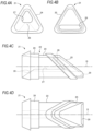
- FIGS. 4A to 4D illustrate the fine dust capturing device 21.
- FIG. 4A is a front view of the fine dust capturing device 21
- FIG. 4B is a back view of the fine dust capturing device 21
- FIG. 4C is a left side view of the fine dust capturing device 21
- FIG. 4D is a plan view of the fine dust capturing device 21.
- the fine dust capturing device 21 includes a main body portion 22, a water intake 26 for taking in water around the outboard motor 1, a passage 27 through which the water taken in from the water intake 26 flows, a filter 28 for capturing fine dust contained in the water by allowing the water flowing through the passage 27 to pass therethrough, and a water outlet 29 for discharging the water after passing through the filter 28 to a periphery of the outboard motor 1.
- the main body portion 22 is formed of, for example, resin or metal. As illustrated in FIG. 4C , the main body portion 22 has a passage forming portion 23, a water intake forming portion 24, and a water outlet forming portion 25.
- the passage forming portion 23 is formed in a tubular shape extending linearly. In the present embodiment, the passage forming portion 23 is formed in a triangular tubular shape having a substantially triangular cross-sectional shape. In FIG. 4C or FIG. 4D , D is an axis of the passage forming portion 23.
- the water intake forming portion 24 is attached and fixed to a portion on one axial end side of the passage forming portion 23 so as to cover one axial end side of the passage forming portion 23.
- the water outlet forming portion 25 is attached and fixed to a portion on the other axial end side of the passage forming portion 23 so as to cover the other axial end side of the passage forming portion 23.
- the water intake 26 is formed in the water intake forming portion 24.
- the water intake 26 is a hole penetrating the water intake forming portion 24.
- the water intake 26 is disposed such that a center thereof is positioned above the center of the water intake forming portion 24, and the center of the water intake 26 is positioned above the axis D of the passage forming portion 23.
- the water intake 26 has a substantially triangular shape obtained by reducing the substantially triangular cross-sectional shape of the passage forming portion 23.
- the water outlet 29 is formed in the water outlet forming portion 25.
- the water outlet 29 is a hole passing through the water outlet forming portion 25, the water outlet 29 is disposed such that a center thereof is positioned below the center of the water outlet forming portion 25, and the center of the water outlet 29 is positioned below the axis D of the passage forming portion 23.
- the water outlet 29 has a rectangular shape in which each corner portion is chamfered, and extends in a direction parallel to a bottom side of the substantially triangular cross section of the passage forming portion 23.
- the passage 27 is provided inside the passage forming portion 23 of the main body portion 22. One end of the passage 27 is connected to the water intake 26, and the other end of the passage 27 is connected to the water outlet 29.
- the passage 27 extends from the water intake 26 through the passage forming portion 23 in an axial direction to the water outlet 29.
- the filter 28 is provided in the middle of the passage 27.
- the filter 28 is disposed in a portion of the passage 27 on the rear side of the center thereof in the axial direction.
- the filter 28 is provided so as to block the entire cross section of the passage 27.
- the filter 28 is a filter capable of capturing fine dust, and is formed of, for example, a nonwoven fabric in a sheet shape or a plate shape. Water can pass through the filter 28, but fine dust cannot pass through the filter 28.
- the filter 28 has a multi-layer structure.
- the filter 28 includes a first layer having coarse openings and a second layer having fine openings.
- the filter 28 is disposed in the passage 27 such that the first layer is positioned on the water intake side and the second layer is positioned on the water outlet side. According to the structure and arrangement of the filter 28, when the water flows back through the passage 27 and flows in the direction from the water outlet 29 toward the water intake 26, it is possible to prevent the fine dust captured by the filter 28 from diffusing away from the filter 28.
- the fine dust contained in the water is captured by the first layer or the second layer, but continuing such a flow of water in the forward direction, the fine dust is accumulated in an intermediate portion between the first layer and the second layer, or inside the second layer.
- the fine dust accumulated inside the second layer or in the intermediate portion between the first layer and the second layer is pushed toward the water intake 26 by the water.
- the fine dust cannot easily pass through the first layer, most of the fine dust remains inside the second layer or in the intermediate portion between the first layer and the second layer. Accordingly, the fine dust captured by the filter 28 is prevented from diffusing away from the filter 28 by the backflow of water.
- a material of the filter 28 is not limited to the non-woven fabric, and may be woven fabric, sponge, glass mat, or the like.
- the filter 28 may be a single layer.
- the fine dust capturing device 21 is provided at the lower end portion of the support portion 8, specifically, between the lower end portion of the support portion 8 and the propeller unit case 6.
- the lower end portion of the support portion 8 has a bifurcated structure branched in the left-right direction.
- the lower end portion of the support portion 8 is provided with two coupling portions 9 that are respectively coupled to an upper left portion and an upper right portion of the propeller unit case 6.
- One coupling portion 9 extends downward from a left portion of the lower end portion of the support portion 8 while inclining leftward, and a lower end portion thereof is coupled to an upper left portion of a substantially intermediate portion of the propeller unit case 6 in the front-rear direction.
- the other coupling portion 9 extends downward from a right portion of the lower end portion of the support portion 8 while inclining rightward, and a lower end portion thereof is coupled to an upper right portion of the substantially intermediate portion of the propeller unit case 6 in the front-rear direction.
- the passage forming portion 23 of the main body portion 22 is formed in a triangular tubular shape as described above, but a shape of the passage forming portion 23 corresponds to a shape of the space between the lower end portion of the support portion 8 and the upper surface of the propeller unit case 6. Therefore, the fine dust capturing device 21 is provided so as to be fitted in the space formed between the lower end portion of the support portion 8 and the upper surface of the propeller unit case 6.
- an outer peripheral surface of the fine dust capturing device 21 (specifically, an outer peripheral surface of the water intake forming portion 24 and an outer peripheral surface of the water outlet forming portion 25) is in contact with an inner surface of each coupling portion 9 and the upper surface of the propeller unit case 6.
- the main body portion 22 of the fine dust capturing device 21 is disposed in the space between the lower end portion of the support portion 8 and the upper surface of the propeller unit case 6 such that the water intake 26 faces the front side of the outboard motor 1 and the water outlet 29 faces the rear side of the outboard motor 1.
- the water intake 26 faces the front side of the outboard motor 1
- the water outlet 29 faces the rear side of the outboard motor 1.
- the main body portion 22, the water intake 26, the passage 27, the filter 28, and the water outlet 29, that is, the fine dust capturing device 21 as a whole are positioned in front of the propeller 5, and when the outboard motor 1 is viewed from the front side or the rear side, the main body portion 22, the water intake 26, the passage 27, the filter 28, and the water outlet 29 are positioned inside a circle C having the same diameter as the diameter of the propeller 5, with a rotation center A of the propeller 5 as a center.
- the water intake 26 is disposed inside the circle C, above the propeller unit case 6, and at a position above the rotation center A of the propeller 5 in a vertical direction.
- the water intake 26 faces the front side of the outboard motor 1 from the position and in a direction parallel to an axis E of the propeller shaft 4.
- the water outlet 29 is disposed inside the circle C, above the propeller unit case 6, and above the rotation center A of the propeller 5 in the vertical direction.
- the water outlet 29 faces the rear side of the outboard motor 1 from the position and in the direction parallel to the axis E of the propeller shaft 4.
- the passage forming portion 23 is formed of a transparent resin. As illustrated in FIG. 2 , each of the coupling portions 9 is provided with a window 31. The window 31 is formed by a hole penetrating the coupling portion 9. The transparent passage forming portion 23 is disposed at a position corresponding to the window 31. Accordingly, the user can confirm the amount of fine dust accumulated in the filter 28 by looking through the window 31 when the outboard motor 1 is pulled up on the ground, for example.
- the fine dust capturing device 21 can be removed from the space formed between the lower end portion of the support portion 8 and the upper surface of the propeller unit case 6.
- the water outlet forming portion 25 is detachably attached to a rear portion of the passage forming portion 23.
- the filter 28 is detachably attached between a portion on a rear end side of the passage forming portion 23 and a portion on a front end side of the water outlet forming portion 25.
- the propeller unit 2 and the fine dust capturing device 21 sink below the water surface in a state in which the outboard motor 1 is attached to the transom of the ship on the water surface.
- water flows into the water intake 26 from the front side of the outboard motor 1.
- the water flowing into the water intake 26 flows rearward in the passage 27 toward the water outlet 29.
- the water flowing through the passage 27 toward the water outlet 29 passes through the filter 28.
- fine dust contained in the water is captured by the filter 28.
- the water passing through the filter 28 is discharged rearward from the water outlet 29.
- the water intake 26 is positioned below the water surface, is disposed at a front portion of the outboard motor 1, and faces the front side of the outboard motor 1. Therefore, the water flows into the passage 27 through the water intake 26 as the ship moves forward.
- the water outlet 29 is positioned below the water surface, is positioned in front of the propeller 5, and is positioned inside the circle C having the same diameter as the propeller 5, with the rotation center A of the propeller 5 as the center, when the outboard motor 1 is viewed from the rear side. In addition, the water outlet 29 faces the rear side of the outboard motor 1.
- a negative pressure is formed outside the water outlet 29 by the flow of water generated by the rotation of the propeller 5, and the water in the passage 27 is sucked to the outside of the passage 27 through the water outlet 29 by the negative pressure. Due to the pressure of the water flowing into the passage 27 via the water intake 26 and the negative pressure formed outside the water outlet 29 by the water flow generated by the rotation of the propeller 5, the water flows in the passage 27 from the water intake 26 toward the water outlet 29, and the water passes through the filter 28, whereby the fine dust is captured.
- the water outlet 29 of the fine dust capturing device 21 is positioned in front of the propeller 5, when the outboard motor 1 is viewed from the rear side, the water outlet 29 is positioned inside the circle C having the same diameter as the propeller 5, with the rotation center A of the propeller 5 as the center, and the water outlet 29 faces the rear side of the outboard motor 1. According to this configuration, the water in the passage 27 of the fine dust capturing device 21 can be sucked to the outside of the passage 27 through the water outlet 29 by using the negative pressure formed outside the water outlet 29 by the water flow generated by the rotation of the propeller 5.
- the flow rate of the water flowing through the passage 27 of the fine dust capturing device 21 can be increased, and thus the flow rate of the water passing through the filter 28 can be increased.
- the amount of fine dust captured per unit sailing time of the ship and the amount of fine dust captured per unit sailing distance of the ship can be increased, and a capturing efficiency of fine dust can be increased.
- the flow rate of the water flowing through the passage 27 of the fine dust capturing device 21 can be increased without adding a pump, it is possible to prevent complication of the structure of the fine dust capturing device 21, an increase in size of the outboard motor 1, and an increase in manufacturing cost of the outboard motor 1 due to the addition of the pump.
- the outboard motor 1 of the first embodiment it is possible to increase the capturing efficiency of the fine dust while avoiding complication of the structure of the fine dust capturing device 21, an increase in the size of the outboard motor 1, and an increase in the manufacturing cost of the outboard motor 1.
- the water outlet 29 of the fine dust capturing device 21 faces the rear side of the outboard motor 1 and in the direction parallel to the axis E of the propeller shaft 4.
- the negative pressure formed outside the water outlet 29 by the water flow generated by the rotation of the propeller 5 is increased, and thus a force of sucking the water in the passage 27 to the outside of the passage 27 through the water outlet 29 is increased. Accordingly, the flow rate of the water flowing through the passage 27 can be further increased, and the capturing efficiency of the fine dust can be further increased.
- the fine dust capturing device 21 includes the main body portion 22 formed in a tubular shape extending linearly, the water intake 26 is provided at one axial end portion of the main body portion 22, the water outlet 29 is provided at the other axial end portion of the main body portion 22, the passage 27 penetrates the main body portion 22 in the axial direction from the water intake 26 to reach the water outlet 29, and the filter 28 is provided in the middle of the passage 27.
- the passage 27 from the water intake 26 to the water outlet 29 can be shortened, and the entire passage 27 can be formed in a shape close to a straight line. Accordingly, a resistance of the water flowing through the passage 27 can be reduced.
- the fine dust capturing device 21 having such a configuration is disposed at a position in front of the propeller 5 and inside the circle C when the outboard motor 1 is viewed from the rear side such that the water intake 26 faces the front side of the outboard motor 1 and the water outlet 29 faces the rear side of the outboard motor 1, when the ship moves forward, the water around the outboard motor can smoothly flow into the passage 27 of the fine dust capturing device 21, the water flowing into the passage 27 can smoothly flow toward the water outlet 29, and the water in the passage 27 can smoothly flow out from the water outlet 29 using the negative pressure.
- the flow rate of water passing through the filter 28 can be increased, and the capturing efficiency of fine dust can be increased.
- the fine dust capturing device 21 is provided at the lower end portion of the support portion 8, specifically, between the lower end portion of the support portion 8 and the propeller unit case 6. Accordingly, the fine dust capturing device 21 can be easily disposed at the position in front of the propeller 5 and inside the circle C when the outboard motor 1 is viewed from the rear side.
- the fine dust capturing device 21 is in contact with an outer surface of the propeller unit case 6. As a result, the fine dust capturing device 21 can be brought very close to the propeller unit 2, and the fine dust capturing device 21 can be reliably placed in the water flow generated by the rotation of the propeller 5.
- An outboard motor according to a second embodiment of the present invention will be described with reference to FIG. 5 .
- the outboard motor according to the second embodiment of the present invention is different from the outboard motor 1 according to the first embodiment of the present invention in that the water outlet of the fine dust capturing device faces the rear side of the outboard motor and in a direction not parallel to the axis of the propeller shaft.
- FIG. 5 illustrates a state in which a lower portion of an outboard motor 41 according to the second embodiment of the present invention is viewed from the left.
- the outboard motor 41 includes a fine dust capturing device 51, and the fine dust capturing device 51 is provided at a lower end portion of a support portion 48 and in vicinity of a propeller unit case 46 of a propeller unit 42.
- the fine dust capturing device 51 is positioned in front of a propeller 45, and is positioned inside a circle having the same diameter as a diameter of the propeller 45, with a rotation center of the propeller 45 as a center, when the outboard motor 41 is viewed from the rear side.
- the fine dust capturing device 51 includes a main body portion 52 formed in a cylindrical shape.
- a water intake is provided in a front surface of the main body portion 52, a plurality of water outlets 59 are provided in a peripheral portion of a rear portion of the main body portion 52, a passage from the water intake to the water outlets 59 is provided in the main body portion 52, and a filter is provided in the middle of the passage.
- six water outlets 59 are disposed at intervals of 60 degrees in the peripheral portion of the rear portion of the main body portion 52.
- An outer diameter of the rear portion of the main body portion 52 decreases toward the rear, and as a result, an outer surface of the peripheral portion of the rear portion of the main body portion 52 is inclined.
- the six water outlets 59 are open to the inclined outer surface of the peripheral portion of the rear portion of the main body portion 52.
- the six water outlets 59 faces the rear side of the outboard motor 41 and in a direction not parallel to the axis E of the propeller shaft 44. That is, the six water outlets 59 face a left rear side, an upper left rear side, a lower left rear side, a right rear side, an upper right rear side, and a lower right rear side, respectively.
- the outboard motor 41 according to the second embodiment of the present invention having such a configuration, it is possible to obtain an effect that the water in the passage of the fine dust capturing device 51 is sucked to the outside of the passage through the water outlet 59 by the negative pressure formed by the water flow generated by the rotation of the propeller 45 when the ship moves forward. Accordingly, the flow rate of the water flowing through the passage of the fine dust capturing device 71 can be increased, and the capturing efficiency of fine dust can be increased.
- An outboard motor according to a third embodiment of the present invention will be described with reference to FIG. 6 .
- the outboard motor according to the third embodiment of the present invention is different from the outboard motor 1 according to the first embodiment of the present invention in that the water outlet of the fine dust capturing device faces in a direction parallel to a straight line orthogonal to the axis of the propeller shaft.
- FIG. 6 illustrates a state in which a lower portion of an outboard motor 61 according to the third embodiment of the present invention is viewed from the left.
- the outboard motor 61 is obtained by replacing the fine dust capturing device 51 in the outboard motor 41 according to the second embodiment of the present invention illustrated in FIG. 5 with a fine dust capturing device 71 having a water outlet oriented in a different direction.
- the fine dust capturing device 71 includes a main body portion 72 formed in a cylindrical shape.
- a water intake is provided in a front surface of the main body portion 72, a plurality of water outlets 79 are provided in a peripheral portion of a rear portion of the main body portion 72, a passage from the water intake to the water outlets 79 is provided in the main body portion 72, and a filter is provided in the middle of the passage.
- eight water outlets 79 are disposed at intervals of 45 degrees in the peripheral portion of the rear portion of the main body portion 72.
- the eight water outlets 79 face in a direction parallel to a straight line orthogonal to the axis E of the propeller shaft 44. That is, the eight water outlets 79 face an upper side, a lower side, the left side, the right side, an upper left side, a lower left side, an upper right side, and a lower right side, respectively.
- the outboard motor 61 according to the third embodiment of the present invention having such a configuration, it is possible to obtain an effect that the water in the passage of the fine dust capturing device 71 is sucked to the outside of the passage through the water outlet 79 by the negative pressure formed by the water flow generated by the rotation of the propeller 45 when the ship moves forward. Accordingly, the flow rate of the water flowing through the passage of the fine dust capturing device 71 can be increased, and the capturing efficiency of fine dust can be increased.
- An outboard motor according to a fourth embodiment of the present invention will be described with reference to FIG. 7 .
- the outboard motor according to the fourth embodiment of the present invention is different from the outboard motor 1 according to the first embodiment of the present invention in that the fine dust capturing device is disposed at a position not intersecting the axis of the support portion.
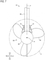
- FIG. 7 illustrates a state in which a lower portion of an outboard motor 81 according to the fourth embodiment of the invention is viewed from the front side.
- a lower end of the support portion 88 of the outboard motor 81 is fixed to a propeller unit case 86 of a propeller unit 82.
- a lower end portion of the support portion 88 does not have a bifurcated structure.
- each of the fine dust capturing devices 91 has the same configuration as the fine dust capturing device 21 illustrated in FIGS. 4A to 4D . Further, each of the fine dust capturing devices 91 is positioned in front of the propeller 85, and is positioned inside the circle C having the same diameter as the diameter of the propeller 85, with the rotation center A of the propeller 85 as a center, when the outboard motor 81 is viewed from the rear side. In addition, each of the fine dust capturing devices 91 is disposed such that the water intake faces the front side of the outboard motor 81 and the water outlet faces the rear side of the outboard motor 81.
- the outboard motor 81 according to the fourth embodiment of the present invention having such a configuration, it is possible to obtain an effect that the water in the passage of the fine dust capturing device 91 is sucked to the outside of the passage through the water outlet by the negative pressure formed by the water flow generated by the rotation of the propeller 85 when the ship moves forward. Accordingly, the flow rate of the water flowing through the passage of the fine dust capturing device 91 can be increased, and the capturing efficiency of fine dust can be increased.
- outboard motor 81 of the fourth embodiment of the present invention it is possible to easily form an outboard motor having a configuration in which a motor or an internal combustion engine is provided in the upper portion of the outboard motor, a drive shaft is provided in the support portion, a gear mechanism is provided in the propeller unit case of the propeller unit, and power of the motor is transmitted to the propeller shaft via the drive shaft and the gear mechanism.
- the fine dust capturing device 91 is disposed at a position where the fine dust capturing device 91 does not intersect with an axis F of the support portion 88, when the drive shaft is provided in the support portion 88, the drive shaft can be extended to the inside of the propeller unit case 86 of the propeller unit 82. Therefore, a lower end of the drive shaft is easily connected to the gear mechanism provided in the propeller unit case 86.
- the entire fine dust capturing device 21 (51, 71, 91) is positioned inside the circle having the same diameter as the propeller 5 (45, 85), with the rotation center of the propeller 5 (45, 85) as the center, but the present invention is not limited thereto.
- a portion other than the portion where the water outlet is disposed may be positioned outside a circle having the same diameter as the diameter of the propeller, with the rotation center of the propeller as the center.
- the water intake, a part of the passage, a filter, or the like may be positioned outside the circle.
- the case where the fine dust capturing device is provided between the lower end of the support portion and the propeller unit as illustrated in FIG. 2 and the case where the fine dust capturing device is provided at the lower end portion of the support portion as illustrated in FIG. 5 are taken as examples, but the present invention is not limited thereto.
- the fine dust capturing device may be provided in the propeller unit case of the propeller unit.
Landscapes
- Engineering & Computer Science (AREA)
- Chemical & Material Sciences (AREA)
- Combustion & Propulsion (AREA)
- Ocean & Marine Engineering (AREA)
- Mechanical Engineering (AREA)
- Environmental & Geological Engineering (AREA)
- Public Health (AREA)
- Health & Medical Sciences (AREA)
- Chemical Kinetics & Catalysis (AREA)
- Life Sciences & Earth Sciences (AREA)
- Organic Chemistry (AREA)
- Water Supply & Treatment (AREA)
- Hydrology & Water Resources (AREA)
- Filtering Materials (AREA)
Abstract
Description
- The present invention relates to an outboard motor for propelling a ship.
- In recent years, contamination due to fine dust such as microplastic has become a problem in sea, lakes, rivers and the like, and it is desired to recover such fine dust from sea, lakes, rivers and the like to purify sea, lakes, rivers and the like.
-
JP2021-169240A - Patent Literature 1:
JP2021-169240A - In order to promote purification of sea, lakes, rivers, and the like, it is desired to increase an amount of fine dust to be captured per unit sailing time of a ship or an amount of fine dust to be captured per unit sailing distance, thereby increasing a capturing efficiency of fine dust.
- In the fine dust capturing device provided in the outboard motor of the related art described in
JP2021-169240A - In the case of such a configuration, since the flow of water from when the water flows into the capturer through the water intake to when the water is discharged through the water outlet is generated only by the pressure of the water flowing into the water intake when the ship moves forward, it is difficult to increase the flow rate of the water flowing through the capturer, and thus it is difficult to increase the flow rate of the water passing through the filter. As a result, it is difficult to increase an amount of the fine dust captured per unit sailing time or the amount of the fine dust captured per unit sailing distance, and it is difficult to increase a capturing efficiency of the fine dust.
- In this regard, it is conceivable to add a pump to the fine dust capturing device and increase the flow rate of water flowing through the capturer by sucking water from the water intake by the pump. However, the addition of the pump is not preferable because it complicates the structure of the fine dust capturing device, increases the size of the outboard motor, and increases manufacturing cost of the outboard motor.
- The present invention has been made in view of the problems described above, and an object of the present invention is to provide an outboard motor capable of increasing a capturing efficiency of fine dust while avoiding complication of a structure of the fine dust capturing device, an increase in the size of the outboard motor, and an increase in manufacturing cost of the outboard motor.
- In order to solve the problems described above, according to the present invention, there is provided an outboard motor for propelling a ship, the outboard motor including: a propeller unit including a propeller shaft, a propeller fixed to the propeller shaft, and a case for rotatably supporting the propeller shaft; a support portion formed in a columnar shape extending in an upper-lower direction and having a lower portion to which the propeller unit is supported; a bracket provided at an upper portion of the support portion and configured to attach the support portion to the ship; and a fine dust capturing device provided on the propeller unit or the support portion, in which the fine dust capturing device includes a water intake for taking in water around the outboard motor, a passage through which the water taken in from the water intake flows, a filter for capturing fine dust contained in the water by allowing the water flowing through the passage to pass therethrough, and a water outlet for discharging the water after passing through the filter to a periphery of the outboard motor, and the water outlet is positioned in front of the propeller and inside a circle having the same diameter as a diameter of the propeller, with a rotation center of the propeller as a center, when the outboard motor is viewed from a rear side, and faces in a direction other than a front side of the outboard motor.
- According to the present invention, it is possible to increase the capturing efficiency of the fine dust while avoiding complication of the structure of the fine dust capturing device, an increase in the size of the outboard motor, and an increase in the manufacturing cost of the outboard motor.
-
-
FIG. 1 is a perspective view illustrating an outboard motor according to a first embodiment of the present invention. -
FIG. 2 is an explanatory view illustrating a state in which a lower portion of the outboard motor according to the first embodiment of the present invention is viewed from the left. -
FIG. 3A is an explanatory view illustrating a state in which the lower portion of the outboard motor according to the first embodiment of the present invention is viewed from a front side, andFIG. 3B is an explanatory view illustrating a state in which the lower portion of the outboard motor is viewed from a rear side. -
FIG. 4A is a front view of a fine dust capturing device in the outboard motor according to the first embodiment of the present invention,FIG. 4B is a back view of the fine dust capturing device,FIG. 4C is a left side view of the fine dust capturing device, andFIG. 4D is a plan view of the fine dust capturing device. -
FIG. 5 is an explanatory view illustrating an outboard motor according to a second embodiment of the present invention. -
FIG. 6 is an explanatory view illustrating an outboard motor according to a third embodiment of the present invention. -
FIG. 7 is an explanatory view illustrating an outboard motor according to a fourth embodiment of the present invention. - An outboard motor according to an embodiment of the present invention includes a propeller unit, a support portion formed in a columnar shape extending in an upper-lower direction and having a lower portion to which the propeller unit is supported, a bracket provided at an upper portion of the support portion and configured to attach the support portion to a ship, and a fine dust capturing device provided on the propeller unit or the support portion. The propeller unit includes a propeller shaft, a propeller fixed to the propeller shaft, and a case for rotatably supporting the propeller shaft.
- In the outboard motor according to the present embodiment, the fine dust capturing device includes a water intake for taking in water around the outboard motor, a passage through which the water taken in from the water intake flows, a filter for capturing fine dust contained in the water by allowing the water flowing through the passage to pass therethrough, and a water outlet for discharging the water after passing through the filter to a periphery of the outboard motor.
- The water outlet is positioned in front of the propeller. In addition, when the outboard motor is viewed from the rear side, the water outlet is positioned inside a circle having the same diameter as a diameter of the propeller, with a rotation center of the propeller as a center. Further, the water outlet faces in a direction other than a front side of the outboard motor, specifically, the water outlet faces a rear side, an upper side, a lower side, a left side, a right side, an upper left side, a lower left side, an upper right side, a lower right side, an upper rear side, a lower rear side, a left rear side, a right rear side, an upper left rear side, a lower left rear side, an upper right rear side, and a lower right rear side of the outboard motor.
- In the outboard motor according to the present embodiment, the water outlet of the fine dust capturing device is positioned in front of the propeller, and when the outboard motor is viewed from the rear side, the water outlet of the fine dust capturing device is positioned inside the circle having the same diameter as the diameter of the propeller, with the rotation center of the propeller as the center, and the water outlet of the fine dust capturing device faces a direction other than the front side of the outboard motor. According to such a configuration, a negative pressure is formed outside the water outlet of the fine dust capturing device by the flow of water generated by the rotation of the propeller, and the water in the passage of the fine dust capturing device is sucked to the outside of the passage through the water outlet by the negative pressure. Accordingly, the flow rate of the water flowing through the passage of the fine dust capturing device can be increased, and thus the flow rate of the water passing through the filter can be increased. As a result, an amount of fine dust captured per unit sailing time of the ship and an amount of fine dust captured per unit sailing distance of the ship can be increased, and a capturing efficiency of fine dust can be increased.
- According to the outboard motor of the present embodiment, since the flow rate of the water flowing through the passage of the fine dust capturing device can be increased without adding a pump, it is possible to prevent complication of the structure of the fine dust capturing device, an increase in size of the outboard motor, and an increase in manufacturing cost of the outboard motor due to the addition of the pump.
- An outboard motor according to a first embodiment of the present invention will be described with reference to
FIGS. 1 to 4D . In the first embodiment, when describing directions of upper (Ud), lower (Dd), front (Fd), rear (Bd), left (Ld), and right (Rd), arrows at the lower left and lower right inFIGS. 1 to 3B follow. -
FIG. 1 illustrates a state in which an outboard motor 1 according to the first embodiment of the present invention is viewed from the front upper left.FIG. 2 illustrates a state in which a lower portion of the outboard motor 1 is viewed from the left.FIG. 3A illustrates a state in which the lower portion of the outboard motor 1 is viewed from the front side.FIG. 3B illustrates a state in which the lower portion of the outboard motor 1 is viewed from the rear side. - The outboard motor 1 is a device that is attached to a transom of a ship to propel the ship. As illustrated in
FIG. 1 , the outboard motor 1 includes apropeller unit 2, a battery case 7, asupport portion 8, atransom bracket 17, aswivel bracket 18, abar handle 19, and a fine dust capturingdevice 21. - The
propeller unit 2 is disposed in a lower portion of the outboard motor 1, and is positioned below the water surface in a state in which the outboard motor 1 is attached to the ship. As illustrated inFIG. 2 , thepropeller unit 2 includes amotor 3, a propeller shaft 4, apropeller 5, and apropeller unit case 6. Themotor 3 is disposed at a front portion in thepropeller unit case 6. The propeller shaft 4 extends in a front-rear direction, and a front portion of the propeller shaft 4 is rotatably supported by a rear portion in thepropeller unit case 6. The propeller shaft 4 is connected to an output shaft of themotor 3, or is integrally formed with the output shaft of themotor 3, and is rotated by power of themotor 3. Thepropeller 5 is fixed to a rear end portion of the propeller shaft 4 and rotates integrally with the propeller shaft 4. Thepropeller 5 includes ahub 5A and a plurality ofblades 5B. Thepropeller unit case 6 is a sealed cylindrical case. - As illustrated in
FIG. 1 , the battery case 7 is disposed in an upper portion of the outboard motor 1, and is positioned above the water surface in a state in which the outboard motor 1 is attached to the ship. A battery that supplies electric power for driving themotor 3 to themotor 3 is accommodated in the battery case 7. - The
support portion 8 is a member that connects the battery case 7 and thepropeller unit 2 and supports both. Thepropeller unit 2 is supported by a lower portion of thesupport portion 8, and the battery case 7 is supported by an upper portion of thesupport portion 8. Specifically, thesupport portion 8 is formed in a columnar shape extending in an upper-lower direction, and thepropeller unit case 6 is fixed to the lower end portion of thesupport portion 8. Anattachment plate portion 15 is fixed to an upper end portion of thesupport portion 8, and the battery case 7 is detachably attached to theattachment plate portion 15. In addition, an outboardmotor carrying hand 16 for the user to carry the outboard motor 1 detached from the ship is provided at a rear portion of thesupport portion 8. - The
transom bracket 17 is a clamp mechanism for attaching the outboard motor 1 to the transom of the ship. Thetransom bracket 17 is disposed at a front portion of the upper portion of thesupport portion 8. - The
swivel bracket 18 is a bracket for making the outboard motor 1 attached to the transom rotatable in the left-right direction with respect to the ship, and is integrally formed with a rear portion of thetransom bracket 17. A steering shaft (not illustrated) is rotatably attached to theswivel bracket 18, and the steering shaft is fixed to the front portion of the upper portion of thesupport portion 8. Thesupport portion 8 can rotate with respect to theswivel bracket 18 with an axis of the steering shaft as a rotation axis, and as a result, the outboard motor 1 is rotatable in the left-right direction with respect to the ship. - The bar handle 19 is a handle that rotates the outboard motor 1 in the left-right direction with respect to the ship in order to steer the ship. The bar handle 19 is disposed above and in front of the
support portion 8. Specifically, a base end portion of the bar handle 19 is attached to the upper front end portion of theattachment plate portion 15. The user can rotate the outboard motor 1 to the right or left with respect to the ship by grasping a distal end portion of thebar handle 19 and moving the bar handle 19 to the left or right, and can change a direction of thepropeller 5 to the right or left. - As illustrated in
FIG. 2 , the outboard motor 1 includes the finedust capturing device 21. The finedust capturing device 21 is a device that captures fine dust diffused in a water area such as sea, lakes, or rivers where the ship sails. - The fine dust is, for example, fine dust having an outer diameter or a maximum length of 0.1 mm or more and 5 mm or less. Plastic dust flows into the sea, lakes, rivers, and the like, and is crushed by waves or a water flow, or is decomposed by ultraviolet light or the like into minute plastic pieces. The minute plastic pieces may diffuse in water such as sea, lakes, and rivers. Such a minute plastic piece is generally called microplastic. The microplastic corresponds to fine dust.
-
FIGS. 4A to 4D illustrate the finedust capturing device 21. Specifically,FIG. 4A is a front view of the finedust capturing device 21,FIG. 4B is a back view of the finedust capturing device 21,FIG. 4C is a left side view of the finedust capturing device 21, andFIG. 4D is a plan view of the finedust capturing device 21. - In
FIGS. 4A to 4D , the finedust capturing device 21 includes amain body portion 22, awater intake 26 for taking in water around the outboard motor 1, apassage 27 through which the water taken in from thewater intake 26 flows, afilter 28 for capturing fine dust contained in the water by allowing the water flowing through thepassage 27 to pass therethrough, and awater outlet 29 for discharging the water after passing through thefilter 28 to a periphery of the outboard motor 1. - The
main body portion 22 is formed of, for example, resin or metal. As illustrated inFIG. 4C , themain body portion 22 has apassage forming portion 23, a waterintake forming portion 24, and a wateroutlet forming portion 25. Thepassage forming portion 23 is formed in a tubular shape extending linearly. In the present embodiment, thepassage forming portion 23 is formed in a triangular tubular shape having a substantially triangular cross-sectional shape. InFIG. 4C or FIG. 4D , D is an axis of thepassage forming portion 23. The waterintake forming portion 24 is attached and fixed to a portion on one axial end side of thepassage forming portion 23 so as to cover one axial end side of thepassage forming portion 23. The wateroutlet forming portion 25 is attached and fixed to a portion on the other axial end side of thepassage forming portion 23 so as to cover the other axial end side of thepassage forming portion 23. - As illustrated in
FIG. 4A , thewater intake 26 is formed in the waterintake forming portion 24. Thewater intake 26 is a hole penetrating the waterintake forming portion 24. Thewater intake 26 is disposed such that a center thereof is positioned above the center of the waterintake forming portion 24, and the center of thewater intake 26 is positioned above the axis D of thepassage forming portion 23. In the present embodiment, thewater intake 26 has a substantially triangular shape obtained by reducing the substantially triangular cross-sectional shape of thepassage forming portion 23. - As illustrated in
FIG. 4B , thewater outlet 29 is formed in the wateroutlet forming portion 25. Thewater outlet 29 is a hole passing through the wateroutlet forming portion 25, thewater outlet 29 is disposed such that a center thereof is positioned below the center of the wateroutlet forming portion 25, and the center of thewater outlet 29 is positioned below the axis D of thepassage forming portion 23. In addition, in the present embodiment, thewater outlet 29 has a rectangular shape in which each corner portion is chamfered, and extends in a direction parallel to a bottom side of the substantially triangular cross section of thepassage forming portion 23. - As illustrated in
FIG. 4C , thepassage 27 is provided inside thepassage forming portion 23 of themain body portion 22. One end of thepassage 27 is connected to thewater intake 26, and the other end of thepassage 27 is connected to thewater outlet 29. Thepassage 27 extends from thewater intake 26 through thepassage forming portion 23 in an axial direction to thewater outlet 29. - The
filter 28 is provided in the middle of thepassage 27. In the present embodiment, thefilter 28 is disposed in a portion of thepassage 27 on the rear side of the center thereof in the axial direction. Thefilter 28 is provided so as to block the entire cross section of thepassage 27. Thefilter 28 is a filter capable of capturing fine dust, and is formed of, for example, a nonwoven fabric in a sheet shape or a plate shape. Water can pass through thefilter 28, but fine dust cannot pass through thefilter 28. - In the present embodiment, the
filter 28 has a multi-layer structure. For example, thefilter 28 includes a first layer having coarse openings and a second layer having fine openings. Thefilter 28 is disposed in thepassage 27 such that the first layer is positioned on the water intake side and the second layer is positioned on the water outlet side. According to the structure and arrangement of thefilter 28, when the water flows back through thepassage 27 and flows in the direction from thewater outlet 29 toward thewater intake 26, it is possible to prevent the fine dust captured by thefilter 28 from diffusing away from thefilter 28. That is, when the water flows in a forward direction from thewater intake 26 toward thewater outlet 29 in thepassage 27, the fine dust contained in the water is captured by the first layer or the second layer, but continuing such a flow of water in the forward direction, the fine dust is accumulated in an intermediate portion between the first layer and the second layer, or inside the second layer. On the other hand, when the water flows backward in thepassage 27 and flows in a reverse direction from thewater outlet 29 toward thewater intake 26, the fine dust accumulated inside the second layer or in the intermediate portion between the first layer and the second layer is pushed toward thewater intake 26 by the water. However, at this time, since the fine dust cannot easily pass through the first layer, most of the fine dust remains inside the second layer or in the intermediate portion between the first layer and the second layer. Accordingly, the fine dust captured by thefilter 28 is prevented from diffusing away from thefilter 28 by the backflow of water. - A material of the
filter 28 is not limited to the non-woven fabric, and may be woven fabric, sponge, glass mat, or the like. Thefilter 28 may be a single layer. - As illustrated in
FIG. 1 , the finedust capturing device 21 is provided at the lower end portion of thesupport portion 8, specifically, between the lower end portion of thesupport portion 8 and thepropeller unit case 6. In the present embodiment, the lower end portion of thesupport portion 8 has a bifurcated structure branched in the left-right direction. Specifically, as illustrated inFIG. 3A , the lower end portion of thesupport portion 8 is provided with twocoupling portions 9 that are respectively coupled to an upper left portion and an upper right portion of thepropeller unit case 6. Onecoupling portion 9 extends downward from a left portion of the lower end portion of thesupport portion 8 while inclining leftward, and a lower end portion thereof is coupled to an upper left portion of a substantially intermediate portion of thepropeller unit case 6 in the front-rear direction. Theother coupling portion 9 extends downward from a right portion of the lower end portion of thesupport portion 8 while inclining rightward, and a lower end portion thereof is coupled to an upper right portion of the substantially intermediate portion of thepropeller unit case 6 in the front-rear direction. With this structure, a space having a triangular shape in a front view is formed between the lower end portion of thesupport portion 8 and an upper surface (outer surface) of thepropeller unit case 6. The finedust capturing device 21 is disposed in this space. - In the fine
dust capturing device 21, thepassage forming portion 23 of themain body portion 22 is formed in a triangular tubular shape as described above, but a shape of thepassage forming portion 23 corresponds to a shape of the space between the lower end portion of thesupport portion 8 and the upper surface of thepropeller unit case 6. Therefore, the finedust capturing device 21 is provided so as to be fitted in the space formed between the lower end portion of thesupport portion 8 and the upper surface of thepropeller unit case 6. In a state in which the finedust capturing device 21 is provided in the space between the lower end portion of thesupport portion 8 and the upper surface of thepropeller unit case 6, an outer peripheral surface of the fine dust capturing device 21 (specifically, an outer peripheral surface of the waterintake forming portion 24 and an outer peripheral surface of the water outlet forming portion 25) is in contact with an inner surface of eachcoupling portion 9 and the upper surface of thepropeller unit case 6. - The
main body portion 22 of the finedust capturing device 21 is disposed in the space between the lower end portion of thesupport portion 8 and the upper surface of thepropeller unit case 6 such that thewater intake 26 faces the front side of the outboard motor 1 and thewater outlet 29 faces the rear side of the outboard motor 1. In addition, as illustrated inFIG. 3A or FIG. 3B , themain body portion 22, thewater intake 26, thepassage 27, thefilter 28, and thewater outlet 29, that is, the finedust capturing device 21 as a whole are positioned in front of thepropeller 5, and when the outboard motor 1 is viewed from the front side or the rear side, themain body portion 22, thewater intake 26, thepassage 27, thefilter 28, and thewater outlet 29 are positioned inside a circle C having the same diameter as the diameter of thepropeller 5, with a rotation center A of thepropeller 5 as a center. - As illustrated in
FIG. 3A , when the outboard motor 1 is viewed from the front side, thewater intake 26 is disposed inside the circle C, above thepropeller unit case 6, and at a position above the rotation center A of thepropeller 5 in a vertical direction. In addition, thewater intake 26 faces the front side of the outboard motor 1 from the position and in a direction parallel to an axis E of the propeller shaft 4. - As illustrated in
FIG. 3B , when the outboard motor 1 is viewed from the rear side, thewater outlet 29 is disposed inside the circle C, above thepropeller unit case 6, and above the rotation center A of thepropeller 5 in the vertical direction. In addition, thewater outlet 29 faces the rear side of the outboard motor 1 from the position and in the direction parallel to the axis E of the propeller shaft 4. - In the present embodiment, the
passage forming portion 23 is formed of a transparent resin. As illustrated inFIG. 2 , each of thecoupling portions 9 is provided with awindow 31. Thewindow 31 is formed by a hole penetrating thecoupling portion 9. The transparentpassage forming portion 23 is disposed at a position corresponding to thewindow 31. Accordingly, the user can confirm the amount of fine dust accumulated in thefilter 28 by looking through thewindow 31 when the outboard motor 1 is pulled up on the ground, for example. - In the present embodiment, the fine
dust capturing device 21 can be removed from the space formed between the lower end portion of thesupport portion 8 and the upper surface of thepropeller unit case 6. Further, in themain body portion 22 of the finedust capturing device 21, the wateroutlet forming portion 25 is detachably attached to a rear portion of thepassage forming portion 23. In themain body portion 22, thefilter 28 is detachably attached between a portion on a rear end side of thepassage forming portion 23 and a portion on a front end side of the wateroutlet forming portion 25. When the user pulls up the outboard motor 1 to the ground and looks through thewindow 31 to confirm that a large amount of fine dust is accumulated in thefilter 28, the user can remove the finedust capturing device 21 from the outboard motor 1 and replace thefilter 28. - In the fine
dust capturing device 21 having such a configuration, thepropeller unit 2 and the finedust capturing device 21 sink below the water surface in a state in which the outboard motor 1 is attached to the transom of the ship on the water surface. When thepropeller 5 rotates and the ship is moving forward by a propulsive force generated by thepropeller 5, water flows into thewater intake 26 from the front side of the outboard motor 1. The water flowing into thewater intake 26 flows rearward in thepassage 27 toward thewater outlet 29. The water flowing through thepassage 27 toward thewater outlet 29 passes through thefilter 28. When the water passes through thefilter 28, fine dust contained in the water is captured by thefilter 28. The water passing through thefilter 28 is discharged rearward from thewater outlet 29. - The
water intake 26 is positioned below the water surface, is disposed at a front portion of the outboard motor 1, and faces the front side of the outboard motor 1. Therefore, the water flows into thepassage 27 through thewater intake 26 as the ship moves forward. Thewater outlet 29 is positioned below the water surface, is positioned in front of thepropeller 5, and is positioned inside the circle C having the same diameter as thepropeller 5, with the rotation center A of thepropeller 5 as the center, when the outboard motor 1 is viewed from the rear side. In addition, thewater outlet 29 faces the rear side of the outboard motor 1. Therefore, a negative pressure is formed outside thewater outlet 29 by the flow of water generated by the rotation of thepropeller 5, and the water in thepassage 27 is sucked to the outside of thepassage 27 through thewater outlet 29 by the negative pressure. Due to the pressure of the water flowing into thepassage 27 via thewater intake 26 and the negative pressure formed outside thewater outlet 29 by the water flow generated by the rotation of thepropeller 5, the water flows in thepassage 27 from thewater intake 26 toward thewater outlet 29, and the water passes through thefilter 28, whereby the fine dust is captured. - As described above, in the outboard motor 1 according to the first embodiment of the present invention, the
water outlet 29 of the finedust capturing device 21 is positioned in front of thepropeller 5, when the outboard motor 1 is viewed from the rear side, thewater outlet 29 is positioned inside the circle C having the same diameter as thepropeller 5, with the rotation center A of thepropeller 5 as the center, and thewater outlet 29 faces the rear side of the outboard motor 1. According to this configuration, the water in thepassage 27 of the finedust capturing device 21 can be sucked to the outside of thepassage 27 through thewater outlet 29 by using the negative pressure formed outside thewater outlet 29 by the water flow generated by the rotation of thepropeller 5. Accordingly, the flow rate of the water flowing through thepassage 27 of the finedust capturing device 21 can be increased, and thus the flow rate of the water passing through thefilter 28 can be increased. As a result, the amount of fine dust captured per unit sailing time of the ship and the amount of fine dust captured per unit sailing distance of the ship can be increased, and a capturing efficiency of fine dust can be increased. According to this configuration, since the flow rate of the water flowing through thepassage 27 of the finedust capturing device 21 can be increased without adding a pump, it is possible to prevent complication of the structure of the finedust capturing device 21, an increase in size of the outboard motor 1, and an increase in manufacturing cost of the outboard motor 1 due to the addition of the pump. As described above, according to the outboard motor 1 of the first embodiment, it is possible to increase the capturing efficiency of the fine dust while avoiding complication of the structure of the finedust capturing device 21, an increase in the size of the outboard motor 1, and an increase in the manufacturing cost of the outboard motor 1. - In the outboard motor 1 according to the present embodiment, the
water outlet 29 of the finedust capturing device 21 faces the rear side of the outboard motor 1 and in the direction parallel to the axis E of the propeller shaft 4. According to this configuration, for example, compared to a case where thewater outlet 29 face the rear side of the outboard motor 1, in a direction not parallel to the axis E of the propeller shaft 4, or in a direction parallel to a straight line orthogonal to the axis E of the propeller shaft 4, the negative pressure formed outside thewater outlet 29 by the water flow generated by the rotation of thepropeller 5 is increased, and thus a force of sucking the water in thepassage 27 to the outside of thepassage 27 through thewater outlet 29 is increased. Accordingly, the flow rate of the water flowing through thepassage 27 can be further increased, and the capturing efficiency of the fine dust can be further increased. - In the outboard motor 1 according to the present embodiment, the fine
dust capturing device 21 includes themain body portion 22 formed in a tubular shape extending linearly, thewater intake 26 is provided at one axial end portion of themain body portion 22, thewater outlet 29 is provided at the other axial end portion of themain body portion 22, thepassage 27 penetrates themain body portion 22 in the axial direction from thewater intake 26 to reach thewater outlet 29, and thefilter 28 is provided in the middle of thepassage 27. With this configuration, in the finedust capturing device 21, thepassage 27 from thewater intake 26 to thewater outlet 29 can be shortened, and theentire passage 27 can be formed in a shape close to a straight line. Accordingly, a resistance of the water flowing through thepassage 27 can be reduced. Since the finedust capturing device 21 having such a configuration is disposed at a position in front of thepropeller 5 and inside the circle C when the outboard motor 1 is viewed from the rear side such that thewater intake 26 faces the front side of the outboard motor 1 and thewater outlet 29 faces the rear side of the outboard motor 1, when the ship moves forward, the water around the outboard motor can smoothly flow into thepassage 27 of the finedust capturing device 21, the water flowing into thepassage 27 can smoothly flow toward thewater outlet 29, and the water in thepassage 27 can smoothly flow out from thewater outlet 29 using the negative pressure. Thus, the flow rate of water passing through thefilter 28 can be increased, and the capturing efficiency of fine dust can be increased. - In the outboard motor 1 according to the present embodiment, the fine
dust capturing device 21 is provided at the lower end portion of thesupport portion 8, specifically, between the lower end portion of thesupport portion 8 and thepropeller unit case 6. Accordingly, the finedust capturing device 21 can be easily disposed at the position in front of thepropeller 5 and inside the circle C when the outboard motor 1 is viewed from the rear side. - The fine
dust capturing device 21 is in contact with an outer surface of thepropeller unit case 6. As a result, the finedust capturing device 21 can be brought very close to thepropeller unit 2, and the finedust capturing device 21 can be reliably placed in the water flow generated by the rotation of thepropeller 5. - An outboard motor according to a second embodiment of the present invention will be described with reference to
FIG. 5 . In the second embodiment, when describing directions of the upper (Ud), the lower (Dd), the front (Fd), and the rear (Bd), arrows at the lower left inFIG. 5 follow. The outboard motor according to the second embodiment of the present invention is different from the outboard motor 1 according to the first embodiment of the present invention in that the water outlet of the fine dust capturing device faces the rear side of the outboard motor and in a direction not parallel to the axis of the propeller shaft. -
FIG. 5 illustrates a state in which a lower portion of anoutboard motor 41 according to the second embodiment of the present invention is viewed from the left. InFIG. 5 , theoutboard motor 41 includes a finedust capturing device 51, and the finedust capturing device 51 is provided at a lower end portion of asupport portion 48 and in vicinity of apropeller unit case 46 of apropeller unit 42. The finedust capturing device 51 is positioned in front of apropeller 45, and is positioned inside a circle having the same diameter as a diameter of thepropeller 45, with a rotation center of thepropeller 45 as a center, when theoutboard motor 41 is viewed from the rear side. The finedust capturing device 51 includes amain body portion 52 formed in a cylindrical shape. In addition, a water intake is provided in a front surface of themain body portion 52, a plurality ofwater outlets 59 are provided in a peripheral portion of a rear portion of themain body portion 52, a passage from the water intake to thewater outlets 59 is provided in themain body portion 52, and a filter is provided in the middle of the passage. - Specifically, six
water outlets 59 are disposed at intervals of 60 degrees in the peripheral portion of the rear portion of themain body portion 52. An outer diameter of the rear portion of themain body portion 52 decreases toward the rear, and as a result, an outer surface of the peripheral portion of the rear portion of themain body portion 52 is inclined. The sixwater outlets 59 are open to the inclined outer surface of the peripheral portion of the rear portion of themain body portion 52. The sixwater outlets 59 faces the rear side of theoutboard motor 41 and in a direction not parallel to the axis E of thepropeller shaft 44. That is, the sixwater outlets 59 face a left rear side, an upper left rear side, a lower left rear side, a right rear side, an upper right rear side, and a lower right rear side, respectively. - Also in the
outboard motor 41 according to the second embodiment of the present invention having such a configuration, it is possible to obtain an effect that the water in the passage of the finedust capturing device 51 is sucked to the outside of the passage through thewater outlet 59 by the negative pressure formed by the water flow generated by the rotation of thepropeller 45 when the ship moves forward. Accordingly, the flow rate of the water flowing through the passage of the finedust capturing device 71 can be increased, and the capturing efficiency of fine dust can be increased. - An outboard motor according to a third embodiment of the present invention will be described with reference to
FIG. 6 . In the third embodiment, when describing directions of the upper (Ud), the lower (Dd), the front (Fd), and the rear (Bd), arrows at the lower left inFIG. 6 follow. The outboard motor according to the third embodiment of the present invention is different from the outboard motor 1 according to the first embodiment of the present invention in that the water outlet of the fine dust capturing device faces in a direction parallel to a straight line orthogonal to the axis of the propeller shaft. -
FIG. 6 illustrates a state in which a lower portion of anoutboard motor 61 according to the third embodiment of the present invention is viewed from the left. InFIG. 6 , theoutboard motor 61 is obtained by replacing the finedust capturing device 51 in theoutboard motor 41 according to the second embodiment of the present invention illustrated inFIG. 5 with a finedust capturing device 71 having a water outlet oriented in a different direction. The finedust capturing device 71 includes amain body portion 72 formed in a cylindrical shape. In addition, a water intake is provided in a front surface of themain body portion 72, a plurality ofwater outlets 79 are provided in a peripheral portion of a rear portion of themain body portion 72, a passage from the water intake to thewater outlets 79 is provided in themain body portion 72, and a filter is provided in the middle of the passage. - Specifically, eight
water outlets 79 are disposed at intervals of 45 degrees in the peripheral portion of the rear portion of themain body portion 72. The eightwater outlets 79 face in a direction parallel to a straight line orthogonal to the axis E of thepropeller shaft 44. That is, the eightwater outlets 79 face an upper side, a lower side, the left side, the right side, an upper left side, a lower left side, an upper right side, and a lower right side, respectively. - Also in the
outboard motor 61 according to the third embodiment of the present invention having such a configuration, it is possible to obtain an effect that the water in the passage of the finedust capturing device 71 is sucked to the outside of the passage through thewater outlet 79 by the negative pressure formed by the water flow generated by the rotation of thepropeller 45 when the ship moves forward. Accordingly, the flow rate of the water flowing through the passage of the finedust capturing device 71 can be increased, and the capturing efficiency of fine dust can be increased. - An outboard motor according to a fourth embodiment of the present invention will be described with reference to
FIG. 7 . In the fourth embodiment, when describing the directions of the upper (Ud), the lower (Dd), the left (Ld), and the right (Rd), arrows at the lower left inFIG. 7 follow. The outboard motor according to the fourth embodiment of the present invention is different from the outboard motor 1 according to the first embodiment of the present invention in that the fine dust capturing device is disposed at a position not intersecting the axis of the support portion. -
FIG. 7 illustrates a state in which a lower portion of anoutboard motor 81 according to the fourth embodiment of the invention is viewed from the front side. InFIG. 7 , a lower end of thesupport portion 88 of theoutboard motor 81 is fixed to apropeller unit case 86 of apropeller unit 82. Unlike thesupport portion 8 illustrated inFIG. 3A , a lower end portion of thesupport portion 88 does not have a bifurcated structure. Further, two finedust capturing devices 91 are provided at the lower end portion of thesupport portion 88, one finedust capturing device 91 is disposed on a left side of the lower end portion of thesupport portion 88, and the other finedust capturing device 91 is disposed on a right side of the lower end portion of thesupport portion 88. Each of the finedust capturing devices 91 has the same configuration as the finedust capturing device 21 illustrated inFIGS. 4A to 4D . Further, each of the finedust capturing devices 91 is positioned in front of thepropeller 85, and is positioned inside the circle C having the same diameter as the diameter of thepropeller 85, with the rotation center A of thepropeller 85 as a center, when theoutboard motor 81 is viewed from the rear side. In addition, each of the finedust capturing devices 91 is disposed such that the water intake faces the front side of theoutboard motor 81 and the water outlet faces the rear side of theoutboard motor 81. - Also in the
outboard motor 81 according to the fourth embodiment of the present invention having such a configuration, it is possible to obtain an effect that the water in the passage of the finedust capturing device 91 is sucked to the outside of the passage through the water outlet by the negative pressure formed by the water flow generated by the rotation of thepropeller 85 when the ship moves forward. Accordingly, the flow rate of the water flowing through the passage of the finedust capturing device 91 can be increased, and the capturing efficiency of fine dust can be increased. - According to the
outboard motor 81 of the fourth embodiment of the present invention, it is possible to easily form an outboard motor having a configuration in which a motor or an internal combustion engine is provided in the upper portion of the outboard motor, a drive shaft is provided in the support portion, a gear mechanism is provided in the propeller unit case of the propeller unit, and power of the motor is transmitted to the propeller shaft via the drive shaft and the gear mechanism. That is, in theoutboard motor 81, since the finedust capturing device 91 is disposed at a position where the finedust capturing device 91 does not intersect with an axis F of thesupport portion 88, when the drive shaft is provided in thesupport portion 88, the drive shaft can be extended to the inside of thepropeller unit case 86 of thepropeller unit 82. Therefore, a lower end of the drive shaft is easily connected to the gear mechanism provided in thepropeller unit case 86. - In each of the above embodiments, when the outboard motor 1 (41, 61, 81) is viewed from the rear side, the entire fine dust capturing device 21 (51, 71, 91) is positioned inside the circle having the same diameter as the propeller 5 (45, 85), with the rotation center of the propeller 5 (45, 85) as the center, but the present invention is not limited thereto. When the outboard motor is viewed from the rear side, in the fine dust capturing device, a portion other than the portion where the water outlet is disposed may be positioned outside a circle having the same diameter as the diameter of the propeller, with the rotation center of the propeller as the center. For example, the water intake, a part of the passage, a filter, or the like may be positioned outside the circle.
- In the above embodiments, the case where the fine dust capturing device is provided between the lower end of the support portion and the propeller unit as illustrated in
FIG. 2 and the case where the fine dust capturing device is provided at the lower end portion of the support portion as illustrated inFIG. 5 are taken as examples, but the present invention is not limited thereto. The fine dust capturing device may be provided in the propeller unit case of the propeller unit. - The present invention can be appropriately changed without departing from the gist or concept of the invention which can be read from the claims and the entire specification, and an outboard motor with such a change is also included in the technical concept of the present invention.
-
- 1, 41, 61, 81 outboard motor
- 2, 42, 82 propeller unit
- 4, 44 propeller shaft
- 5, 45, 85 propeller
- 6, 46, 86 propeller unit case (case)
- 8, 48, 88 support portion
- 11 transom bracket (bracket)
- 21, 51, 71, 91 fine dust capturing device
- 22, 52, 72 main body portion
- 26 water intake
- 27 passage
- 28 filter
- 29, 59, 79 water outlet
Claims (8)
- An outboard motor (1) for propelling a ship, the outboard motor comprising:a propeller unit (2, 42, 82) including a propeller shaft (4, 44), a propeller (5, 45, 85) fixed to the propeller shaft, and a case (6, 46, 86) for rotatably supporting the propeller shaft;a support portion (8, 48, 88) formed in a columnar shape extending in an upper-lower direction and having a lower portion to which the propeller unit is supported;a bracket (11) provided at an upper portion of the support portion and configured to attach the support portion to the ship; anda fine dust capturing device (21) provided on the propeller unit or the support portion, whereinthe fine dust capturing device (21) includes a water intake (26) for taking in water around the outboard motor (1), a passage (27) through which the water taken in from the water intake (26) flows, a filter for capturing fine dust contained in the water by allowing the water flowing through the passage (27) to pass therethrough, and a water outlet (29) for discharging the water after passing through the filter to a periphery of the outboard motor (1), andthe water outlet (29) is positioned in front of the propeller (5) and inside a circle (C) having the same diameter as a diameter of the propeller (5), with a rotation center (A) of the propeller (5) as a center, when the outboard motor (1) is viewed from a rear side, and faces in a direction other than a front side of the outboard motor (1).
- The outboard motor according to claim 1, wherein
the water outlet face a rear side of the outboard motor. - The outboard motor according to claim 1, wherein
the water outlet faces a rear side of the outboard motor and in a direction parallel to an axis of the propeller shaft. - The outboard motor according to claim 1, wherein
the water intake, the passage, the filter, and the water outlet are positioned in front of the propeller and inside a circle having the same diameter as the diameter of the propeller, with the rotation center of the propeller as the center, when the outboard motor is viewed from the rear side. - The outboard motor according to claim 1, wherein
the fine dust capturing device includes a main body portion formed in a tubular shape extending linearly, the water intake is provided at one axial end portion of the main body portion, the water outlet is provided at the other axial end portion of the main body portion, the passage penetrates the main body portion in an axial direction from the water intake to reach the water outlet, and the filter is provided in the middle of the passage. - The outboard motor according to claim 5, wherein
the main body portion is provided in the propeller unit or the support portion such that the water intake faces the front side of the outboard motor and the water outlet faces a rear side of the outboard motor. - The outboard motor according to claim 1, wherein
the fine dust capturing device is provided at a lower end portion of the support portion. - The outboard motor according to claim 7, wherein
the fine dust capturing device is in contact with an outer surface of the case.
Applications Claiming Priority (1)
| Application Number | Priority Date | Filing Date | Title |
|---|---|---|---|
| JP2023148166A JP2025041090A (en) | 2023-09-13 | 2023-09-13 | Outboard motor |
Publications (2)
| Publication Number | Publication Date |
|---|---|
| EP4524019A1 true EP4524019A1 (en) | 2025-03-19 |
| EP4524019B1 EP4524019B1 (en) | 2026-03-04 |
Family
ID=92593305
Family Applications (1)
| Application Number | Title | Priority Date | Filing Date |
|---|---|---|---|
| EP24196833.8A Active EP4524019B1 (en) | 2023-09-13 | 2024-08-27 | Outboard motor |
Country Status (3)
| Country | Link |
|---|---|
| US (1) | US20250083787A1 (en) |
| EP (1) | EP4524019B1 (en) |
| JP (1) | JP2025041090A (en) |
Citations (4)
| Publication number | Priority date | Publication date | Assignee | Title |
|---|---|---|---|---|
| CN110329463A (en) * | 2019-06-28 | 2019-10-15 | 南京理工大学 | A kind of multi-functional micro- plastic collection device peculiar to vessel |
| US20210001970A1 (en) * | 2019-07-01 | 2021-01-07 | Suzuki Motor Corporation | Outboard motor |
| US20210316833A1 (en) * | 2020-04-14 | 2021-10-14 | Suzuki Motor Corporation | Ship propulsion machine |
| US20230219674A1 (en) * | 2022-01-12 | 2023-07-13 | Suzuki Motor Corporation | Cooling device for ship propulsion machine |
-
2023
- 2023-09-13 JP JP2023148166A patent/JP2025041090A/en active Pending
-
2024
- 2024-08-26 US US18/814,916 patent/US20250083787A1/en active Pending
- 2024-08-27 EP EP24196833.8A patent/EP4524019B1/en active Active
Patent Citations (5)
| Publication number | Priority date | Publication date | Assignee | Title |
|---|---|---|---|---|
| CN110329463A (en) * | 2019-06-28 | 2019-10-15 | 南京理工大学 | A kind of multi-functional micro- plastic collection device peculiar to vessel |
| US20210001970A1 (en) * | 2019-07-01 | 2021-01-07 | Suzuki Motor Corporation | Outboard motor |
| US20210316833A1 (en) * | 2020-04-14 | 2021-10-14 | Suzuki Motor Corporation | Ship propulsion machine |
| JP2021169240A (en) | 2020-04-14 | 2021-10-28 | スズキ株式会社 | Ship propulsion machine |
| US20230219674A1 (en) * | 2022-01-12 | 2023-07-13 | Suzuki Motor Corporation | Cooling device for ship propulsion machine |
Also Published As
| Publication number | Publication date |
|---|---|
| JP2025041090A (en) | 2025-03-26 |
| US20250083787A1 (en) | 2025-03-13 |
| EP4524019B1 (en) | 2026-03-04 |
Similar Documents
| Publication | Publication Date | Title |
|---|---|---|
| EP4538163A1 (en) | Outboard motor | |
| US12359385B2 (en) | Foreign matter collecting device | |
| EP1050454A3 (en) | External electric drive propulsion module arrangement for SWATH vessels | |
| EP4524019B1 (en) | Outboard motor | |
| JP2023102497A (en) | Cooling device for ship propulsion | |
| WO2002062659A1 (en) | Outboard motor | |
| CN212447974U (en) | Power surfboard | |
| US5376027A (en) | Marine propulsion mechanism for water craft | |
| US20130175714A1 (en) | Personal Cooling Device | |
| EP4524020B1 (en) | Fine dust capturing device | |
| JP2020116478A (en) | Underwater cleaning work machine | |
| CN221820203U (en) | Water sampling unmanned boat | |
| CN114230004A (en) | External wastewater treatment anaerobic MBR technical device | |
| US10689079B2 (en) | Jet pump systems | |
| US9193426B2 (en) | Watercraft propulsion system and method of propelling a watercraft through water | |
| CN221269157U (en) | Pool robot | |
| CN219154715U (en) | Propeller and wireless remote control ship | |
| CN224241223U (en) | Water surface cleaner | |
| JPH05245485A (en) | Water purification boat | |
| CN215667656U (en) | Jacking device internal mold shrinkage type integrated three-grid septic tank equipment | |
| JPH0277391A (en) | Bilge water drainage device of water jet propulsion vessel | |
| JP5314402B2 (en) | Shell crusher equipment | |
| JP3951217B2 (en) | Manpowered boat | |
| CN117657412A (en) | a paddle | |
| JPH0655999U (en) | Propulsion device and ship |
Legal Events
| Date | Code | Title | Description |
|---|---|---|---|
| PUAI | Public reference made under article 153(3) epc to a published international application that has entered the european phase |
Free format text: ORIGINAL CODE: 0009012 |
|
| STAA | Information on the status of an ep patent application or granted ep patent |
Free format text: STATUS: REQUEST FOR EXAMINATION WAS MADE |
|
| 17P | Request for examination filed |
Effective date: 20240827 |
|
| AK | Designated contracting states |
Kind code of ref document: A1 Designated state(s): AL AT BE BG CH CY CZ DE DK EE ES FI FR GB GR HR HU IE IS IT LI LT LU LV MC ME MK MT NL NO PL PT RO RS SE SI SK SM TR |
|
| GRAP | Despatch of communication of intention to grant a patent |
Free format text: ORIGINAL CODE: EPIDOSNIGR1 |
|
| STAA | Information on the status of an ep patent application or granted ep patent |
Free format text: STATUS: GRANT OF PATENT IS INTENDED |
|
| RIC1 | Information provided on ipc code assigned before grant |
Ipc: B63B 35/32 20060101AFI20250923BHEP Ipc: B63H 20/00 20060101ALI20250923BHEP Ipc: E02B 15/00 20060101ALI20250923BHEP |
|
| INTG | Intention to grant announced |
Effective date: 20251001 |
|
| GRAS | Grant fee paid |
Free format text: ORIGINAL CODE: EPIDOSNIGR3 |
|
| GRAA | (expected) grant |
Free format text: ORIGINAL CODE: 0009210 |
|
| STAA | Information on the status of an ep patent application or granted ep patent |
Free format text: STATUS: THE PATENT HAS BEEN GRANTED |
|
| AK | Designated contracting states |
Kind code of ref document: B1 Designated state(s): AL AT BE BG CH CY CZ DE DK EE ES FI FR GB GR HR HU IE IS IT LI LT LU LV MC ME MK MT NL NO PL PT RO RS SE SI SK SM TR |
|
| REG | Reference to a national code |
Ref country code: CH Ref legal event code: F10 Free format text: ST27 STATUS EVENT CODE: U-0-0-F10-F00 (AS PROVIDED BY THE NATIONAL OFFICE) Effective date: 20260304 Ref country code: GB Ref legal event code: FG4D |
|
| REG | Reference to a national code |
Ref country code: IE Ref legal event code: FG4D |
|
| REG | Reference to a national code |
Ref country code: DE Ref legal event code: R096 Ref document number: 602024002973 Country of ref document: DE |
|
| PG25 | Lapsed in a contracting state [announced via postgrant information from national office to epo] |
Ref country code: RS Free format text: LAPSE BECAUSE OF FAILURE TO SUBMIT A TRANSLATION OF THE DESCRIPTION OR TO PAY THE FEE WITHIN THE PRESCRIBED TIME-LIMIT Effective date: 20260604 |
|
| PG25 | Lapsed in a contracting state [announced via postgrant information from national office to epo] |
Ref country code: ES Free format text: LAPSE BECAUSE OF FAILURE TO SUBMIT A TRANSLATION OF THE DESCRIPTION OR TO PAY THE FEE WITHIN THE PRESCRIBED TIME-LIMIT Effective date: 20260304 |
|
| REG | Reference to a national code |
Ref country code: NL Ref legal event code: MP Effective date: 20260304 |
|
| PG25 | Lapsed in a contracting state [announced via postgrant information from national office to epo] |
Ref country code: PL Free format text: LAPSE BECAUSE OF FAILURE TO SUBMIT A TRANSLATION OF THE DESCRIPTION OR TO PAY THE FEE WITHIN THE PRESCRIBED TIME-LIMIT Effective date: 20260304 |
|
| PG25 | Lapsed in a contracting state [announced via postgrant information from national office to epo] |
Ref country code: GR Free format text: LAPSE BECAUSE OF FAILURE TO SUBMIT A TRANSLATION OF THE DESCRIPTION OR TO PAY THE FEE WITHIN THE PRESCRIBED TIME-LIMIT Effective date: 20260605 |
|
| REG | Reference to a national code |
Ref country code: LT Ref legal event code: MG9D |
|
| PG25 | Lapsed in a contracting state [announced via postgrant information from national office to epo] |
Ref country code: LT Free format text: LAPSE BECAUSE OF FAILURE TO SUBMIT A TRANSLATION OF THE DESCRIPTION OR TO PAY THE FEE WITHIN THE PRESCRIBED TIME-LIMIT Effective date: 20260304 |
|
| PG25 | Lapsed in a contracting state [announced via postgrant information from national office to epo] |
Ref country code: NO Free format text: LAPSE BECAUSE OF FAILURE TO SUBMIT A TRANSLATION OF THE DESCRIPTION OR TO PAY THE FEE WITHIN THE PRESCRIBED TIME-LIMIT Effective date: 20260604 |
|
| PG25 | Lapsed in a contracting state [announced via postgrant information from national office to epo] |
Ref country code: SE Free format text: LAPSE BECAUSE OF FAILURE TO SUBMIT A TRANSLATION OF THE DESCRIPTION OR TO PAY THE FEE WITHIN THE PRESCRIBED TIME-LIMIT Effective date: 20260304 Ref country code: FI Free format text: LAPSE BECAUSE OF FAILURE TO SUBMIT A TRANSLATION OF THE DESCRIPTION OR TO PAY THE FEE WITHIN THE PRESCRIBED TIME-LIMIT Effective date: 20260304 |
|
| PG25 | Lapsed in a contracting state [announced via postgrant information from national office to epo] |
Ref country code: HR Free format text: LAPSE BECAUSE OF FAILURE TO SUBMIT A TRANSLATION OF THE DESCRIPTION OR TO PAY THE FEE WITHIN THE PRESCRIBED TIME-LIMIT Effective date: 20260304 |
|
| PG25 | Lapsed in a contracting state [announced via postgrant information from national office to epo] |
Ref country code: LV Free format text: LAPSE BECAUSE OF FAILURE TO SUBMIT A TRANSLATION OF THE DESCRIPTION OR TO PAY THE FEE WITHIN THE PRESCRIBED TIME-LIMIT Effective date: 20260304 |
|
| PG25 | Lapsed in a contracting state [announced via postgrant information from national office to epo] |
Ref country code: BG Free format text: LAPSE BECAUSE OF FAILURE TO SUBMIT A TRANSLATION OF THE DESCRIPTION OR TO PAY THE FEE WITHIN THE PRESCRIBED TIME-LIMIT Effective date: 20260304 |