EP4524007A1 - Saddle having laser projection direction-indicating device and bicycle equipped with the saddle - Google Patents
Saddle having laser projection direction-indicating device and bicycle equipped with the saddle Download PDFInfo
- Publication number
- EP4524007A1 EP4524007A1 EP23202581.7A EP23202581A EP4524007A1 EP 4524007 A1 EP4524007 A1 EP 4524007A1 EP 23202581 A EP23202581 A EP 23202581A EP 4524007 A1 EP4524007 A1 EP 4524007A1
- Authority
- EP
- European Patent Office
- Prior art keywords
- saddle
- control unit
- laser projection
- generate
- turn signal
- Prior art date
- Legal status (The legal status is an assumption and is not a legal conclusion. Google has not performed a legal analysis and makes no representation as to the accuracy of the status listed.)
- Withdrawn
Links
Images


Classifications
-
- B—PERFORMING OPERATIONS; TRANSPORTING
- B62—LAND VEHICLES FOR TRAVELLING OTHERWISE THAN ON RAILS
- B62J—CYCLE SADDLES OR SEATS; AUXILIARY DEVICES OR ACCESSORIES SPECIALLY ADAPTED TO CYCLES AND NOT OTHERWISE PROVIDED FOR, e.g. ARTICLE CARRIERS OR CYCLE PROTECTORS
- B62J1/00—Saddles or other seats for cycles; Arrangement thereof; Component parts
-
- B—PERFORMING OPERATIONS; TRANSPORTING
- B62—LAND VEHICLES FOR TRAVELLING OTHERWISE THAN ON RAILS
- B62J—CYCLE SADDLES OR SEATS; AUXILIARY DEVICES OR ACCESSORIES SPECIALLY ADAPTED TO CYCLES AND NOT OTHERWISE PROVIDED FOR, e.g. ARTICLE CARRIERS OR CYCLE PROTECTORS
- B62J6/00—Arrangement of optical signalling or lighting devices on cycles; Mounting or supporting thereof; Circuits therefor
- B62J6/05—Direction indicators
- B62J6/055—Electrical means, e.g. lamps
- B62J6/056—Electrical means, e.g. lamps characterised by control means
- B62J6/057—Automatic activation, e.g. by sensors
-
- B—PERFORMING OPERATIONS; TRANSPORTING
- B60—VEHICLES IN GENERAL
- B60Q—ARRANGEMENT OF SIGNALLING OR LIGHTING DEVICES, THE MOUNTING OR SUPPORTING THEREOF OR CIRCUITS THEREFOR, FOR VEHICLES IN GENERAL
- B60Q1/00—Arrangement of optical signalling or lighting devices, the mounting or supporting thereof or circuits therefor
- B60Q1/26—Arrangement of optical signalling or lighting devices, the mounting or supporting thereof or circuits therefor the devices being primarily intended to indicate the vehicle, or parts thereof, or to give signals, to other traffic
- B60Q1/2661—Arrangement of optical signalling or lighting devices, the mounting or supporting thereof or circuits therefor the devices being primarily intended to indicate the vehicle, or parts thereof, or to give signals, to other traffic mounted on parts having other functions
- B60Q1/2673—Arrangement of optical signalling or lighting devices, the mounting or supporting thereof or circuits therefor the devices being primarily intended to indicate the vehicle, or parts thereof, or to give signals, to other traffic mounted on parts having other functions on parts worn by the driver, e.g. clothes, gloves or bags, specially adapted to provide auxiliary vehicle signalling
- B60Q1/2676—Helmets
-
- B—PERFORMING OPERATIONS; TRANSPORTING
- B60—VEHICLES IN GENERAL
- B60Q—ARRANGEMENT OF SIGNALLING OR LIGHTING DEVICES, THE MOUNTING OR SUPPORTING THEREOF OR CIRCUITS THEREFOR, FOR VEHICLES IN GENERAL
- B60Q1/00—Arrangement of optical signalling or lighting devices, the mounting or supporting thereof or circuits therefor
- B60Q1/26—Arrangement of optical signalling or lighting devices, the mounting or supporting thereof or circuits therefor the devices being primarily intended to indicate the vehicle, or parts thereof, or to give signals, to other traffic
- B60Q1/34—Arrangement of optical signalling or lighting devices, the mounting or supporting thereof or circuits therefor the devices being primarily intended to indicate the vehicle, or parts thereof, or to give signals, to other traffic for indicating change of drive direction
- B60Q1/38—Arrangement of optical signalling or lighting devices, the mounting or supporting thereof or circuits therefor the devices being primarily intended to indicate the vehicle, or parts thereof, or to give signals, to other traffic for indicating change of drive direction using immovably-mounted light sources, e.g. fixed flashing lamps
-
- B—PERFORMING OPERATIONS; TRANSPORTING
- B62—LAND VEHICLES FOR TRAVELLING OTHERWISE THAN ON RAILS
- B62J—CYCLE SADDLES OR SEATS; AUXILIARY DEVICES OR ACCESSORIES SPECIALLY ADAPTED TO CYCLES AND NOT OTHERWISE PROVIDED FOR, e.g. ARTICLE CARRIERS OR CYCLE PROTECTORS
- B62J1/00—Saddles or other seats for cycles; Arrangement thereof; Component parts
- B62J1/28—Other additional equipment, e.g. back-rests for children
-
- B—PERFORMING OPERATIONS; TRANSPORTING
- B62—LAND VEHICLES FOR TRAVELLING OTHERWISE THAN ON RAILS
- B62J—CYCLE SADDLES OR SEATS; AUXILIARY DEVICES OR ACCESSORIES SPECIALLY ADAPTED TO CYCLES AND NOT OTHERWISE PROVIDED FOR, e.g. ARTICLE CARRIERS OR CYCLE PROTECTORS
- B62J6/00—Arrangement of optical signalling or lighting devices on cycles; Mounting or supporting thereof; Circuits therefor
- B62J6/04—Rear lights
-
- B—PERFORMING OPERATIONS; TRANSPORTING
- B62—LAND VEHICLES FOR TRAVELLING OTHERWISE THAN ON RAILS
- B62J—CYCLE SADDLES OR SEATS; AUXILIARY DEVICES OR ACCESSORIES SPECIALLY ADAPTED TO CYCLES AND NOT OTHERWISE PROVIDED FOR, e.g. ARTICLE CARRIERS OR CYCLE PROTECTORS
- B62J6/00—Arrangement of optical signalling or lighting devices on cycles; Mounting or supporting thereof; Circuits therefor
- B62J6/05—Direction indicators
-
- B—PERFORMING OPERATIONS; TRANSPORTING
- B62—LAND VEHICLES FOR TRAVELLING OTHERWISE THAN ON RAILS
- B62J—CYCLE SADDLES OR SEATS; AUXILIARY DEVICES OR ACCESSORIES SPECIALLY ADAPTED TO CYCLES AND NOT OTHERWISE PROVIDED FOR, e.g. ARTICLE CARRIERS OR CYCLE PROTECTORS
- B62J6/00—Arrangement of optical signalling or lighting devices on cycles; Mounting or supporting thereof; Circuits therefor
- B62J6/16—Arrangement of switches
-
- B—PERFORMING OPERATIONS; TRANSPORTING
- B62—LAND VEHICLES FOR TRAVELLING OTHERWISE THAN ON RAILS
- B62J—CYCLE SADDLES OR SEATS; AUXILIARY DEVICES OR ACCESSORIES SPECIALLY ADAPTED TO CYCLES AND NOT OTHERWISE PROVIDED FOR, e.g. ARTICLE CARRIERS OR CYCLE PROTECTORS
- B62J6/00—Arrangement of optical signalling or lighting devices on cycles; Mounting or supporting thereof; Circuits therefor
- B62J6/22—Warning or information lights
- B62J6/26—Warning or information lights warning or informing other road users, e.g. police flash lights
-
- B—PERFORMING OPERATIONS; TRANSPORTING
- B60—VEHICLES IN GENERAL
- B60Q—ARRANGEMENT OF SIGNALLING OR LIGHTING DEVICES, THE MOUNTING OR SUPPORTING THEREOF OR CIRCUITS THEREFOR, FOR VEHICLES IN GENERAL
- B60Q2400/00—Special features or arrangements of exterior signal lamps for vehicles
- B60Q2400/50—Projected symbol or information, e.g. onto the road or car body
Definitions
- the present invention relates to a saddle having a direction-change signaling function, and more particularly to a saddle having a laser projection direction-indicating device and a bicycle equipped with the saddle.
- Cycling is now very prevailing, and various accessories have been widely used and have been made professionalized. Concerning the various accessories that are currently available for safety purposes, to improve cycling safety, the manufacturers have developed various alarm lights of different types and functions for being mounted by a user to the front, rear, and lateral sides of a bicycle. There are also products that are available for attaching to the body or head of the rider. However, such attached alarm lights are only developed focusing on differentiation of variation of lighting and light source mounting locations. For the riders, there is still a room for improving the riding safety.
- the present invention provides a saddle having a laser projection direction-indicating device, which comprises a module housing mounted to a rear end of the saddle body; a left laser element disposed in a left laser projection port of the module housing; a right laser element disposed in a right laser projection port of the module housing; a control unit connected with the left laser element and the right laser element; and a direction signal generation unit connected with the control unit and is operable to generate one of a left turn signal and a right turn signal to the control unit.
- the control unit responds to the left turn signal to generate a left-turning driving signal to drive the left laser element to generate a left-side laser projection pattern, which is projected outwards through the left laser projection port; and the control unit responds to the right turn signal to generate a right-turning driving signal to drive the right laser element to generate a right-side laser projection pattern, which is projected outwards through the right laser projection port.
- the saddle according to the present invention is mounted to a bicycle such that the bicycle generates, when making left turning, a left-side laser projection pattern that is projected to a ground surface at a predetermine distance from a left side of the bicycle, and generates, when making right turning, a right-side laser projection pattern that is projected to a ground surface at a predetermine distance from a right side of the bicycle.
- the control unit when generating the left-turning driving signal to drive the left laser element to generate the left-side laser projection pattern, the control unit simultaneously drives a left turn signal light; and when generating the right-turning driving signal to drive the right laser element to generate the right-side laser projection pattern, the control unit simultaneously drives a right turn signal light.
- the present invention provides a saddle 2 of a bicycle 1, which is combined with a laser projection direction-indicating device 3, so that when a user rides the bicycle, the laser projection direction-indicating device 3 may generate a laser beam to catch other passersby' attention for enhancing riding safety for the user.
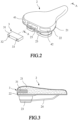
- FIG. 2 is a perspective view showing the laser projection direction-indicating device 3 of the present invention is separated from the saddle 2 and FIG. 3 is a cross-sectional view taken along section A-A of FIG. 2 .
- the saddle 2 that is combined with a laser projection direction-indicating device according to the present invention comprises a saddle body 21 and a base plate 22.
- the saddle 2 is mounted to a seat post of the bicycle 2 by means of the base plate 22, a support base 23, a mounting rack 24, and known installation components (not shown).
- the laser projection direction-indicating device 3 can be of a modularized structure, meaning it includes a module housing 31 mountable to a rear end of the saddle body 21.
- the module housing 31 is received and held in a receiving space 25 of the saddle body 21 or is mounted to the base plate 22 or the support base 23 of the saddle 2.
- a left laser element 32 is disposed in a left laser projection port of the module housing 31; and a right laser element 33 is disposed in a right laser projection port of the module housing 31.
- the left laser projection port points toward a site below a left side of the saddle
- the right laser projection port points toward a site below a right side of the saddle
- optical components such as a collimating lens, a focusing lens, or an optical lens having a pattern or text
- the present invention further comprises a left turn signal light 41, which is arranged at a left-side location of the saddle 2 that is adjacent to the module housing 31; and a right turn signal light 42, which is arranged at a right-side location of the saddle 2 that is adjacent to the module housing 31.
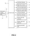
- FIG. 4 shows a diagram of a control circuit according to a first embodiment of the present invention, which comprises a control unit 34 and a direction signal generation unit 35.
- the left laser element 32, the right laser element 33, the left turn signal light 41, and the right turn signal light 42 are all electrically connected with the control unit 34.
- the present invention may further comprise a helmet left side indicator 73, which is arranged at a left-side location of a helmet of a rider of the bicycle 1; and a helmet right side indicator 74, which is arranged at a right-side location of the helmet of the rider of the bicycle 1.
- the control unit 34 transmits a control signal, in a wired or wireless (such as Bluetooth wireless interface) manner, to each of the indicators and lights.
- a sound generation unit 75 may also be connected with the control unit 34.
- the control unit 34 drives the left laser element 32 or the right laser element 33 to generate a laser beam and also simultaneously drives the left turn signal light 41, the right turn signal light 42, the helmet left side indicator 73, or the helmet right side indicator 74 to generate visible light and also optionally has the sound generation unit 75 generating reminder sounds.
Landscapes
- Engineering & Computer Science (AREA)
- Mechanical Engineering (AREA)
- Lighting Device Outwards From Vehicle And Optical Signal (AREA)
Abstract
A saddle (2) having a laser projection direction-indicating device (3) is provided. The laser projection direction-indicating device (3) has a module housing (31) mounted to a saddle body (21). A left laser element (32) is disposed in a left laser projection port of the module housing (31); a right laser element (33) is disposed in a right laser projection port of the module housing (31). A control unit is connected with the left laser element (32) and the right laser element (33). A direction signal generation unit is connected with the control unit and generates a left turn signal or a right turn signal to the control unit. The laser projection direction-indicating device (3) responds to the left turn signal or the right turn signal generated by the direction signal generation unit to have the control unit drive the left laser element (32) or the right laser element (33) to generate a laser projection pattern.
Description
- The present invention relates to a saddle having a direction-change signaling function, and more particularly to a saddle having a laser projection direction-indicating device and a bicycle equipped with the saddle.
- Cycling is now very prevailing, and various accessories have been widely used and have been made professionalized. Concerning the various accessories that are currently available for safety purposes, to improve cycling safety, the manufacturers have developed various alarm lights of different types and functions for being mounted by a user to the front, rear, and lateral sides of a bicycle. There are also products that are available for attaching to the body or head of the rider. However, such attached alarm lights are only developed focusing on differentiation of variation of lighting and light source mounting locations. For the riders, there is still a room for improving the riding safety.
- Although, among the various bicycle accessories for safety purposes, signal lights have been well developed with dynamic operation for left and right turning of a bicycle, yet in practical uses, such known devices are still considered imperfect, and the bicycle rider may easily get a traffic accident when turning with riding on a bicycle.
- Thus, an objective of the present invention is to provide a saddle having a laser projection direction-indicating device and a bicycle equipped with the saddle, in order to provide better safety for a bicyclist riding a bicycle in making left and right turnings to thereby avoid undesired traffic accidents.
- To achieve the above objective, the present invention provides a saddle having a laser projection direction-indicating device, which comprises a module housing mounted to a rear end of the saddle body; a left laser element disposed in a left laser projection port of the module housing; a right laser element disposed in a right laser projection port of the module housing; a control unit connected with the left laser element and the right laser element; and a direction signal generation unit connected with the control unit and is operable to generate one of a left turn signal and a right turn signal to the control unit. The control unit responds to the left turn signal to generate a left-turning driving signal to drive the left laser element to generate a left-side laser projection pattern, which is projected outwards through the left laser projection port; and the control unit responds to the right turn signal to generate a right-turning driving signal to drive the right laser element to generate a right-side laser projection pattern, which is projected outwards through the right laser projection port.
- In efficacy, the saddle according to the present invention is mounted to a bicycle such that the bicycle generates, when making left turning, a left-side laser projection pattern that is projected to a ground surface at a predetermine distance from a left side of the bicycle, and generates, when making right turning, a right-side laser projection pattern that is projected to a ground surface at a predetermine distance from a right side of the bicycle. Further, when generating the left-turning driving signal to drive the left laser element to generate the left-side laser projection pattern, the control unit simultaneously drives a left turn signal light; and when generating the right-turning driving signal to drive the right laser element to generate the right-side laser projection pattern, the control unit simultaneously drives a right turn signal light. By means of the arrangement according to the present invention, enhanced safety is provided for a bicycle making left turning or right turning, in order to avoid traffic accidents. Particularly, the safety of a cyclist may be further enhanced when the bicycle is traveling through a tunnel or a dark site.
- A technical solution adopted in the present invention will be further described with reference to embodiments provided below and the attached drawings.
-
-
FIG. 1 is a schematic view showing a bicycle saddle equipped with a laser projection direction-indicating device according to the present invention; -
FIG. 2 is a perspective view showing a laser projection direction-indicating device of the present invention is separated from a saddle; -
FIG. 3 is a cross-sectional view taken along section A-A ofFIG. 2 ; -
FIG. 4 is a block diagram showing a control circuit according to a first embodiment of the present invention; -
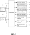
FIG. 5 is a block diagram showing a control circuit according to a second embodiment of the present invention; and -
FIG. 6 is a top plan view showing a bicycle is assisted by the laser projection direction-indicating device according to the present invention to timely project a left-side laser projection pattern or a right-side laser projection pattern for left turning or right turning. - Referring to
FIG. 1 , the present invention provides asaddle 2 of abicycle 1, which is combined with a laser projection direction-indicatingdevice 3, so that when a user rides the bicycle, the laser projection direction-indicatingdevice 3 may generate a laser beam to catch other passersby' attention for enhancing riding safety for the user. - Referring to
FIGS. 2 and 3, FIG. 2 is a perspective view showing the laser projection direction-indicatingdevice 3 of the present invention is separated from thesaddle 2, andFIG. 3 is a cross-sectional view taken along section A-A ofFIG. 2 . As shown in the drawings, thesaddle 2 that is combined with a laser projection direction-indicating device according to the present invention comprises asaddle body 21 and abase plate 22. Thesaddle 2 is mounted to a seat post of thebicycle 2 by means of thebase plate 22, asupport base 23, amounting rack 24, and known installation components (not shown). - In the present invention, the laser projection direction-indicating
device 3 can be of a modularized structure, meaning it includes a module housing 31 mountable to a rear end of thesaddle body 21. Preferably, themodule housing 31 is received and held in areceiving space 25 of thesaddle body 21 or is mounted to thebase plate 22 or thesupport base 23 of thesaddle 2. - A
left laser element 32 is disposed in a left laser projection port of themodule housing 31; and aright laser element 33 is disposed in a right laser projection port of themodule housing 31. In an actual product, the left laser projection port points toward a site below a left side of the saddle, and the right laser projection port points toward a site below a right side of the saddle, and optical components (such as a collimating lens, a focusing lens, or an optical lens having a pattern or text) may be provided in the left laser projection port and the right laser projection port. - The present invention further comprises a left
turn signal light 41, which is arranged at a left-side location of thesaddle 2 that is adjacent to themodule housing 31; and a rightturn signal light 42, which is arranged at a right-side location of thesaddle 2 that is adjacent to themodule housing 31. -
FIG. 4 shows a diagram of a control circuit according to a first embodiment of the present invention, which comprises acontrol unit 34 and a directionsignal generation unit 35. Theleft laser element 32, theright laser element 33, the leftturn signal light 41, and the rightturn signal light 42 are all electrically connected with thecontrol unit 34. The present invention may further comprise a helmetleft side indicator 73, which is arranged at a left-side location of a helmet of a rider of thebicycle 1; and a helmetright side indicator 74, which is arranged at a right-side location of the helmet of the rider of thebicycle 1. Thecontrol unit 34 transmits a control signal, in a wired or wireless (such as Bluetooth wireless interface) manner, to each of the indicators and lights. Asound generation unit 75 may also be connected with thecontrol unit 34. - The direction
signal generation unit 35 is also connected to thecontrol unit 34. The directionsignal generation unit 35 can be a manually-operating switch mounted to for example a predetermined location of a bicycle handlebar. When manually operated by the user, the directionsignal generation unit 35 generates one of a left turn signal S1 and a right turn signal S2 to thecontrol unit 34. - Upon receiving the left turn signal S1 or the right turn signal S2 generated by the direction
signal generation unit 35, thecontrol unit 34 drives theleft laser element 32 or theright laser element 33 to generate a laser beam and also simultaneously drives the leftturn signal light 41, the rightturn signal light 42, the helmetleft side indicator 73, or the helmetright side indicator 74 to generate visible light and also optionally has thesound generation unit 75 generating reminder sounds. -
FIG. 5 shows a diagram of a control circuit according to a second embodiment of the present invention, of which circuit components are generally similar to those of the first embodiment, and thus, identical components are designated with similar reference signs for consistency. In the instant embodiment, avehicle tilt sensor 51 and/or ahandlebar turning sensor 52 is included and connected with thecontrol unit 34. - The
vehicle tilt sensor 51 is mounted to the saddle or aframe 12 of the bicycle or any other location to detect a tilt angle of the bicycle during movement thereof in order to determine whether the bicycle is making left turning or right turning during the movement to thereby generate one of a left turn signal S1 and a right turn signal S2 to thecontrol unit 34. Thehandlebar turning sensor 52 is mounted on a selected location of thebicycle handlebar 11 to detect a turning operation of thebicycle handlebar 11 in order to determine whether the bicycle is taking left turning or right turning to thereby generate one of the left turn signal S1 and the right turn signal S2 to thecontrol unit 34. - Upon receiving the left turn signal S1 or the right turn signal S2 generated by the
vehicle tilt sensor 51 or thehandlebar turning sensor 52, thecontrol unit 34 drives theleft laser element 32 or theright laser element 33 to generate a laser beam and also drives the leftturn signal light 41 or the rightturn signal light 42 to generate visible light. -
FIG. 6 is a top plan view showing thebicycle 1, as being assisted by the laser projection direction-indicatingdevice 3 according to the present invention, timely projects a left-side laser projection pattern or a right-side laser projection pattern for left turning or right turning. - Upon receiving the left turn signal S1 generated by the direction
signal generation unit 35, thevehicle tilt sensor 51, or thehandlebar turning sensor 52, thecontrol unit 34 generates a left-turning driving signal to drive theleft laser element 32 to generate a left-sidelaser projection pattern 61, which is projected through the left laser projection port of themodule housing 31 of the laser projection direction-indicatingdevice 3 to a ground surface at a predetermined distance from a left side of thebicycle 1, and simultaneously, thecontrol unit 34 drives the leftturn signal light 41 to generate visible light to catch the attention of other passersby at a rear side or left side of the bicycle. Optionally, aleft turn indicator 71 may be mounted to the bicycle at other locations (such as a left-side end of the handlebar or a left side of the frame) to further improve riding safety. - Upon receiving the right turn signal S2 generated by the direction
signal generation unit 35, thevehicle tilt sensor 51, or thehandlebar turning sensor 52, thecontrol unit 34 generates a right-turning driving signal to drive theright laser element 33 to generate a right-sidelaser projection pattern 62, which is projected through the right laser projection port of themodule housing 31 of the laser projection direction-indicatingdevice 3 to a ground surface at a predetermined distance from a right side of thebicycle 1, and simultaneously, thecontrol unit 34 drives the rightturn signal light 42 to generate visible light to catch the attention of other passersby at a rear side or right side of the bicycle. Optionally, aright turn indicator 72 may be mounted to the bicycle at other locations (such as a right-side end of the handlebar or a right side of the frame) to further improve riding safety. - The left-side
laser projection pattern 61 and the right-sidelaser projection pattern 62 as discussed above are each formed, in an example, as a light spot for implementation of laser projection pattern, and in an actual product, it can be made as a pattern of other shapes (such as a crisscross pattern, a straight line pattern, a pattern carrying characters, and a pattern carrying a figure). - The embodiments provided above are implemented by taking a saddle of a bicycle as an example for explanation and illustration. In practical applications, the present invention is applicable to other transportation tools, such as an electric bicycle, an electric walk-substituting vehicle, an electric scooter, an electrically-assisted bicycle, and an electric shopping cart.
Claims (10)
- A saddle (2) having a base plate (22) and a saddle body (21) supported on the base plate (22), the saddle (2) being provided with a laser projection direction-indicating device (3), characterized in that the laser projection direction-indicating device (3) comprises:a module housing (31) mounted to a rear end of the saddle body (21) of the saddle (2);a left laser element (32) disposed in a left laser projection port of the module housing (31);a right laser element (33) disposed in a right laser projection port of the module housing (31);a control unit (34) connected with the left laser element (32) and the right laser element (33); anda direction signal generation unit (35) connected with the control unit (34) and operable to generate one of a left turn signal (S1) and a right turn signal (S2) to the control unit (34);wherein the control unit (34) responds to the left turn signal (S1) to generate a left-turning driving signal to drive the left laser element (32) to project a left-side laser projection pattern (61); andthe control unit (34) responds to the right turn signal (S2) to generate a right-turning driving signal to drive the right laser element (33) to project a right-side laser projection pattern (62).
- The saddle (2) according to claim 1, wherein the module housing (31) is disposed in a receiving space (25) formed in the saddle body (21) or onto the base plate (22).
- The saddle (2) according to claim 1, further comprising:a left turn signal light (41) arranged at a left-side location of the saddle (2) that is adjacent to the module housing (31), so that the control unit (34), when generating the left-turning driving signal to drive the left laser element (32) to generate the left-side laser projection pattern (61), simultaneously drives the left turn signal light (41); anda right turn signal light (42) arranged at a right-side location of the saddle (2) that is adjacent to the module housing (31), so that the control unit (34), when generating the right-turning driving signal to drive the right laser element (33) to generate the right-side laser projection pattern (62), simultaneously drives the right turn signal light (42).
- The saddle (2) according to claim 1, wherein the direction signal generation unit (35) comprises one of a manually-operated switch and a vehicle tilt sensor (51), which is operable to generate the left turn signal (S1) or the right turn signal (S2).
- A bicycle (1) provided with a saddle (2) having a base plate (22) and a saddle body (21) supported on the base plate (22), the saddle (2) being mounted to a seat post of the bicycle (1), characterized in that the bicycle (1) is provided with a laser projection direction-indicating device (3) which comprises:a module housing (31) mounted to a rear end of the saddle body (21);a left laser element (32) disposed in a left laser projection port of the module housing (31);a right laser element (33) disposed in a right laser projection port of the module housing (31);a control unit (34) connected with the left laser element (32) and the right laser element (33); anda direction signal generation unit (35) connected with the control unit (34) and operable to generate one of a left turn signal (S1) and a right turn signal (S2) to the control unit (34);wherein the control unit (34) responds to the left turn signal (S1) to generate a left-turning driving signal to drive the left laser element (32) to generate a left-side laser projection pattern (61), which is projected toward a ground surface at a predetermined distance from a left side of the bicycle (1); andthe control unit (34) responds to the right turn signal (S2) to generate a right-turning driving signal to drive the right laser element (33) to generate a right-side laser projection pattern (62), which is projected toward a ground surface at a predetermined distance from a right side of the bicycle (1).
- The bicycle (1) according to claim 5, wherein the module housing (31) is disposed in a receiving space (25) formed in the saddle body (21) or onto the base plate (22).
- The bicycle (1) according to claim 5, further comprising:a left turn signal light (41) arranged at a left-side location of the saddle (2) that is adjacent to the module housing (31), so that the control unit (34), when generating the left-turning driving signal to drive the left laser element (32) to generate the left-side laser projection pattern (61), simultaneously drives the left turn signal light (41); anda right turn signal light (42) arranged at a right-side location of the saddle (2) that is adjacent to the module housing (31), so that the control unit (34), when generating the right-turning driving signal to drive the right laser element (33) to generate the right-side laser projection pattern (62), simultaneously drives the right turn signal light (42).
- The bicycle (1) according to claim 5, further comprising:a left turn indicator (71) mounted to a left-side location of one of a bicycle handlebar (11) and a frame (12), so that the control unit (34), when generating the left-turning driving signal to drive the left laser element (32) to generate the left-side laser projection pattern (61), simultaneously drives the left turn indicator (71); anda right turn indicator (72) mounted to a right-side location of one of the bicycle handlebar (11) and the frame (12), so that the control unit (34), when generating the right-turning driving signal to drive the right laser element (33) to generate the right-side laser projection pattern (62), simultaneously drives the right turn indicator (72).
- The bicycle (1) according to claim 5, further comprising:a helmet left side indicator (73) arranged at a left-side location of a helmet, so that the control unit (34), when generating the left-turning driving signal to drive the left laser element (32) to generate the left-side laser projection pattern (61), simultaneously drives the helmet left side indicator (73); anda helmet right side indicator (74) arranged at a right-side location of the helmet, so that the control unit (34), when generating the right-turning driving signal to drive the right laser element (33) to generate the right-side laser projection pattern (62), simultaneously drives the helmet right side indicator (74).
- The bicycle (1) according to claim 5, wherein the direction signal generation unit (35) comprises one of a manually-operated switch, a vehicle tilt sensor (51), and a handlebar turning sensor (52), which is operable to generate the left turn signal (S1) or the right turn signal (S2).
Applications Claiming Priority (1)
| Application Number | Priority Date | Filing Date | Title |
|---|---|---|---|
| TW112209919U TWM652580U (en) | 2023-09-14 | 2023-09-14 | Seat cushion with laser projection pointing device and bicycle having the same |
Publications (1)
| Publication Number | Publication Date |
|---|---|
| EP4524007A1 true EP4524007A1 (en) | 2025-03-19 |
Family
ID=88315671
Family Applications (1)
| Application Number | Title | Priority Date | Filing Date |
|---|---|---|---|
| EP23202581.7A Withdrawn EP4524007A1 (en) | 2023-09-14 | 2023-10-10 | Saddle having laser projection direction-indicating device and bicycle equipped with the saddle |
Country Status (3)
| Country | Link |
|---|---|
| US (1) | US12116073B1 (en) |
| EP (1) | EP4524007A1 (en) |
| TW (1) | TWM652580U (en) |
Citations (6)
| Publication number | Priority date | Publication date | Assignee | Title |
|---|---|---|---|---|
| US20100134272A1 (en) * | 2008-12-03 | 2010-06-03 | Palacios Alfred J | Helmet Providing Driving Instructional Signals |
| CN202368719U (en) * | 2011-12-27 | 2012-08-08 | 东莞市玄天电子有限公司 | Bicycle laser warning light |
| KR101240614B1 (en) * | 2010-06-14 | 2013-03-06 | 진홍규 | Bicycle with guide lamp |
| US20170183050A1 (en) * | 2015-12-28 | 2017-06-29 | Urbs International L.L.C. | Bike saddle with illumination-controlled lights |
| US10086894B2 (en) * | 2015-09-08 | 2018-10-02 | Brake Free Technologies | Safety device |
| US20230043927A1 (en) * | 2021-08-04 | 2023-02-09 | Chuanqi Liu | Container Saddle |
Family Cites Families (4)
| Publication number | Priority date | Publication date | Assignee | Title |
|---|---|---|---|---|
| US5561414A (en) * | 1995-02-22 | 1996-10-01 | Yu Hsiang Chiu Enterprise Co., Ltd. | Bicycle warning signal control device |
| US8269619B2 (en) * | 2009-09-10 | 2012-09-18 | Abocom Systems, Inc. | Wireless light indication and control device |
| US10611422B2 (en) * | 2016-11-10 | 2020-04-07 | Michael Kerbel | Systems, methods and techniques for intelligent accessories |
| US20200039594A1 (en) * | 2017-08-25 | 2020-02-06 | Daniel Ebrahemi | Peripheral ground projected signal illumination for vehicle |
-
2023
- 2023-09-14 TW TW112209919U patent/TWM652580U/en unknown
- 2023-10-03 US US18/479,941 patent/US12116073B1/en active Active
- 2023-10-10 EP EP23202581.7A patent/EP4524007A1/en not_active Withdrawn
Patent Citations (6)
| Publication number | Priority date | Publication date | Assignee | Title |
|---|---|---|---|---|
| US20100134272A1 (en) * | 2008-12-03 | 2010-06-03 | Palacios Alfred J | Helmet Providing Driving Instructional Signals |
| KR101240614B1 (en) * | 2010-06-14 | 2013-03-06 | 진홍규 | Bicycle with guide lamp |
| CN202368719U (en) * | 2011-12-27 | 2012-08-08 | 东莞市玄天电子有限公司 | Bicycle laser warning light |
| US10086894B2 (en) * | 2015-09-08 | 2018-10-02 | Brake Free Technologies | Safety device |
| US20170183050A1 (en) * | 2015-12-28 | 2017-06-29 | Urbs International L.L.C. | Bike saddle with illumination-controlled lights |
| US20230043927A1 (en) * | 2021-08-04 | 2023-02-09 | Chuanqi Liu | Container Saddle |
Also Published As
| Publication number | Publication date |
|---|---|
| US12116073B1 (en) | 2024-10-15 |
| TWM652580U (en) | 2024-03-11 |
Similar Documents
| Publication | Publication Date | Title |
|---|---|---|
| US8325027B2 (en) | Safety light device | |
| CN101801772B (en) | straddle vehicle | |
| US20200207435A1 (en) | Bicycle with integrated electronic components | |
| US10906603B2 (en) | Bicycle | |
| JP4821093B2 (en) | Vehicle equipment | |
| JP7411684B2 (en) | Rider support system and rider support system control method | |
| US7607504B2 (en) | Motorcycle | |
| JP6873070B2 (en) | Saddle-type vehicle lighting device layout structure | |
| EP3508406B1 (en) | Saddle-type vehicle | |
| EP4524007A1 (en) | Saddle having laser projection direction-indicating device and bicycle equipped with the saddle | |
| JP7364446B2 (en) | Rider support system and rider support system control method | |
| JP2006235807A (en) | Vehicle recognition device | |
| KR20110136540A (en) | Bicycle back and forth device | |
| JP2010149676A (en) | Accessory mounting device for bicycle | |
| JP2017039488A (en) | Lean vehicle | |
| EP4330939A1 (en) | System and method to improve road safety | |
| JP2010149577A (en) | Coaxial motorcycle | |
| CN214356446U (en) | Vibration warning device with tilt offset for motorcycle | |
| US12435854B1 (en) | Bicycle steering prompt system | |
| TW201910173A (en) | Direction-indicating warning light device for bicycle capable of projecting a warning signal toward the ground along with the steering of a bicycle | |
| EP4628393A1 (en) | Bicycle steering prompt system | |
| JP3245760U (en) | Saddle with radar device to detect nearby objects and issue an alarm | |
| US20250019023A1 (en) | Auxiliary lighting device for a two-wheeler and two-wheeler with the same | |
| JP6461753B2 (en) | Saddle riding | |
| TWI891284B (en) | Bicycle Turn Signal System |
Legal Events
| Date | Code | Title | Description |
|---|---|---|---|
| PUAI | Public reference made under article 153(3) epc to a published international application that has entered the european phase |
Free format text: ORIGINAL CODE: 0009012 |
|
| STAA | Information on the status of an ep patent application or granted ep patent |
Free format text: STATUS: THE APPLICATION HAS BEEN PUBLISHED |
|
| AK | Designated contracting states |
Kind code of ref document: A1 Designated state(s): AL AT BE BG CH CY CZ DE DK EE ES FI FR GB GR HR HU IE IS IT LI LT LU LV MC ME MK MT NL NO PL PT RO RS SE SI SK SM TR |
|
| STAA | Information on the status of an ep patent application or granted ep patent |
Free format text: STATUS: THE APPLICATION IS DEEMED TO BE WITHDRAWN |
|
| 18D | Application deemed to be withdrawn |
Effective date: 20250920 |