EP4523938A1 - Electric crawler vehicle - Google Patents
Electric crawler vehicle Download PDFInfo
- Publication number
- EP4523938A1 EP4523938A1 EP24198564.7A EP24198564A EP4523938A1 EP 4523938 A1 EP4523938 A1 EP 4523938A1 EP 24198564 A EP24198564 A EP 24198564A EP 4523938 A1 EP4523938 A1 EP 4523938A1
- Authority
- EP
- European Patent Office
- Prior art keywords
- electric motor
- traveling
- turning
- electric
- speed reducer
- Prior art date
- Legal status (The legal status is an assumption and is not a legal conclusion. Google has not performed a legal analysis and makes no representation as to the accuracy of the status listed.)
- Pending
Links
Images


Classifications
-
- B—PERFORMING OPERATIONS; TRANSPORTING
- B60—VEHICLES IN GENERAL
- B60K—ARRANGEMENT OR MOUNTING OF PROPULSION UNITS OR OF TRANSMISSIONS IN VEHICLES; ARRANGEMENT OR MOUNTING OF PLURAL DIVERSE PRIME-MOVERS IN VEHICLES; AUXILIARY DRIVES FOR VEHICLES; INSTRUMENTATION OR DASHBOARDS FOR VEHICLES; ARRANGEMENTS IN CONNECTION WITH COOLING, AIR INTAKE, GAS EXHAUST OR FUEL SUPPLY OF PROPULSION UNITS IN VEHICLES
- B60K1/00—Arrangement or mounting of electrical propulsion units
- B60K1/02—Arrangement or mounting of electrical propulsion units comprising more than one electric motor
-
- B—PERFORMING OPERATIONS; TRANSPORTING
- B62—LAND VEHICLES FOR TRAVELLING OTHERWISE THAN ON RAILS
- B62D—MOTOR VEHICLES; TRAILERS
- B62D11/00—Steering non-deflectable wheels; Steering endless tracks or the like
- B62D11/02—Steering non-deflectable wheels; Steering endless tracks or the like by differentially driving ground-engaging elements on opposite vehicle sides
- B62D11/06—Steering non-deflectable wheels; Steering endless tracks or the like by differentially driving ground-engaging elements on opposite vehicle sides by means of a single main power source
- B62D11/10—Steering non-deflectable wheels; Steering endless tracks or the like by differentially driving ground-engaging elements on opposite vehicle sides by means of a single main power source using gearings with differential power outputs on opposite sides, e.g. twin-differential or epicyclic gears
-
- B—PERFORMING OPERATIONS; TRANSPORTING
- B62—LAND VEHICLES FOR TRAVELLING OTHERWISE THAN ON RAILS
- B62D—MOTOR VEHICLES; TRAILERS
- B62D55/00—Endless track vehicles
- B62D55/08—Endless track units; Parts thereof
- B62D55/12—Arrangement, location, or adaptation of driving sprockets
- B62D55/125—Final drives
-
- B—PERFORMING OPERATIONS; TRANSPORTING
- B60—VEHICLES IN GENERAL
- B60K—ARRANGEMENT OR MOUNTING OF PROPULSION UNITS OR OF TRANSMISSIONS IN VEHICLES; ARRANGEMENT OR MOUNTING OF PLURAL DIVERSE PRIME-MOVERS IN VEHICLES; AUXILIARY DRIVES FOR VEHICLES; INSTRUMENTATION OR DASHBOARDS FOR VEHICLES; ARRANGEMENTS IN CONNECTION WITH COOLING, AIR INTAKE, GAS EXHAUST OR FUEL SUPPLY OF PROPULSION UNITS IN VEHICLES
- B60K1/00—Arrangement or mounting of electrical propulsion units
-
- B—PERFORMING OPERATIONS; TRANSPORTING
- B60—VEHICLES IN GENERAL
- B60K—ARRANGEMENT OR MOUNTING OF PROPULSION UNITS OR OF TRANSMISSIONS IN VEHICLES; ARRANGEMENT OR MOUNTING OF PLURAL DIVERSE PRIME-MOVERS IN VEHICLES; AUXILIARY DRIVES FOR VEHICLES; INSTRUMENTATION OR DASHBOARDS FOR VEHICLES; ARRANGEMENTS IN CONNECTION WITH COOLING, AIR INTAKE, GAS EXHAUST OR FUEL SUPPLY OF PROPULSION UNITS IN VEHICLES
- B60K17/00—Arrangement or mounting of transmissions in vehicles
- B60K17/04—Arrangement or mounting of transmissions in vehicles characterised by arrangement, location or kind of gearing
- B60K17/043—Transmission unit disposed in on near the vehicle wheel, or between the differential gear unit and the wheel
- B60K17/046—Transmission unit disposed in on near the vehicle wheel, or between the differential gear unit and the wheel with planetary gearing having orbital motion
-
- B—PERFORMING OPERATIONS; TRANSPORTING
- B60—VEHICLES IN GENERAL
- B60K—ARRANGEMENT OR MOUNTING OF PROPULSION UNITS OR OF TRANSMISSIONS IN VEHICLES; ARRANGEMENT OR MOUNTING OF PLURAL DIVERSE PRIME-MOVERS IN VEHICLES; AUXILIARY DRIVES FOR VEHICLES; INSTRUMENTATION OR DASHBOARDS FOR VEHICLES; ARRANGEMENTS IN CONNECTION WITH COOLING, AIR INTAKE, GAS EXHAUST OR FUEL SUPPLY OF PROPULSION UNITS IN VEHICLES
- B60K17/00—Arrangement or mounting of transmissions in vehicles
- B60K17/04—Arrangement or mounting of transmissions in vehicles characterised by arrangement, location or kind of gearing
- B60K17/06—Arrangement or mounting of transmissions in vehicles characterised by arrangement, location or kind of gearing of change-speed gearing
-
- B—PERFORMING OPERATIONS; TRANSPORTING
- B60—VEHICLES IN GENERAL
- B60K—ARRANGEMENT OR MOUNTING OF PROPULSION UNITS OR OF TRANSMISSIONS IN VEHICLES; ARRANGEMENT OR MOUNTING OF PLURAL DIVERSE PRIME-MOVERS IN VEHICLES; AUXILIARY DRIVES FOR VEHICLES; INSTRUMENTATION OR DASHBOARDS FOR VEHICLES; ARRANGEMENTS IN CONNECTION WITH COOLING, AIR INTAKE, GAS EXHAUST OR FUEL SUPPLY OF PROPULSION UNITS IN VEHICLES
- B60K17/00—Arrangement or mounting of transmissions in vehicles
- B60K17/28—Arrangement or mounting of transmissions in vehicles characterised by arrangement, location, or type of power take-off
-
- B—PERFORMING OPERATIONS; TRANSPORTING
- B60—VEHICLES IN GENERAL
- B60K—ARRANGEMENT OR MOUNTING OF PROPULSION UNITS OR OF TRANSMISSIONS IN VEHICLES; ARRANGEMENT OR MOUNTING OF PLURAL DIVERSE PRIME-MOVERS IN VEHICLES; AUXILIARY DRIVES FOR VEHICLES; INSTRUMENTATION OR DASHBOARDS FOR VEHICLES; ARRANGEMENTS IN CONNECTION WITH COOLING, AIR INTAKE, GAS EXHAUST OR FUEL SUPPLY OF PROPULSION UNITS IN VEHICLES
- B60K25/00—Auxiliary drives
-
- B—PERFORMING OPERATIONS; TRANSPORTING
- B62—LAND VEHICLES FOR TRAVELLING OTHERWISE THAN ON RAILS
- B62D—MOTOR VEHICLES; TRAILERS
- B62D11/00—Steering non-deflectable wheels; Steering endless tracks or the like
- B62D11/02—Steering non-deflectable wheels; Steering endless tracks or the like by differentially driving ground-engaging elements on opposite vehicle sides
- B62D11/06—Steering non-deflectable wheels; Steering endless tracks or the like by differentially driving ground-engaging elements on opposite vehicle sides by means of a single main power source
- B62D11/10—Steering non-deflectable wheels; Steering endless tracks or the like by differentially driving ground-engaging elements on opposite vehicle sides by means of a single main power source using gearings with differential power outputs on opposite sides, e.g. twin-differential or epicyclic gears
- B62D11/14—Steering non-deflectable wheels; Steering endless tracks or the like by differentially driving ground-engaging elements on opposite vehicle sides by means of a single main power source using gearings with differential power outputs on opposite sides, e.g. twin-differential or epicyclic gears differential power outputs being effected by additional power supply to one side, e.g. power originating from secondary power source
- B62D11/16—Steering non-deflectable wheels; Steering endless tracks or the like by differentially driving ground-engaging elements on opposite vehicle sides by means of a single main power source using gearings with differential power outputs on opposite sides, e.g. twin-differential or epicyclic gears differential power outputs being effected by additional power supply to one side, e.g. power originating from secondary power source the additional power supply being supplied mechanically
-
- B—PERFORMING OPERATIONS; TRANSPORTING
- B62—LAND VEHICLES FOR TRAVELLING OTHERWISE THAN ON RAILS
- B62D—MOTOR VEHICLES; TRAILERS
- B62D5/00—Power-assisted or power-driven steering
- B62D5/04—Power-assisted or power-driven steering electrical, e.g. using an electric servo-motor connected to, or forming part of, the steering gear
- B62D5/0403—Power-assisted or power-driven steering electrical, e.g. using an electric servo-motor connected to, or forming part of, the steering gear characterised by constructional features, e.g. common housing for motor and gear box
-
- B—PERFORMING OPERATIONS; TRANSPORTING
- B62—LAND VEHICLES FOR TRAVELLING OTHERWISE THAN ON RAILS
- B62D—MOTOR VEHICLES; TRAILERS
- B62D55/00—Endless track vehicles
- B62D55/06—Endless track vehicles with tracks without ground wheels
- B62D55/065—Multi-track vehicles, i.e. more than two tracks
-
- B—PERFORMING OPERATIONS; TRANSPORTING
- B62—LAND VEHICLES FOR TRAVELLING OTHERWISE THAN ON RAILS
- B62D—MOTOR VEHICLES; TRAILERS
- B62D55/00—Endless track vehicles
- B62D55/32—Assembly, disassembly, repair or servicing of endless-track systems
-
- B—PERFORMING OPERATIONS; TRANSPORTING
- B60—VEHICLES IN GENERAL
- B60Y—INDEXING SCHEME RELATING TO ASPECTS CROSS-CUTTING VEHICLE TECHNOLOGY
- B60Y2200/00—Type of vehicle
- B60Y2200/20—Off-Road Vehicles
- B60Y2200/25—Track vehicles
-
- B—PERFORMING OPERATIONS; TRANSPORTING
- B60—VEHICLES IN GENERAL
- B60Y—INDEXING SCHEME RELATING TO ASPECTS CROSS-CUTTING VEHICLE TECHNOLOGY
- B60Y2304/00—Optimising design; Manufacturing; Testing
- B60Y2304/01—Minimizing space with more compact designs or arrangements
-
- B—PERFORMING OPERATIONS; TRANSPORTING
- B60—VEHICLES IN GENERAL
- B60Y—INDEXING SCHEME RELATING TO ASPECTS CROSS-CUTTING VEHICLE TECHNOLOGY
- B60Y2304/00—Optimising design; Manufacturing; Testing
- B60Y2304/07—Facilitating assembling or mounting
-
- B—PERFORMING OPERATIONS; TRANSPORTING
- B60—VEHICLES IN GENERAL
- B60Y—INDEXING SCHEME RELATING TO ASPECTS CROSS-CUTTING VEHICLE TECHNOLOGY
- B60Y2304/00—Optimising design; Manufacturing; Testing
- B60Y2304/07—Facilitating assembling or mounting
- B60Y2304/074—Facilitating assembling or mounting by improved accessibility
-
- B—PERFORMING OPERATIONS; TRANSPORTING
- B60—VEHICLES IN GENERAL
- B60Y—INDEXING SCHEME RELATING TO ASPECTS CROSS-CUTTING VEHICLE TECHNOLOGY
- B60Y2410/00—Constructional features of vehicle sub-units
- B60Y2410/10—Housings
-
- B—PERFORMING OPERATIONS; TRANSPORTING
- B62—LAND VEHICLES FOR TRAVELLING OTHERWISE THAN ON RAILS
- B62D—MOTOR VEHICLES; TRAILERS
- B62D11/00—Steering non-deflectable wheels; Steering endless tracks or the like
- B62D11/001—Steering non-deflectable wheels; Steering endless tracks or the like control systems
- B62D11/003—Electric or electronic control systems
-
- B—PERFORMING OPERATIONS; TRANSPORTING
- B62—LAND VEHICLES FOR TRAVELLING OTHERWISE THAN ON RAILS
- B62D—MOTOR VEHICLES; TRAILERS
- B62D11/00—Steering non-deflectable wheels; Steering endless tracks or the like
- B62D11/02—Steering non-deflectable wheels; Steering endless tracks or the like by differentially driving ground-engaging elements on opposite vehicle sides
- B62D11/06—Steering non-deflectable wheels; Steering endless tracks or the like by differentially driving ground-engaging elements on opposite vehicle sides by means of a single main power source
- B62D11/10—Steering non-deflectable wheels; Steering endless tracks or the like by differentially driving ground-engaging elements on opposite vehicle sides by means of a single main power source using gearings with differential power outputs on opposite sides, e.g. twin-differential or epicyclic gears
- B62D11/14—Steering non-deflectable wheels; Steering endless tracks or the like by differentially driving ground-engaging elements on opposite vehicle sides by means of a single main power source using gearings with differential power outputs on opposite sides, e.g. twin-differential or epicyclic gears differential power outputs being effected by additional power supply to one side, e.g. power originating from secondary power source
Definitions
- the present invention relates to an electric crawler vehicle.
- Patent Document 1 Japanese Unexamined Patent Publication No. 2001-271317
- the width of the drive unit includes a width corresponding to the sum of the axial dimensions of the two electric motors. Therefore, in the crawler vehicle including the aforementioned drive unit, there is a limitation in setting of an inter-center dimension (tread) between the left and right traveling crawlers. As a result, there is a concern that the number of operations that can be performed is reduced. For example, depending on an agricultural work, the tread needs to be set narrow, but in the configuration in which the electric motors are aligned in the left-right direction, the tread becomes wider, and predetermined agricultural work cannot be coped with any more in some cases.
- the present invention was made in order to solve the aforementioned problems, and an object thereof is to provide an electric crawler vehicle capable of facilitating works of the maintenance of a plurality of electric motors and assembling to the vehicle and of improving a degree of freedom in setting a tread.
- An electric crawler vehicle includes a pair of left and right traveling crawlers, a traveling electric motor that generates traveling power to be transmitted to the pair of left and right traveling crawlers, and a turning electric motor that generates turning power to be transmitted to the pair of left and right traveling crawlers, and the traveling electric motor and the turning electric motor are disposed on one lateral side of the vehicle.
- the works of the maintenance of the plurality of electric motors (the traveling electric motor and the turning electric motor) and of the assembling to the vehicle can be facilitated, and the degree of freedom in setting the tread can be improved.
- FIG. 1 is a left side view illustrating a schematic configuration of an electric crawler 1, which is an example of an electric crawler vehicle of this Embodiment.
- FIG. 2 is a right side view illustrating a schematic configuration of the electric crawler 1. Note that the electric crawler 1 may be simply referred to as a vehicle in the following.
- a direction in which an operator (manipulator, driver) seated on a driver's seat 11 of the electric crawler 1 faces forward is defined as a front, and a direction opposite thereto is defined as a rear.
- the left side as viewed from the operator seated on the driver's seat 11 is referred to as "left” and the right side as “right”, respectively.
- a gravity direction perpendicular to a front-rear direction and a left-right direction is defined as an up-down direction
- an upstream side in the gravity direction is defined as "up”
- a downstream side is defined as "down”.
- the electric crawler 1 is a crawler type tractor including traveling crawlers 2 on left and right.
- Each of the traveling crawlers 2 includes a track frame 3 extending in the front-rear direction.
- a front-side idler 4a is rotatably supported, and on a rear end part, a rear-side idler 4b is rotatably supported.
- a plurality of rolling wheels 5 are rotatably supported between the front-side idler 4a and the rear-side idler 4b.
- a drive sprocket 6 is disposed as a drive wheel.
- a crawler belt 7 is wound around the drive sprocket 6, the front-side idler 4a, the rear-side idler 4b, and the plurality of rolling wheels 5 to constitute the traveling crawler 2.
- the electric crawler 1 includes a pair of left and right traveling crawlers 2, each having a drive wheel (drive sprocket 6).
- the electric crawler 1 includes a main body frame 10.
- the aforementioned track frame 3 is positioned below a main body frame 10 and is connected to the main body frame 10.
- the driver's seat 11 is disposed above the main body frame 10 via a seat mount 11a.
- a safety frame 12 is erected on the rear of the driver's seat 11.
- a first battery unit 13a is disposed in a space between the main body frame 10 and the driver's seat 11.
- a second battery unit 13b is disposed above the main body frame 10 and on the rear of the safety frame 12.
- Electronic components such as a system controller 56 (see FIG. 6 ) to be described later are disposed above the second battery unit 13b.
- the first battery unit 13a and the second battery unit 13b are collectively referred to also as a battery unit 13 below.
- a floor (not shown) is provided on the front below the driver's seat 11.
- the floor is supported by the main body frame 10.
- a steering unit 14 is provided on the front side of the floor.
- a lever for switching between forward and backward movement of the vehicle in addition to a steering wheel 15 for turning the vehicle, a lever for switching between forward and backward movement of the vehicle, a Power Take Off (PTO) switching lever, a brake pedal, and the like are provided.
- PTO Power Take Off
- a first speed reducer 21 is disposed between the pair of left and right traveling crawlers 2.
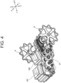
- FIG. 3 is a perspective view of the first speed reducer 21.
- FIG. 4 is a perspective view of an inside of the first speed reducer 21.
- a traveling electric motor M1 and a turning electric motor M2 are connected to the first speed reducer 21.
- the traveling electric motor M1 is positioned on the front of the turning electric motor M2.
- a plurality of gears and chains or belts are provided between the drive shaft of the traveling electric motor M1 and the drive shafts of the left and right traveling crawlers 2.
- the traveling power generated by the traveling electric motor M1 is transmitted to the drive shafts of the left and right traveling crawlers 2 by the plurality of gears and the chain or the belt.
- the plurality of gears are provided between the drive shaft of the turning electric motor M2 and the drive shafts of the left and right traveling crawlers 2, and turning power generated by the turning electric motor M2 is transmitted to the drive shafts of the left and right traveling crawlers 2 by the plurality of gears.
- the aforementioned drive sprockets 6 are provided at both left and right ends of the drive shafts of the left and right traveling crawlers 2. The drive sprocket 6 is rotated by the traveling power or the turning power transmitted to the drive shaft, whereby the left and right traveling crawlers 2 are rotated, and the electric crawler 1 travels or turns.
- the electric crawler 1 includes a differential mechanism 30 (see FIG. 5 ), and details of the differential mechanism 30 will be described later.
- the electric crawler 1 of this Embodiment includes the traveling electric motor M1 that generates traveling power to be transmitted to the pair of left and right traveling crawlers 2, and the turning electric motor M2 that generates turning power to be transmitted to the pair of left and right traveling crawlers 2.
- the second speed reducer 22 is a PTO speed reducer to which the PTO electric motor M3 is assembled.
- the second speed reducer 22 and the work machine 24 are connected to each other via a PTO power transmission unit 25 (see FIG. 2 ).
- the work machine 24 can be driven by transmitting the power of the PTO electric motor M3 to the work machine 24 via the second speed reducer 22 and the PTO power transmission unit 25.
- a ring gear 36 is disposed concentrically with the aforementioned sun shaft 33.
- Each ring gear 36 has internal teeth on its inner peripheral surface and external teeth on its outer peripheral surface.
- the ring gear 36 of the left-side planetary transmission mechanism 31 is disposed such that the internal teeth thereof mesh with the plurality of left-side planetary gears 34.
- the ring gear 36 of the right-side planetary transmission mechanism 31 is disposed such that the internal teeth thereof mesh with the plurality of right-side planetary gears 34.
- Each of the ring gears 36 is rotatably supported on the sun shaft 33 or on the drive shafts 6a and 6b via bearings.
- the left-side transmission gear 37a is disposed so as to directly mesh with external teeth of the left-side ring gear 36.
- the right-side transmission gear 37b is disposed so as to mesh with a reverse gear 39 attached to a reversing shaft 38.
- This reverse gear 39 is disposed so as to mesh with the outer teeth of the right-side ring gear 36.
- the sun shaft 33 and the sun gears 35 on both the left and right sides are fixed. Therefore, when the turning electric motor M2 (motor-output shaft 37) is rotated in the forward direction, the left-side ring gear 36 rotates in the reverse direction by a predetermined number of rotations (rotational speed), and the right-side ring gear 36 rotates in the forward direction at the same number of rotations as the left-side ring gear 36.
- the planetary gear 34 and the planetary carrier 32 on the left side rotate reversely about the sun shaft 33, while the planetary gear 34 and the planetary carrier 32 on the right side rotate forward about the sun shaft 33.
- the drive shaft 6a coaxial with the left-side planetary carrier 32 rotates in the reverse direction, while the drive shaft 6b coaxial with the right-side planetary carrier 32 rotates in the forward direction.
- the left-side traveling crawler 2 moves backward, and the right-side traveling crawler 2 moves forward.
- the electric crawler 1 spins and turns to the left on the spot.
- the traveling electric motor M1 when the traveling electric motor M1 is rotated, the rotational power (traveling power) of the traveling electric motor M1 is transmitted to the sun shaft 33 via the traveling power transmission unit Q.
- the traveling power transmission unit Q is configured to include a plurality of gears, a belt, and the like.
- the turning electric motor M2 is stopped in advance, for example, the rotation of the ring gears 36 on both the left and right sides is stopped and is brought into a fixed state. Therefore, the traveling power transmitted to the sun shaft 33 is equally transmitted to the left-side drive shaft 6a and the right-side drive shaft 6b via the left and right planetary transmission mechanisms 31 (the sun gears 35, the planetary gears 34, and the planetary carriers 32).
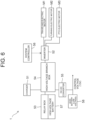
- FIG. 6 is a block diagram schematically illustrating a configuration of the control system of the electric crawler 1. Note that, in FIG. 6 , a solid line indicates a power supply path, and a broken line indicates a signal path.
- the electric crawler 1 includes a charger 51, an inverter 52, a relay box 53, a high-voltage branch box 54, a DC-DC converter 55, a system controller 56, a high-voltage battery 57, and a lead battery (12V battery) 58, in addition to the traveling electric motor M1, the turning electric motor M2, and the PTO electric motor M3 described above.
- the traveling electric motor M1, the turning electric motor M2, and the PTO electric motor M3 are driven by electric power supplied from the high-voltage battery 57 via the relay box 53, the high-voltage branch box 54, and the inverter 52.
- the relay box 53 is a battery control unit that configured to include a battery relay and a fuse, and controls the battery relay so as to control an input and an output of the high-voltage battery 57.
- the high-voltage branch box 54 is configured to include a charger relay, an inverter relay, a fuse, and the like. The voltage output from the aforementioned charger 51 is supplied to the high-voltage battery 57 via the high-voltage branch box 54 and the relay box 53. As a result, the high-voltage battery 57 can be charged. The voltage output from the high-voltage battery 57 is supplied to the inverter 52 via the relay box 53 and the high-voltage branch box 54.
- the traveling electric motor M1 and the turning electric motor M2 are positioned side by side in a direction perpendicular to the vehicle width direction (the front-rear direction of the electric crawler 1). In this Embodiment, the traveling electric motor M1 and the turning electric motor M2 are positioned side by side in the front-rear direction of the vehicle.
- both the traveling electric motor M1 and the turning electric motor M2 can be easily accessed from the same one lateral side (from one side). Further, when the traveling electric motor M1 and the turning electric motor M2 are to be assembled to the vehicle at the manufacture of the electric crawler 1, both the traveling electric motor M1 and the turning electric motor M2 can be assembled from the same one lateral side to the vehicle.
- the traveling electric motor M1, the turning electric motor M2, and the first speed reducer 21 are regarded as one drive portion DP (mechanism), as shown in FIG. 8 , the dimension in the width direction of the drive portion DP is equal to the dimension in the axial direction of the traveling electric motor M1 + the thickness of the first speed reducer 21 or the dimension in the axial direction of the turning electric motor M2 + the thickness of the first speed reducer 21. That is, the electric motor contributing to the dimension in the width direction of the drive portion DP is either one of the traveling electric motor M1 and the turning electric motor M2. In other words, in the two electric motors, only one electric motor contributes to the dimension in the width direction of the drive portion DP. As a result, the drive portion DP becomes compact in the width direction. As a result, the degree of freedom in setting the inter-center dimension (tread) between the left and right traveling crawlers 2 is improved, and the number of works that can be handled can be increased.
- the traveling electric motor M1 and the turning electric motor M2 are assembled to the same first speed reducer 21.
- the traveling electric motor M1 and the turning electric motor M2 can be assembled to the vehicle in a state where the traveling electric motor M1 and the turning electric motor M2 are assembled to the first speed reducer 21. That is, the traveling electric motor M1, the turning electric motor M2, and the first speed reducer 21 can be assembled as one set to the vehicle from one lateral side at the same time.
- the electric crawler 1 of this Embodiment includes a single first speed reducer 21 to which the traveling electric motor M1 and the turning electric motor M2 are assembled.
- the traveling electric motor M1 and the turning electric motor M2 are disposed and assembled on the right side of the first speed reducer 21.
- the traveling electric motor M1 and the turning electric motor M2 by removing some components (the right-side crawler belt 7, the drive sprocket 6, and the like) of the right-side traveling crawler 2 from the vehicle, it becomes possible to access both the traveling electric motor M1 and the turning electric motor M2 without being hindered by the first speed reducer 21 and perform a maintenance work.
- the traveling electric motor M1 and the turning electric motor M2 are disposed on one lateral side with respect to the first speed reducer 21.
- the traveling electric motor M1 and the turning electric motor M2 are heavy objects, it is desirable that they are disposed at low positions in the vehicle in order to lower the center of gravity of the vehicle and to improve traveling stability.
- the electric crawler 1 includes the driver's seat 11 on which an operator is seated.
- the first speed reducer 21 described above is disposed below the driver's seat 11.
- the heavy objects assembled to the first speed reducer 21, that is, the traveling electric motor M1 and the turning electric motor M2 can be disposed below the driver's seat 11 together with the first speed reducer 21 so as to lower the center of gravity of the vehicle. Therefore, it is advantageous in improvement of the traveling stability of the vehicle.
- the PTO electric motor M3 is assembled to a second speed reducer 22 as a PTO speed reducer.
- the second speed reducer 22 is disposed at a rear upper part of the first speed reducer 21.
- the PTO electric motor M3 can be assembled to the vehicle from one lateral side (for example, the right side) of the vehicle in a state where the PTO electric motor M3 is assembled to the second speed reducer 22 in the same manner as when the traveling electric motor M1 and the turning electric motor M2 are assembled to the vehicle. That is, it is desirable that the PTO electric motor M3 and the second speed reducer 22 are assembled as one set so that they can be assembled to the vehicle from one lateral side at the same time.
- the electric crawler 1 of this Embodiment includes the PTO electric motor M3 and the second speed reducer 22 (PTO speed reducer) to which the PTO electric motor M3 is assembled.
- the PTO electric motor M3 is disposed and assembled on the right side with respect to the second speed reducer 22.
- the PTO electric motor M3 is disposed and assembled on the right side with respect to the second speed reducer 22.
- the PTO electric motor M3 by removing some components (the right-side crawler belt 7, the drive sprocket 6, and the like) of the right-side traveling crawler 2 from the vehicle, it becomes possible to access the PTO electric motor M3 without being hindered by the second speed reducer 22 and to perform maintenance work.
- the PTO electric motor M3 is disposed on one lateral side with respect to the second speed reducer 22.
- the electric crawler 1 of this Embodiment has such a configuration that the traveling electric motor M1 and the turning electric motor M2 are disposed on one lateral side with respect to the first speed reducer 21, and the PTO electric motor M3 is disposed on the same one lateral side with respect to the second speed reducer 22 (positioned behind the first speed reducer 21).
- the traveling electric motor M1 and the turning electric motor M2 are disposed on one lateral side with respect to the first speed reducer 21, and the PTO electric motor M3 is disposed on the same one lateral side with respect to the second speed reducer 22 (positioned behind the first speed reducer 21).
- the PTO electric motor M3 is disposed on one lateral side with respect to the second speed reducer 22, that is, it is disposed on the same side as that on which the traveling electric motor M1 and the turning electric motor M2 are disposed with respect to the first speed reducer 21.
- the three electric motors, which are heavy objects that is, the traveling electric motor M1, the turning electric motor M2, and the PTO electric motor M3 are disposed together in a compact manner.
- the PTO electric motor M3 is disposed in the vicinity of (for example, at a position close to the rear of) the traveling electric motor M1 and the turning electric motor M2.
- the PTO electric motor M3 in order to efficiently transmit the power generated by the PTO electric motor M3 to the work machine 24 through a short power transmission path (for example, with a small number of gears), it is desirable to dispose the PTO electric motor M3 at a position close to the work machine 24 attached to the rear of the vehicle.
- the PTO electric motor M3 if the PTO electric motor M3 is disposed on the rear of the traveling electric motor M1 and the turning electric motor M2, the PTO electric motor M3 can be disposed at a position close to the front of the work machine 24.
- the power of the PTO electric motor M3 can be efficiently transmitted to the work machine 24 via the second speed reducer 22 and the PTO power transmission unit 25. Therefore, in this regard, it is desirable that the PTO electric motor M3 is disposed on the rear of the traveling electric motor M1 and the turning electric motor M2.
- the traveling electric motor M1 and the turning electric motor M2 are positioned with displacement to the right side from the center in the width direction of the vehicle, but they may be positioned with displacement to the left side from the center in the width direction.
- the electric crawler 1 that exerts the effects of this Embodiment can be realized.
- the traveling electric motor M1 and the turning electric motor M2 are positioned side by side in the front-rear direction of the vehicle between the left and right traveling crawlers 2 , but they may be positioned side by side in the up-down direction.
- the position of the center of gravity of the heavy objects (the traveling electric motor M1, the turning electric motor M2, and the PTO electric motor M3) in total becomes high, it is possible to obtain such advantages that the heavy objects are disposed together in a compact manner so as to promote size reduction of the vehicle and that the redundant configuration for traveling and turning is omitted (the number of gears is reduced), whereby the configuration of the first speed reducer 21 is simplified. Therefore, in this Embodiment, it can be said that the traveling electric motor M1 and the turning electric motor M2 only need to be disposed side by side in the direction perpendicular to the width direction of the vehicle.
- the electric crawler 1 is of a type in which the crawler belt 7 is wound around one drive wheel (drive sprocket) and two driven wheels (idlers) in a triangular shape has been explained, but it may be of a type in which the crawler belt 7 is wound around one drive wheel and one driven wheel aligned in the front-rear direction.
- the electric crawler 1 described in this Embodiment can also be expressed as an electric crawler vehicle described in the following supplements.
- the electric crawler vehicle of Appendix (1) includes
- the electric crawler vehicle of Appendix (2) further includes, in the electric crawler vehicle described in Appendix (1), a single speed reducer to which the traveling electric motor and the turning electric motor are assembled.
- the electric crawler vehicle of Appendix (3) is configured such that, in the electric crawler vehicle described in Appendix (2), the traveling electric motor and the turning electric motor are disposed on the one lateral side with respect to the speed reducer.
- the electric crawler vehicle of Appendix (4) further includes, in the electric crawler vehicle described in Appendix (2) or (3), a driver's seat on which an operator is seated, in which the speed reducer is disposed below the driver's seat.
- the electric crawler vehicle of Appendix (5) further includes, in the electric crawler vehicle described in any one of Appendices (2) to (4),
- the electric crawler vehicle of Appendix (6) is configured such that, in the electric crawler vehicle described in Appendix (5), the PTO electric motor is disposed on the one lateral side with respect to the second speed reducer.
- the electric crawler vehicle of Appendix (7) is configured such that, in the electric crawler vehicle described in Appendices (5) or (6), the PTO electric motor is disposed in the vicinity of the traveling electric motor and the turning electric motor.
- the electric crawler vehicle of Appendix (8) is configured such that, in the electric crawler vehicle described in any one of Appendices (5) to (7), the PTO electric motor is disposed on the rear of the traveling electric motor and the turning electric motor.
- the electric crawler vehicle of Appendix (9) is configured such that, in the electric crawler vehicle described in any one of Appendices (1) to (8), the traveling electric motor and the turning electric motor are disposed side by side in a direction perpendicular to a width direction of the vehicle.
- the present invention is applicable to a crawler vehicle used as a work machine such as an agricultural machine and a construction machine.
Landscapes
- Engineering & Computer Science (AREA)
- Chemical & Material Sciences (AREA)
- Combustion & Propulsion (AREA)
- Transportation (AREA)
- Mechanical Engineering (AREA)
- Non-Deflectable Wheels, Steering Of Trailers, Or Other Steering (AREA)
- Arrangement Or Mounting Of Propulsion Units For Vehicles (AREA)
Abstract
[Problem] To provide an electric crawler vehicle capable of facilitating works of maintenance of a plurality of electric motors (a traveling electric motor and a turning electric motor) and of assembling them to the vehicle.[Solution] An electric crawler vehicle includes a pair of left and right traveling crawlers, a traveling electric motor that generates traveling power to be transmitted to the pair of left and right traveling crawlers, and a turning electric motor that generates turning power to be transmitted to the pair of left and right traveling crawlers. The traveling electric motor and the turning electric motor are disposed on one lateral side of the vehicle.
Description
- The present invention relates to an electric crawler vehicle.
- Conventionally, such an art has been proposed that left and right traveling crawlers are independently moved by left and right electric motors, respectively (see, for example, Patent Document 1).
- Patent Document 1:
Japanese Unexamined Patent Publication No. 2001-271317 - In the configuration of
Patent Document 1, left and right electric motors are disposed on both sides (right side and left side) of a vehicle. With this configuration, when maintenance of each electric motor and assembling to the vehicle are performed, it is necessary to disassemble or remove traveling crawlers on both sides and to perform the work from both sides. Thus, it is not easy to perform the maintenance of each electric motor and the assembling to the vehicle. - Further, in the configuration in which the electric motors are disposed in the left-right direction, at least an axial dimension of each of the two electric motors needs to be considered as a width of the drive unit. That is, the width of the drive unit includes a width corresponding to the sum of the axial dimensions of the two electric motors. Therefore, in the crawler vehicle including the aforementioned drive unit, there is a limitation in setting of an inter-center dimension (tread) between the left and right traveling crawlers. As a result, there is a concern that the number of operations that can be performed is reduced. For example, depending on an agricultural work, the tread needs to be set narrow, but in the configuration in which the electric motors are aligned in the left-right direction, the tread becomes wider, and predetermined agricultural work cannot be coped with any more in some cases.
- The present invention was made in order to solve the aforementioned problems, and an object thereof is to provide an electric crawler vehicle capable of facilitating works of the maintenance of a plurality of electric motors and assembling to the vehicle and of improving a degree of freedom in setting a tread.
- An electric crawler vehicle according to one aspect of the present invention includes a pair of left and right traveling crawlers, a traveling electric motor that generates traveling power to be transmitted to the pair of left and right traveling crawlers, and a turning electric motor that generates turning power to be transmitted to the pair of left and right traveling crawlers, and the traveling electric motor and the turning electric motor are disposed on one lateral side of the vehicle.
- According to the aforementioned configuration, the works of the maintenance of the plurality of electric motors (the traveling electric motor and the turning electric motor) and of the assembling to the vehicle can be facilitated, and the degree of freedom in setting the tread can be improved.
-
-
FIG. 1 is a left side view illustrating a schematic configuration of an electric crawler, which is an example of an electric crawler vehicle according to an embodiment of the present invention; -
FIG. 2 is a right side view illustrating a schematic configuration of the aforementioned electric crawler; -
FIG. 3 is a perspective view of a first speed reducer included in the aforementioned electric crawler; -
FIG. 4 is a perspective view of an inside of the first speed reducer; -
FIG. 5 is an explanatory view schematically illustrating a configuration of a differential mechanism included in the aforementioned electric crawler; -
FIG. 6 is a block diagram schematically illustrating a configuration of a control system of the aforementioned electric crawler; -
FIG. 7 is a perspective view illustrating a positional relation among a traveling electric motor, a turning electric motor, and a PTO electric motor in the aforementioned electric crawler; and -
FIG. 8 is a bottom surface view of a major part of the aforementioned electric crawler. - An embodiment of the present invention will be described below with reference to the drawings.
-
FIG. 1 is a left side view illustrating a schematic configuration of anelectric crawler 1, which is an example of an electric crawler vehicle of this Embodiment.FIG. 2 is a right side view illustrating a schematic configuration of theelectric crawler 1. Note that theelectric crawler 1 may be simply referred to as a vehicle in the following. - Here, for convenience of the explanation below, directions are defined as follows. A direction in which an operator (manipulator, driver) seated on a driver's
seat 11 of theelectric crawler 1 faces forward is defined as a front, and a direction opposite thereto is defined as a rear. Moreover, the left side as viewed from the operator seated on the driver'sseat 11 is referred to as "left" and the right side as "right", respectively. Further, a gravity direction perpendicular to a front-rear direction and a left-right direction is defined as an up-down direction, an upstream side in the gravity direction is defined as "up", and a downstream side is defined as "down". In the drawings, when necessary, forward is denoted by a symbol "F", backward by "B", rightward by "R", leftward by "L", upward by "U", and downward by "D". - As shown in
FIGS. 1 and2 , theelectric crawler 1 is a crawler type tractor including travelingcrawlers 2 on left and right. Each of thetraveling crawlers 2 includes atrack frame 3 extending in the front-rear direction. On a front end part of thetrack frame 3, a front-side idler 4a is rotatably supported, and on a rear end part, a rear-side idler 4b is rotatably supported. In thetrack frame 3, a plurality ofrolling wheels 5 are rotatably supported between the front-side idler 4a and the rear-side idler 4b. On diagonally upper front of the rear-side idler 4b, adrive sprocket 6 is disposed as a drive wheel. Acrawler belt 7 is wound around thedrive sprocket 6, the front-side idler 4a, the rear-side idler 4b, and the plurality ofrolling wheels 5 to constitute thetraveling crawler 2. As described above, theelectric crawler 1 includes a pair of left and right travelingcrawlers 2, each having a drive wheel (drive sprocket 6). - The
electric crawler 1 includes amain body frame 10. Theaforementioned track frame 3 is positioned below amain body frame 10 and is connected to themain body frame 10. The driver'sseat 11 is disposed above themain body frame 10 via aseat mount 11a. Asafety frame 12 is erected on the rear of the driver'sseat 11. A first battery unit 13a is disposed in a space between themain body frame 10 and the driver'sseat 11. Further, a second battery unit 13b is disposed above themain body frame 10 and on the rear of thesafety frame 12. Electronic components (not shown) such as a system controller 56 (seeFIG. 6 ) to be described later are disposed above the second battery unit 13b. Note that the first battery unit 13a and the second battery unit 13b are collectively referred to also as a battery unit 13 below. - A floor (not shown) is provided on the front below the driver's
seat 11. The floor is supported by themain body frame 10. Asteering unit 14 is provided on the front side of the floor. In thesteering unit 14, in addition to asteering wheel 15 for turning the vehicle, a lever for switching between forward and backward movement of the vehicle, a Power Take Off (PTO) switching lever, a brake pedal, and the like are provided. - A
first speed reducer 21 is disposed between the pair of left andright traveling crawlers 2.FIG. 3 is a perspective view of thefirst speed reducer 21.FIG. 4 is a perspective view of an inside of thefirst speed reducer 21. A traveling electric motor M1 and a turning electric motor M2 are connected to thefirst speed reducer 21. The traveling electric motor M1 is positioned on the front of the turning electric motor M2. A plurality of gears and chains or belts are provided between the drive shaft of the traveling electric motor M1 and the drive shafts of the left and right travelingcrawlers 2. The traveling power generated by the traveling electric motor M1 is transmitted to the drive shafts of the left and right travelingcrawlers 2 by the plurality of gears and the chain or the belt. Further, the plurality of gears are provided between the drive shaft of the turning electric motor M2 and the drive shafts of the left and right travelingcrawlers 2, and turning power generated by the turning electric motor M2 is transmitted to the drive shafts of the left and right travelingcrawlers 2 by the plurality of gears. Theaforementioned drive sprockets 6 are provided at both left and right ends of the drive shafts of the left and right travelingcrawlers 2. Thedrive sprocket 6 is rotated by the traveling power or the turning power transmitted to the drive shaft, whereby the left and right travelingcrawlers 2 are rotated, and theelectric crawler 1 travels or turns. Theelectric crawler 1 includes a differential mechanism 30 (seeFIG. 5 ), and details of thedifferential mechanism 30 will be described later. - From the above, it can be said that the
electric crawler 1 of this Embodiment includes the traveling electric motor M1 that generates traveling power to be transmitted to the pair of left and right travelingcrawlers 2, and the turning electric motor M2 that generates turning power to be transmitted to the pair of left and right travelingcrawlers 2. - The PTO electric motor M3 is supported on the rear part of the
main body frame 10 shown inFIGS. 1 and2 . The PTO electric motor M3 generates PTO power for driving thework machine 24. Thework machine 24 is connected to a rear part of themain body frame 10 via a two-point or three-point link-type elevating device 23. Thework machine 24 is constituted by, for example, a tilling work machine (for example, a rotary tilling machine or a plow), but may be other work machines such as a fertilizing device. - The PTO electric motor M3 is connected to a
second speed reducer 22 having a plurality of gears therein. - That is, the
second speed reducer 22 is a PTO speed reducer to which the PTO electric motor M3 is assembled. Thesecond speed reducer 22 and thework machine 24 are connected to each other via a PTO power transmission unit 25 (seeFIG. 2 ). Thework machine 24 can be driven by transmitting the power of the PTO electric motor M3 to thework machine 24 via thesecond speed reducer 22 and the PTOpower transmission unit 25. -
FIG. 5 is an explanatory view schematically illustrating a configuration of adifferential mechanism 30 included in theelectric crawler 1. Thedifferential mechanism 30 is disposed in a turning power transmission unit P (power transmission path) between the turning electric motor M2 and each drive wheel (drive sprocket 6) of the pair of left and right travelingcrawlers 2. - The
differential mechanism 30 includes a pair of left and rightplanetary transmission mechanisms 31. Theplanetary transmission mechanisms 31 are disposed symmetrically. Eachplanetary transmission mechanism 31 has aplanetary carrier 32, respectively. The left and rightplanetary carriers 32 are rotatably disposed in the first speed reducer 21 (seeFIG. 4 ) such that asun shaft 33 extending in the left-right direction and a center axis (rotating shaft) are located coaxially. The center axis of the left-sideplanetary carrier 32 is connected to thedrive shaft 6a of a drive wheel (drive sprocket 6) of the left-side traveling crawler 2. The center axis of the right-sideplanetary carrier 32 is connected to thedrive shaft 6b of the drive wheel (drive sprocket 6) of the right-side traveling crawler 2. - Each of the left and right
planetary transmission mechanisms 31 has a plurality of (for example, three) planetary gears 34. In the left-sideplanetary transmission mechanism 31, each of the plurality ofplanetary gears 34 is rotatably supported by the left-sideplanetary carrier 32. In the right-sideplanetary transmission mechanism 31, each of the plurality ofplanetary gears 34 is rotatably supported by the right-sideplanetary carrier 32. In eachplanetary transmission mechanism 31, the plurality ofplanetary gears 34 are positioned with the same radius around thesun shaft 33 and are disposed so as to mesh with sun gears 35 fixed to both left and right ends of thesun shaft 33, respectively. - In the left and right
planetary transmission mechanisms 31, aring gear 36 is disposed concentrically with theaforementioned sun shaft 33. Eachring gear 36 has internal teeth on its inner peripheral surface and external teeth on its outer peripheral surface. Thering gear 36 of the left-sideplanetary transmission mechanism 31 is disposed such that the internal teeth thereof mesh with the plurality of left-side planetary gears 34. Thering gear 36 of the right-sideplanetary transmission mechanism 31 is disposed such that the internal teeth thereof mesh with the plurality of right-side planetary gears 34. Each of the ring gears 36 is rotatably supported on thesun shaft 33 or on thedrive shafts - When the turning electric motor M2 is rotated, the rotational power (turning power) of the turning electric motor M2 is transmitted to the left-
side drive shaft 6a and the right-side drive shaft 6b via the turning power transmission unit P. More specifically, the turning power of the turning electric motor M2 is transmitted to transmission gears 37a and 37b attached to both the left and right ends of a motor-output shaft 37. - Here, the left-
side transmission gear 37a is disposed so as to directly mesh with external teeth of the left-side ring gear 36. On the other hand, the right-side transmission gear 37b is disposed so as to mesh with areverse gear 39 attached to a reversingshaft 38. Thisreverse gear 39 is disposed so as to mesh with the outer teeth of the right-side ring gear 36. - For example, in a state where the rotation of the traveling electric motor M1 is stopped, the
sun shaft 33 and the sun gears 35 on both the left and right sides are fixed. Therefore, when the turning electric motor M2 (motor-output shaft 37) is rotated in the forward direction, the left-side ring gear 36 rotates in the reverse direction by a predetermined number of rotations (rotational speed), and the right-side ring gear 36 rotates in the forward direction at the same number of rotations as the left-side ring gear 36. Thus, theplanetary gear 34 and theplanetary carrier 32 on the left side rotate reversely about thesun shaft 33, while theplanetary gear 34 and theplanetary carrier 32 on the right side rotate forward about thesun shaft 33. Therefore, thedrive shaft 6a coaxial with the left-sideplanetary carrier 32 rotates in the reverse direction, while thedrive shaft 6b coaxial with the right-sideplanetary carrier 32 rotates in the forward direction. Thus, the left-side traveling crawler 2 moves backward, and the right-side traveling crawler 2 moves forward. In this case, theelectric crawler 1 spins and turns to the left on the spot. - On the other hand, when the traveling electric motor M1 is rotated, the rotational power (traveling power) of the traveling electric motor M1 is transmitted to the
sun shaft 33 via the traveling power transmission unit Q. Note that the traveling power transmission unit Q is configured to include a plurality of gears, a belt, and the like. Here, if the turning electric motor M2 is stopped in advance, for example, the rotation of the ring gears 36 on both the left and right sides is stopped and is brought into a fixed state. Therefore, the traveling power transmitted to thesun shaft 33 is equally transmitted to the left-side drive shaft 6a and the right-side drive shaft 6b via the left and right planetary transmission mechanisms 31 (the sun gears 35, theplanetary gears 34, and the planetary carriers 32). As a result, the left andright drive sprockets 6 rotate in the same rotational direction at the same rotational speed, and theelectric crawler 1 travels. That is, theelectric crawler 1 moves forward or backward in accordance with the rotational direction of the traveling electric motor M1. - On the basis of the aforementioned principle, the rotational speeds and rotational directions of the traveling electric motor M1 and the turning electric motor M2 are combined and controlled as appropriate, whereby the
electric crawler 1 can be turned while traveling. Note that the rotational speed and the rotational direction of the traveling electric motor M1 can be adjusted by an accelerator pedal and a lever for switching forward / backward traveling of the steering unit 14 (seeFIG. 1 ,FIG. 2 ). Further, the rotational speed and the rotational direction of the turning electric motor M2 can be adjusted by the rotational direction and a rotational angle of the steering wheel 15 (seeFIG. 1 ,FIG. 2 ). - Subsequently, a configuration of a control system of the
electric crawler 1 will be described.FIG. 6 is a block diagram schematically illustrating a configuration of the control system of theelectric crawler 1. Note that, inFIG. 6 , a solid line indicates a power supply path, and a broken line indicates a signal path. Theelectric crawler 1 includes acharger 51, aninverter 52, arelay box 53, a high-voltage branch box 54, a DC-DC converter 55, asystem controller 56, a high-voltage battery 57, and a lead battery (12V battery) 58, in addition to the traveling electric motor M1, the turning electric motor M2, and the PTO electric motor M3 described above. Thesystem controller 56 is constituted by an electronic control unit, also referred to as an Electronic Control Unit (ECU), and executes electrical control of each part of theelectric crawler 1. The high-voltage battery 57 corresponds to the battery unit 13 shown inFIGS. 1 and2 . - The traveling electric motor M1, the turning electric motor M2, and the PTO electric motor M3 (hereinafter, also referred to as the traveling electric motor M1 and the like) are driven by electric power supplied from the high-
voltage battery 57 via therelay box 53, the high-voltage branch box 54, and theinverter 52. - The charger 51 (also referred to as a power feeder) converts an AC voltage supplied from a commercial power supply (not shown) via a power feeding cable into a DC voltage. The
inverter 52 converts a DC voltage supplied from the high-voltage battery 57 into an AC voltage and supplies it to the traveling electric motor M1 and the like. As a result, the traveling electric motor M1 and the like are rotated. The supply of the AC voltage (current) from theinverter 52 to the traveling electric motor M1 and the like is performed on the basis of a rotation command (command value) output from thesystem controller 56. - The
relay box 53 is a battery control unit that configured to include a battery relay and a fuse, and controls the battery relay so as to control an input and an output of the high-voltage battery 57. The high-voltage branch box 54 is configured to include a charger relay, an inverter relay, a fuse, and the like. The voltage output from theaforementioned charger 51 is supplied to the high-voltage battery 57 via the high-voltage branch box 54 and therelay box 53. As a result, the high-voltage battery 57 can be charged. The voltage output from the high-voltage battery 57 is supplied to theinverter 52 via therelay box 53 and the high-voltage branch box 54. - The DC-
DC converter 55 steps down a direct-current voltage of a high voltage (for example, 300V) supplied from the high-voltage battery 57 via the high-voltage branch box 54 to a low voltage (for example, 12V). The voltage output from the DC-DC converter 55 is supplied to thesystem controller 56 or the like in the same manner as the output from thelead battery 58. -
FIG. 7 is a perspective view illustrating a positional relation among the traveling electric motor M1, the turning electric motor M2, and the PTO electric motor M3 in theelectric crawler 1.FIG. 8 is a bottom surface view of a major part (including each electric motor) of theelectric crawler 1. As shown inFIGS. 7 and8 , the traveling electric motor M1 and the turning electric motor M2 are disposed on one lateral side in the vehicle. To be more specific, the traveling electric motor M1 and the turning electric motor M2 are positioned with displacement to one lateral side (right side inFIG. 8 ) from a center line C0 in the vehicle width direction (left-right direction). The traveling electric motor M1 and the turning electric motor M2 are positioned side by side in a direction perpendicular to the vehicle width direction (the front-rear direction of the electric crawler 1). In this Embodiment, the traveling electric motor M1 and the turning electric motor M2 are positioned side by side in the front-rear direction of the vehicle. - With the disposition of the traveling electric motor M1 and the turning electric motor M2 as above, only the traveling
crawler 2 disposed on one lateral side (right side inFIG. 8 ) of the left and right travelingcrawlers 2 needs to be disassembled at the maintenance of the traveling electric motor M1 and the turning electric motor M2. For example, thecrawler belt 7, thedrive sprocket 6, and the like, which are constituent components of only the right-side traveling crawler 2 needs to be removed from the vehicle. As a result, both the traveling electric motor M1 and the turning electric motor M2 can be easily accessed from the same one lateral side (from one side). Further, when the traveling electric motor M1 and the turning electric motor M2 are to be assembled to the vehicle at the manufacture of theelectric crawler 1, both the traveling electric motor M1 and the turning electric motor M2 can be assembled from the same one lateral side to the vehicle. - As described above, when the maintenance or assembling work of the traveling electric motor M1 and the turning electric motor M2 is to be performed, the maintenance or assembling can be performed by accessing from only one of the left and right sides. Therefore, it is possible to facilitate the works of maintenance of the plurality of electric motors and assembling to the vehicle as compared with a conventional configuration in which the traveling motors are disposed independently on the left and right sides, that is, a configuration in which the motors are disposed side by side in the left-right direction, which requires access from both the left and right sides.
- Further, when the traveling electric motor M1, the turning electric motor M2, and the
first speed reducer 21 are regarded as one drive portion DP (mechanism), as shown inFIG. 8 , the dimension in the width direction of the drive portion DP is equal to the dimension in the axial direction of the traveling electric motor M1 + the thickness of thefirst speed reducer 21 or the dimension in the axial direction of the turning electric motor M2 + the thickness of thefirst speed reducer 21. That is, the electric motor contributing to the dimension in the width direction of the drive portion DP is either one of the traveling electric motor M1 and the turning electric motor M2. In other words, in the two electric motors, only one electric motor contributes to the dimension in the width direction of the drive portion DP. As a result, the drive portion DP becomes compact in the width direction. As a result, the degree of freedom in setting the inter-center dimension (tread) between the left and right travelingcrawlers 2 is improved, and the number of works that can be handled can be increased. - Further, the traveling electric motor M1 and the turning electric motor M2 are disposed on one side (with displacement) with respect to the center line C0 of the vehicle, the
first speed reducer 21 is disposed on the other side (with displacement) with respect to the center line C0, and the traveling electric motor M1, the turning electric motor M2, and thefirst speed reducer 21 are assembled on the center line C0 (or in the vicinity of the center line C0) of the vehicle. Therefore, it also becomes possible to bring the position of the center of gravity of the traveling electric motor M1, the turning electric motor M2, and thefirst speed reducer 21 in total closer to the center in the width direction of the vehicle. As a result, a weight balance in the width direction of the vehicle can be maintained favorably. - In this Embodiment, as shown in
FIGS. 3 ,4 ,7 , and8 , the traveling electric motor M1 and the turning electric motor M2 are assembled to the samefirst speed reducer 21. With this configuration, when the traveling electric motor M1 and the turning electric motor M2 are to be assembled to the vehicle, the traveling electric motor M1 and the turning electric motor M2 can be assembled to the vehicle in a state where the traveling electric motor M1 and the turning electric motor M2 are assembled to thefirst speed reducer 21. That is, the traveling electric motor M1, the turning electric motor M2, and thefirst speed reducer 21 can be assembled as one set to the vehicle from one lateral side at the same time. - Therefore, from the viewpoint of improving workability (work efficiency) at the assembling of the traveling electric motor M1, the turning electric motor M2, and the
first speed reducer 21, it is desirable that theelectric crawler 1 of this Embodiment includes a singlefirst speed reducer 21 to which the traveling electric motor M1 and the turning electric motor M2 are assembled. - Further, as shown in
FIGS. 3 ,4 ,7 , and8 , the traveling electric motor M1 and the turning electric motor M2 are disposed and assembled on the right side of thefirst speed reducer 21. In this case, at the maintenance of the traveling electric motor M1 and the turning electric motor M2, by removing some components (the right-side crawler belt 7, thedrive sprocket 6, and the like) of the right-side traveling crawler 2 from the vehicle, it becomes possible to access both the traveling electric motor M1 and the turning electric motor M2 without being hindered by thefirst speed reducer 21 and perform a maintenance work. - As described above, from the viewpoint of avoiding hindrance to an access from the one lateral side to the traveling electric motor M1 and the turning electric motor M2 by the
first speed reducer 21, it is desirable that the traveling electric motor M1 and the turning electric motor M2 are disposed on one lateral side with respect to thefirst speed reducer 21. - Since the traveling electric motor M1 and the turning electric motor M2 are heavy objects, it is desirable that they are disposed at low positions in the vehicle in order to lower the center of gravity of the vehicle and to improve traveling stability. In this Embodiment, as shown in
FIG. 1 , theelectric crawler 1 includes the driver'sseat 11 on which an operator is seated. Thefirst speed reducer 21 described above is disposed below the driver'sseat 11. In this case, the heavy objects assembled to thefirst speed reducer 21, that is, the traveling electric motor M1 and the turning electric motor M2 can be disposed below the driver'sseat 11 together with thefirst speed reducer 21 so as to lower the center of gravity of the vehicle. Therefore, it is advantageous in improvement of the traveling stability of the vehicle. - As shown in
FIGS. 7 and8 , the PTO electric motor M3 is assembled to asecond speed reducer 22 as a PTO speed reducer. Thesecond speed reducer 22 is disposed at a rear upper part of thefirst speed reducer 21. When the PTO electric motor M3 is assembled to the vehicle, it is desirable from the viewpoint of workability that the PTO electric motor M3 can be assembled to the vehicle from one lateral side (for example, the right side) of the vehicle in a state where the PTO electric motor M3 is assembled to thesecond speed reducer 22 in the same manner as when the traveling electric motor M1 and the turning electric motor M2 are assembled to the vehicle. That is, it is desirable that the PTO electric motor M3 and thesecond speed reducer 22 are assembled as one set so that they can be assembled to the vehicle from one lateral side at the same time. - As described above, from the viewpoint of improving workability (work efficiency) at the assembling of the PTO electric motor M3 and the
second speed reducer 22, it is desirable that theelectric crawler 1 of this Embodiment includes the PTO electric motor M3 and the second speed reducer 22 (PTO speed reducer) to which the PTO electric motor M3 is assembled. - Further, as shown in
FIGS. 7 and8 , the PTO electric motor M3 is disposed and assembled on the right side with respect to thesecond speed reducer 22. In this case, at the maintenance of the PTO electric motor M3, by removing some components (the right-side crawler belt 7, thedrive sprocket 6, and the like) of the right-side traveling crawler 2 from the vehicle, it becomes possible to access the PTO electric motor M3 without being hindered by thesecond speed reducer 22 and to perform maintenance work. - As described above, from the viewpoint of avoiding hindrance to an access from the one lateral side to the PTO electric motor M3 by the
second speed reducer 22, it is desirable that the PTO electric motor M3 is disposed on one lateral side with respect to thesecond speed reducer 22. - In particular, the
electric crawler 1 of this Embodiment has such a configuration that the traveling electric motor M1 and the turning electric motor M2 are disposed on one lateral side with respect to thefirst speed reducer 21, and the PTO electric motor M3 is disposed on the same one lateral side with respect to the second speed reducer 22 (positioned behind the first speed reducer 21). With this configuration, by removing some components of the travelingcrawler 2 disposed on the one lateral side from the vehicle, it becomes possible to access all of the traveling electric motor M1, the turning electric motor M2, and the PTO electric motor M3 from the same one lateral side without being hindered by thefirst speed reducer 21 and thesecond speed reducer 22 and to perform the maintenance work. Therefore, also from the viewpoint of preventing access to all the electric motors from being hindered by thefirst speed reducer 21 and thesecond speed reducer 22, it is desirable that the PTO electric motor M3 is disposed on one lateral side with respect to thesecond speed reducer 22, that is, it is disposed on the same side as that on which the traveling electric motor M1 and the turning electric motor M2 are disposed with respect to thefirst speed reducer 21. - Further, from the viewpoint of making the weight balance of the vehicle favorable, it is desirable that the three electric motors, which are heavy objects, that is, the traveling electric motor M1, the turning electric motor M2, and the PTO electric motor M3 are disposed together in a compact manner. In this Embodiment, as shown in
FIGS. 7 and8 , the PTO electric motor M3 is disposed in the vicinity of (for example, at a position close to the rear of) the traveling electric motor M1 and the turning electric motor M2. As a result, a compact layout of heavy objects is realized, and the weight balance of the vehicle is improved. - Further, in order to efficiently transmit the power generated by the PTO electric motor M3 to the
work machine 24 through a short power transmission path (for example, with a small number of gears), it is desirable to dispose the PTO electric motor M3 at a position close to thework machine 24 attached to the rear of the vehicle. In this regard, as shown inFIG. 7 , if the PTO electric motor M3 is disposed on the rear of the traveling electric motor M1 and the turning electric motor M2, the PTO electric motor M3 can be disposed at a position close to the front of thework machine 24. Thus, the power of the PTO electric motor M3 can be efficiently transmitted to thework machine 24 via thesecond speed reducer 22 and the PTOpower transmission unit 25. Therefore, in this regard, it is desirable that the PTO electric motor M3 is disposed on the rear of the traveling electric motor M1 and the turning electric motor M2. - In the above, an example in which the traveling electric motor M1 and the turning electric motor M2 are positioned with displacement to the right side from the center in the width direction of the vehicle has been explained, but they may be positioned with displacement to the left side from the center in the width direction. In this case, by replacing the term "one lateral side" described in this Embodiment with the left side and disposing each member, the
electric crawler 1 that exerts the effects of this Embodiment can be realized. - In the above, an example in which the traveling electric motor M1 and the turning electric motor M2 are positioned side by side in the front-rear direction of the vehicle between the left and right traveling
crawlers 2 has been explained, but they may be positioned side by side in the up-down direction. In this case, although there is a possibility that the position of the center of gravity of the heavy objects (the traveling electric motor M1, the turning electric motor M2, and the PTO electric motor M3) in total becomes high, it is possible to obtain such advantages that the heavy objects are disposed together in a compact manner so as to promote size reduction of the vehicle and that the redundant configuration for traveling and turning is omitted (the number of gears is reduced), whereby the configuration of thefirst speed reducer 21 is simplified. Therefore, in this Embodiment, it can be said that the traveling electric motor M1 and the turning electric motor M2 only need to be disposed side by side in the direction perpendicular to the width direction of the vehicle. - In this Embodiment, a case where the
electric crawler 1 is of a type in which thecrawler belt 7 is wound around one drive wheel (drive sprocket) and two driven wheels (idlers) in a triangular shape has been explained, but it may be of a type in which thecrawler belt 7 is wound around one drive wheel and one driven wheel aligned in the front-rear direction. - In this Embodiment, a case where the
electric crawler 1 is a crawler-type tractor was explained, but the configuration of this Embodiment can also be applied to other crawler vehicles such as snowplows. - The
electric crawler 1 described in this Embodiment can also be expressed as an electric crawler vehicle described in the following supplements. - The electric crawler vehicle of Appendix (1) includes
- a pair of left and right traveling crawlers,
- a traveling electric motor that generates traveling power to be transmitted to the pair of left and right traveling crawlers,
- a turning electric motor that generates turning power to be transmitted to the pair of left and right traveling crawlers, in which
- the traveling electric motor and the turning electric motor are disposed on one lateral side of the vehicle.
- The electric crawler vehicle of Appendix (2) further includes, in the electric crawler vehicle described in Appendix (1),
a single speed reducer to which the traveling electric motor and the turning electric motor are assembled. - The electric crawler vehicle of Appendix (3) is configured such that, in the electric crawler vehicle described in Appendix (2),
the traveling electric motor and the turning electric motor are disposed on the one lateral side with respect to the speed reducer. - The electric crawler vehicle of Appendix (4) further includes, in the electric crawler vehicle described in Appendix (2) or (3),
a driver's seat on which an operator is seated, in which the speed reducer is disposed below the driver's seat. - The electric crawler vehicle of Appendix (5) further includes, in the electric crawler vehicle described in any one of Appendices (2) to (4),
- a PTO electric motor that generates PTO power for driving a work machine, in which
- when the speed reducer is assumed to be a first speed reducer, a PTO speed reducer to which the PTO electric motor is assembled is further provided as a second speed reducer.
- The electric crawler vehicle of Appendix (6) is configured such that, in the electric crawler vehicle described in Appendix (5),
the PTO electric motor is disposed on the one lateral side with respect to the second speed reducer. - The electric crawler vehicle of Appendix (7) is configured such that, in the electric crawler vehicle described in Appendices (5) or (6),
the PTO electric motor is disposed in the vicinity of the traveling electric motor and the turning electric motor. - The electric crawler vehicle of Appendix (8) is configured such that, in the electric crawler vehicle described in any one of Appendices (5) to (7),
the PTO electric motor is disposed on the rear of the traveling electric motor and the turning electric motor. - The electric crawler vehicle of Appendix (9) is configured such that, in the electric crawler vehicle described in any one of Appendices (1) to (8),
the traveling electric motor and the turning electric motor are disposed side by side in a direction perpendicular to a width direction of the vehicle. - Although the Embodiment of the present invention has been described above, a scope of the present invention is not limited thereto, and the present invention can be implemented by being expanded or changed within a range not departing from the gist of the invention.
- The present invention is applicable to a crawler vehicle used as a work machine such as an agricultural machine and a construction machine.
-
- 1 Electric crawler (electric crawler vehicle)
- 2 Traveling crawler
- 11 Driver's seat
- 21 First speed reducer
- 22 Second speed reducer
- 24 Work machine
- M1 Traveling electric motor
- M2 Turning electric motor
- M3 PTO electric motor
Claims (9)
- An electric crawler vehicle, comprising: a pair of left and right traveling crawlers;a traveling electric motor that generates traveling power to be transmitted to the pair of left and right traveling crawlers; anda turning electric motor that generates turning power to be transmitted to the pair of left and right traveling crawlers, whereinthe traveling electric motor and the turning electric motor are disposed on one lateral side of the vehicle.
- The electric crawler vehicle according to claim 1, further comprising a single speed reducer to which the traveling electric motor and the turning electric motor are assembled.
- The electric crawler vehicle according to claim 2, wherein the traveling electric motor and the turning electric motor are disposed on the one lateral side with respect to the speed reducer.
- The electric crawler vehicle according to claim 2, further comprising a driver's seat on which an operator is seated, wherein
the speed reducer is disposed below the driver's seat. - The electric crawler vehicle according to claim 2, further comprising a PTO electric motor that generates PTO power for driving a work machine, wherein
when the speed reducer is assumed to be a first speed reducer, a PTO speed reducer to which the PTO electric motor is assembled is further provided as a second speed reducer. - The electric crawler vehicle according to claim 5, wherein the PTO electric motor is disposed on the one lateral side with respect to the second speed reducer.
- The electric crawler vehicle according to claim 5, wherein the PTO electric motor is disposed in the vicinity of the traveling electric motor and the turning electric motor.
- The electric crawler vehicle according to claim 5, wherein the PTO electric motor is disposed on a rear of the traveling electric motor and the turning electric motor.
- The electric crawler vehicle according to any one of claims 1 to 8, wherein the traveling electric motor and the turning electric motor are disposed side by side in a direction perpendicular to a width direction of the vehicle.
Applications Claiming Priority (1)
| Application Number | Priority Date | Filing Date | Title |
|---|---|---|---|
| JP2023144380A JP2025037444A (en) | 2023-09-06 | 2023-09-06 | Electric crawler vehicle |
Publications (1)
| Publication Number | Publication Date |
|---|---|
| EP4523938A1 true EP4523938A1 (en) | 2025-03-19 |
Family
ID=92708288
Family Applications (1)
| Application Number | Title | Priority Date | Filing Date |
|---|---|---|---|
| EP24198564.7A Pending EP4523938A1 (en) | 2023-09-06 | 2024-09-05 | Electric crawler vehicle |
Country Status (5)
| Country | Link |
|---|---|
| US (1) | US20250074508A1 (en) |
| EP (1) | EP4523938A1 (en) |
| JP (1) | JP2025037444A (en) |
| KR (1) | KR20250036029A (en) |
| CN (1) | CN119568266A (en) |
Families Citing this family (1)
| Publication number | Priority date | Publication date | Assignee | Title |
|---|---|---|---|---|
| US12594830B2 (en) * | 2023-10-30 | 2026-04-07 | Kubota Corporation | Electric work vehicle |
Citations (10)
| Publication number | Priority date | Publication date | Assignee | Title |
|---|---|---|---|---|
| DE644547C (en) * | 1934-01-05 | 1937-05-07 | Fried Krupp Akt Ges | Drive and steering device for vehicles, especially for caterpillar vehicles |
| JP2001271317A (en) | 2000-03-27 | 2001-10-05 | Honda Motor Co Ltd | snowblower |
| US20070049439A1 (en) * | 2005-08-31 | 2007-03-01 | Caterpillar Inc. | Planetary drive arrangement |
| JP4815703B2 (en) * | 2001-07-02 | 2011-11-16 | 井関農機株式会社 | Tractor |
| CN102649394A (en) * | 2012-04-18 | 2012-08-29 | 西北农林科技大学 | Electric tractor |
| JP2017105385A (en) * | 2015-12-11 | 2017-06-15 | 大久保歯車工業株式会社 | Vehicle driving device |
| WO2019051314A1 (en) * | 2017-09-08 | 2019-03-14 | Chu Shaun | Differential system including stepped planetary gears with differential rate governed by variable speed motor and associated method of operation |
| CN112805205A (en) * | 2018-07-03 | 2021-05-14 | 利勃海尔比伯拉赫零部件有限公司 | Track vehicle |
| CN113022330A (en) * | 2021-03-10 | 2021-06-25 | 江苏大学 | Driving system of double-motor hybrid power electric tractor |
| US20230039208A1 (en) * | 2020-01-14 | 2023-02-09 | Qinetiq Limited | A drive system for a skid steered vehicle |
Family Cites Families (13)
| Publication number | Priority date | Publication date | Assignee | Title |
|---|---|---|---|---|
| US1991094A (en) * | 1933-01-10 | 1935-02-12 | Frank R Higley | Vehicle drive |
| DE3034816C2 (en) * | 1980-09-16 | 1985-04-04 | Zahnräderfabrik Renk AG, 8900 Augsburg | Drive system for tracked vehicles |
| US4998591A (en) * | 1987-08-24 | 1991-03-12 | Renk Aktiengesellschaft | Electro-mechanical drive system for a full-track vehicle |
| US5195600A (en) * | 1991-07-11 | 1993-03-23 | General Electric Company | Electric drive system for track-laying vehicles |
| AU2003280371A1 (en) * | 2003-10-14 | 2004-06-06 | Renk Aktiengesellschaft | Drive system for a tracked vehicle |
| JP3817251B2 (en) * | 2004-09-29 | 2006-09-06 | ヤンマー農機株式会社 | Power transmission device for combine |
| US7326141B2 (en) * | 2006-03-13 | 2008-02-05 | Bae Systems Information And Electronic Systems Integration Inc. | Compact fault tolerant variable cross-drive electromechanical transmission |
| US7497796B2 (en) * | 2006-04-12 | 2009-03-03 | General Motors Corporation | Electro-mechanical transmission |
| CN102341622B (en) * | 2009-03-05 | 2016-06-08 | 伯格华纳转矩传送系统有限公司 | Apparatus for torque vectoring |
| SE534296C2 (en) * | 2009-11-24 | 2011-07-05 | Bae Systems Haegglunds Ab | Electric drive system |
| JP2013193469A (en) * | 2012-03-15 | 2013-09-30 | Yanmar Co Ltd | Traveling vehicle |
| US9862260B2 (en) * | 2015-11-18 | 2018-01-09 | Hyundai Motor Company | Powertrain for vehicle |
| US12576719B2 (en) * | 2022-09-23 | 2026-03-17 | Kubota Corporation | Electric work vehicle and power take-off control method |
-
2023
- 2023-09-06 JP JP2023144380A patent/JP2025037444A/en active Pending
-
2024
- 2024-08-29 CN CN202411196858.XA patent/CN119568266A/en active Pending
- 2024-09-04 KR KR1020240120163A patent/KR20250036029A/en active Pending
- 2024-09-05 EP EP24198564.7A patent/EP4523938A1/en active Pending
- 2024-09-05 US US18/826,071 patent/US20250074508A1/en active Pending
Patent Citations (10)
| Publication number | Priority date | Publication date | Assignee | Title |
|---|---|---|---|---|
| DE644547C (en) * | 1934-01-05 | 1937-05-07 | Fried Krupp Akt Ges | Drive and steering device for vehicles, especially for caterpillar vehicles |
| JP2001271317A (en) | 2000-03-27 | 2001-10-05 | Honda Motor Co Ltd | snowblower |
| JP4815703B2 (en) * | 2001-07-02 | 2011-11-16 | 井関農機株式会社 | Tractor |
| US20070049439A1 (en) * | 2005-08-31 | 2007-03-01 | Caterpillar Inc. | Planetary drive arrangement |
| CN102649394A (en) * | 2012-04-18 | 2012-08-29 | 西北农林科技大学 | Electric tractor |
| JP2017105385A (en) * | 2015-12-11 | 2017-06-15 | 大久保歯車工業株式会社 | Vehicle driving device |
| WO2019051314A1 (en) * | 2017-09-08 | 2019-03-14 | Chu Shaun | Differential system including stepped planetary gears with differential rate governed by variable speed motor and associated method of operation |
| CN112805205A (en) * | 2018-07-03 | 2021-05-14 | 利勃海尔比伯拉赫零部件有限公司 | Track vehicle |
| US20230039208A1 (en) * | 2020-01-14 | 2023-02-09 | Qinetiq Limited | A drive system for a skid steered vehicle |
| CN113022330A (en) * | 2021-03-10 | 2021-06-25 | 江苏大学 | Driving system of double-motor hybrid power electric tractor |
Also Published As
| Publication number | Publication date |
|---|---|
| KR20250036029A (en) | 2025-03-13 |
| US20250074508A1 (en) | 2025-03-06 |
| JP2025037444A (en) | 2025-03-18 |
| CN119568266A (en) | 2025-03-07 |
Similar Documents
| Publication | Publication Date | Title |
|---|---|---|
| US20220227219A1 (en) | Axle assembly for low floor vehicle | |
| US7309300B2 (en) | Electric drive system with plural motors | |
| JP5499413B2 (en) | Passenger work vehicle | |
| EP1985487B1 (en) | Riding lawn mower | |
| EP1764253B1 (en) | Transmission of work vehicle | |
| US7954574B2 (en) | Offset drive system for utility vehicles | |
| US7441613B2 (en) | Electric drive system with differential steering | |
| KR101755069B1 (en) | Hybrid work vehicle | |
| JP7107565B2 (en) | Mobile drive unit and mobile | |
| JP2009506285A (en) | Planetary drive | |
| EP4523938A1 (en) | Electric crawler vehicle | |
| KR20170058164A (en) | Electric agriculture vehicle | |
| EP4523939A1 (en) | Electric crawler vehicle | |
| US20250389315A1 (en) | Work vehicle | |
| US20250196603A1 (en) | Travel drive device of electric work vehicle | |
| US20250236167A1 (en) | Work vehicle | |
| US12617268B2 (en) | Work vehicle | |
| US20250340111A1 (en) | Work Vehicle | |
| US12600251B2 (en) | Electric work vehicle | |
| JP2024062382A (en) | Transmission for traveling vehicle | |
| CN120156283A (en) | Electric work vehicles | |
| KR20250042502A (en) | Axle apparatus for commercial vehicle | |
| JP2025082161A (en) | Electric Work Vehicle | |
| CN117927616A (en) | Transmission for running vehicle | |
| JP2021142798A (en) | Service vehicle |
Legal Events
| Date | Code | Title | Description |
|---|---|---|---|
| PUAI | Public reference made under article 153(3) epc to a published international application that has entered the european phase |
Free format text: ORIGINAL CODE: 0009012 |
|
| STAA | Information on the status of an ep patent application or granted ep patent |
Free format text: STATUS: THE APPLICATION HAS BEEN PUBLISHED |
|
| AK | Designated contracting states |
Kind code of ref document: A1 Designated state(s): AL AT BE BG CH CY CZ DE DK EE ES FI FR GB GR HR HU IE IS IT LI LT LU LV MC ME MK MT NL NO PL PT RO RS SE SI SK SM TR |
|
| STAA | Information on the status of an ep patent application or granted ep patent |
Free format text: STATUS: REQUEST FOR EXAMINATION WAS MADE |
|
| 17P | Request for examination filed |
Effective date: 20250902 |