EP4523937A1 - Grille shutter assembly - Google Patents
Grille shutter assembly Download PDFInfo
- Publication number
- EP4523937A1 EP4523937A1 EP23197390.0A EP23197390A EP4523937A1 EP 4523937 A1 EP4523937 A1 EP 4523937A1 EP 23197390 A EP23197390 A EP 23197390A EP 4523937 A1 EP4523937 A1 EP 4523937A1
- Authority
- EP
- European Patent Office
- Prior art keywords
- primary
- grille
- lamella
- grille frame
- lamellas
- Prior art date
- Legal status (The legal status is an assumption and is not a legal conclusion. Google has not performed a legal analysis and makes no representation as to the accuracy of the status listed.)
- Pending
Links
Images


Classifications
-
- B—PERFORMING OPERATIONS; TRANSPORTING
- B60—VEHICLES IN GENERAL
- B60K—ARRANGEMENT OR MOUNTING OF PROPULSION UNITS OR OF TRANSMISSIONS IN VEHICLES; ARRANGEMENT OR MOUNTING OF PLURAL DIVERSE PRIME-MOVERS IN VEHICLES; AUXILIARY DRIVES FOR VEHICLES; INSTRUMENTATION OR DASHBOARDS FOR VEHICLES; ARRANGEMENTS IN CONNECTION WITH COOLING, AIR INTAKE, GAS EXHAUST OR FUEL SUPPLY OF PROPULSION UNITS IN VEHICLES
- B60K11/00—Arrangement in connection with cooling of propulsion units
- B60K11/08—Air inlets for cooling; Shutters or blinds therefor
- B60K11/085—Air inlets for cooling; Shutters or blinds therefor with adjustable shutters or blinds
-
- B—PERFORMING OPERATIONS; TRANSPORTING
- B60—VEHICLES IN GENERAL
- B60Y—INDEXING SCHEME RELATING TO ASPECTS CROSS-CUTTING VEHICLE TECHNOLOGY
- B60Y2304/00—Optimising design; Manufacturing; Testing
- B60Y2304/07—Facilitating assembling or mounting
- B60Y2304/072—Facilitating assembling or mounting by preassembled subunits
-
- B—PERFORMING OPERATIONS; TRANSPORTING
- B60—VEHICLES IN GENERAL
- B60Y—INDEXING SCHEME RELATING TO ASPECTS CROSS-CUTTING VEHICLE TECHNOLOGY
- B60Y2304/00—Optimising design; Manufacturing; Testing
- B60Y2304/07—Facilitating assembling or mounting
- B60Y2304/076—Facilitating assembling or mounting by add-on parts, e.g. retrofit
-
- B—PERFORMING OPERATIONS; TRANSPORTING
- B60—VEHICLES IN GENERAL
- B60Y—INDEXING SCHEME RELATING TO ASPECTS CROSS-CUTTING VEHICLE TECHNOLOGY
- B60Y2400/00—Special features of vehicle units
- B60Y2400/40—Actuators for moving a controlled member
- B60Y2400/41—Mechanical transmissions for actuators
-
- B—PERFORMING OPERATIONS; TRANSPORTING
- B60—VEHICLES IN GENERAL
- B60Y—INDEXING SCHEME RELATING TO ASPECTS CROSS-CUTTING VEHICLE TECHNOLOGY
- B60Y2410/00—Constructional features of vehicle sub-units
- B60Y2410/113—Mount clips, snap-fit, e.g. quick fit with elastic members
Definitions
- the present invention relates to a grille shutter assembly.
- WO 2014 150143 A1 discloses a grille assembly for a vehicle which includes a grille frame and a plurality of lamellas.
- the grille frame includes an opening and the plurality of lamellas is mounted directly to the grille frame and extends across at least a portion of the opening.
- the lamellas are movable relative to the grille frame between an open position in which air is allowed to flow through the opening and a closed position in which airflow through the opening is restricted.
- CN 216580101 U discloses a grille assembly for a vehicle having lamellas which are arranged in a lower row and an upper row in the grille frame.
- a grille shutter assembly comprises a primary grille frame with a primary opening and at least one primary lamella extending across at least a portion of the primary opening, the primary lamella being movably mounted relative to the primary opening of the primary grille frame between an open position and a closed position, and further comprising an actuator for moving the at least one primary lamella, wherein a secondary grille frame is attachable, especially attached, to the primary grille frame, the secondary grille frame comprising a secondary opening and at least one secondary lamella extending across at least a portion of the secondary opening, the secondary lamella being movably mounted relative to the secondary opening of the secondary grille frame between an open position and a closed position, wherein the at least one primary lamella and the at least one secondary lamella are couplable, especially coupled, by a coupling bar for simultaneously moving the at least one primary lamella and the at least one secondary lamella by means of the one actuator.
- Such a grille shutter assembly allows using the primary grille frame stand alone in case a grille shutter assembly with just one row of at least one primary lamellas is desired, but allows attaching the secondary grille frame easily to the primary grille frame in case a grille shutter assembly with at least one lamella in two rows is desired. Therefore, with such a grille shutter assembly a modular grille shutter assembly is provided that can be adapted dependent on the geometry and design of the vehicle to be included in.
- the secondary grille frame is removably attachable to the primary grille frame by screws or clips or is attachable to the primary grille frame by soldering or welding.
- the primary grille frame comprises a plurality of primary lamellas arranged in a single row.
- each of the primary lamella might have a smaller surface and therefore the forces, for example of the airflow, acting on each of the primary lamellas are smaller.
- the plurality of primary lamellas is coupled by a primary coupling bar for simultaneously moving the primary lamellas.
- a primary coupling bar facilitates moving the primary lamellas.
- the secondary grille frame comprises a plurality of secondary lamellas arranged in a single row.
- each of the secondary lamella might have a smaller surface and therefore the forces, for example of the airflow, acting on each of the secondary lamellas are smaller.
- the plurality of secondary lamellas is coupled by a secondary coupling bar for simultaneously moving the secondary lamellas.
- a secondary coupling bar facilitates moving the secondary lamellas.
- the coupling bar is L-shaped. This shape of the coupling bar enables a stable and space-saving connection.
- the coupling bar has a first end and a second end, the first end being connected to the primary coupling bar and the second end being connected to the secondary coupling bar.
- Such a coupling bar may have a short extension.
- the coupling bar couples both the plurality of primary lamellas and the plurality of secondary lamellas for simultaneously moving the primary lamellas and secondary lamellas. This arrangement enables coupling of all lamellas in an efficient way.
- the at least one primary lamella comprises a first end and a second end and a longitudinal axis
- the primary grille frame comprises a first side and a second side, the first side and the second side being two opposite sides of the primary grille frame, wherein the first end of the primary lamella is attached to the first side and the second end of the primary lamella is attached to the second side, and wherein the secondary grille frame is attachable to the first side of the primary grille frame.
- the secondary grille frame is disposed in direction of the longitudinal axis of the at least one primary lamella. In such an arrangement, especially the secondary grille frame might be arranged above or below the primary grille frame when integrated in a vehicle.
- the at least one secondary lamella comprises a first end and a second end and a longitudinal axis
- the secondary grille frame comprises a first side and a second side, the first side and the second side being two opposite sides of the secondary grille frame, wherein the first end of the secondary lamella is attached to the first side and the second end of the secondary lamella is attached to the second side, wherein the plurality of primary lamellas is coupled by the primary coupling bar close to the first end of the primary lamellas, the plurality of secondary lamellas is coupled by the secondary coupling bar close to the first end of the secondary lamellas, and wherein the first side of the secondary grille frame is attachable to the first side of the primary grille frame.
- the at least one primary lamella and the at least one secondary lamella are arranged with their first end facing each other which allows the coupling bar to have a short extension.
- the actuator is arranged between the primary grille frame and the secondary grille frame, especially between the first side of the primary grille frame and the first side of the secondary grille frame. This arrangement of the actuator might enable small tolerances.
- Figures 1 to 6 illustrate an embodiment of a grille shutter assembly 10 comprising a primary grille frame 20 with a primary opening 25 and at least one primary lamella 30 extending across at least a portion of the primary opening 25.
- the primary grille frame 20 comprises a first side 21 and a second side 22, the first side 21 and the second side 22 being two opposite sides of the primary grille frame 20.
- the primary grille frame 20 comprises a third side 23 and a fourth side 24, the third side 23 and the fourth side 24 each connecting the first side 21 and the second side 22 and further being as well two opposite sides of the primary grille frame 20.
- the primary grille frame 20 can have a rectangular appearance.
- the primary grille frame 20 may be formed as a single piece. Alternatively, as shown in the figures, the primary grille frame 20 may be an assembly of several parts.
- the primary lamella 30 is movably mounted relative to the primary opening 25 of the primary grille frame 20 between an open position, in which air is allowed to flow through the primary opening 25, and a closed position, in which airflow through the primary opening 25 is restricted (see fig. 1 ). To move between the open position and the closed position, the primary lamella 30 can turn around a longitudinal axis L1.
- the primary lamella 30 comprises a first end 31 and a second end 32.
- the primary lamella 30 may be of rectangular shape to optimally cover the rectangular primary opening 25.
- the grille shutter assembly 10, especially the primary grille frame 20 may comprise a plurality of primary lamellas 30, the primary lamellas 30 especially being arranged in a single row parallel to each other with their longitudinal axis L1 spaced apart. All primary lamellas 50 may have identical geometry.
- the primary lamellas 30 are arranged such that the primary opening 25 is covered to the largest possible extent when the primary lamellas 30 are in their closed position.
- the primary lamella 30 can comprise a mounting pin 33 being arranged on the first end 31 and a further mounting pin 34 being arranged on the second end 32 of the primary lamella 30 and extending in opposite directions to engage in holes 21a, 22a arranged on two opposite sides, especially in the first side 21 and the second side 22, of the primary grille frame 20.
- the plurality of primary lamellas 30 may be coupled by a primary coupling bar 26 for simultaneously moving the primary lamellas 30.
- a coupling pin 35 may be attached to the primary lamella 30, for example on a plate 35a attached sideways at the first end 31 of the primary lamella 30.
- the coupling pin 35 can engage in a hole 27 of the primary coupling bar 26.
- An actuator 60 may be attached to the primary grille frame 20, the actuator 60 being connected to either the primary coupling bar 26 or directly to one of the lamellas. In both cases it is possible to move all of the primary lamellas 30 from the open position to the closed position or vice versa.
- the actuator 60 is attached on the first side 21 of the primary grille frame 20, especially on the outside of the primary grille frame 20.
- a secondary grille frame 40 is attachable to the primary grille frame 20, the secondary grille frame 40 having an secondary 45 and at least one secondary lamella 50 extending across at least a portion of the secondary opening 45.
- the secondary grille frame 40 comprises a first side 41 and a second side 42, the first side 41 and the second side 42 being two opposite sides of the secondary grille frame 40.
- the secondary grille frame 40 comprises a third side 43 and a fourth side 44, the third side 43 and the fourth side 44 each connecting the first side 41 and the second side 42 and further being as well two opposite sides of the secondary grille frame 40.
- the secondary grille frame 40 can have a rectangular appearance.
- the secondary lamella 50 is movably mounted relative to the secondary opening 45 of the secondary grille frame 40 between an open position, in which air is allowed to flow through the secondary opening 45, and a closed position, in which airflow through the secondary opening 45 is restricted (see fig. 1 ). To move between the open position and the closed position, the secondary lamella 50 can turn around a longitudinal axis L2.
- the secondary lamella 50 comprises a first end 51 and a second end 52.
- the secondary lamella 50 may be of rectangular shape to optimally cover the rectangular secondary opening 45.
- the secondary grille frame 40 may comprise a plurality of secondary lamellas 50, the secondary lamellas 50 especially being arranged in a single row parallel to each other with their longitudinal axis L2 spaced apart. All secondary lamellas 50 may have identical geometry.
- the secondary lamellas 50 are arranged such that the secondary opening 45 is covered to the largest possible extent when the secondary lamellas 50 are in their closed position.
- the secondary lamella 50 can comprise a mounting pin (not visible) being arranged on the first end 51 and a further mounting pin 54 being arranged on the second end 52 of the secondary lamella 50 and extending in opposite directions to engage in holes 41a, 42a arranged on two opposite sides, especially in the first side 41 and the second side 42, of the secondary grille frame 40.
- the plurality of secondary lamellas 50 may be coupled by a secondary coupling bar 46 for simultaneously moving the secondary lamellas 50.
- a coupling pin 55 may be attached to the secondary lamella 50, for example on a plate 55a attached sideways at the first end 51 of the secondary lamella 50.
- the coupling pin 55 can engage in a hole 47 of the secondary coupling bar 46.
- the secondary lamella 50 can have a geometry identical to the geometry of the primary lamella 30.
- the at least one primary lamella 30 and the at least one secondary lamella 50 are couplable by a coupling bar 70 for simultaneously moving the at least one primary lamella 30 and the at least one secondary lamella 50 by means of the one actuator 60.
- the coupling bar 70 may be connected to both the primary coupling bar 26 and the secondary coupling bar 46 or may couple directly both the plurality of primary lamellas 30 and the plurality of secondary lamellas 50 for simultaneously moving the plurality of primary lamellas 30 and the plurality of secondary lamellas 50 by means of the one actuator 60.
- the coupling bar 70 may be L-shaped.
- the coupling bar 70 has a first end 71 and a second end 72, the first end 71 being connected to the primary coupling bar 26, in this example by means of a pin 28 attached at the primary coupling bar 26 which engages in a hole 74 attached at the first end 71 of the coupling bar 70, and the second end 72 being connected to the secondary coupling bar 46, in this example the coupling bar 70 and the secondary coupling bar 46 being formed in one piece (see figure 6 ).
- the secondary grille frame 40 may be attachable to the first side 21 of the primary grille frame 20.
- the secondary grille frame 40 is disposed in direction of the longitudinal axis L1 of the at least one primary lamella 30.
- the secondary grille frame 40 might be arranged above the primary grille frame 20 (see figures 1 and 3 ).
- the first side 41 of the secondary grille frame 40 is attachable to the first side 21 of the primary grille frame 20.
- the distance between the primary coupling bar 26 and the secondary coupling bar 46 might be smallest.
- the secondary grille frame 40 may be removably attachable to the primary grille frame 20 by screws 49 as shown in the figures or clips or alternatively may be attachable to the primary grille frame 20 by soldering or welding.
- the secondary grille frame 40 comprises two distance feet 48, preferably one of those attached at the corner between the first side 41 and the third side 43 and the other one of those attached at the corner between the first side 41 and the fourth side 44 of the secondary grille frame 40.
- the actuator 60 may be placed between the primary grille frame 20 and the secondary grille frame 40, especially between the first side 21 of the primary grille frame 20 and the first side 41 of the secondary grille frame 40, most preferred between the two distance feet 48.
Landscapes
- Engineering & Computer Science (AREA)
- Chemical & Material Sciences (AREA)
- Combustion & Propulsion (AREA)
- Transportation (AREA)
- Mechanical Engineering (AREA)
- Cooling, Air Intake And Gas Exhaust, And Fuel Tank Arrangements In Propulsion Units (AREA)
Abstract
Description
- The present invention relates to a grille shutter assembly.
-
WO 2014 150143 A1 discloses a grille assembly for a vehicle which includes a grille frame and a plurality of lamellas. The grille frame includes an opening and the plurality of lamellas is mounted directly to the grille frame and extends across at least a portion of the opening. The lamellas are movable relative to the grille frame between an open position in which air is allowed to flow through the opening and a closed position in which airflow through the opening is restricted.CN 216580101 U discloses a grille assembly for a vehicle having lamellas which are arranged in a lower row and an upper row in the grille frame. - It is one task of one embodiment of the present disclosure to provide a grille shutter assembly, especially for a vehicle, that can flexibly be adapted to the geometry and design of the vehicle.
- The task is solved by a grille shutter assembly comprising the features specified in claim 1.
- Advantageous embodiments are the subject of the dependent claims.
- According to an embodiment of the present invention a grille shutter assembly comprises a primary grille frame with a primary opening and at least one primary lamella extending across at least a portion of the primary opening, the primary lamella being movably mounted relative to the primary opening of the primary grille frame between an open position and a closed position, and further comprising an actuator for moving the at least one primary lamella, wherein a secondary grille frame is attachable, especially attached, to the primary grille frame, the secondary grille frame comprising a secondary opening and at least one secondary lamella extending across at least a portion of the secondary opening, the secondary lamella being movably mounted relative to the secondary opening of the secondary grille frame between an open position and a closed position, wherein the at least one primary lamella and the at least one secondary lamella are couplable, especially coupled, by a coupling bar for simultaneously moving the at least one primary lamella and the at least one secondary lamella by means of the one actuator.
- In the open position air is allowed to flow through the respective opening and in the closed position airflow through the respective opening is restricted.
- Such a grille shutter assembly allows using the primary grille frame stand alone in case a grille shutter assembly with just one row of at least one primary lamellas is desired, but allows attaching the secondary grille frame easily to the primary grille frame in case a grille shutter assembly with at least one lamella in two rows is desired. Therefore, with such a grille shutter assembly a modular grille shutter assembly is provided that can be adapted dependent on the geometry and design of the vehicle to be included in.
- According to a further embodiment the secondary grille frame is removably attachable to the primary grille frame by screws or clips or is attachable to the primary grille frame by soldering or welding.
- According to a further embodiment the primary grille frame comprises a plurality of primary lamellas arranged in a single row. When using a plurality of primary lamellas, each of the primary lamella might have a smaller surface and therefore the forces, for example of the airflow, acting on each of the primary lamellas are smaller.
- According to a preferred embodiment the plurality of primary lamellas is coupled by a primary coupling bar for simultaneously moving the primary lamellas. Use of such a primary coupling bar facilitates moving the primary lamellas.
- According to a further embodiment the secondary grille frame comprises a plurality of secondary lamellas arranged in a single row. When using a plurality of secondary lamellas, each of the secondary lamella might have a smaller surface and therefore the forces, for example of the airflow, acting on each of the secondary lamellas are smaller.
- According to a preferred embodiment the plurality of secondary lamellas is coupled by a secondary coupling bar for simultaneously moving the secondary lamellas. Use of such a secondary coupling bar facilitates moving the secondary lamellas.
- According to a further embodiment the coupling bar is L-shaped. This shape of the coupling bar enables a stable and space-saving connection.
- According to a preferred embodiment the coupling bar has a first end and a second end, the first end being connected to the primary coupling bar and the second end being connected to the secondary coupling bar. Such a coupling bar may have a short extension.
- According to a further preferred embodiment the coupling bar couples both the plurality of primary lamellas and the plurality of secondary lamellas for simultaneously moving the primary lamellas and secondary lamellas. This arrangement enables coupling of all lamellas in an efficient way.
- According to a further embodiment the at least one primary lamella comprises a first end and a second end and a longitudinal axis, the primary grille frame comprises a first side and a second side, the first side and the second side being two opposite sides of the primary grille frame, wherein the first end of the primary lamella is attached to the first side and the second end of the primary lamella is attached to the second side, and wherein the secondary grille frame is attachable to the first side of the primary grille frame. In other words, the secondary grille frame is disposed in direction of the longitudinal axis of the at least one primary lamella. In such an arrangement, especially the secondary grille frame might be arranged above or below the primary grille frame when integrated in a vehicle.
- According to a further preferred embodiment the at least one secondary lamella comprises a first end and a second end and a longitudinal axis, the secondary grille frame comprises a first side and a second side, the first side and the second side being two opposite sides of the secondary grille frame, wherein the first end of the secondary lamella is attached to the first side and the second end of the secondary lamella is attached to the second side, wherein the plurality of primary lamellas is coupled by the primary coupling bar close to the first end of the primary lamellas, the plurality of secondary lamellas is coupled by the secondary coupling bar close to the first end of the secondary lamellas, and wherein the first side of the secondary grille frame is attachable to the first side of the primary grille frame. In other words, the at least one primary lamella and the at least one secondary lamella are arranged with their first end facing each other which allows the coupling bar to have a short extension.
- According to a preferred embodiment the actuator is arranged between the primary grille frame and the secondary grille frame, especially between the first side of the primary grille frame and the first side of the secondary grille frame. This arrangement of the actuator might enable small tolerances.
- The present invention is described in detail with reference to the drawings attached wherein
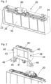
- Figure 1
- is a perspective view of a grille shutter assembly according to an embodiment of the present invention comprising a primary grille frame and a secondary grille frame,
- Figure 2
- is a further perspective view of the grille shutter assembly according to
fig. 1 in which the secondary grille frame is removed, - Figure 3
- is a further perspective view of the grille shutter assembly according to
fig. 1 in which the secondary grille frame is illustrated above the primary grille frame, - Figure 4
- is an exploded view of the grille shutter assembly according to
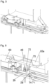
fig. 1 , - Figure 5
- is a detailed view of the connection between the primary grille frame and the secondary grille frame of the grille shutter assembly according to
fig. 1 , and - Figure 6
- is a detailed view of the connection between the primary coupling bar of the primary grille frame and the secondary coupling bar of the secondary grille frame of the grille shutter assembly according to
fig. 1 . - The figures show different views of different components and embodiments of the present invention. Identical or similar parts are labelled with identical reference numbers in all figures. For clarity reasons not all reference numbers are included in all figures.
-
Figures 1 to 6 illustrate an embodiment of agrille shutter assembly 10 comprising aprimary grille frame 20 with aprimary opening 25 and at least oneprimary lamella 30 extending across at least a portion of theprimary opening 25. Theprimary grille frame 20 comprises afirst side 21 and asecond side 22, thefirst side 21 and thesecond side 22 being two opposite sides of theprimary grille frame 20. Further, theprimary grille frame 20 comprises athird side 23 and afourth side 24, thethird side 23 and thefourth side 24 each connecting thefirst side 21 and thesecond side 22 and further being as well two opposite sides of theprimary grille frame 20. Especially, theprimary grille frame 20 can have a rectangular appearance. Theprimary grille frame 20 may be formed as a single piece. Alternatively, as shown in the figures, theprimary grille frame 20 may be an assembly of several parts. - The
primary lamella 30 is movably mounted relative to theprimary opening 25 of theprimary grille frame 20 between an open position, in which air is allowed to flow through theprimary opening 25, and a closed position, in which airflow through theprimary opening 25 is restricted (seefig. 1 ). To move between the open position and the closed position, theprimary lamella 30 can turn around a longitudinal axis L1. - The
primary lamella 30 comprises afirst end 31 and asecond end 32. Theprimary lamella 30 may be of rectangular shape to optimally cover the rectangularprimary opening 25. In an embodiment, thegrille shutter assembly 10, especially theprimary grille frame 20, may comprise a plurality ofprimary lamellas 30, theprimary lamellas 30 especially being arranged in a single row parallel to each other with their longitudinal axis L1 spaced apart. Allprimary lamellas 50 may have identical geometry. In a preferred embodiment, theprimary lamellas 30 are arranged such that theprimary opening 25 is covered to the largest possible extent when theprimary lamellas 30 are in their closed position. - The
primary lamella 30 can comprise a mountingpin 33 being arranged on thefirst end 31 and a further mountingpin 34 being arranged on thesecond end 32 of theprimary lamella 30 and extending in opposite directions to engage inholes first side 21 and thesecond side 22, of theprimary grille frame 20. - The plurality of
primary lamellas 30 may be coupled by aprimary coupling bar 26 for simultaneously moving theprimary lamellas 30. For coupling theprimary coupling bar 26 to theprimary lamellas 30, acoupling pin 35 may be attached to theprimary lamella 30, for example on aplate 35a attached sideways at thefirst end 31 of theprimary lamella 30. Thecoupling pin 35 can engage in ahole 27 of theprimary coupling bar 26. - An
actuator 60 may be attached to theprimary grille frame 20, theactuator 60 being connected to either theprimary coupling bar 26 or directly to one of the lamellas. In both cases it is possible to move all of theprimary lamellas 30 from the open position to the closed position or vice versa. In this embodiment, theactuator 60 is attached on thefirst side 21 of theprimary grille frame 20, especially on the outside of theprimary grille frame 20. - A
secondary grille frame 40 is attachable to theprimary grille frame 20, thesecondary grille frame 40 having an secondary 45 and at least onesecondary lamella 50 extending across at least a portion of thesecondary opening 45. Thesecondary grille frame 40 comprises afirst side 41 and asecond side 42, thefirst side 41 and thesecond side 42 being two opposite sides of thesecondary grille frame 40. Further, thesecondary grille frame 40 comprises athird side 43 and afourth side 44, thethird side 43 and thefourth side 44 each connecting thefirst side 41 and thesecond side 42 and further being as well two opposite sides of thesecondary grille frame 40. Especially, thesecondary grille frame 40 can have a rectangular appearance. - The
secondary lamella 50 is movably mounted relative to thesecondary opening 45 of thesecondary grille frame 40 between an open position, in which air is allowed to flow through thesecondary opening 45, and a closed position, in which airflow through thesecondary opening 45 is restricted (seefig. 1 ). To move between the open position and the closed position, thesecondary lamella 50 can turn around a longitudinal axis L2. - The
secondary lamella 50 comprises afirst end 51 and asecond end 52. Thesecondary lamella 50 may be of rectangular shape to optimally cover the rectangularsecondary opening 45. In an embodiment, thesecondary grille frame 40, may comprise a plurality ofsecondary lamellas 50, thesecondary lamellas 50 especially being arranged in a single row parallel to each other with their longitudinal axis L2 spaced apart. Allsecondary lamellas 50 may have identical geometry. In a preferred embodiment, thesecondary lamellas 50 are arranged such that thesecondary opening 45 is covered to the largest possible extent when thesecondary lamellas 50 are in their closed position. - The
secondary lamella 50 can comprise a mounting pin (not visible) being arranged on thefirst end 51 and a further mountingpin 54 being arranged on thesecond end 52 of thesecondary lamella 50 and extending in opposite directions to engage inholes first side 41 and thesecond side 42, of thesecondary grille frame 40. - The plurality of
secondary lamellas 50 may be coupled by asecondary coupling bar 46 for simultaneously moving thesecondary lamellas 50. For coupling thesecondary coupling bar 46 to thesecondary lamellas 50, acoupling pin 55 may be attached to thesecondary lamella 50, for example on aplate 55a attached sideways at thefirst end 51 of thesecondary lamella 50. Thecoupling pin 55 can engage in ahole 47 of thesecondary coupling bar 46. - Especially, the
secondary lamella 50 can have a geometry identical to the geometry of theprimary lamella 30. - The at least one
primary lamella 30 and the at least onesecondary lamella 50 are couplable by acoupling bar 70 for simultaneously moving the at least oneprimary lamella 30 and the at least onesecondary lamella 50 by means of the oneactuator 60. In case of a plurality ofprimary lamellas 30 and a plurality ofsecondary lamellas 50, thecoupling bar 70 may be connected to both theprimary coupling bar 26 and thesecondary coupling bar 46 or may couple directly both the plurality ofprimary lamellas 30 and the plurality ofsecondary lamellas 50 for simultaneously moving the plurality ofprimary lamellas 30 and the plurality ofsecondary lamellas 50 by means of the oneactuator 60. - For example, the
coupling bar 70 may be L-shaped. - In the embodiment illustrated in the figures, the
coupling bar 70 has afirst end 71 and a second end 72, thefirst end 71 being connected to theprimary coupling bar 26, in this example by means of apin 28 attached at theprimary coupling bar 26 which engages in ahole 74 attached at thefirst end 71 of thecoupling bar 70, and the second end 72 being connected to thesecondary coupling bar 46, in this example thecoupling bar 70 and thesecondary coupling bar 46 being formed in one piece (seefigure 6 ). - The
secondary grille frame 40 may be attachable to thefirst side 21 of theprimary grille frame 20. In other words, thesecondary grille frame 40 is disposed in direction of the longitudinal axis L1 of the at least oneprimary lamella 30. Especially, thesecondary grille frame 40 might be arranged above the primary grille frame 20 (seefigures 1 and3 ). - Preferably, the
first side 41 of thesecondary grille frame 40 is attachable to thefirst side 21 of theprimary grille frame 20. In this arrangement, the distance between theprimary coupling bar 26 and thesecondary coupling bar 46 might be smallest. - The
secondary grille frame 40 may be removably attachable to theprimary grille frame 20 byscrews 49 as shown in the figures or clips or alternatively may be attachable to theprimary grille frame 20 by soldering or welding. For attachment, in this embodiment thesecondary grille frame 40 comprises twodistance feet 48, preferably one of those attached at the corner between thefirst side 41 and thethird side 43 and the other one of those attached at the corner between thefirst side 41 and thefourth side 44 of thesecondary grille frame 40. Theactuator 60 may be placed between theprimary grille frame 20 and thesecondary grille frame 40, especially between thefirst side 21 of theprimary grille frame 20 and thefirst side 41 of thesecondary grille frame 40, most preferred between the twodistance feet 48. -
- 10
- grille frame assembly
- 20
- primary grille frame
- 21
- first side
- 22
- second side
- 23
- third side
- 24
- fourth side
- 25
- primary opening
- 26
- primary coupling bar
- 27
- hole
- 28
- pin
- 30
- primary lamella
- 31
- first end
- 32
- second end
- 33
- mounting pin
- 34
- mounting pin
- 35
- coupling pin
- 35a
- plate
- 40
- secondary grille frame
- 41
- first side
- 42
- second side
- 43
- third side
- 44
- fourth side
- 45
- secondary opening
- 46
- secondary coupling bar
- 47
- hole
- 48
- distance foot
- 49
- screw
- 50
- primary lamella
- 51
- first end
- 52
- second end
- 54
- mounting pin
- 55
- coupling pin
- 55a
- plate
- 60
- actuator
- 70
- coupling bar
- 71
- first end
- 72
- second end
- 74
- hole
- L1
- longitudinal axis
- L2
- longitudinal axis
Claims (12)
- Grille shutter assembly (10) comprising a primary grille frame (20) with a primary opening (25) and at least one primary lamella (30) extending across at least a portion of the primary opening (25), the primary lamella (30) being movably mounted relative to the primary opening (25) of the primary grille frame (20) between an open position and a closed position, and further comprising an actuator (60) for moving the at least one primary lamella (30),
characterized in that a secondary grille frame (40) is attachable to the primary grille frame (20), the secondary grille frame (40) comprising a secondary opening (45) and at least one secondary lamella (50) extending across at least a portion of the secondary opening (45), the secondary lamella (50) being movably mounted relative to the secondary opening (45) of the secondary grille frame (40) between an open position and a closed position, wherein the at least one primary lamella (30) and the at least one secondary lamella (50) are couplable by a coupling bar (70) for simultaneously moving the at least one primary lamella (30) and the at least one secondary lamella (50) by means of the one actuator (60). - Grille shutter assembly according to claim 1,
characterized in that the secondary grille frame (40) is removably attachable to the primary grille frame (20) by screws (49) or clips or is attachable to the primary grille (frame 20) by soldering or welding. - Grille shutter assembly according to claim 1 or 2,
characterized in that the primary grille frame (20) comprises a plurality of primary lamellas (30) arranged in a single row. - Grille shutter assembly according to claim 3,
characterized in that the plurality of primary lamellas (30) is coupled by a primary coupling bar (26) for simultaneously moving the primary lamellas (30) . - Grille shutter assembly according to one of the preceding claims,
characterized in that the secondary grille frame (40) comprises a plurality of secondary lamellas (50) arranged in a single row. - Grille shutter assembly according to claim 5,
characterized in that the plurality of secondary lamellas (50) is coupled by a secondary coupling bar (46) for simultaneously moving the secondary lamellas (50). - Grille shutter assembly according to one of the preceding claims,
characterized in that the coupling bar (70) is L-shaped. - Grille shutter assembly according to one of the preceding claims,
characterized in that the coupling bar (70) has a first end (71) and a second end (72), the first end (71) being connected to the primary coupling bar (26) and the second end (72) being connected to the secondary coupling bar (46). - Grille shutter assembly according to claims 3 and 5,
characterized in that the coupling bar (70) couples both the plurality of primary lamellas (30) and the plurality of secondary lamellas (50) for simultaneously moving the primary lamellas (30) and secondary lamellas (50). - Grille shutter assembly according to one of the preceding claims,
characterized in that the at least one primary lamella (30) comprises a first end (31) and a second end (32) and a longitudinal axis (L1), the primary grille frame (20) comprises a first side (21) and a second side (22), the first side (21) and the second side (22) being two opposite sides of the primary grille frame (20), wherein the first end (31) of the primary lamella (30) is attached to the first side (21) and the second end (32) of the primary lamella (30) is attached to the second side (22), and wherein the secondary grille frame (40) is attachable to the first side (21) of the primary grille frame (20). - Grille shutter assembly according to claim 9,
characterized in that the at least one secondary lamella (50) comprises a first end (51) and a second end (52) and a longitudinal axis (L2), the secondary grille frame (40) comprises a first side (41) and a second side (42), the first side (41) and the second side (42) being two opposite sides of the secondary grille frame (40), wherein the first end (51) of the secondary lamella (50) is attached to the first side (41) and the second end (52) of the secondary lamella (50) is attached to the second side (42), wherein the plurality of primary lamellas (30) is coupled by the primary coupling bar (26) close to the first end (31) of the primary lamellas (30), the plurality of secondary lamellas (50) is coupled by the secondary coupling bar (46) close to the first end (51) of the secondary lamellas (50), and wherein the first side (41) of the secondary grille frame (40) is attachable to the first side (21) of the primary grille frame (20). - Grille shutter assembly according to one of the preceding claims,
characterized in that the actuator (60) is arranged between the primary grille frame (20) and the secondary grille frame (40), especially between the first side (21) of the primary grille frame (20) and the first side (41) of the secondary grille frame (40).
Priority Applications (1)
| Application Number | Priority Date | Filing Date | Title |
|---|---|---|---|
| EP23197390.0A EP4523937A1 (en) | 2023-09-14 | 2023-09-14 | Grille shutter assembly |
Applications Claiming Priority (1)
| Application Number | Priority Date | Filing Date | Title |
|---|---|---|---|
| EP23197390.0A EP4523937A1 (en) | 2023-09-14 | 2023-09-14 | Grille shutter assembly |
Publications (1)
| Publication Number | Publication Date |
|---|---|
| EP4523937A1 true EP4523937A1 (en) | 2025-03-19 |
Family
ID=88069011
Family Applications (1)
| Application Number | Title | Priority Date | Filing Date |
|---|---|---|---|
| EP23197390.0A Pending EP4523937A1 (en) | 2023-09-14 | 2023-09-14 | Grille shutter assembly |
Country Status (1)
| Country | Link |
|---|---|
| EP (1) | EP4523937A1 (en) |
Citations (6)
| Publication number | Priority date | Publication date | Assignee | Title |
|---|---|---|---|---|
| WO2014150143A1 (en) | 2013-03-15 | 2014-09-25 | Srg Global, Inc. | Grille shutter assembly |
| GB2554397A (en) * | 2016-09-26 | 2018-04-04 | Jaguar Land Rover Ltd | System for engine cooling |
| WO2020214332A1 (en) * | 2019-03-22 | 2020-10-22 | Magna Exteriors Inc. | In mold assembly for active grille shutter system |
| CN216580101U (en) | 2021-12-09 | 2022-05-24 | 广州汽车集团股份有限公司 | Initiative air-inlet grille and car |
| FR3117950A1 (en) * | 2020-12-18 | 2022-06-24 | Valeo Systemes Thermiques | Device for shutting off airflow from the front face of a motor vehicle comprising several support frames |
| EP4054873A2 (en) * | 2019-12-27 | 2022-09-14 | Magna Exteriors Inc. | Modular aero device actuator and a modular active grille shutter system having a reduced number of vanes |
-
2023
- 2023-09-14 EP EP23197390.0A patent/EP4523937A1/en active Pending
Patent Citations (6)
| Publication number | Priority date | Publication date | Assignee | Title |
|---|---|---|---|---|
| WO2014150143A1 (en) | 2013-03-15 | 2014-09-25 | Srg Global, Inc. | Grille shutter assembly |
| GB2554397A (en) * | 2016-09-26 | 2018-04-04 | Jaguar Land Rover Ltd | System for engine cooling |
| WO2020214332A1 (en) * | 2019-03-22 | 2020-10-22 | Magna Exteriors Inc. | In mold assembly for active grille shutter system |
| EP4054873A2 (en) * | 2019-12-27 | 2022-09-14 | Magna Exteriors Inc. | Modular aero device actuator and a modular active grille shutter system having a reduced number of vanes |
| FR3117950A1 (en) * | 2020-12-18 | 2022-06-24 | Valeo Systemes Thermiques | Device for shutting off airflow from the front face of a motor vehicle comprising several support frames |
| CN216580101U (en) | 2021-12-09 | 2022-05-24 | 广州汽车集团股份有限公司 | Initiative air-inlet grille and car |
Similar Documents
| Publication | Publication Date | Title |
|---|---|---|
| DE10203054B4 (en) | Front grille design | |
| EP2296946B1 (en) | Sensor arrangement | |
| DE112020000214B4 (en) | mount for a vehicle-mounted camera | |
| EP0608422A1 (en) | Operator cabin of bulldozer | |
| US7080677B2 (en) | Motor-vehicle cargo-net assembly | |
| DE10247344A1 (en) | Room luminaire mounting structure | |
| KR20220116035A (en) | Modular aero device actuator and modular active grill shutter system with reduced vane count | |
| DE102007004649A1 (en) | Solenoid valve | |
| US5219191A (en) | Externally actuated enclosure latch assembly | |
| EP3363326A1 (en) | Drawer panel adjusting device | |
| US7163240B2 (en) | Vehicle door handle device | |
| EP1637371A2 (en) | Air outlet, in particular for a vehicle | |
| EP4509341B1 (en) | Grille shutter assembly | |
| EP1929840B1 (en) | Maintaining arrangement for a hob of a cooking appliance | |
| EP1377129B1 (en) | Door hinge mounting device for microwave oven | |
| EP0077928A2 (en) | Supporting device for control elements of a cooking range | |
| WO2019242944A1 (en) | Inverter housing | |
| US20110075430A1 (en) | Lamp arrangement | |
| WO2005090868A1 (en) | Control panel for an electric appliance | |
| KR20030067256A (en) | Top cover fix structure of air conditioner | |
| DE69922349T2 (en) | IMPROVED ULTRA-COMPACT AIR WASTE FOR BATHROOM | |
| DE3917637A1 (en) | MULTIPLE BUTTON SWITCH | |
| KR100558727B1 (en) | Assembly device | |
| DE102024209021A1 (en) | Built-in household appliance with specific positioning device for positioning in a built-in niche | |
| DE102008020128A1 (en) | Air conditioning unit and kit for an air conditioning unit |
Legal Events
| Date | Code | Title | Description |
|---|---|---|---|
| PUAI | Public reference made under article 153(3) epc to a published international application that has entered the european phase |
Free format text: ORIGINAL CODE: 0009012 |
|
| STAA | Information on the status of an ep patent application or granted ep patent |
Free format text: STATUS: THE APPLICATION HAS BEEN PUBLISHED |
|
| AK | Designated contracting states |
Kind code of ref document: A1 Designated state(s): AL AT BE BG CH CY CZ DE DK EE ES FI FR GB GR HR HU IE IS IT LI LT LU LV MC ME MK MT NL NO PL PT RO RS SE SI SK SM TR |
|
| STAA | Information on the status of an ep patent application or granted ep patent |
Free format text: STATUS: REQUEST FOR EXAMINATION WAS MADE |
|
| 17P | Request for examination filed |
Effective date: 20250827 |
|
| P01 | Opt-out of the competence of the unified patent court (upc) registered |
Free format text: CASE NUMBER: UPC_APP_0003357_4523937/2026 Effective date: 20260130 |
|
| RAP3 | Party data changed (applicant data changed or rights of an application transferred) |
Owner name: MOTHERSON INNOVATIONS COMPANY LIMITED |