EP4523935A1 - Vehicle door glass assembly, vehicle door assembly and vehicle - Google Patents
Vehicle door glass assembly, vehicle door assembly and vehicle Download PDFInfo
- Publication number
- EP4523935A1 EP4523935A1 EP23830377.0A EP23830377A EP4523935A1 EP 4523935 A1 EP4523935 A1 EP 4523935A1 EP 23830377 A EP23830377 A EP 23830377A EP 4523935 A1 EP4523935 A1 EP 4523935A1
- Authority
- EP
- European Patent Office
- Prior art keywords
- vehicle door
- door glass
- along
- vehicle
- counterweight
- Prior art date
- Legal status (The legal status is an assumption and is not a legal conclusion. Google has not performed a legal analysis and makes no representation as to the accuracy of the status listed.)
- Pending
Links
Images


Classifications
-
- B—PERFORMING OPERATIONS; TRANSPORTING
- B60—VEHICLES IN GENERAL
- B60J—WINDOWS, WINDSCREENS, NON-FIXED ROOFS, DOORS, OR SIMILAR DEVICES FOR VEHICLES; REMOVABLE EXTERNAL PROTECTIVE COVERINGS SPECIALLY ADAPTED FOR VEHICLES
- B60J1/00—Windows; Windscreens; Accessories therefor
- B60J1/08—Windows; Windscreens; Accessories therefor arranged at vehicle sides
- B60J1/12—Windows; Windscreens; Accessories therefor arranged at vehicle sides adjustable
- B60J1/16—Windows; Windscreens; Accessories therefor arranged at vehicle sides adjustable slidable
- B60J1/17—Windows; Windscreens; Accessories therefor arranged at vehicle sides adjustable slidable vertically
-
- B—PERFORMING OPERATIONS; TRANSPORTING
- B60—VEHICLES IN GENERAL
- B60J—WINDOWS, WINDSCREENS, NON-FIXED ROOFS, DOORS, OR SIMILAR DEVICES FOR VEHICLES; REMOVABLE EXTERNAL PROTECTIVE COVERINGS SPECIALLY ADAPTED FOR VEHICLES
- B60J10/00—Sealing arrangements
- B60J10/70—Sealing arrangements specially adapted for windows or windscreens
- B60J10/74—Sealing arrangements specially adapted for windows or windscreens for sliding window panes, e.g. sash guides
- B60J10/76—Sealing arrangements specially adapted for windows or windscreens for sliding window panes, e.g. sash guides for window sashes; for glass run channels
-
- B—PERFORMING OPERATIONS; TRANSPORTING
- B60—VEHICLES IN GENERAL
- B60J—WINDOWS, WINDSCREENS, NON-FIXED ROOFS, DOORS, OR SIMILAR DEVICES FOR VEHICLES; REMOVABLE EXTERNAL PROTECTIVE COVERINGS SPECIALLY ADAPTED FOR VEHICLES
- B60J5/00—Doors
- B60J5/04—Doors arranged at the vehicle sides
- B60J5/0401—Upper door structure
- B60J5/0402—Upper door structure window frame details, including sash guides and glass runs
-
- B—PERFORMING OPERATIONS; TRANSPORTING
- B60—VEHICLES IN GENERAL
- B60J—WINDOWS, WINDSCREENS, NON-FIXED ROOFS, DOORS, OR SIMILAR DEVICES FOR VEHICLES; REMOVABLE EXTERNAL PROTECTIVE COVERINGS SPECIALLY ADAPTED FOR VEHICLES
- B60J5/00—Doors
- B60J5/04—Doors arranged at the vehicle sides
- B60J5/0412—Lower door structure
- B60J5/0416—Assembly panels to be installed in doors as a module with components, e.g. lock or window lifter, attached thereto
-
- B—PERFORMING OPERATIONS; TRANSPORTING
- B60—VEHICLES IN GENERAL
- B60J—WINDOWS, WINDSCREENS, NON-FIXED ROOFS, DOORS, OR SIMILAR DEVICES FOR VEHICLES; REMOVABLE EXTERNAL PROTECTIVE COVERINGS SPECIALLY ADAPTED FOR VEHICLES
- B60J10/00—Sealing arrangements
- B60J10/70—Sealing arrangements specially adapted for windows or windscreens
- B60J10/74—Sealing arrangements specially adapted for windows or windscreens for sliding window panes, e.g. sash guides
- B60J10/79—Sealing arrangements specially adapted for windows or windscreens for sliding window panes, e.g. sash guides for flush-glass windows, i.e. for windows flush with the vehicle body or the window frame
Definitions
- the present disclosure relates to the technical field of vehicles, and particularly to a vehicle door glass assembly, a vehicle door assembly and a vehicle.
- a flush vehicle door glass assembly widely used at present is equipped with guide brackets bonded at front and rear ends of the vehicle door glass.
- the guide bracket is clamped and assembled with a sealing strip on a vehicle door sheet-metal guide rail, and an outer surface of the vehicle door glass is flush with the sealing strip, i.e., an inner surface of the vehicle door glass, the guide bracket and an edge of the vehicle door glass are overlapped with the sealing strip, and the outer surface of the vehicle door glass is not overlapped with the sealing strip.
- the glass can be better stabilized and the glass can be prevented from vibration under an action of airflow.
- the present disclosure aims to provide a vehicle door glass assembly, a vehicle door assembly and a vehicle, so as to solve the existing problems of jamming caused by the lifting and sliding of the vehicle door glass, and leakages of air and water caused by the fact that the glass is easy to deviate along a horizontal direction and a sealing strip at one end is worn.
- the present disclosure provides a vehicle door glass assembly, including: a vehicle door glass with a first end and a second end which are opposite to each other along a length direction of the vehicle door glass, the first end and the second end of the vehicle door glass being configured for sealed sliding fit with a vehicle door body along a lifting direction, the vehicle door glass being driven by a lifting mechanism to move along the lifting direction, and a force-bearing point between the lifting mechanism and the vehicle door glass being a main support point; and a counterweight structure mounted on the vehicle door glass; in which in a state where the vehicle door glass moves along the lifting direction, the center of gravity of the vehicle door glass is adjusted by the counterweight structure, and moments of force generated by forces acting on the vehicle door glass relative to the main support point are balanced with each other.
- the present disclosure further provides a vehicle door assembly, including the aforementioned vehicle door glass assembly, the vehicle door assembly further including: the vehicle door main body; and the lifting mechanism mounted on the vehicle door body.
- the present disclosure further provides a vehicle, including the aforementioned vehicle door assembly.
- a counterweight structure is disposed on a vehicle door glass, and in a state where the vehicle door glass moves along a lifting direction, the center of gravity of the vehicle door glass is adjusted by the counterweight structure, so that moments of force generated by forces acting on the vehicle door glass relative to a main support point between a lifting mechanism and the vehicle door glass can be balanced with each other, the stability of an end of the vehicle door glass with poor stability can be improved, and the end of the vehicle door glass with poor stability can be prevented from being tilted towards an end with good stability, thereby ensuring that the lifting mechanism is capable of driving the vehicle door glass to slide smoothly along the lifting direction without the occurrence of jamming; at the same time, avoiding a sealing failure between the vehicle door glass and a vehicle door body caused by the occurrence of a gap between the end of the vehicle door glass with poor stability and the vehicle door body.
- 1 vehicle door glass; 11: first end; 12: second end; 13: first holder; 14: second holder; 15: bracket hole; 16: inner surface; 17: outer surface; 2: counterweight structure; 21: counterweight block; 22: mounting fixture; 221: first clamping groove; 222: first adhesive layer; 223: second adhesive layer; 224: second clamping groove; 3: first sealing strip; 31: first assembling groove; 32: first lip; 33: second lip; 4: second sealing strip; 41: second assembling groove; 42: third lip; 43: fourth lip; 5: first limiting structure; 51: first guide bracket; 52: first guide groove; 53: first limiting surface; 6: second limiting structure; 61: second guide bracket; 62: second guide groove; 63: second limiting surface; 7: third limiting structure; 71: third guide bracket; 72: third guide groove; 73: third limiting surface; 8: weatherstrip ; 9: lifting mechanism; 91: bracket.
- the present disclosure provides a vehicle door glass assembly, which includes a vehicle door body; a vehicle door glass 1 with a first end 11 and a second end 12 which are opposite to each other along a length direction X thereof, the first end 11 and the second end 12 of the vehicle door glass 1 being configured for sealed sliding fit with the vehicle door body along a lifting direction Z, the vehicle door glass 1 being driven by a lifting mechanism 9 to move along the lifting direction Z, and a force-bearing point between the lifting mechanism 9 and the vehicle door glass 1 being a main support point O; and a counterweight structure 2 mounted on the vehicle door glass 1; in which in a state where the vehicle door glass 1 moves along the lifting direction Z, the center of gravity O 1 of the vehicle door glass 1 is adjusted by the counterweight structure 2, and moments of force generated by forces acting on the vehicle door glass 1 relative to the main support point O are balanced with each other.
- a counterweight structure 2 is disposed on a vehicle door glass 1, and in a state where the vehicle door glass 1 moves along a lifting direction Z, the center of gravity of the vehicle door glass 1 is adjusted by means of the counterweight structure 2, so that moments of force generated by forces acting on the vehicle door glass 1 relative to a main support point O between a lifting mechanism 9 and the vehicle door glass 1 can be balanced with each other, the stability of an end of the vehicle door glass 1 with poor stability can be improved, and the end of the vehicle door glass 1 with poor stability can be prevented from being tilted towards an end with good stability, thereby ensuring that the lifting mechanism 9 is capable of driving the vehicle door glass 1 to slide smoothly along the lifting direction Z without the occurrence of jamming; at the same time, avoiding a sealing failure between the vehicle door glass 1 and a vehicle door body caused by the occurrence of a gap between the end of the vehicle door glass 1 with poor stability and the vehicle door body.
- the vehicle door glass 1 may be the vehicle door glass 1 on a front vehicle door or on a rear vehicle door. Due to the streamlined design of the vehicle body, the vehicle door glass 1 has an asymmetric structure with respect to its center of gravity, resulting in a great difference in stability between the first end 11 and the second end 12 of the vehicle door glass 1. Therefore, by disposing the counterweight structure 2, the stability of the end of the vehicle door glass 1 with poor stability can be improved.
- the lifting mechanism 9 is connected to the vehicle door glass 1 through a bracket 91.
- the vehicle door glass 1 is provided with a bracket hole 15 for mounting the bracket 91. A center of the bracket hole 15 is the position of the main support point O.
- the counterweight structure 2 is not in contact with the lifting mechanism 9, that is, the counterweight structure 2 does not supply power for the lowering of the vehicle door glass 1.
- the specific structure and the working principle of the lifting mechanism 9 are the same as those in the prior art, which will not be described in detail here.
- the vehicle door glass 1 is of a flush type, that is, an outer surface 17 of the vehicle door glass 1 facing the exterior of the vehicle is substantially flush with an outer surface of the vehicle door body, and only an inner surface 16 of the vehicle door glass 1 facing the interior of the vehicle and an edge of the vehicle door glass 1 are in sealed sliding fit with the vehicle door body.
- the vehicle door glass 1 is of a non-flush type, that is, the inner and outer surfaces of the vehicle door glass are respectively overlapped and in sealed sliding fit with the sealing strip on the vehicle door body.
- the vehicle door glass 1 of this embodiment is capable of improving the aerodynamic and aesthetic characteristics of the vehicle, but the stability during lifting and sliding and the stability of the seal are insufficient.
- the counterweight structure 2 both the stability of the flush type vehicle door glass 1 during lifting and sliding and the stability of the seal are improved.
- a length of the first end 11 of the vehicle door glass 1 extending along the lifting direction Z is less than a length of the second end 12 of the vehicle door glass 1 extending along the lifting direction Z, and the center of gravity of the counterweight structure 2 is located between the main support point O and the first end 11 of the vehicle door glass 1.
- a sealed sliding mating surface between the second end 12 of the vehicle door glass 1 and the vehicle door body is larger than the sealed sliding mating surface between the first end 11 of the vehicle door glass 1 and the vehicle door body, so that the stability of the second end 12 of the vehicle door glass 1 is greater than the stability of the first end 11 of the vehicle door glass 1.
- the counterweight structure 2 is disposed close to the first end 11 of the vehicle door glass 1 relative to the second end 12 of the vehicle door glass 1, thereby improving the stability of the first end 11 of the vehicle door glass 1.
- the vehicle door glass 1 is the vehicle door glass 1 on a front vehicle door
- the first end 11 of the vehicle door glass 1 is a front end of the vehicle door glass 1 close to a vehicle head
- the second end 12 of the vehicle door glass 1 is a rear end of the vehicle door glass 1 close to a rear of the vehicle.
- a weatherstrip 8 is mounted on the vehicle door body, the vehicle door glass 1 passes through the weatherstrip 8 along the lifting direction Z to be in sealed sliding fit with the weatherstrip 8, and the counterweight structure 2 is located below the weatherstrip 8.
- the counterweight structure 2 is always in an invisible position on the vehicle door, and will not affect the lifting and sliding range of the vehicle door glass 1. Specifically, in a state where the vehicle door glass 1 is completely closed, a distance between the counterweight structure 2 and the weatherstrip 8 is not less than 10 mm, so as to ensure that there will be no interference between the counterweight structure 2 and the weatherstrip 8.
- the moment of force described in the present disclosure is a vector product of a distance vector from the main support point O to a force action point and the force, a direction from the main support point O to the first end of the vehicle door glass is defined as a positive direction, and a direction from the main support point O to the second end of the vehicle door glass is defined as a negative direction.
- the center O 2 of the weatherstrip 8 and the center of gravity O 1 of the vehicle door glass 1 are both located between the main support point O and the first end 11 of the vehicle door glass 1, so M 1 , M 3 , M vehicle door glass and M counterweight are all positive, and M 2 is negative.
- M 1 , M 3 , M vehicle door glass and M counterweight are all positive, and M 2 is negative.
- the center O 2 of the weatherstrip 8 and the center of gravity O 1 of the vehicle door glass 1 are both located between the main support point O and the first end 11 of the vehicle door glass 1, so M 1 , M 3 , M vehicle door glass and M counterweight are all positive, and M 2 is negative.
- the center O 2 of the weatherstrip 8 and the center of gravity O 1 of the vehicle door glass 1 are both located between the main support point O and the first end 11 of the vehicle door glass 1, so M 1 , M 3 , M vehicle door glass and M counterweight are all positive, and M 2 is negative.
- the center of gravity of the vehicle door glass is located on a side of the main support point close to the second end of the vehicle door glass or on the movement path of the main support point, and M vehicle door glass is zero.
- the center O 2 of the weatherstrip is located between the main support point O and the second end of the vehicle door glass, and M 3 is negative.
- a length direction of the vehicle door glass 1 is X
- a thickness direction of the vehicle door glass 1 is Y. Since the vehicle door glass 1 is thin, the distance from the force acting on the vehicle door glass 1 to the main support point O along the direction Y is almost zero, and the generated moment of force is small, which will not affect the stability of the lifting and sliding of the vehicle door glass 1 and the stability of the seal and then is ignored, that is, the vehicle door glass 1 does not deviate along the direction Y. Thus, it is only necessary to consider the moment of force generated by the force acting on the vehicle door glass 1 relative to the main support point O along the direction X.
- M 1 F 1 ⁇ L 1 ⁇ cos ⁇
- M 2 F 2 ⁇ L 2 ⁇ cos ⁇
- M 3 F 3 ⁇ L 3 ⁇ cos ⁇ cos ⁇
- M vehicle door glass m vehicle door glass g ⁇ L vehicle door glass ⁇ cos ⁇
- M counterweight +m counterweight g ⁇ L counterweight cos ⁇
- ⁇ represents an angle of an included angle between a mid-perpendicular of the weatherstrip 8 and the vertical direction
- ⁇ represents an angle of an included angle between the lifting direction and the vertical direction
- L 1 represents a distance vector from the main support point O to the first end 11 of the vehicle door glass 1 along the direction X
- F 1 represents a sliding friction force between the first end 11 of the vehicle door glass 1 and the vehicle door body
- L 2 represents a distance vector from the main support point O to the second end 12 of the vehicle door glass 1 along the direction X
- F 2 represents a sliding friction force between the second end 12 of the vehicle door glass 1 and the vehicle door body
- L 3 represents
- m counterweight is 0.1 kg to 2 kg, optionally 0.3 kg to 1.1 kg. If the counterweight structure 2 is too heavy, an excessive impulse may be easily caused to the vehicle door glass 1 when the vehicle door is opened or closed, and if the counterweight structure 2 is too light, it is impossible to improve the stability of the first end 11 of the vehicle door glass 1.
- ⁇ is 0°.
- a first sealing strip 3 and a second sealing strip 4 are mounted on the vehicle door body along the lifting direction Z, in which the first end 11 of the vehicle door glass 1 is in sealed sliding fit with the vehicle door body through the first sealing strip 3, and the second end 12 of the vehicle door glass 1 is in sealed sliding fit with the vehicle door body through the second sealing strip 4.
- FIGS. 1 and FIGS. 2 are mounted on the vehicle door body along the lifting direction Z, in which the first end 11 of the vehicle door glass 1 is in sealed sliding fit with the vehicle door body through the first sealing strip 3, and the second end 12 of the vehicle door glass 1 is in sealed sliding fit with the vehicle door body through the second sealing strip 4.
- the outer surface 17 of the vehicle door glass 1 is flush with the first sealing strip 3 and the second sealing strip 4, only the inner surface 16 and the edge of the first end 11 of the vehicle door glass 1 are in sealed sliding fit with the first sealing strip 3, and only the inner surface 16 and the edge of the second end 12 of the vehicle door glass 1 are in sealed sliding fit with the second sealing strip 4.
- At least one first limiting structure 5 is disposed between the first end 11 of the vehicle door glass 1 and the first sealing strip 3.
- at least one second limiting structure 6 and at least one third limiting structure 7 are disposed between the second end 12 of the vehicle door glass 1 and the second sealing strip 4.
- the first limiting structure 5 and the second limiting structure 6 are cooperated to limit the movement of the vehicle door glass 1 along a thickness direction Y of the vehicle door glass, and the third limiting structure 7 limits the movement of the vehicle door glass 1 along the length direction X of the vehicle door glass.
- the first limiting structure 5 includes a first guide bracket 51, which is mounted on the first end 11 of the vehicle door glass 1 along the lifting direction Z; a first guide groove 52 is formed in the first sealing strip 3 along the lifting direction, and provided therein with two first limiting surfaces 53 opposite to each other along the thickness direction Y of the vehicle door glass 1; and the first guide bracket 51 is abutted against the two first limiting surfaces 53 and is slidable in the first guide groove 52.
- reference numeral 51 in FIG. 3 refers to the cross-sections of the same first guide bracket 51.
- the first sealing strip 3 is further provided with a first assembling groove 31 along the lifting direction Z, and the first assembling groove 31 is communicated with the first guide groove 52 and cooperated with the first end 11 of the vehicle door glass 1.
- At least one first lip 32 and at least one second lip 33 are disposed in the first assembling groove 31, in which the first lip 32 is in sealed sliding fit with the inner surface 16 of the first end 11 of the vehicle door glass 1, and the second lip 33 is in sealed sliding fit with the edge of the first end 11 of the vehicle door glass 1.
- the second limiting structure 6 includes a second guide bracket 61
- the third limiting structure 7 includes a third guide bracket 71
- the second guide bracket 61 and the third guide bracket 71 are mounted on the second end 12 of the vehicle door glass 1 at an interval along the lifting direction Z
- the second sealing strip 4 is provided with a second guide groove 62 along the lifting direction.
- the second guide groove 62 is provided therein with two second limiting surfaces 63 and two third limiting surfaces 73, the two second limiting surfaces 63 are oppositely disposed along the thickness direction Y of the vehicle door glass 1, and the two third limiting surfaces 73 are oppositely disposed along the length direction X of the vehicle door glass 1.
- the second guide bracket 61 is abutted against the two second limiting surfaces 63 and is slidable in the second guide groove 62
- the third guide bracket 71 is abutted against the two third limiting surfaces 73 and is slidable in the second guide groove 62.
- reference numeral 61 in FIG. 4 refers to the cross-sections of the same second guide bracket 61
- reference numeral 71 in FIG. 5 refers to the cross-sections of the same third guide bracket 71.
- three second guide brackets 61 and two third guide brackets 71 are mounted on the inner surface 16 of the second end 12 of the vehicle door glass 1 through the second holder 14.
- the two third guide brackets 71 are disposed close to a top end and a bottom end of the vehicle door glass 1, and the three second guide brackets 61 are arranged between the two third guide brackets 71 at intervals.
- the second sealing strip 4 is further provided with a second assembling groove 41 along the lifting direction Z, and the second assembling groove 41 is communicated with the second guide groove 62 and the third guide groove 72, and the second assembling groove 41 is cooperated with the second end 12 of the vehicle door glass 1.
- the second assembling groove 41 is provided therein with at least one third lip 42 and at least one fourth lip 43, wherein the third lip 42 is in sealed sliding fit with the inner surface 16 of the second end 12 of the vehicle door glass 1, and the fourth lip 43 is in sealed sliding fit with the edge of the second end 12 of the vehicle door glass 1.
- first guide brackets 51 and the first holder 13 are integrated.
- Three second guide brackets 61, two third guide brackets 71 and the second holder 14 are integrated.
- one of the first guide brackets 51 is directly fixed on the inner surface 16 of the first end 11 of the vehicle door glass 1.
- One of the second guide brackets 61 and one of the third guide brackets 71 are directly fixed to the inner surface 16 of the second end 12 of the vehicle door glass 1.
- a sliding friction force between the first end 11 of the vehicle door glass 1 and the first sealing strip 3 is f 1
- a sliding friction force between the first guide bracket 51 and the first sealing strip 3 is F 1Y
- a sliding friction force between the second guide bracket 61 and the second sealing strip 4 is F 2Y
- a sliding friction force between the third guide bracket 71 and the second sealing strip 4 is F 2X
- a sliding friction force between the second end 12 of the vehicle door glass 1 and the second sealing strip 4 is f 2
- F 1 F 1 Y + f 1
- F 2 F 2 X + F 2 Y + f 2 .
- the magnitudes of F 2Y and F 1Y are similar, and the magnitudes of f 2 and f 1 are similar. Due to the existence of F 2X , the stability of the second end 12 of the vehicle door glass 1 during lifting and sliding is stronger than that of the first end 11 of the vehicle door glass 1 during lifting and sliding. Therefore, by adding the counterweight structure 2 on a side of the main support point O close to the first end 11 of the vehicle door glass 1, it is beneficial to improving the stability and balance of the first end 11 of the vehicle door glass 1 and reducing the tilting risk of the first end 11 of the vehicle door glass 1.
- an abrasion amount of the second sealing strip 4 is generally greater than the abrasion amount of the first sealing strip 3.
- the counterweight structure 2 between the first guide bracket 51 and the main support point O, it is beneficial to increasing the moment of force of the vehicle door glass 1 on a side of the main support point O close to the first guide bracket 51, and reducing the risk of gaps forming between the first guide bracket 51 and the first sealing strip 3, and between the vehicle door glass 1 and the first sealing strip 3 caused by the deviation of the vehicle door glass 1 towards the second sealing strip 4.
- the counterweight structure 2 includes at least one counterweight block 21, the vehicle door glass 1 includes the inner surface 16 facing the interior of a vehicle and the outer surface 17 facing the exterior of the vehicle, and the counterweight block 21 is mounted on the inner surface 16, the outer surface 17 and/or an edge of the vehicle door glass 1.
- the counterweight block 21 is mounted on the vehicle door glass 1 through a mounting fixture 22, which is adhesive fixed on the inner surface 16, the outer surface 17 and/or the edge of the vehicle door glass 1, and the counterweight block 21 is clamped on the mounting fixture 22 and adhesive fixed. In a process of adhesive fixation, it is unnecessary to cooperate with other tooling to clamp and fix the counterweight block 21.
- the mounting fixture 22 is provided with at least one clamping groove.
- the mounting fixture 22 is provided with a first clamping groove 221 and a second clamping groove 224, and the counterweight block 21 is clamped in the first clamping groove 221 and adhesive fixed with the mounting fixture 22 by a first adhesive layer 222.
- the edge of the vehicle door glass 1 extends into the second clamping groove 224 and is adhesive fixed by a second adhesive layer 223.
- the mounting fixture 22 is only provided with the first clamping groove 221, and the counterweight block 21 is clamped in the first clamping groove 221 and adhesive fixed by the first adhesive layer 222.
- the mounting fixture 22 is adhesive fixed on the inner surface 16 or the outer surface 17 of the vehicle door glass 1 by the second adhesive layer 223.
- two counterweight blocks 21 with the same weight are symmetrically clamped in the first clamping grooves 221 of two mounting fixtures 22, and are adhesive fixed by the first adhesive layer 222.
- the two mounting fixtures 22 are symmetrically adhesive fixed on the inner surface 16 and the outer surface 17 of the vehicle door glass 1 by two second adhesive layers 223.
- the counterweight block is adhesive directly fixed on the vehicle door glass by an adhesive tape, or directly adhesive fixed on the vehicle door glass by polyurethane glue.
- the present disclosure further provides a vehicle door assembly, which includes a vehicle door glass assembly, and further includes: a vehicle door body; and a lifting mechanism 9 mounted on the vehicle door body.
- vehicle door glass assembly, the vehicle door body and the lifting mechanism 9 in this embodiment are the same as those in Embodiment 1 in terms of the specific structure, the working principle and the advantageous effects, which will not be described in detail here.
- the present disclosure further provides a vehicle, which includes a vehicle door assembly.
- vehicle door assembly in this embodiment is the same as that in Embodiment 2 in terms of the specific structure, the working principle and the advantageous effects, which will not be described in detail here.
Landscapes
- Engineering & Computer Science (AREA)
- Mechanical Engineering (AREA)
- Window Of Vehicle (AREA)
Abstract
Description
- The present disclosure claims priority to
Chinese Patent Application No. 202210762585.5, an invention title of "vehicle door glass assembly, vehicle door assembly and vehicle" and filed on June 30, 2022 - The present disclosure relates to the technical field of vehicles, and particularly to a vehicle door glass assembly, a vehicle door assembly and a vehicle.
- A flush vehicle door glass assembly widely used at present is equipped with guide brackets bonded at front and rear ends of the vehicle door glass. The guide bracket is clamped and assembled with a sealing strip on a vehicle door sheet-metal guide rail, and an outer surface of the vehicle door glass is flush with the sealing strip, i.e., an inner surface of the vehicle door glass, the guide bracket and an edge of the vehicle door glass are overlapped with the sealing strip, and the outer surface of the vehicle door glass is not overlapped with the sealing strip. Through the fit between the guide bracket and the sealing strip, a better guiding effect is achieved in the vertical lifting and sliding of the vehicle door glass. Meanwhile, during the travelling of the vehicle, due to the clamping between the guide bracket and the sealing strip, the glass can be better stabilized and the glass can be prevented from vibration under an action of airflow. However, there are problems of jamming caused by the lifting and sliding of the glass, and leakages of air and water caused by the fact that the glass is easy to deviate along its extension direction and the sealing strip at one end is worn.
- The present disclosure aims to provide a vehicle door glass assembly, a vehicle door assembly and a vehicle, so as to solve the existing problems of jamming caused by the lifting and sliding of the vehicle door glass, and leakages of air and water caused by the fact that the glass is easy to deviate along a horizontal direction and a sealing strip at one end is worn.
- The above objective of the present disclosure can be achieved by the following technical solutions.
- The present disclosure provides a vehicle door glass assembly, including: a vehicle door glass with a first end and a second end which are opposite to each other along a length direction of the vehicle door glass, the first end and the second end of the vehicle door glass being configured for sealed sliding fit with a vehicle door body along a lifting direction, the vehicle door glass being driven by a lifting mechanism to move along the lifting direction, and a force-bearing point between the lifting mechanism and the vehicle door glass being a main support point; and a counterweight structure mounted on the vehicle door glass; in which in a state where the vehicle door glass moves along the lifting direction, the center of gravity of the vehicle door glass is adjusted by the counterweight structure, and moments of force generated by forces acting on the vehicle door glass relative to the main support point are balanced with each other.
- The present disclosure further provides a vehicle door assembly, including the aforementioned vehicle door glass assembly, the vehicle door assembly further including: the vehicle door main body; and the lifting mechanism mounted on the vehicle door body.
- The present disclosure further provides a vehicle, including the aforementioned vehicle door assembly.
- The present disclosure has the following characteristics and advantages:
- In the vehicle door glass assembly, the vehicle door assembly and the vehicle according to the present disclosure, a counterweight structure is disposed on a vehicle door glass, and in a state where the vehicle door glass moves along a lifting direction, the center of gravity of the vehicle door glass is adjusted by the counterweight structure, so that moments of force generated by forces acting on the vehicle door glass relative to a main support point between a lifting mechanism and the vehicle door glass can be balanced with each other, the stability of an end of the vehicle door glass with poor stability can be improved, and the end of the vehicle door glass with poor stability can be prevented from being tilted towards an end with good stability, thereby ensuring that the lifting mechanism is capable of driving the vehicle door glass to slide smoothly along the lifting direction without the occurrence of jamming; at the same time, avoiding a sealing failure between the vehicle door glass and a vehicle door body caused by the occurrence of a gap between the end of the vehicle door glass with poor stability and the vehicle door body.
- In order to explain the technical solutions in the embodiment of the present disclosure more clearly, the drawings required in the description of the embodiments will be briefly introduced below. It will be understood that the drawings involved in the following description only illustrate some embodiments of the present disclosure, and those of ordinary skill in the art can obtain other drawings from these drawings without paying any creative effort.
-
FIG. 1 illustrates a structural diagram of a vehicle door assembly according to the present disclosure. -
FIG. 2 illustrates a structural diagram of a vehicle door glass according to a first embodiment. -
FIG. 3 illustrates a structural diagram of a first limiting structure according to a first embodiment. -
FIG. 4 illustrates a structural diagram of a second limiting structure according to a first embodiment. -
FIG. 5 illustrates a structural diagram of a third limiting structure according to a first embodiment. -
FIG. 6 illustrates a cross-sectional view of a counterweight structure according to a first embodiment. -
FIG. 7 illustrates a structural diagram of a vehicle door glass according to a second embodiment. -
FIG. 8 illustrates a cross-sectional view of a counterweight structure according to a second embodiment. -
FIG. 9 illustrates a structural diagram of a vehicle door glass according to a third embodiment. -
FIG. 10 illustrates a cross-sectional view of a counterweight structure according to a third embodiment. - In the drawings: 1: vehicle door glass; 11: first end; 12: second end; 13: first holder; 14: second holder; 15: bracket hole; 16: inner surface; 17: outer surface; 2: counterweight structure; 21: counterweight block; 22: mounting fixture; 221: first clamping groove; 222: first adhesive layer; 223: second adhesive layer; 224: second clamping groove; 3: first sealing strip; 31: first assembling groove; 32: first lip; 33: second lip; 4: second sealing strip; 41: second assembling groove; 42: third lip; 43: fourth lip; 5: first limiting structure; 51: first guide bracket; 52: first guide groove; 53: first limiting surface; 6: second limiting structure; 61: second guide bracket; 62: second guide groove; 63: second limiting surface; 7: third limiting structure; 71: third guide bracket; 72: third guide groove; 73: third limiting surface; 8: weatherstrip ; 9: lifting mechanism; 91: bracket.
- The technical solutions in the embodiments of the present disclosure will be clearly and completely described below with reference to the drawings for the embodiments of the present disclosure. Obviously, those described are only a part, rather than all, of the embodiments of the present disclosure. Based on the embodiments in the present disclosure, any other embodiment obtained by those of ordinary skill in the art without paying any creative effort should fall within the protection scope of the present disclosure.
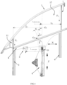
- As illustrated in
FIG. 1 , the present disclosure provides a vehicle door glass assembly, which includes a vehicle door body; avehicle door glass 1 with afirst end 11 and asecond end 12 which are opposite to each other along a length direction X thereof, thefirst end 11 and thesecond end 12 of thevehicle door glass 1 being configured for sealed sliding fit with the vehicle door body along a lifting direction Z, thevehicle door glass 1 being driven by a lifting mechanism 9 to move along the lifting direction Z, and a force-bearing point between the lifting mechanism 9 and thevehicle door glass 1 being a main support point O; and acounterweight structure 2 mounted on thevehicle door glass 1; in which in a state where thevehicle door glass 1 moves along the lifting direction Z, the center of gravity O1 of thevehicle door glass 1 is adjusted by thecounterweight structure 2, and moments of force generated by forces acting on thevehicle door glass 1 relative to the main support point O are balanced with each other. - In the vehicle door glass assembly according to the present disclosure, a
counterweight structure 2 is disposed on avehicle door glass 1, and in a state where thevehicle door glass 1 moves along a lifting direction Z, the center of gravity of thevehicle door glass 1 is adjusted by means of thecounterweight structure 2, so that moments of force generated by forces acting on thevehicle door glass 1 relative to a main support point O between a lifting mechanism 9 and thevehicle door glass 1 can be balanced with each other, the stability of an end of thevehicle door glass 1 with poor stability can be improved, and the end of thevehicle door glass 1 with poor stability can be prevented from being tilted towards an end with good stability, thereby ensuring that the lifting mechanism 9 is capable of driving thevehicle door glass 1 to slide smoothly along the lifting direction Z without the occurrence of jamming; at the same time, avoiding a sealing failure between thevehicle door glass 1 and a vehicle door body caused by the occurrence of a gap between the end of thevehicle door glass 1 with poor stability and the vehicle door body. - Specifically, the
vehicle door glass 1 may be thevehicle door glass 1 on a front vehicle door or on a rear vehicle door. Due to the streamlined design of the vehicle body, thevehicle door glass 1 has an asymmetric structure with respect to its center of gravity, resulting in a great difference in stability between thefirst end 11 and thesecond end 12 of thevehicle door glass 1. Therefore, by disposing thecounterweight structure 2, the stability of the end of thevehicle door glass 1 with poor stability can be improved. Referring toFIG. 2 , the lifting mechanism 9 is connected to thevehicle door glass 1 through abracket 91. Thevehicle door glass 1 is provided with abracket hole 15 for mounting thebracket 91. A center of thebracket hole 15 is the position of the main support point O. Thecounterweight structure 2 is not in contact with the lifting mechanism 9, that is, thecounterweight structure 2 does not supply power for the lowering of thevehicle door glass 1. The specific structure and the working principle of the lifting mechanism 9 are the same as those in the prior art, which will not be described in detail here. - As illustrated in
FIGS. 1 to 5 , in this embodiment, thevehicle door glass 1 is of a flush type, that is, anouter surface 17 of thevehicle door glass 1 facing the exterior of the vehicle is substantially flush with an outer surface of the vehicle door body, and only aninner surface 16 of thevehicle door glass 1 facing the interior of the vehicle and an edge of thevehicle door glass 1 are in sealed sliding fit with the vehicle door body. Optionally, thevehicle door glass 1 is of a non-flush type, that is, the inner and outer surfaces of the vehicle door glass are respectively overlapped and in sealed sliding fit with the sealing strip on the vehicle door body. Compared with the non-flush type vehicle door glass, thevehicle door glass 1 of this embodiment is capable of improving the aerodynamic and aesthetic characteristics of the vehicle, but the stability during lifting and sliding and the stability of the seal are insufficient. Thus, by disposing thecounterweight structure 2, both the stability of the flush typevehicle door glass 1 during lifting and sliding and the stability of the seal are improved. - In the embodiment of the present disclosure, a length of the
first end 11 of thevehicle door glass 1 extending along the lifting direction Z is less than a length of thesecond end 12 of thevehicle door glass 1 extending along the lifting direction Z, and the center of gravity of thecounterweight structure 2 is located between the main support point O and thefirst end 11 of thevehicle door glass 1. A sealed sliding mating surface between thesecond end 12 of thevehicle door glass 1 and the vehicle door body is larger than the sealed sliding mating surface between thefirst end 11 of thevehicle door glass 1 and the vehicle door body, so that the stability of thesecond end 12 of thevehicle door glass 1 is greater than the stability of thefirst end 11 of thevehicle door glass 1. Thecounterweight structure 2 is disposed close to thefirst end 11 of thevehicle door glass 1 relative to thesecond end 12 of thevehicle door glass 1, thereby improving the stability of thefirst end 11 of thevehicle door glass 1. Specifically, thevehicle door glass 1 is thevehicle door glass 1 on a front vehicle door, thefirst end 11 of thevehicle door glass 1 is a front end of thevehicle door glass 1 close to a vehicle head, and thesecond end 12 of thevehicle door glass 1 is a rear end of thevehicle door glass 1 close to a rear of the vehicle. - As illustrated in
FIG. 1 , aweatherstrip 8 is mounted on the vehicle door body, thevehicle door glass 1 passes through theweatherstrip 8 along the lifting direction Z to be in sealed sliding fit with theweatherstrip 8, and thecounterweight structure 2 is located below theweatherstrip 8. Thecounterweight structure 2 is always in an invisible position on the vehicle door, and will not affect the lifting and sliding range of thevehicle door glass 1. Specifically, in a state where thevehicle door glass 1 is completely closed, a distance between thecounterweight structure 2 and theweatherstrip 8 is not less than 10 mm, so as to ensure that there will be no interference between thecounterweight structure 2 and theweatherstrip 8. - In the embodiment of the present disclosure, the relationship between the moments of force generated by the forces acting on the
vehicle door glass 1 relative to the main support point O can be expressed as follows:

where M1 represents a moment of force generated by a sliding friction force between thefirst end 11 of thevehicle door glass 1 and the vehicle door body relative to the main support point O, M2 represents a moment of force generated by a sliding friction force between thesecond end 12 of thevehicle door glass 1 and the vehicle door body relative to the main support point O, M3 represents a moment of force generated by a sliding friction force between theweatherstrip 8 and the vehicle door body relative to the main support point O, Mvehicle door glass represents a moment of force generated by the gravity of thevehicle door glass 1 relative to the main support point O, and Mcounterweight represents a moment generated by the gravity of thecounterweight structure 2 relative to the main support point O. - The moment of force described in the present disclosure is a vector product of a distance vector from the main support point O to a force action point and the force, a direction from the main support point O to the first end of the vehicle door glass is defined as a positive direction, and a direction from the main support point O to the second end of the vehicle door glass is defined as a negative direction.
- In this embodiment, the center O2 of the
weatherstrip 8 and the center of gravity O1 of thevehicle door glass 1 are both located between the main support point O and thefirst end 11 of thevehicle door glass 1, so M1, M3, Mvehicle door glass and Mcounterweight are all positive, and M2 is negative. By disposing the center O2 of theweatherstrip 8 and the center of gravity O1 of thevehicle door glass 1 on a side of the main support point O close to thefirst end 11 of thevehicle door glass 1, it is beneficial to further improving the stability of thefirst end 11 of thevehicle door glass 1. Optionally, the center of the weatherstrip is located on a side of the main support point close to the second end of thevehicle door glass 1 or in a movement path of the main support point. Optionally, the center of gravity of the vehicle door glass is located on a side of the main support point close to the second end of the vehicle door glass or on the movement path of the main support point, and Mvehicle door glass is zero. Optionally, the center O2 of the weatherstrip is located between the main support point O and the second end of the vehicle door glass, and M3 is negative. - As illustrated in
FIGS. 1 ,3 and 4 , a length direction of thevehicle door glass 1 is X, and a thickness direction of thevehicle door glass 1 is Y. Since thevehicle door glass 1 is thin, the distance from the force acting on thevehicle door glass 1 to the main support point O along the direction Y is almost zero, and the generated moment of force is small, which will not affect the stability of the lifting and sliding of thevehicle door glass 1 and the stability of the seal and then is ignored, that is, thevehicle door glass 1 does not deviate along the direction Y. Thus, it is only necessary to consider the moment of force generated by the force acting on thevehicle door glass 1 relative to the main support point O along the direction X. - Specifically, M1=F1·L1·cosβ; M2=F2·L2·cosβ; M3=F3·L3·cosα·cosβ; Mvehicle door glass=mvehicle door glassg·Lvehicle door glass·cosβ; Mcounterweight=+mcounterweightg·Lcounterweight cosβ; where α represents an angle of an included angle between a mid-perpendicular of the weatherstrip 8 and the vertical direction, β represents an angle of an included angle between the lifting direction and the vertical direction, L1 represents a distance vector from the main support point O to the first end 11 of the vehicle door glass 1 along the direction X, F1 represents a sliding friction force between the first end 11 of the vehicle door glass 1 and the vehicle door body, L2 represents a distance vector from the main support point O to the second end 12 of the vehicle door glass 1 along the direction X, F2 represents a sliding friction force between the second end 12 of the vehicle door glass 1 and the vehicle door body, L3 represents a distance vector from the main support point O to a midpoint O2 of the weatherstrip 8 along the direction X , F3 represents a sliding friction force between the weatherstrip 8 and the vehicle door glass 1, Lvehicle door glass represents a distance vector from the main support point O to the center of gravity O1 of the vehicle door glass 1 along the direction X , Mvehicle door glass 1 represents a weight of the vehicle door glass 1, Lcounterweight represents a distance vector from the main support point O to the center of gravity of the counterweight structure 2 along the direction X , and mcounterweight represents a weight of the counterweight structure 2.
- In this embodiment, mcounterweight is 0.1 kg to 2 kg, optionally 0.3 kg to 1.1 kg. If the
counterweight structure 2 is too heavy, an excessive impulse may be easily caused to thevehicle door glass 1 when the vehicle door is opened or closed, and if thecounterweight structure 2 is too light, it is impossible to improve the stability of thefirst end 11 of thevehicle door glass 1. β is 0°. Thus the relationship between the moments of force generated by the force acting on thevehicle door glass 1 relative to the main support point along the direction X can be expressed as follows:F1·L1+F3·L3·cosα+ mvehicle door glass 1g · Lvehicle door glass +mcounterweightg·Lcounterweight+ F2·L2=0;
that is, Lcounterweight= (-F2·L2-F1·L1-F3·L3·cosα-mvehicle door glass 1g·Lvehicle door glass)/ (mcounterweightg), so as to determine the mounting position of thecounterweight structure 2. - As illustrated in
FIG. 1 , in the embodiment of the present disclosure, afirst sealing strip 3 and asecond sealing strip 4 are mounted on the vehicle door body along the lifting direction Z, in which thefirst end 11 of thevehicle door glass 1 is in sealed sliding fit with the vehicle door body through thefirst sealing strip 3, and thesecond end 12 of thevehicle door glass 1 is in sealed sliding fit with the vehicle door body through thesecond sealing strip 4. Specifically, as illustrated inFIGS. 3 to 5 , theouter surface 17 of thevehicle door glass 1 is flush with thefirst sealing strip 3 and thesecond sealing strip 4, only theinner surface 16 and the edge of thefirst end 11 of thevehicle door glass 1 are in sealed sliding fit with thefirst sealing strip 3, and only theinner surface 16 and the edge of thesecond end 12 of thevehicle door glass 1 are in sealed sliding fit with thesecond sealing strip 4. - As illustrated in
FIG. 3 , at least one first limitingstructure 5 is disposed between thefirst end 11 of thevehicle door glass 1 and thefirst sealing strip 3. As illustrated inFIGS. 4 and5 , at least one second limitingstructure 6 and at least one third limitingstructure 7 are disposed between thesecond end 12 of thevehicle door glass 1 and thesecond sealing strip 4. The first limitingstructure 5 and the second limitingstructure 6 are cooperated to limit the movement of thevehicle door glass 1 along a thickness direction Y of the vehicle door glass, and the third limitingstructure 7 limits the movement of thevehicle door glass 1 along the length direction X of the vehicle door glass. Because of a long extension length of thesecond end 12 of thevehicle door glass 1 along the lifting direction Z, and a short extension length of thefirst end 11 of thevehicle door glass 1 along the lifting direction Z, it is possible to ensure that thevehicle door glass 1 can be reliably limited in both the direction X and the direction Y by simultaneously disposing the second limitingstructure 6 and the third limitingstructure 7 between thesecond end 12 of thevehicle door glass 1 and thesecond sealing strip 4, and only disposing the first limitingstructure 5 between thefirst end 11 of thevehicle door glass 1 and thefirst sealing strip 3. - As illustrated in
FIG. 3 , in the embodiment of the present disclosure, the first limitingstructure 5 includes afirst guide bracket 51, which is mounted on thefirst end 11 of thevehicle door glass 1 along the lifting direction Z; afirst guide groove 52 is formed in thefirst sealing strip 3 along the lifting direction, and provided therein with two first limitingsurfaces 53 opposite to each other along the thickness direction Y of thevehicle door glass 1; and thefirst guide bracket 51 is abutted against the two first limitingsurfaces 53 and is slidable in thefirst guide groove 52. Specifically,reference numeral 51 inFIG. 3 refers to the cross-sections of the samefirst guide bracket 51. Referring toFIG. 2 , the twofirst guide brackets 51 are mounted on theinner surface 16 of thefirst end 11 of thevehicle door glass 1 through thefirst holder 13. Thefirst sealing strip 3 is further provided with afirst assembling groove 31 along the lifting direction Z, and the first assemblinggroove 31 is communicated with thefirst guide groove 52 and cooperated with thefirst end 11 of thevehicle door glass 1. At least onefirst lip 32 and at least onesecond lip 33 are disposed in the first assemblinggroove 31, in which thefirst lip 32 is in sealed sliding fit with theinner surface 16 of thefirst end 11 of thevehicle door glass 1, and thesecond lip 33 is in sealed sliding fit with the edge of thefirst end 11 of thevehicle door glass 1. - As illustrated in
FIGS. 4 and5 , the second limitingstructure 6 includes asecond guide bracket 61, and the third limitingstructure 7 includes athird guide bracket 71, thesecond guide bracket 61 and thethird guide bracket 71 are mounted on thesecond end 12 of thevehicle door glass 1 at an interval along the lifting direction Z, and thesecond sealing strip 4 is provided with asecond guide groove 62 along the lifting direction. Thesecond guide groove 62 is provided therein with two second limitingsurfaces 63 and two third limitingsurfaces 73, the two second limitingsurfaces 63 are oppositely disposed along the thickness direction Y of thevehicle door glass 1, and the two third limitingsurfaces 73 are oppositely disposed along the length direction X of thevehicle door glass 1. Thesecond guide bracket 61 is abutted against the two second limitingsurfaces 63 and is slidable in thesecond guide groove 62, and thethird guide bracket 71 is abutted against the two third limitingsurfaces 73 and is slidable in thesecond guide groove 62. - Specifically,
reference numeral 61 inFIG. 4 refers to the cross-sections of the samesecond guide bracket 61, andreference numeral 71 inFIG. 5 refers to the cross-sections of the samethird guide bracket 71. Referring toFIG. 2 , threesecond guide brackets 61 and twothird guide brackets 71 are mounted on theinner surface 16 of thesecond end 12 of thevehicle door glass 1 through thesecond holder 14. The twothird guide brackets 71 are disposed close to a top end and a bottom end of thevehicle door glass 1, and the threesecond guide brackets 61 are arranged between the twothird guide brackets 71 at intervals. Thesecond sealing strip 4 is further provided with asecond assembling groove 41 along the lifting direction Z, and thesecond assembling groove 41 is communicated with thesecond guide groove 62 and thethird guide groove 72, and thesecond assembling groove 41 is cooperated with thesecond end 12 of thevehicle door glass 1. Thesecond assembling groove 41 is provided therein with at least onethird lip 42 and at least onefourth lip 43, wherein thethird lip 42 is in sealed sliding fit with theinner surface 16 of thesecond end 12 of thevehicle door glass 1, and thefourth lip 43 is in sealed sliding fit with the edge of thesecond end 12 of thevehicle door glass 1. - As illustrated in
FIGS. 2 and7 , in this embodiment and a second embodiment, twofirst guide brackets 51 and thefirst holder 13 are integrated. Threesecond guide brackets 61, twothird guide brackets 71 and thesecond holder 14 are integrated. As illustrated inFIG. 9 , in a third embodiment, one of thefirst guide brackets 51 is directly fixed on theinner surface 16 of thefirst end 11 of thevehicle door glass 1. One of thesecond guide brackets 61 and one of thethird guide brackets 71 are directly fixed to theinner surface 16 of thesecond end 12 of thevehicle door glass 1. - As illustrated in
FIGS. 3, 4 and5 , a sliding friction force between thefirst end 11 of thevehicle door glass 1 and thefirst sealing strip 3 is f1, a sliding friction force between thefirst guide bracket 51 and thefirst sealing strip 3 is F1Y, a sliding friction force between thesecond guide bracket 61 and thesecond sealing strip 4 is F2Y, a sliding friction force between thethird guide bracket 71 and thesecond sealing strip 4 is F2X, a sliding friction force between thesecond end 12 of thevehicle door glass 1 and thesecond sealing strip 4 is f2, and there are the following relationships:

- Since the
vehicle door glass 1 has no deviation along the direction Y, the magnitudes of F2Y and F1Y are similar, and the magnitudes of f2 and f1 are similar. Due to the existence of F2X, the stability of thesecond end 12 of thevehicle door glass 1 during lifting and sliding is stronger than that of thefirst end 11 of thevehicle door glass 1 during lifting and sliding. Therefore, by adding thecounterweight structure 2 on a side of the main support point O close to thefirst end 11 of thevehicle door glass 1, it is beneficial to improving the stability and balance of thefirst end 11 of thevehicle door glass 1 and reducing the tilting risk of thefirst end 11 of thevehicle door glass 1. - After the
first sealing strip 3 and thesecond sealing strip 4 are abraded after long-term sliding, since the total length of thesecond guide bracket 61 and thethird guide bracket 71 is long, an abrasion amount of thesecond sealing strip 4 is generally greater than the abrasion amount of thefirst sealing strip 3. However, because of the friction forces between thesecond guide bracket 61 and thesecond sealing strip 4, and between thethird guide bracket 71 and thesecond sealing strip 4 are both existed along the direction X and the direction Y, even if thesecond sealing strip 4 is abraded, the friction forces between thesecond guide bracket 61 and thesecond sealing strip 4, and the friction forces between thethird guide bracket 71 and thesecond sealing strip 4, are still greater than the friction force between thefirst guide bracket 51 and thefirst sealing strip 3, so that thevehicle door glass 1 is still prone to tilt towards thesecond sealing strip 4, resulting in gaps between thefirst guide bracket 51 and thefirst sealing strip 3, and between thevehicle door glass 1 and thefirst sealing strip 3. According to the present disclosure, by adding thecounterweight structure 2 between thefirst guide bracket 51 and the main support point O, it is beneficial to increasing the moment of force of thevehicle door glass 1 on a side of the main support point O close to thefirst guide bracket 51, and reducing the risk of gaps forming between thefirst guide bracket 51 and thefirst sealing strip 3, and between thevehicle door glass 1 and thefirst sealing strip 3 caused by the deviation of thevehicle door glass 1 towards thesecond sealing strip 4. - As illustrated in
FIGS. 6 to 10 , in the embodiment of the present disclosure, thecounterweight structure 2 includes at least onecounterweight block 21, thevehicle door glass 1 includes theinner surface 16 facing the interior of a vehicle and theouter surface 17 facing the exterior of the vehicle, and thecounterweight block 21 is mounted on theinner surface 16, theouter surface 17 and/or an edge of thevehicle door glass 1. - As illustrated in
FIGS. 6 ,8 and10 , thecounterweight block 21 is mounted on thevehicle door glass 1 through a mountingfixture 22, which is adhesive fixed on theinner surface 16, theouter surface 17 and/or the edge of thevehicle door glass 1, and thecounterweight block 21 is clamped on the mountingfixture 22 and adhesive fixed. In a process of adhesive fixation, it is unnecessary to cooperate with other tooling to clamp and fix thecounterweight block 21. Specifically, the mountingfixture 22 is provided with at least one clamping groove. - As illustrated in
FIG. 6 , in this embodiment, the mountingfixture 22 is provided with afirst clamping groove 221 and asecond clamping groove 224, and thecounterweight block 21 is clamped in thefirst clamping groove 221 and adhesive fixed with the mountingfixture 22 by a firstadhesive layer 222. The edge of thevehicle door glass 1 extends into thesecond clamping groove 224 and is adhesive fixed by a secondadhesive layer 223. - As illustrated in
FIG. 8 , in a second embodiment, the mountingfixture 22 is only provided with thefirst clamping groove 221, and thecounterweight block 21 is clamped in thefirst clamping groove 221 and adhesive fixed by the firstadhesive layer 222. The mountingfixture 22 is adhesive fixed on theinner surface 16 or theouter surface 17 of thevehicle door glass 1 by the secondadhesive layer 223. - As illustrated in
FIG. 10 , in a third embodiment, two counterweight blocks 21 with the same weight are symmetrically clamped in thefirst clamping grooves 221 of two mountingfixtures 22, and are adhesive fixed by the firstadhesive layer 222. The two mountingfixtures 22 are symmetrically adhesive fixed on theinner surface 16 and theouter surface 17 of thevehicle door glass 1 by two second adhesive layers 223. - Optionally, the counterweight block is adhesive directly fixed on the vehicle door glass by an adhesive tape, or directly adhesive fixed on the vehicle door glass by polyurethane glue.
- Referring to
FIG. 1 , the present disclosure further provides a vehicle door assembly, which includes a vehicle door glass assembly, and further includes: a vehicle door body; and a lifting mechanism 9 mounted on the vehicle door body. The vehicle door glass assembly, the vehicle door body and the lifting mechanism 9 in this embodiment are the same as those inEmbodiment 1 in terms of the specific structure, the working principle and the advantageous effects, which will not be described in detail here. - The present disclosure further provides a vehicle, which includes a vehicle door assembly. The vehicle door assembly in this embodiment is the same as that in
Embodiment 2 in terms of the specific structure, the working principle and the advantageous effects, which will not be described in detail here. - Those described above are only several embodiments of the present disclosure, and those skilled in the art can make various modifications or variations to the embodiments of the present disclosure according to the disclosure of the application document without departing from the spirit and scope of the present disclosure.
Claims (12)
- A vehicle door glass assembly, comprising:a vehicle door glass with a first end and a second end, which are opposite to each other along a length direction of the vehicle door glass, the first end and the second end of the vehicle door glass being configured for sealed sliding fit with a vehicle door body along a lifting direction, the vehicle door glass being driven by a lifting mechanism to move along the lifting direction, and a force-bearing point between the lifting mechanism and the vehicle door glass being a main support point; anda counterweight structure mounted on the vehicle door glass;wherein in a state where the vehicle door glass moves along the lifting direction, the center of gravity of the vehicle door glass is adjusted by the counterweight structure, and moments of force generated by forces acting on the vehicle door glass relative to the main support point are balanced with each other.
- The vehicle door glass assembly according to claim 1, wherein,
a length of the first end of the vehicle door glass extending along the lifting direction is less than a length of the second end of the vehicle door glass extending along the lifting direction, and the center of gravity of the counterweight structure is located between the main support point and the first end of the vehicle door glass. - The vehicle door glass assembly according to claim 2, wherein,
a weatherstrip is mounted on the vehicle door body, the vehicle door glass passes through the weatherstrip along the lifting direction to be in sealed sliding fit with the weatherstrip , and the counterweight structure is located below the weatherstrip . - The vehicle door glass assembly according to claim 3, wherein,the moments of force generated by the forces acting on the vehicle door glass relative to the main support point have a relationship:
 where M1 represents a moment of force generated by a sliding friction force between the first end of the vehicle door glass and the vehicle door body relative to the main support point, M2 represents a moment of force generated by a sliding friction force between the second end of the vehicle door glass and the vehicle door body relative to the main support point, M3 represents a moment of force generated by a sliding friction force between the weatherstrip and the vehicle door body relative to the main support point, Mvehicle door glass represents a moment of force generated by the gravity of the vehicle door glass relative to the main support point, and Mcounterweight represents a moment of force generated by the gravity of the counterweight structure relative to the main support point.
 - The vehicle door glass assembly according to claim 1, wherein,
a first sealing strip and a second sealing strip are mounted on the vehicle door body along the lifting direction, the first end of the vehicle door glass is in sealed sliding fit with the vehicle door body through the first sealing strip, and the second end of the vehicle door glass is in sealed sliding fit with the vehicle door body through the second sealing strip. - The vehicle door glass assembly according to claim 5, wherein,
at least one first limiting structure is disposed between the first end of the vehicle door glass and the first sealing strip, at least one second limiting structure and at least one third limiting structure are disposed between the second end of the vehicle door glass and the second sealing strip, the first limiting structure and the second limiting structure are cooperated to limit the movement of the vehicle door glass along a thickness direction of the vehicle door glass, and the third limiting structure limits the movement of the vehicle door glass along the length direction of the vehicle door glass. - The vehicle door glass assembly according to claim 6, wherein,
the first limiting structure comprises a first guide bracket, which is mounted on the first end of the vehicle door glass along the lifting direction; a first guide groove is formed in the first sealing strip along the lifting direction, and two first limiting surfaces opposite to each other along the thickness direction of the vehicle door glass are provided in the first guide groove; and the first guide bracket abuts against the two first limiting surfaces and is slidable in the first guide groove. - The vehicle door glass assembly according to claim 6, wherein,
the second limiting structure comprises a second guide bracket, and the third limiting structure comprises a third guide bracket; the second guide bracket and the third guide bracket are mounted on the second end of the vehicle door glass at an interval along the lifting direction, and the second sealing strip is provided with a second guide groove along the lifting direction; the second guide groove is provided therein with two second limiting surfaces and two third limiting surfaces; the two second limiting surfaces are oppositely disposed along the thickness direction of the vehicle door glass, and the two third limiting surfaces are oppositely disposed along the length direction of the vehicle door glass; the second guide bracket abuts against the two second limiting surfaces and is slidable in the second guide groove, and the third guide bracket abuts against the two third limiting surfaces and is slidable in the second guide groove. - The vehicle door glass assembly according to any one of claims 1 to 8, wherein,
the counterweight structure comprises at least one counterweight block, the vehicle door glass comprises an inner surface facing the interior of a vehicle and an outer surface facing the exterior of the vehicle, and the counterweight block is mounted on the inner surface, the outer surface and/or an edge of the vehicle door glass. - The vehicle door glass assembly according to claim 9, wherein,
the counterweight block is mounted on the vehicle door glass through a mounting fixture, which is adhesively fixed on the inner surface, the outer surface and/or the edge of the vehicle door glass, and the counterweight block is clamped on the mounting fixture and adhesively fixed. - A vehicle door assembly, comprising the vehicle door glass assembly according to any one of claims 1 to 10, the vehicle door assembly further comprising:the vehicle door main body; andthe lifting mechanism mounted on the vehicle door body.
- A vehicle, comprising the vehicle door assembly according to claim 11.
Applications Claiming Priority (2)
| Application Number | Priority Date | Filing Date | Title |
|---|---|---|---|
| CN202210762585.5A CN115027237B (en) | 2022-06-30 | 2022-06-30 | Door glass assembly, door assembly and vehicle |
| PCT/CN2023/103585 WO2024002208A1 (en) | 2022-06-30 | 2023-06-29 | Vehicle door glass assembly, vehicle door assembly and vehicle |
Publications (2)
| Publication Number | Publication Date |
|---|---|
| EP4523935A1 true EP4523935A1 (en) | 2025-03-19 |
| EP4523935A4 EP4523935A4 (en) | 2025-08-27 |
Family
ID=83129631
Family Applications (1)
| Application Number | Title | Priority Date | Filing Date |
|---|---|---|---|
| EP23830377.0A Pending EP4523935A4 (en) | 2022-06-30 | 2023-06-29 | VEHICLE DOOR GLASS ASSEMBLY, VEHICLE DOOR ASSEMBLY AND VEHICLE |
Country Status (4)
| Country | Link |
|---|---|
| EP (1) | EP4523935A4 (en) |
| KR (1) | KR20250006997A (en) |
| CN (1) | CN115027237B (en) |
| WO (1) | WO2024002208A1 (en) |
Families Citing this family (2)
| Publication number | Priority date | Publication date | Assignee | Title |
|---|---|---|---|---|
| CN115027237B (en) * | 2022-06-30 | 2024-08-13 | 福耀玻璃工业集团股份有限公司 | Door glass assembly, door assembly and vehicle |
| CN116141930A (en) * | 2023-02-03 | 2023-05-23 | 福耀玻璃工业集团股份有限公司 | Glass assembly system with lifting function and automobile |
Family Cites Families (10)
| Publication number | Priority date | Publication date | Assignee | Title |
|---|---|---|---|---|
| FR2732274B1 (en) * | 1995-03-31 | 1997-05-30 | Peugeot | DEVICE FOR HOLDING A SLIDING WINDOW MOUNTED IN A MOTOR VEHICLE DOOR |
| CN2888030Y (en) * | 2005-08-21 | 2007-04-11 | 重庆长安汽车股份有限公司 | Lifting system for automobile door glass |
| EP2567842B1 (en) * | 2010-05-07 | 2017-06-21 | Toyota Jidosha Kabushiki Kaisha | Vehicle light control glass device |
| JP5501907B2 (en) * | 2010-09-13 | 2014-05-28 | 本田技研工業株式会社 | Glass seal holding structure |
| JP2016064717A (en) * | 2014-09-24 | 2016-04-28 | トヨタ車体株式会社 | Door structure with frame |
| CN104986020B (en) * | 2015-07-14 | 2017-04-12 | 安徽江淮汽车集团股份有限公司 | Automobile front door glass assembly and automobile front door assembly |
| CN110962552A (en) * | 2018-09-30 | 2020-04-07 | 长城汽车股份有限公司 | Automobile door glass mounting structure |
| CN112554701A (en) * | 2020-12-07 | 2021-03-26 | 安徽华菱汽车有限公司 | Design method, design device and design system of vehicle window lifter |
| CN114407628B (en) * | 2021-12-20 | 2024-04-02 | 上汽通用汽车有限公司 | Vehicle door assembly and vehicle |
| CN115027237B (en) * | 2022-06-30 | 2024-08-13 | 福耀玻璃工业集团股份有限公司 | Door glass assembly, door assembly and vehicle |
-
2022
- 2022-06-30 CN CN202210762585.5A patent/CN115027237B/en active Active
-
2023
- 2023-06-29 EP EP23830377.0A patent/EP4523935A4/en active Pending
- 2023-06-29 KR KR1020247040586A patent/KR20250006997A/en active Pending
- 2023-06-29 WO PCT/CN2023/103585 patent/WO2024002208A1/en not_active Ceased
Also Published As
| Publication number | Publication date |
|---|---|
| EP4523935A4 (en) | 2025-08-27 |
| JP2025520368A (en) | 2025-07-03 |
| WO2024002208A1 (en) | 2024-01-04 |
| KR20250006997A (en) | 2025-01-13 |
| CN115027237B (en) | 2024-08-13 |
| CN115027237A (en) | 2022-09-09 |
Similar Documents
| Publication | Publication Date | Title |
|---|---|---|
| EP4523935A1 (en) | Vehicle door glass assembly, vehicle door assembly and vehicle | |
| RU2608198C2 (en) | Vehicle smooth glazing assembly | |
| JPH0349049Y2 (en) | ||
| US7934342B2 (en) | Sliding window assembly | |
| RU2608785C2 (en) | Automotive glazing unit assembly method | |
| US4069617A (en) | Vehicle window guide assembly | |
| US11261633B2 (en) | Power slide window | |
| US4502247A (en) | Guide rail for a window regulator and slide guide mechanism employing the same | |
| US9388019B2 (en) | Elevator car | |
| US11208834B2 (en) | Power slide window | |
| US4688847A (en) | Vehicle window installation | |
| CA1220246A (en) | Window pane adjustable in height, particularly for motor vehicles | |
| CN208530243U (en) | Door glass installation structure and car door and car | |
| CN217022143U (en) | Window glass guide rail structure, door and car | |
| EP4286187B1 (en) | Sealing strip structure and sealing device | |
| CN221113471U (en) | Glass slider of door and door, vehicle | |
| CN215794074U (en) | Automobile wheel arch sealing strip and mounting structure thereof | |
| CN208530252U (en) | Installation structure of vehicle door glass and arrangements for automotive doors and automobile | |
| US11273691B2 (en) | Door structure of vehicle | |
| CN212354377U (en) | Helicopter cockpit door transparent member sliding window non-surface-difference structure | |
| CN217415425U (en) | Glass assemblies and window structures for vehicle window structures | |
| CN223735813U (en) | Frameless front triangular window | |
| CN120116704B (en) | Zero-step differential window glass guide rail structure, system, assembly method and its vehicle | |
| CN216128118U (en) | Sunroof guide rail easy to assemble | |
| JP2006177147A (en) | Guide rail for window regulator system |
Legal Events
| Date | Code | Title | Description |
|---|---|---|---|
| STAA | Information on the status of an ep patent application or granted ep patent |
Free format text: STATUS: THE INTERNATIONAL PUBLICATION HAS BEEN MADE |
|
| PUAI | Public reference made under article 153(3) epc to a published international application that has entered the european phase |
Free format text: ORIGINAL CODE: 0009012 |
|
| STAA | Information on the status of an ep patent application or granted ep patent |
Free format text: STATUS: REQUEST FOR EXAMINATION WAS MADE |
|
| 17P | Request for examination filed |
Effective date: 20241210 |
|
| AK | Designated contracting states |
Kind code of ref document: A1 Designated state(s): AL AT BE BG CH CY CZ DE DK EE ES FI FR GB GR HR HU IE IS IT LI LT LU LV MC ME MK MT NL NO PL PT RO RS SE SI SK SM TR |
|
| A4 | Supplementary search report drawn up and despatched |
Effective date: 20250728 |
|
| RIC1 | Information provided on ipc code assigned before grant |
Ipc: B60J 1/17 20060101AFI20250722BHEP Ipc: E05F 15/689 20150101ALI20250722BHEP Ipc: B60J 10/76 20160101ALI20250722BHEP |
|
| DAV | Request for validation of the european patent (deleted) | ||
| DAX | Request for extension of the european patent (deleted) |