EP4523932A1 - A thermal management module for a vehicle - Google Patents
A thermal management module for a vehicle Download PDFInfo
- Publication number
- EP4523932A1 EP4523932A1 EP23197039.3A EP23197039A EP4523932A1 EP 4523932 A1 EP4523932 A1 EP 4523932A1 EP 23197039 A EP23197039 A EP 23197039A EP 4523932 A1 EP4523932 A1 EP 4523932A1
- Authority
- EP
- European Patent Office
- Prior art keywords
- housing portion
- fluid
- management module
- thermal management
- mounting
- Prior art date
- Legal status (The legal status is an assumption and is not a legal conclusion. Google has not performed a legal analysis and makes no representation as to the accuracy of the status listed.)
- Withdrawn
Links
Images


Classifications
-
- B—PERFORMING OPERATIONS; TRANSPORTING
- B60—VEHICLES IN GENERAL
- B60H—ARRANGEMENTS OF HEATING, COOLING, VENTILATING OR OTHER AIR-TREATING DEVICES SPECIALLY ADAPTED FOR PASSENGER OR GOODS SPACES OF VEHICLES
- B60H1/00—Heating, cooling or ventilating devices
- B60H1/00485—Valves for air-conditioning devices, e.g. thermostatic valves
-
- B—PERFORMING OPERATIONS; TRANSPORTING
- B60—VEHICLES IN GENERAL
- B60K—ARRANGEMENT OR MOUNTING OF PROPULSION UNITS OR OF TRANSMISSIONS IN VEHICLES; ARRANGEMENT OR MOUNTING OF PLURAL DIVERSE PRIME-MOVERS IN VEHICLES; AUXILIARY DRIVES FOR VEHICLES; INSTRUMENTATION OR DASHBOARDS FOR VEHICLES; ARRANGEMENTS IN CONNECTION WITH COOLING, AIR INTAKE, GAS EXHAUST OR FUEL SUPPLY OF PROPULSION UNITS IN VEHICLES
- B60K11/00—Arrangement in connection with cooling of propulsion units
-
- F—MECHANICAL ENGINEERING; LIGHTING; HEATING; WEAPONS; BLASTING
- F01—MACHINES OR ENGINES IN GENERAL; ENGINE PLANTS IN GENERAL; STEAM ENGINES
- F01P—COOLING OF MACHINES OR ENGINES IN GENERAL; COOLING OF INTERNAL-COMBUSTION ENGINES
- F01P11/00—Component parts, details, or accessories not provided for in, or of interest apart from, groups F01P1/00 - F01P9/00
- F01P11/02—Liquid-coolant filling, overflow, venting, or draining devices
- F01P11/029—Expansion reservoirs
-
- F—MECHANICAL ENGINEERING; LIGHTING; HEATING; WEAPONS; BLASTING
- F01—MACHINES OR ENGINES IN GENERAL; ENGINE PLANTS IN GENERAL; STEAM ENGINES
- F01P—COOLING OF MACHINES OR ENGINES IN GENERAL; COOLING OF INTERNAL-COMBUSTION ENGINES
- F01P11/00—Component parts, details, or accessories not provided for in, or of interest apart from, groups F01P1/00 - F01P9/00
- F01P11/04—Arrangements of liquid pipes or hoses
-
- F—MECHANICAL ENGINEERING; LIGHTING; HEATING; WEAPONS; BLASTING
- F01—MACHINES OR ENGINES IN GENERAL; ENGINE PLANTS IN GENERAL; STEAM ENGINES
- F01P—COOLING OF MACHINES OR ENGINES IN GENERAL; COOLING OF INTERNAL-COMBUSTION ENGINES
- F01P5/00—Pumping cooling-air or liquid coolants
- F01P5/10—Pumping liquid coolant; Arrangements of coolant pumps
-
- F—MECHANICAL ENGINEERING; LIGHTING; HEATING; WEAPONS; BLASTING
- F01—MACHINES OR ENGINES IN GENERAL; ENGINE PLANTS IN GENERAL; STEAM ENGINES
- F01P—COOLING OF MACHINES OR ENGINES IN GENERAL; COOLING OF INTERNAL-COMBUSTION ENGINES
- F01P5/00—Pumping cooling-air or liquid coolants
- F01P5/10—Pumping liquid coolant; Arrangements of coolant pumps
- F01P2005/105—Using two or more pumps
Definitions
- the present invention relates to heat management systems in vehicles. More specifically, the present invention relates to an improved and efficient thermal management module for the vehicles, such as electric and/or hybrid vehicles.
- thermal management systems are used in vehicles to regulate heat flows inside the vehicles in order to ensure operation of the vehicle components in their respective optimal temperature range while ensuring the passenger comfort in the cabin.
- a thermal management module is used for management of heat from drive units, such as electric motors, the power electronics and the batteries and/or to keep these components at right temperature.
- the fluid hub includes assembling points/mounting holes on at least one of the two plastic components 102a and 102b for mounting the fluid hub 102 on the vehicle frame.
- the fluid hub 102 further includes at least one valve controlled by a controller to selectively disrupt and/or regulate fluid flow through the fluid flow passages for regulating fluid supply to the vehicle heat exchangers 106, and other vehicle components.
- the fluid hub 102 receives fluid stored in the surge tank 108 and selectively supplies fluid to the heat exchanger 106 based on the operative configuration of the valve in the fluid hub 102.
- the two plastic housing components 102a and 102b of the housing of the fluid hub 102 are joined together by plastic welding process which is very complex to perform and one of the most vulnerable in terms of process parameters, such as temperature, pressure, injection parameters, dimensions of components to be joined, humidity, and the like, and its impact on final mechanical resistance of the fluid hub.
- process parameters such as temperature, pressure, injection parameters, dimensions of components to be joined, humidity, and the like
- joining of the plastic components by the plastic welding process requires additional machine park dedicated for particular design concept of the housing components, which increases the manufacturing cost.
- other connection means like fasteners, etc. are also used for joining of the components 102a and 102b and/or other components. Use of the additional process and/or connection means like fasteners may create the vulnerable area where potential failure, for instance leakage, may occur.
- the present invention discloses an improved and efficient thermal management module for vehicles, such as electric and/or hybrid vehicles.
- the disclosed thermal management module includes a fluid hub comprising a chamber to receive a valve mechanism, one or more fluid pumps configured in fluidic connection with the fluid hub, and at least one heat exchanger configured with the fluid hub.
- the fluid hub comprises a monobloc housing body having one or more fluid loops and fluid connectors configured in fluidic connection with the fluid loops and projected outside of the housing body.
- the monobloc housing body comprises a first housing portion defining the chamber to accommodate the valve mechanism and fluidically connected to a surge tank through a first conduit, a second housing portion fluidically connected to the first housing portion through a second conduit, and a third housing portion fluidically connected to the first housing portion through a third conduit.
- the first housing portion comprises a fluid inlet passage configured in fluidic connection with the chamber and the first conduit.
- the second housing portion and the third housing portion are configured to receive the one or more fluid pumps.
- the second housing portion and the third housing portion can be configured on two opposite sides of the first housing portion.
- Each of the second housing portion and the third housing portion comprises at least one fluid connection terminal.
- the second housing portion can be fluidically connected to the heat exchanger through a tube.
- the monobloc housing body comprises at least one first mounting arm protruded from the first housing portion to detachably secure the surge tank to the first housing portion.
- the first mounting arm comprises an opening to detachably engage with a locking hook protruded from the surge tank.
- the monobloc housing body comprises one or more second mounting arms protruded from the second housing portion to detachably secure the respective fluid pump to the second housing portion.
- Each of the second mounting arms comprises a mounting hole.
- the monobloc housing body comprises one or more third mounting arms protruded from the third housing portion to detachably secure the respective fluid pump to the third housing portion.
- Each of the third mounting arms comprises a mounting hole.
- Thermal management module further comprises brackets secured to the heat exchanger to mount the thermal management module on a frame.
- Each of the brackets comprises a mounting hole with an anti-vibration grommet.
- the monobloc housing body is made of polymeric material.
- the monobloc housing body is formed through an injection molding process.
- the monobloc housing body is coupled to at least one side plate of the heat exchanger through at least one mounting leg protruded from the monobloc housing body and at least one mounting bolt screwed through mounting holes of the mounting leg and at least one mounting block secured on the heat exchanger.
- the valve mechanism is adapted to selectively distribute the fluid to the fluid connectors and the heat exchanger.
- the heat exchanger is a chiller.
- the present invention discloses a vehicle comprising a thermal management module, such as one disclosed above.
- some elements or parameters may be indexed, such as a first element and a second element.
- this indexation is only meant to differentiate and name elements which are similar but not identical. No idea of priority should be inferred from such indexation, as these terms may be switched without betraying the invention. Additionally, this indexation does not imply any order in mounting or use of the elements of the invention.
- a fluid hub/coolant hub of the thermal management module includes a monobloc housing body having one or more fluid loops and fluid connectors configured in fluidic connection with the fluid loops, which can obviate the drawbacks of the conventional fluid hub having two plastic housing components that are connected through the complex plastic welding process.
- the disclosed thermal management module eliminate the need of second housing main plastic component therefore eliminating the need of complex plastic welding process as well as specific tools and/or machines required for the plastic welding resulting in reduction of manufacturing cost and the manufacturing time.
- the size/volume of the fluid hub is reduced which require less space for packaging and less coolant/fluid volume is required for same functionality of the conventional fluid hub.
- thermal management module for the vehicles
- concept of the present invention or the thermal management module of present invention is applicable for use in vehicular as well as non-vehicular environment, and all such applications are within scope of the present invention without any limitations whatsoever.
- the present invention discloses a thermal management module 200 for a vehicle, such as but not limited to electric vehicles and/or hybrid vehicles, which includes a fluid hub 202, one or more fluid pumps, such as fluid pumps 208-1 and 208-2 configured in fluidic connection with the fluid hub 202, and at least one heat exchanger, such as a chiller 210, configured with the fluid hub 202.
- the fluid hub 202 comprises a monobloc housing body 212 having one or more fluid loops 214 and fluid connectors 216 configured in fluidic connection with the fluid loops 214 and projected outside of the monobloc housing body 212 (hereinafter also referred to as "housing body" for simplicity).
- the fluid loops 214 can be internal fluid passages defined in the housing body 212.
- the thermal management module 200 includes a valve mechanism 206 received in a chamber 204 of the fluid hub 202, which can selectively direct and/or regulate the fluid/coolant received in a chamber 204 to the fluid loops/ fluid connectors 216 and/or the heat exchanger 210.
- the fluid connectors 216 also called quick connectors, can be quickly connected with a hose/pipe.
- the valve mechanism 206 includes one or more valves 205 is controlled by a control unit/actuator 207 of the valve mechanism 206 and is adapted to selectively regulate fluid flow through the internal fluid flow passages/ fluid loops 214.
- the valve actuator 207 is mounted on the housing body through a valve cover 209.
- the valve mechanism 206 can be a multiway solenoid valve mechanism.
- the housing body 212 is made of a polymeric material.
- the housing body 212 can be made of one or more plastics, thermoplastic material, a duroplastic material, a compound material, such as a thermoplastic and duroplastic compound material, at least one polypropylene material and/or at least one polyamide material.
- the monobloc housing body 212 is formed through the injection molding process.
- mounting legs 224-1 and 224-2 are protruded from two opposite sides of the monobloc housing body 212 to secure the monobloc housing body 212 to the opposite side plates 220 and 222 of the heat exchanger 210 using mounting bolts 226-1 and 226-2, and mounting blocks 228-1 and 228-2.
- the mounting blocks 228-1 and 228-2 are secured on the heat exchanger 210.
- the mounting bolts 226-1 and 226-2 are adapted to be screwed through mounting holes of corresponding the mounting legs 224-1 and 224-2 and the mounting blocks 228-1 and 228-2 provided on the side plates 220 and 222 of the heat exchanger 210.
- the fluid hub 202 is secured to the heat exchanger 210 from two opposite sides, particularly to the two opposite side plates 220 and 222.
- brackets 250 are provided with the heat exchanger 210 to mount the thermal management module 200 on a frame, for instance a vehicle frame.
- Each of the brackets 250 includes a mounting hole 252 and an anti-vibration grommet/rubber vibration damper 254.
- the heat exchanger 210 can act as a structural element of the monobloc housing body 212.
- the housing body 212 comprises a first housing portion 232 defining the chamber 204 to accommodate the one or more valves 205 of the valve mechanism 206.
- the first housing portion 232 is fluidically connected to a surge tank 234 through a first conduit 236 that receive a fluid connector 231 protruded from the surge tank 234. More specifically, the first housing portion 232 receives fluid stored in the surge tank 234 and selectively supplies fluid to the heat exchanger 210 and/or other components based on the operative configuration of the valves 205 and/or valve mechanism 206 of the fluid hub 202.
- a first mounting arm 256 is protruded from the first housing portion 232 to detachably secure the surge tank 234 to the first housing portion 232.
- the first mounting arm 256 comprises an opening 258 to detachably engage with a locking hook 260 protruded from the surge tank 234.
- the locking hook 260 and the first mounting arm 256 can be in snap locking connection.
- a mounting plate 259 is protruded from the first housing portion 232, particularly from an outer surface of a fluid inlet passage 241. When the surge tank 234 is fitted on the housing body 212, the mounting plate 259 is received in a groove 223 provided on the surge tank 234.
- the fluid inlet passage 241 is configured in fluidic connection with the chamber 204 and the first conduit 236.
- the housing body 212 includes a second housing portion 238 fluidically connected to the first housing portion 232 through a second conduit 240, and a third housing portion 242 fluidically connected to the first housing portion 232 through a third conduit 244.
- the second housing portion 238 and the third housing portion 242 are configured on two opposite sides of the first housing portion 232 along a first axis, called the transverse axis, of the housing body 212.
- the second housing portion 238 is configured to receive the fluid pump 208-1
- the third housing portion 242 is configured to receive the fluid pump 208-2.
- the pumps 208-1 and 208-2 can be radial pumps.
Landscapes
- Engineering & Computer Science (AREA)
- Mechanical Engineering (AREA)
- Chemical & Material Sciences (AREA)
- Combustion & Propulsion (AREA)
- General Engineering & Computer Science (AREA)
- Transportation (AREA)
- Physics & Mathematics (AREA)
- Thermal Sciences (AREA)
- Air-Conditioning For Vehicles (AREA)
Abstract
A thermal management module (200) for a vehicle is disclosed, including a fluid hub (202); one or more fluid pumps (208-1, 208-2) configured in fluidic connection with the fluid hub (202); and at least one heat exchanger (210) configured with the fluid hub (202). The fluid hub (202) comprises a monobloc housing body (212) having one or more fluid loops (214) and fluid connectors (216) configured in fluidic connection with the fluid loops (214) and projected outside of the monobloc housing body (212).
Description
- The present invention relates to heat management systems in vehicles. More specifically, the present invention relates to an improved and efficient thermal management module for the vehicles, such as electric and/or hybrid vehicles.
- As is well known that thermal management systems are used in vehicles to regulate heat flows inside the vehicles in order to ensure operation of the vehicle components in their respective optimal temperature range while ensuring the passenger comfort in the cabin. Particularly, in the electric vehicle a thermal management module is used for management of heat from drive units, such as electric motors, the power electronics and the batteries and/or to keep these components at right temperature.
- A conventional
thermal management module 100, such as one shown inFIG. 1A and FIG. 1B , includes afluid hub 102, one or more heat exchangers, such as a chiller, 106, one ormore fluid pumps 104, and asurge tank 108. Thechiller 106,fluid pumps 104 and thesurge tank 108 are configured on thefluid hub 102. A housing of thefluid hub 102 is generally formed by twoplastic components plastic housing components plastic components plastic components fluid hub 102 on the vehicle frame. Thefluid hub 102 further includes at least one valve controlled by a controller to selectively disrupt and/or regulate fluid flow through the fluid flow passages for regulating fluid supply to thevehicle heat exchangers 106, and other vehicle components. Thefluid hub 102 receives fluid stored in thesurge tank 108 and selectively supplies fluid to theheat exchanger 106 based on the operative configuration of the valve in thefluid hub 102. - However, the two
plastic housing components fluid hub 102 are joined together by plastic welding process which is very complex to perform and one of the most vulnerable in terms of process parameters, such as temperature, pressure, injection parameters, dimensions of components to be joined, humidity, and the like, and its impact on final mechanical resistance of the fluid hub. Further, joining of the plastic components by the plastic welding process requires additional machine park dedicated for particular design concept of the housing components, which increases the manufacturing cost. Furthermore, other connection means like fasteners, etc. are also used for joining of thecomponents - Therefore, there is need for an efficient and cost-efficient solution that can overcome the abovementioned drawbacks of the conventional fluid hub and/or thermal management module.
- The present invention discloses an improved and efficient thermal management module for vehicles, such as electric and/or hybrid vehicles.
- In accordance with an embodiment of the present invention, the disclosed thermal management module includes a fluid hub comprising a chamber to receive a valve mechanism, one or more fluid pumps configured in fluidic connection with the fluid hub, and at least one heat exchanger configured with the fluid hub. The fluid hub comprises a monobloc housing body having one or more fluid loops and fluid connectors configured in fluidic connection with the fluid loops and projected outside of the housing body.
- In an embodiment, the monobloc housing body comprises a first housing portion defining the chamber to accommodate the valve mechanism and fluidically connected to a surge tank through a first conduit, a second housing portion fluidically connected to the first housing portion through a second conduit, and a third housing portion fluidically connected to the first housing portion through a third conduit.
- In addition, the first housing portion comprises a fluid inlet passage configured in fluidic connection with the chamber and the first conduit.
- The second housing portion and the third housing portion are configured to receive the one or more fluid pumps. The second housing portion and the third housing portion can be configured on two opposite sides of the first housing portion.
- Each of the second housing portion and the third housing portion comprises at least one fluid connection terminal.
- The second housing portion can be fluidically connected to the heat exchanger through a tube.
- Further, the monobloc housing body comprises at least one first mounting arm protruded from the first housing portion to detachably secure the surge tank to the first housing portion. The first mounting arm comprises an opening to detachably engage with a locking hook protruded from the surge tank.
- In addition, the monobloc housing body comprises one or more second mounting arms protruded from the second housing portion to detachably secure the respective fluid pump to the second housing portion. Each of the second mounting arms comprises a mounting hole.
- Besides, the monobloc housing body comprises one or more third mounting arms protruded from the third housing portion to detachably secure the respective fluid pump to the third housing portion. Each of the third mounting arms comprises a mounting hole.
- Thermal management module further comprises brackets secured to the heat exchanger to mount the thermal management module on a frame. Each of the brackets comprises a mounting hole with an anti-vibration grommet.
- In an embodiment, the monobloc housing body is made of polymeric material.
- In an embodiment, the monobloc housing body is formed through an injection molding process.
- In addition, the monobloc housing body is coupled to at least one side plate of the heat exchanger through at least one mounting leg protruded from the monobloc housing body and at least one mounting bolt screwed through mounting holes of the mounting leg and at least one mounting block secured on the heat exchanger.
- The valve mechanism is adapted to selectively distribute the fluid to the fluid connectors and the heat exchanger. For instance, the heat exchanger is a chiller.
- In another aspect, the present invention discloses a vehicle comprising a thermal management module, such as one disclosed above.
- In the present description, some elements or parameters may be indexed, such as a first element and a second element. In this case, unless stated otherwise, this indexation is only meant to differentiate and name elements which are similar but not identical. No idea of priority should be inferred from such indexation, as these terms may be switched without betraying the invention. Additionally, this indexation does not imply any order in mounting or use of the elements of the invention.
- Other characteristics, details and advantages of the invention may be inferred from the description of the invention hereunder. A more complete appreciation of the invention and many of the attendant advantages thereof will be readily obtained as the same becomes better understood by reference to the following detailed description when considered in connection with the accompanying figures, wherein:
-
FIG. 1A illustrates a conventional thermal management module; -
FIG. 1B illustrates an exploded view of a fluid hub's housing of the conventional thermal management module ofFIG. 1 ; -
FIG. 2 illustrates an isometric view of a thermal management module in accordance with an embodiment of the present invention; -
FIG. 3 illustrates an exploded view of the thermal management module ofFIG. 2 ; -
FIG. 4 illustrates a rear view of the thermal management module ofFIG. 2 ; -
FIG. 5 illustrates a rear view of the thermal management module showing a valve accommodated in a housing body; -
FIG. 6 illustrates a front view of a monobloc housing body of the thermal management module ofFIG. 2 ; -
FIG. 7 illustrates a rear view of the monobloc housing body of the thermal management module ofFIG. 2 ; and -
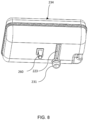
FIG. 8 illustrates a surge tank of the thermal management module ofFIG. 2 . - It must be noted that the figures disclose the invention in a detailed enough way to be implemented, said figures helping to better define the invention if needs be. The invention should however not be limited to the embodiment disclosed in the description.
- Embodiments of the present invention, explained in the forthcoming description and the accompanying drawings, relate to a simple and efficient thermal management module for motor vehicles, such as electric and/or hybrid vehicles. A fluid hub/coolant hub of the thermal management module includes a monobloc housing body having one or more fluid loops and fluid connectors configured in fluidic connection with the fluid loops, which can obviate the drawbacks of the conventional fluid hub having two plastic housing components that are connected through the complex plastic welding process. Thus, the disclosed thermal management module eliminate the need of second housing main plastic component therefore eliminating the need of complex plastic welding process as well as specific tools and/or machines required for the plastic welding resulting in reduction of manufacturing cost and the manufacturing time. In addition, the size/volume of the fluid hub is reduced which require less space for packaging and less coolant/fluid volume is required for same functionality of the conventional fluid hub.
- Although, embodiments of the present invention are explained with an example of a thermal management module for the vehicles, however, the concept of the present invention or the thermal management module of present invention is applicable for use in vehicular as well as non-vehicular environment, and all such applications are within scope of the present invention without any limitations whatsoever.
- Referring to
FIG. 2 to FIG. 5 , in accordance with an embodiment, the present invention discloses athermal management module 200 for a vehicle, such as but not limited to electric vehicles and/or hybrid vehicles, which includes afluid hub 202, one or more fluid pumps, such as fluid pumps 208-1 and 208-2 configured in fluidic connection with thefluid hub 202, and at least one heat exchanger, such as achiller 210, configured with thefluid hub 202. Thefluid hub 202 comprises amonobloc housing body 212 having one or morefluid loops 214 andfluid connectors 216 configured in fluidic connection with thefluid loops 214 and projected outside of the monobloc housing body 212 (hereinafter also referred to as "housing body" for simplicity). Thefluid loops 214 can be internal fluid passages defined in thehousing body 212. In addition, thethermal management module 200 includes avalve mechanism 206 received in achamber 204 of thefluid hub 202, which can selectively direct and/or regulate the fluid/coolant received in achamber 204 to the fluid loops/fluid connectors 216 and/or theheat exchanger 210. For instance, thefluid connectors 216, also called quick connectors, can be quickly connected with a hose/pipe. - The
valve mechanism 206 includes one ormore valves 205 is controlled by a control unit/actuator 207 of thevalve mechanism 206 and is adapted to selectively regulate fluid flow through the internal fluid flow passages/fluid loops 214. Thevalve actuator 207 is mounted on the housing body through avalve cover 209. For instance, thevalve mechanism 206 can be a multiway solenoid valve mechanism. - In addition, the
housing body 212 is made of a polymeric material. For instance, thehousing body 212 can be made of one or more plastics, thermoplastic material, a duroplastic material, a compound material, such as a thermoplastic and duroplastic compound material, at least one polypropylene material and/or at least one polyamide material. For instance, themonobloc housing body 212 is formed through the injection molding process. - In addition, mounting legs 224-1 and 224-2 are protruded from two opposite sides of the
monobloc housing body 212 to secure themonobloc housing body 212 to theopposite side plates heat exchanger 210 using mounting bolts 226-1 and 226-2, and mounting blocks 228-1 and 228-2. The mounting blocks 228-1 and 228-2 are secured on theheat exchanger 210. The mounting bolts 226-1 and 226-2 are adapted to be screwed through mounting holes of corresponding the mounting legs 224-1 and 224-2 and the mounting blocks 228-1 and 228-2 provided on theside plates heat exchanger 210. Thus, thefluid hub 202 is secured to theheat exchanger 210 from two opposite sides, particularly to the twoopposite side plates - Furthermore,
brackets 250 are provided with theheat exchanger 210 to mount thethermal management module 200 on a frame, for instance a vehicle frame. Each of thebrackets 250 includes a mountinghole 252 and an anti-vibration grommet/rubber vibration damper 254. Thus, theheat exchanger 210 can act as a structural element of themonobloc housing body 212. - Referring to
FIG. 6 to FIG. 8 , thehousing body 212 comprises afirst housing portion 232 defining thechamber 204 to accommodate the one ormore valves 205 of thevalve mechanism 206. Thefirst housing portion 232 is fluidically connected to asurge tank 234 through afirst conduit 236 that receive afluid connector 231 protruded from thesurge tank 234. More specifically, thefirst housing portion 232 receives fluid stored in thesurge tank 234 and selectively supplies fluid to theheat exchanger 210 and/or other components based on the operative configuration of thevalves 205 and/orvalve mechanism 206 of thefluid hub 202. In addition, afirst mounting arm 256 is protruded from thefirst housing portion 232 to detachably secure thesurge tank 234 to thefirst housing portion 232. Thefirst mounting arm 256 comprises anopening 258 to detachably engage with alocking hook 260 protruded from thesurge tank 234. For instance, the lockinghook 260 and the first mountingarm 256 can be in snap locking connection. Besides, a mountingplate 259 is protruded from thefirst housing portion 232, particularly from an outer surface of afluid inlet passage 241. When thesurge tank 234 is fitted on thehousing body 212, the mountingplate 259 is received in agroove 223 provided on thesurge tank 234. In addition, thefluid inlet passage 241 is configured in fluidic connection with thechamber 204 and thefirst conduit 236. - Further, the
housing body 212 includes asecond housing portion 238 fluidically connected to thefirst housing portion 232 through asecond conduit 240, and athird housing portion 242 fluidically connected to thefirst housing portion 232 through athird conduit 244. Thesecond housing portion 238 and thethird housing portion 242 are configured on two opposite sides of thefirst housing portion 232 along a first axis, called the transverse axis, of thehousing body 212. Thesecond housing portion 238 is configured to receive the fluid pump 208-1, and thethird housing portion 242 is configured to receive the fluid pump 208-2. The pumps 208-1 and 208-2 can be radial pumps. - In another embodiment, the
second housing portion 238 and thethird housing portion 242 can be configured on same side. - In addition, one or more second mounting
arms 262 are protruded from thesecond housing portion 238 to detachably secure the respective fluid pump 208-1 to thesecond housing portion 238. Each of the second mountingarms 262 comprises a mountinghole 263. Threadedbolts 261a are screwed through corresponding mountingholes 208a in the pump 208-1 and the mountingholes 263 in the second mountingarms 262 to secure the pump 208-1 to thesecond housing portion 238. Similarly, one or more third mountingarms 264 are protruded from thethird housing portion 242 to detachably secure the respective fluid pump 208-2 to thethird housing portion 242. Each of the third mountingarms 264 comprises a mountinghole 265. Threadedbolts 261b are screwed through the mountingholes 208b in the pump 208-2 and the mountingholes 265 of the third mountingarms 264 to secure the pump 208-2 to thethird housing portion 242. - In addition, the
housing body 212 further includes fluid connection terminals 246-1 and 246-2, external to thehousing body 212, on thesecond housing portion 238 and thethird housing portion 242. The fluid connection terminal 246-1 is fluidically connected to thesecond housing portion 238 and the other fluid connection terminal 246-2 is fluidically connected to thethird housing portion 242. The fluid connection terminals 246-1 and 246-2 can be used for the inlet or outlet of the pumps 208-1 and 208-2. - In addition, the
third housing portion 242 can be fluidically connected to theheat exchanger 210 through atube 248, as shown inFIG. 2 . Thetube 248 can be connected between the fluid connection terminal 246-2 and a fluid connection terminal of theheat exchanger 210. - In any case, the invention cannot and should not be limited to the embodiments specifically described in this document, as other embodiments might exist. The invention shall spread to any equivalent means and any technically operating combination of means.
Claims (15)
- A thermal management module (200) comprising:a fluid hub (202) comprising a chamber (204) to receive a valve mechanism (206);one or more fluid pumps (208-1, 208-2) configured in fluidic connection with the fluid hub (202); andat least one heat exchanger (210) configured with the fluid hub (202);wherein the fluid hub (202) comprises a monobloc housing body (212) having one or more fluid loops (214) and fluid connectors (216) configured in fluidic connection with the fluid loops (214) and projected outside of the monobloc housing body (212).
- The thermal management module (200) as claimed in the preceding claim, wherein the monobloc housing body (212) comprises a first housing portion (232) defining the chamber (204) to accommodate the valve mechanism (206) and fluidically connected to a surge tank (234) through a first conduit (236), a second housing portion (238) fluidically connected to the first housing portion (232) through a second conduit (240), and a third housing portion (242) fluidically connected to the first housing portion (232) through a third conduit (244).
- The thermal management module (200) as claimed in any of the preceding claims, wherein the first housing portion (232) comprises a fluid inlet passage (241) configured in fluidic connection with the chamber (204) and the first conduit (236).
- The thermal management module (200) as claimed in any of the preceding claims, wherein the second housing portion (238) and the third housing portion (242) are configured to receive the one or more fluid pumps (208-1, 208-2), and wherein the second housing portion (238) and the third housing portion (242) are configured on two opposite sides of the first housing portion (232).
- The thermal management module (200) as claimed in any of the preceding claims, wherein each of the second housing portion (238) and the third housing portion (242) comprises at least one fluid connection terminal (246-1, 246-2).
- The thermal management module (200) as claimed in any of the preceding claims, wherein the second housing portion (238) is fluidically connected to the heat exchanger (210) through a tube (248).
- The thermal management module (200) as claimed in any of the preceding claims, wherein the monobloc housing body (212) further comprises at least one first mounting arm (256) protruded from the first housing portion (232) to detachably secure the surge tank (234) to the first housing portion (232), wherein the first mounting arm (256) comprises an opening (258) to detachably engage with a locking hook (260) protruded from the surge tank (234).
- The thermal management module (200) as claimed in any of the preceding claims, wherein the monobloc housing body (212) further comprises one or more second mounting arms (262) protruded from the second housing portion (238) to detachably secure the respective fluid pump (208-1) to the second housing portion (238), wherein each of the second mounting arms (262) comprises a mounting hole (263).
- The thermal management module (200) as claimed in any of the preceding claims, wherein the monobloc housing body (212) further comprises one or more third mounting arms (264) protruded from the third housing portion (242) to detachably secure the respective fluid pump (208-2) to the third housing portion (242), wherein each of the third mounting arms (264) comprises a mounting hole (265).
- The thermal management module (200) as claimed in any of the preceding claims further comprises brackets (250) secured to the heat exchanger (210) to mount the thermal management module (200) on a frame, wherein each of the brackets (250) comprises a mounting hole (252) with an anti-vibration grommet (254).
- The thermal management module (200) as claimed in the preceding claim, wherein the monobloc housing body (212) is made of polymeric material, and wherein the monobloc housing body (212) is formed through an injection molding process.
- The thermal management module (200) as claimed in any of the preceding claims, wherein the monobloc housing body (212) is coupled to at least one side plate (220, 222) of the heat exchanger (210) through at least one mounting leg (224-1, 224-2) protruded from the monobloc housing body (212) and at least one mounting bolt (226-1, 226-2) screwed through mounting holes of the mounting leg (224-1, 224-2) and at least one mounting block (228-1, 228-2) secured on the heat exchanger (210).
- The thermal management module (200) as claimed in any of the preceding claims, wherein the valve mechanism (206) is adapted to selectively distribute the fluid to the fluid connectors (216) and the heat exchanger (210).
- The thermal management module (200) as claimed in any of the preceding claims, wherein the heat exchanger (210) is a chiller.
- A vehicle comprising a thermal management module (200) according to any of the preceding claim.
Priority Applications (2)
| Application Number | Priority Date | Filing Date | Title |
|---|---|---|---|
| EP23197039.3A EP4523932A1 (en) | 2023-09-13 | 2023-09-13 | A thermal management module for a vehicle |
| PCT/EP2024/075232 WO2025056528A1 (en) | 2023-09-13 | 2024-09-10 | A thermal management module for a vehicle |
Applications Claiming Priority (1)
| Application Number | Priority Date | Filing Date | Title |
|---|---|---|---|
| EP23197039.3A EP4523932A1 (en) | 2023-09-13 | 2023-09-13 | A thermal management module for a vehicle |
Publications (1)
| Publication Number | Publication Date |
|---|---|
| EP4523932A1 true EP4523932A1 (en) | 2025-03-19 |
Family
ID=88020812
Family Applications (1)
| Application Number | Title | Priority Date | Filing Date |
|---|---|---|---|
| EP23197039.3A Withdrawn EP4523932A1 (en) | 2023-09-13 | 2023-09-13 | A thermal management module for a vehicle |
Country Status (2)
| Country | Link |
|---|---|
| EP (1) | EP4523932A1 (en) |
| WO (1) | WO2025056528A1 (en) |
Citations (5)
| Publication number | Priority date | Publication date | Assignee | Title |
|---|---|---|---|---|
| CN212979863U (en) * | 2020-08-14 | 2021-04-16 | 认知控管株式会社 | Cooling water comprehensive heat management device for vehicle |
| US20210219466A1 (en) * | 2020-01-13 | 2021-07-15 | Hyundai Motor Company | Coolant supplying module |
| WO2022135510A1 (en) * | 2020-12-23 | 2022-06-30 | 浙江三花汽车零部件有限公司 | Fluid management apparatus and heat management system |
| WO2022266945A1 (en) * | 2021-06-24 | 2022-12-29 | 浙江吉利控股集团有限公司 | Multi-channel cooling line integration apparatus, thermal management integration module and electric vehicle |
| WO2023090907A1 (en) * | 2021-11-19 | 2023-05-25 | 한온시스템 주식회사 | Water supply module |
-
2023
- 2023-09-13 EP EP23197039.3A patent/EP4523932A1/en not_active Withdrawn
-
2024
- 2024-09-10 WO PCT/EP2024/075232 patent/WO2025056528A1/en active Pending
Patent Citations (5)
| Publication number | Priority date | Publication date | Assignee | Title |
|---|---|---|---|---|
| US20210219466A1 (en) * | 2020-01-13 | 2021-07-15 | Hyundai Motor Company | Coolant supplying module |
| CN212979863U (en) * | 2020-08-14 | 2021-04-16 | 认知控管株式会社 | Cooling water comprehensive heat management device for vehicle |
| WO2022135510A1 (en) * | 2020-12-23 | 2022-06-30 | 浙江三花汽车零部件有限公司 | Fluid management apparatus and heat management system |
| WO2022266945A1 (en) * | 2021-06-24 | 2022-12-29 | 浙江吉利控股集团有限公司 | Multi-channel cooling line integration apparatus, thermal management integration module and electric vehicle |
| WO2023090907A1 (en) * | 2021-11-19 | 2023-05-25 | 한온시스템 주식회사 | Water supply module |
Also Published As
| Publication number | Publication date |
|---|---|
| WO2025056528A1 (en) | 2025-03-20 |
Similar Documents
| Publication | Publication Date | Title |
|---|---|---|
| KR102721560B1 (en) | Heater Module For Heating Cooling Water | |
| US8286615B2 (en) | Intake manifold of an internal combustion engine and cooling fluid charge air cooler | |
| EP1482175B1 (en) | Electric powered pump | |
| US20190322155A1 (en) | Heater module for heating cooling water | |
| US20110123370A1 (en) | Electric water pump | |
| US12139005B2 (en) | Component node and a component carrier for the component node | |
| CN110661061A (en) | Battery system for vehicle | |
| US20250010692A1 (en) | Electric compressor for vehicle and heat exchanger module including the same | |
| US12366196B2 (en) | Component housing unit and a vehicle thermal management system comprising a component housing unit | |
| US11614024B2 (en) | Reservoir tank assembly for vehicle | |
| US20250222760A1 (en) | Cooling module | |
| US20250020229A1 (en) | Cooling module | |
| US20240317017A1 (en) | Thermal management system | |
| KR102439104B1 (en) | All-in-one vehicle coolant heating module | |
| EP4523932A1 (en) | A thermal management module for a vehicle | |
| US8459337B2 (en) | Apparatus including a heat exchanger and equalizing vessel | |
| EP4520557A1 (en) | A thermal management module for a vehicle | |
| EP1614904B1 (en) | Hydraulic system with reservoir and pump suction enhancer for motor vehicle | |
| US20250012368A1 (en) | Flow-Path Switching Device, Electromagnetic Valve Used Therein, and Cooling UnitProgram, And Optical Measurement Device | |
| US11982364B2 (en) | Valve for a fluid system and fluid system for a vehicle | |
| CN119812556A (en) | Cooling system manifold for battery modules | |
| WO2020212894A1 (en) | Support and connection device | |
| EP4653701A1 (en) | Coolant hub with integrated pump housing | |
| EP4653700A1 (en) | Coolant hub with integrated axis | |
| US20250387982A1 (en) | Manifold and method for manufacturing manifold |
Legal Events
| Date | Code | Title | Description |
|---|---|---|---|
| PUAI | Public reference made under article 153(3) epc to a published international application that has entered the european phase |
Free format text: ORIGINAL CODE: 0009012 |
|
| STAA | Information on the status of an ep patent application or granted ep patent |
Free format text: STATUS: THE APPLICATION HAS BEEN PUBLISHED |
|
| AK | Designated contracting states |
Kind code of ref document: A1 Designated state(s): AL AT BE BG CH CY CZ DE DK EE ES FI FR GB GR HR HU IE IS IT LI LT LU LV MC ME MK MT NL NO PL PT RO RS SE SI SK SM TR |
|
| STAA | Information on the status of an ep patent application or granted ep patent |
Free format text: STATUS: THE APPLICATION IS DEEMED TO BE WITHDRAWN |
|
| 18D | Application deemed to be withdrawn |
Effective date: 20250920 |