EP4523921A1 - Image forming system - Google Patents
Image forming system Download PDFInfo
- Publication number
- EP4523921A1 EP4523921A1 EP24200005.7A EP24200005A EP4523921A1 EP 4523921 A1 EP4523921 A1 EP 4523921A1 EP 24200005 A EP24200005 A EP 24200005A EP 4523921 A1 EP4523921 A1 EP 4523921A1
- Authority
- EP
- European Patent Office
- Prior art keywords
- toner image
- adhesive toner
- bonding
- booklet
- recording material
- Prior art date
- Legal status (The legal status is an assumption and is not a legal conclusion. Google has not performed a legal analysis and makes no representation as to the accuracy of the status listed.)
- Granted
Links
Images




Classifications
-
- G—PHYSICS
- G03—PHOTOGRAPHY; CINEMATOGRAPHY; ANALOGOUS TECHNIQUES USING WAVES OTHER THAN OPTICAL WAVES; ELECTROGRAPHY; HOLOGRAPHY
- G03G—ELECTROGRAPHY; ELECTROPHOTOGRAPHY; MAGNETOGRAPHY
- G03G15/00—Apparatus for electrographic processes using a charge pattern
- G03G15/65—Apparatus which relate to the handling of copy material
- G03G15/6538—Devices for collating sheet copy material, e.g. sorters, control, copies in staples form
- G03G15/6541—Binding sets of sheets, e.g. by stapling, glueing
- G03G15/6544—Details about the binding means or procedure
-
- B—PERFORMING OPERATIONS; TRANSPORTING
- B42—BOOKBINDING; ALBUMS; FILES; SPECIAL PRINTED MATTER
- B42C—BOOKBINDING
- B42C9/00—Applying glue or adhesive peculiar to bookbinding
- B42C9/0081—Applying glue or adhesive peculiar to bookbinding applying adhesive to individual sheets for binding them together
-
- B—PERFORMING OPERATIONS; TRANSPORTING
- B42—BOOKBINDING; ALBUMS; FILES; SPECIAL PRINTED MATTER
- B42C—BOOKBINDING
- B42C1/00—Collating or gathering sheets combined with processes for permanently attaching together sheets or signatures or for interposing inserts
- B42C1/12—Machines for both collating or gathering and permanently attaching together the sheets or signatures
-
- B—PERFORMING OPERATIONS; TRANSPORTING
- B42—BOOKBINDING; ALBUMS; FILES; SPECIAL PRINTED MATTER
- B42C—BOOKBINDING
- B42C9/00—Applying glue or adhesive peculiar to bookbinding
- B42C9/0093—Applying glue or adhesive peculiar to bookbinding by fusing, welding sheets together
-
- B—PERFORMING OPERATIONS; TRANSPORTING
- B65—CONVEYING; PACKING; STORING; HANDLING THIN OR FILAMENTARY MATERIAL
- B65H—HANDLING THIN OR FILAMENTARY MATERIAL, e.g. SHEETS, WEBS, CABLES
- B65H37/00—Article or web delivery apparatus incorporating devices for performing specified auxiliary operations
- B65H37/04—Article or web delivery apparatus incorporating devices for performing specified auxiliary operations for securing together articles or webs, e.g. by adhesive, stitching or stapling
-
- B—PERFORMING OPERATIONS; TRANSPORTING
- B65—CONVEYING; PACKING; STORING; HANDLING THIN OR FILAMENTARY MATERIAL
- B65H—HANDLING THIN OR FILAMENTARY MATERIAL, e.g. SHEETS, WEBS, CABLES
- B65H39/00—Associating, collating, or gathering articles or webs
- B65H39/10—Associating articles from a single source, to form, e.g. a writing-pad
-
- B—PERFORMING OPERATIONS; TRANSPORTING
- B65—CONVEYING; PACKING; STORING; HANDLING THIN OR FILAMENTARY MATERIAL
- B65H—HANDLING THIN OR FILAMENTARY MATERIAL, e.g. SHEETS, WEBS, CABLES
- B65H2301/00—Handling processes for sheets or webs
- B65H2301/50—Auxiliary process performed during handling process
- B65H2301/51—Modifying a characteristic of handled material
- B65H2301/516—Securing handled material to another material
- B65H2301/5161—Binding processes
- B65H2301/51614—Binding processes involving heating element
-
- B—PERFORMING OPERATIONS; TRANSPORTING
- B65—CONVEYING; PACKING; STORING; HANDLING THIN OR FILAMENTARY MATERIAL
- B65H—HANDLING THIN OR FILAMENTARY MATERIAL, e.g. SHEETS, WEBS, CABLES
- B65H2701/00—Handled material; Storage means
- B65H2701/10—Handled articles or webs
- B65H2701/19—Specific article or web
- B65H2701/1932—Signatures, folded printed matter, newspapers or parts thereof and books
-
- B—PERFORMING OPERATIONS; TRANSPORTING
- B65—CONVEYING; PACKING; STORING; HANDLING THIN OR FILAMENTARY MATERIAL
- B65H—HANDLING THIN OR FILAMENTARY MATERIAL, e.g. SHEETS, WEBS, CABLES
- B65H2801/00—Application field
- B65H2801/03—Image reproduction devices
-
- B—PERFORMING OPERATIONS; TRANSPORTING
- B65—CONVEYING; PACKING; STORING; HANDLING THIN OR FILAMENTARY MATERIAL
- B65H—HANDLING THIN OR FILAMENTARY MATERIAL, e.g. SHEETS, WEBS, CABLES
- B65H2801/00—Application field
- B65H2801/24—Post -processing devices
-
- B—PERFORMING OPERATIONS; TRANSPORTING
- B65—CONVEYING; PACKING; STORING; HANDLING THIN OR FILAMENTARY MATERIAL
- B65H—HANDLING THIN OR FILAMENTARY MATERIAL, e.g. SHEETS, WEBS, CABLES
- B65H2801/00—Application field
- B65H2801/48—Bookbinding
-
- G—PHYSICS
- G03—PHOTOGRAPHY; CINEMATOGRAPHY; ANALOGOUS TECHNIQUES USING WAVES OTHER THAN OPTICAL WAVES; ELECTROGRAPHY; HOLOGRAPHY
- G03G—ELECTROGRAPHY; ELECTROPHOTOGRAPHY; MAGNETOGRAPHY
- G03G2215/00—Apparatus for electrophotographic processes
- G03G2215/00362—Apparatus for electrophotographic processes relating to the copy medium handling
- G03G2215/00789—Adding properties or qualities to the copy medium
- G03G2215/00822—Binder, e.g. glueing device
- G03G2215/00835—Toner binding
-
- G—PHYSICS
- G03—PHOTOGRAPHY; CINEMATOGRAPHY; ANALOGOUS TECHNIQUES USING WAVES OTHER THAN OPTICAL WAVES; ELECTROGRAPHY; HOLOGRAPHY
- G03G—ELECTROGRAPHY; ELECTROPHOTOGRAPHY; MAGNETOGRAPHY
- G03G2215/00—Apparatus for electrophotographic processes
- G03G2215/00362—Apparatus for electrophotographic processes relating to the copy medium handling
- G03G2215/00789—Adding properties or qualities to the copy medium
- G03G2215/00822—Binder, e.g. glueing device
- G03G2215/00848—Details of binding device
-
- G—PHYSICS
- G03—PHOTOGRAPHY; CINEMATOGRAPHY; ANALOGOUS TECHNIQUES USING WAVES OTHER THAN OPTICAL WAVES; ELECTROGRAPHY; HOLOGRAPHY
- G03G—ELECTROGRAPHY; ELECTROPHOTOGRAPHY; MAGNETOGRAPHY
- G03G2215/00—Apparatus for electrophotographic processes
- G03G2215/00362—Apparatus for electrophotographic processes relating to the copy medium handling
- G03G2215/00919—Special copy medium handling apparatus
- G03G2215/00936—Bookbinding
Definitions
- the present invention relates to an image forming system including a booklet generation apparatus that generates a booklet by applying heat and pressure to an adhesive toner formed on a plurality of recording materials and bonding the plurality of recording materials together.
- the image forming apparatus including the booklet generation apparatus as discussed in Japanese Patent Application Laid-Open No. 2010-111025 may worsen the appearance and quality of a booklet for the following reasons.
- recording materials set in a sheet feed cassette by a user are not regulated properly in a width direction depending on the force applied by the user and each recording material is fed and conveyed in a state of being misaligned in the width direction.
- the recording materials may be misaligned due to various causes during bonding.
- a booklet may be generated with an adhesive toner image formed at a misaligned position on each recording material.
- the adhesive toner image for bonding inner recording materials of the booklet may become transparently visible outside the adhesive toner image bonding the front or back cover, which worsens the appearance and quality of the booklet.
- the present invention is directed to preventing the appearance and quality of a booklet from worsening even in a case where an adhesive toner image is formed at a misaligned position on each recording material.
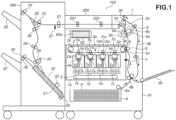
- Fig. 1 is a schematic diagram illustrating a cross section of an image forming apparatus 1 and a booklet generation apparatus 300 according to the first embodiment.
- the image forming apparatus 1 and the booklet generation apparatus 300 together form an image forming system 100.
- the image forming system 100 may include a configuration in which a booklet generation function is partially or entirely embedded in the image forming apparatus 1.
- the image forming apparatus 1 includes a recording material cassette 8, a top sensor 4, an image forming unit 1e, a fixing device 6, and a housing 19.
- the recording material cassette 8 stores recording materials.
- the top sensor 4 is a unit that detects leading edges of recording materials.
- the image forming unit 1e is an image forming unit.
- the fixing device 6 is a fixing unit.
- the housing 19 encloses the recording material cassette 8, the top sensor 4, the image forming unit 1e, and the fixing device 6.
- the image forming apparatus 1 has a printing function to generate a printed material by forming a toner image on a recording material P fed from the recording material cassette 8 using the image forming unit 1e and fixing the toner image to the recording material P using the fixing device 6.
- a maximum size at which an image can be formed on a recording material P is A4 size (length 297 mm ⁇ width 210 mm), and image forming is performed by conveying an A4-sized recording material P in a lengthwise direction.
- the recording material cassette 8 is inserted in a lower portion of the image forming apparatus 1 so that the recording material cassette 8 can be pulled out of the housing 19, and a plurality of recording materials P is stored in the recording material cassette 8.
- the recording material cassette 8 includes a regulating plate (not illustrated), and the regulating plate regulates a recording material width direction (a direction perpendicular to a conveyance direction on a recording material surface) that can be operated by a user.
- a recording material P stored in the recording material cassette 8 is fed from the recording material cassette 8 by a sheet feed roller 8a, which is a sheet feed portion, and conveyed by a pair of conveyance rollers 8b. Further, recording materials set on a multi-tray 20 may be fed singly.
- the top sensor 4 includes a flag for detecting leading edges of recording materials, and a toner image forming start position where the image forming unit 1e starts forming a toner image is corrected based on the detection results of the flag.
- the image forming unit 1e is a tandem type electrophotographic unit including four process cartridges 7k, 7y, 7m, and 7c, a scanner unit 2, and a transfer unit 3.
- a process cartridge refers to a replaceable integrated unit containing a plurality of components for an image forming process.
- the process cartridges 7k, 7y, 7m, and 7c have substantially the same structure, except for the types of powder stored in four powder storage portions Gk, Gy, Gm, and Gc.
- the process cartridges 7k, 7y, 7m, and 7c respectively include photosensitive drums Dk, Dy, Dm, and Dc, charging rollers Ck, Cy, Cm, and Cc, and the powder storage portions Gk, Gy, Gm, and Gc.
- the photosensitive drums Dk, Dy, Dm, and Dc are image bearing members, and the charging rollers Ck, Cy, Cm, and Cc are charging devices.
- the powder storage portions Gk, Gy, Gm, and Gc store powder and supply the powder to the photosensitive drums Dk, Dy, Dm, and Dc.
- the four powder storage portions Gk, Gy, Gm, and Gc respectively store black, yellow, magenta, and cyan toners Tk, Ty, Tm, and Tc as toners for forming visible images on recording materials P.
- the fixing device 6 is a fixing unit for heating the toner images on the recording material P, melting the toner images, and fixing the toner images and is situated above the secondary transfer roller 5.
- the fixing device 6 is a fixing device that uses a heat fixing method and includes a heating film 6b and a pressing roller 6c.
- the heating film 6b is a fixing member that heats using a ceramic heater 6a as a heat source, and the pressing roller 6c is a pressing member.
- the heating film 6b may heat using a halogen lamp or a heat generation mechanism using an induction heating method.
- thermoplastic resin as a binder resin
- resins that can be used in the thermoplastic resin are not particularly limited, and resins that are used in conventional toners for printing may be used, such as polyester resin, vinyl resin, acrylic resin, or styrene-acrylic resin. More than one of the resins described above may be contained.
- the toners for printing may contain colorants, magnetic materials, charge control agents, waxes, and/or external additives.
- a control unit (not illustrated) of the image forming apparatus 1 starts a series of operations (image forming operation) to convey a recording material P and form an image on the recording material P.
- image forming operation first, a recording material P is singly fed from the recording material cassette 8 and conveyed along the top sensor 4 via the pair of conveyance rollers 8b to the transfer nip 5n. While passing along the top sensor 4, the recording material P pushes down the flag of the top sensor 4 in the conveyance direction, and based on this, the control unit detects whether the leading edge of the recording material P has passed, and an image forming start position is determined based on the detection results.
- the electrostatic latent images on the photosensitive drums Dk, Dy, Dm, and Dc are developed into toner images using the powders borne on development rollers Hk, Hy, Hm, and Hc in the powder storage portions Gk, Gy, Gm, and Gc of the process cartridges 7k, 7y, 7m, and 7c.
- the transfer belt 3a rotates anti-clockwise (arrow v) in Fig. 1 .
- Toner images formed by the process cartridges 7k, 7y, 7m, and 7c are primarily transferred from the photosensitive drums Dk, Dy, Dm, and Dc onto the transfer belt 3a by an electric field formed between the photosensitive drums Dk, Dy, Dm, and Dc and the primary transfer rollers Fk, Fy, Fm, and Fc.
- the toner images borne on the transfer belt 3a are secondarily transferred onto the conveyed recording material P by an electric field formed between the secondary transfer roller 5 and the inner secondary transfer roller 3b.
- the toner Tk is used to bond recording materials together, and an image after the secondary transfer of the toner Tk to the recording material P will be referred to as "adhesive toner image Ta".
- the present embodiment is not limited to that described above, and the adhesive toner image Ta may be formed using the toner Ty, Tm, or Tc other than the toner Tk or may be formed by overlaying several of the toners Tk, Ty, Tm, and Tc.
- the recording material P is conveyed to the fixing device 6 and undergoes a fixing process. Specifically, while the recording material P passes through the fixing nip 6n, the toner images on the recording material P are heated and pressed to cause the toners Ty, Tm, and Tc for printing and the adhesive toner image Ta to melt and thereafter solidify, whereby an image fixed to the recording material P is obtained.
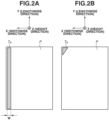
- Figs. 2A and 2B illustrate predetermined image regions of the adhesive toner image Ta according to the present embodiment. As illustrated in Fig. 2A , by forming the adhesive toner image Ta (hatched portion) in a lengthwise edge portion of the recording material P, a long-edge bound booklet is generated as an output of the booklet generation by the booklet generation apparatus 300.
- the adhesive toner image Ta herein has a width W of 4.0 mm. Further, as illustrated in Fig. 2B , by forming the adhesive toner image Ta in a corner portion formed by longer and shorter sides of the recording material P, a corner bound booklet is generated as an output. A form of generating a long-edge bound booklet according to the first embodiment will be described below.
- a switching guide 33 is a flap-shaped guide member for switching the conveyance direction based on a selected mode in a case where one of a one-sided printing mode in which an image is formed on one side of a recording material P and a two-sided printing mode in which an image is formed on both sides of a recording material P is selected. In the case of the one-sided printing mode, the switching guide 33 conveys the recording material P to a pair of discharge rollers 34.
- the switching guide 33 conveys the recording material P to a pair of switchback rollers 35, and after the trailing edge of the recording material P is discharged, the rotation direction of the pair of switchback rollers 35 is reversed to convey the recording material P to a two-sided conveyance path 36 for two-sided printing.
- the recording material P conveyed to the two-sided conveyance path 36 passes through the secondary transfer portion and the fixing unit again so that an image is formed on an unprinted surface of the recording material P, and the switching guide 33 eventually conveys the recording material P to the pair of discharge rollers 34.
- an operation panel 50 is on the outside of the housing 19 and includes a liquid crystal display unit 50a, and the user can view the liquid crystal display unit 50a and perform touch operations on the liquid crystal display unit 50a.
- An operating status of the image forming apparatus 1 and a status of consumables such as toners are displayed on the liquid crystal display unit 50a of the operation panel 50 by the control unit, and the liquid crystal display unit 50a has a navigation function to guide the user through specific operations.
- the recording material P having undergone the image forming by the image forming apparatus 1 is conveyed to the booklet generation apparatus 300 via an intermediate conveyance unit 200 including pairs of conveyance rollers 201 and 202.
- the booklet generation apparatus 300 is a floor standing type and includes a recording material alignment unit and a thermal compression bonding unit 51 in its lower portion.
- the thermal compression bonding unit 51 is a heating and pressing unit that heats and presses a bundle of aligned recording materials for a predetermined time.
- the recording material P conveyed from the intermediate conveyance unit 200 is passed to a pair of conveyance rollers 21 of the booklet generation apparatus 300. Based on a time at which the trailing edge passes through an entrance sensor 27, a pair of conveyance rollers 22 accelerates the recording material P at a predetermined timing. In a case where the recording material P is to be discharged to an upper discharge tray 25, once the trailing edge of the recording material P reaches between the pair of conveyance rollers 22 and reverse rollers 24, the recording material P is decelerated to a predetermined discharge speed and is discharged to the upper discharge tray 25.
- an output destination of the recording material P is a lower discharge tray 37.
- a non-return valve 23 biased clockwise by a spring temporarily stops conveying the recording material P at the timing when the trailing edge of the recording material P exits, and thereafter the non-return valve 23 switches the recording material P back and conveys the recording material P to inner discharge rollers 26.
- the recording material P conveyed from the inner discharge rollers 26 is conveyed to kick-out rollers 29 via intermediate conveyance rollers 28 and conveyed to an intermediate stacking unit 42.
- intermediate stacking unit 42 At the bottommost part of the intermediate stacking unit 42, lengthwise alignment reference plates 39 are placed, and the bundle of recording materials P is aligned by pressing end portions of the recording materials P in the conveyance direction against the lengthwise alignment reference plates 39.
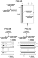
- a method of aligning the recording materials P will be described below with reference to Figs. 3A to 3D .
- Widthwise, lengthwise, and height directions of the recording materials P will be referred to X, Y, and Z directions, respectively.
- a semicircular roller (alignment roller) 32 for pushing the recording materials P exited from the kick-out rollers 29 against the lengthwise alignment reference plates 39 is supported to rotate freely in the intermediate stacking unit 42.
- the semicircular roller 32 conveys the recording materials P to the lengthwise alignment reference plates 39 at a predetermined timing.
- a conveyance pressure of the semicircular roller 32 is controlled to a particular pressure so that after the recording materials P are pressed against the lengthwise alignment reference plates 39, the semicircular roller 32 slips on the recording material P.
- a bundle pressing flag 30 for preventing the trailing edge of the recording material P from lifting as illustrated in Fig. 1 is supported downstream of the kick-out rollers 29 to rotate freely so that the trailing edge of the recording material P stacked in the intermediate stacking unit 42 and the leading edge of the subsequent recording material P do not interfere with each other.
- the thermal compression bonding unit 51 as a recording material bonding unit performs a heating and pressing process.
- the thermal compression bonding unit 51 performs the heating and pressing process on the plurality of recording materials P to generate a bundle of recording materials P.
- the thermal compression bonding unit 51 performs the heating and pressing process on the bundle of recording materials P aligned in the lengthwise and widthwise directions to thereby generate a bundle of recording materials P (booklet).
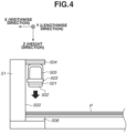
- Fig. 4 is a cross-sectional view illustrating the thermal compression bonding unit 51.
- the thermal compression bonding unit 51 places a heating plate 502 in contact with a surface of a ceramic heater 501.
- the heating plate 502 is made of aluminum and has a thickness of 1.5 mm
- the ceramic heater 501 includes a heat generation member as a heating source and has a thickness of 1.0 mm.
- the temperature of the ceramic heater 501 is controlled to a target temperature of 240°C constantly by a temperature detection unit (not illustrated) and a power application unit (not illustrated) supported by a heater support member 503, whereby the surface temperature of the heating plate 502 is controlled to 200°C.
- a pressing lever 504 obtains power from a drive source (not illustrated) to press the thermal compression bonding unit 51 in the Z direction (downward direction) to apply pressure to the bundle of recording materials P.
- the pressure from the pressing lever 504 is transmitted to the bundle of recording materials P, for example, at an average surface pressure of 0.2 MPa via a metal stay 505.
- a pressure range on the bundle of recording materials P is 8.0 mm in the X direction (widthwise direction) and 300 mm in the Y direction (lengthwise direction), and the pressure center is a position of a midpoint of the pressure range in the widthwise direction.
- a receiving member 506 is a silicone rubber plate with a thickness of 2.0 mm and is a member for stably withstanding the pressure. Further, the pressure applied to the bundle of recording materials P is controlled by controlling a pressing amount of the pressing lever 504. Then, the thermal compression bonding unit 51 presses the bundle of recording materials P for, for example, 2.0 seconds and thereafter separates.
- the adhesive toner image Ta applied to the recording material P acts as an adhesive through heat melting and solidification to bond the recording materials P together. Further, according to the present embodiment, the adhesive toner image Ta is applied to the recording material P in an amount of about 0.5 mg/cm 2 , and the adhesive toner image Ta with a specific gravity of about 1.0 g/cm 3 is used.
- the booklet generation apparatus 300 generates a booklet by repeating a process of stacking a plurality of recording materials P, performing the heating and pressing process on the stacked recording materials P, stacking a plurality of recording materials P on the bundle of recording materials P having undergone the heating and pressing process, and performing the heating and pressing process. For example, in a case where five recording materials P are stacked at a time, in order to generate a booklet of 15 recording materials P, the process described above is performed three times in total.
- a bundle discharge guide (not illustrated) moves parallel from a stand-by position toward a recording material discharge port 45 to thereby push out the bundle of recording materials P.
- the recording material discharge port 45 is provided with bundle discharge rollers 38. Once the leading edges of the bundle of recording materials P reach a position slightly beyond the bundle discharge rollers 38, the bundle discharge guide stops and returns to the stand-by position. The bundle discharge rollers 38 discharge the bundle of recording materials P received from the bundle discharge guide to the lower discharge tray 37.
- the regulation on the width direction of the recording materials loosens because, for example, the user incorrectly sets the regulating plate at an unsuitable position for the size of recording materials stacked in the recording material cassette 8 or the regulating plate becomes unstable due to manufacturing tolerances.
- the recording material may be skewed and conveyed in the skewed state to the image forming portion.
- an adhesive toner image is formed at a position misaligned from the predetermined position as illustrated in Fig. 2A , and "misalignment of adhesive toner images" occurs.
- misalignment of adhesive toner images may occur even in generating, for example, a booklet of a combination of thick paper and thin paper using the multi-tray 20 and the recording material cassette 8.
- a small deviation may occur in the timing of pushing down the flag of the top sensor 4.
- the image forming start position varies between thick paper and thin paper, and misalignment of adhesive toner images may occur with respect to the conveyance direction in generating a booklet of a combination of thick paper and thin paper.
- the user is to input information indicating that a booklet is to be generated using the changed type of recording materials only for front and back covers to the booklet generation apparatus 300, or the type of the recording materials may be identified using a sensor to address the change. Further, it is assumed that one type of recording materials is used in one booklet, and even in a case where different types of recording materials are used for different booklets, the possibility that the deviation in the timing to push down the flag of the top sensor 4 varies for each booklet may be taken into consideration.
- the adhesive toner images formed on the recording materials of a booklet generated in the booklet generation apparatus 300 become misaligned.
- the booklet in which the adhesive toner images on the recording materials are misaligned is viewed from its front cover, the misaligned adhesive toner images inside the booklet are transparently visible from the front cover, which may worsen the appearance of the booklet.
- the toners used to form the adhesive toner images Ta include a color toner, the adhesive toner images Ta are often transparently visible and easily recognizable, which often has a negative impact on the booklet quality.
- an adhesive toner image has a rectangular shape and is formed so that the longer side of the rectangular shape is aligned with the longer side of the recording material as illustrated in Figs. 5A to 5C and 6 .
- the rectangular shape may be formed so that the longer side of the rectangular shape is aligned with the shorter side of the recording material.
- Figs. 5A to 5C illustrate, as a comparative example of the present embodiment, a case where adhesive toner images formed on recording materials have the same size and a booklet is generated with the adhesive toner images misaligned on the recording materials conveyed in a skewed state to the image forming portion.
- a front cover P 0 is a front cover of the booklet
- a recording material P 1 is the first recording material from the front cover of the booklet toward the inside (-Z direction)
- a recording material P 2 is the next recording material toward the inside of the booklet.
- a back cover P j is a back cover of the booklet.
- the recording materials P 1 to P j-1 are recording materials sandwiched between the front and back covers of the booklet and will therefore be referred to as middle pages, and according to the present embodiment, there are two or more middle pages.
- An adhesive toner image T 0 is an adhesive toner image for bonding the recording material P 0 , which is the front cover, and the recording material P 1 , which is a middle page, together
- an adhesive toner image T 1 is an adhesive toner image for bonding the recording materials P 1 and P 2 together.
- an adhesive toner image T j-1 is an adhesive toner image for bonding the back cover of the booklet.
- all the adhesive toner images including the adhesive toner images T 0 and T 1 formed on the recording materials have the same size with a width (X direction) of 4 mm and a length (Y direction) of 287 mm.
- FIG. 5A to 5C illustrate a case where the recording material P 1 is skewed and only the adhesive toner image T 1 formed on the recording material P 1 is misaligned, and in Figs. 5A to 5C , the adhesive toner image T 1 is misaligned from the predetermined position by a maximum of 2 mm in the widthwise direction (X direction) and a maximum of 2 mm in the lengthwise direction (Y direction).
- Fig. 5A is a diagram illustrating the generated booklet viewed from the front cover (Z direction).
- Fig. 5B is a diagram illustrating the booklet viewed from the bottom of the booklet ( ⁇ direction in Fig. 5A).
- Fig. 5C is a diagram illustrating the booklet viewed from the spine of the booklet ( ⁇ direction in Fig.
- the adhesive toner image T 0 for bonding the recording materials P 0 and P 1 together and the adhesive toner image T 1 for bonding the recording materials P 1 and P 2 together in the booklet from the recording material P 0 , which is the front cover, to the recording material P j , which is the back cover, generated by the booklet generation apparatus 300.
- the adhesive toner image T 1 is misaligned from the adhesive toner images T 0 and T j-1 in the widthwise direction (-X direction). Further, as illustrated in Fig.
- the adhesive toner image T 1 is misaligned from the adhesive toner images T 0 and T j-1 also in the lengthwise direction (Y direction). Consequently, the adhesive toner image T 1 becomes transparently visible when the adhesive toner image portion is viewed from the front cover of the booklet, which worsens the appearance of the booklet.
- the adhesive toner images including the adhesive toner images T 0 and T 1 formed on the recording materials have the same size, an occurrence of a misalignment of the adhesive toner images due to skewing worsens the appearance of the booklet.
- FIG. 6A to 6C widthwise, lengthwise, and height directions of the booklet will be referred to as X, Y, and Z directions, respectively.
- a front cover P 0 is a front cover of the booklet
- a recording material P 1 is the first recording material from the front cover of the booklet toward the inside (-Z direction)
- a recording material P 2 is the next recording material toward the inside of the booklet.
- a back cover P j is a back cover of the booklet.
- An adhesive toner image T 0 ' is an adhesive toner image for bonding the recording material P 0 , which is the front cover, and the recording material P 1 , which is a middle page, together
- an adhesive toner image T 1 is an adhesive toner image for bonding the recording materials P 1 and P 2 together.
- an adhesive toner image T j-1 is an adhesive toner image for bonding the back cover of the booklet.
- Figs. 6A to 6C illustrate a case where the recording material P 1 is skewed and only the adhesive toner image T 1 formed on the recording material P 1 is misaligned as in the comparative example illustrated in Figs. 5A to 5C .
- Figs. 6A to 6C the adhesive toner image T 1 is also misaligned from the predetermined position by a maximum of 2 mm in the widthwise direction (X direction) and a maximum of 2 mm in the lengthwise direction (Y direction).
- Fig. 6A is a diagram illustrating the generated booklet viewed from the front cover (Z direction).
- Fig. 6B is a diagram illustrating the booklet viewed from the bottom of the booklet ( ⁇ direction in Fig. 6A).
- Fig. 6C is a diagram illustrating the booklet viewed from the spine of the booklet ( ⁇ direction in Fig. 6A ).
- a feature of the present embodiment is that even in a case where there is a misalignment of the adhesive toner images, in order to maintain the appearance of the booklet, the adhesive toner image T 0 ' for bonding the front cover and the middle page together is formed to be greater in size than the adhesive toner images (T 1 to T j-1 ) for bonding the middle pages together.
- the adhesive toner image T 0 ' according to the present embodiment has a width (X direction) of 6 mm and a length (Y direction) of 289 mm.
- the width and the length are greater than the width (X direction), which is 4 mm, and the length (Y direction), which is 287 mm, of the adhesive toner images (T 1 to T j-1 ) formed on the recording materials other than the front cover of the booklet.
- the adhesive toner image T 0 ' is greater in area than the adhesive toner images (T 1 to T j-1 ) when viewed from the direction perpendicular to the surfaces of the recording materials.
- the adhesive toner image T 0 ' is formed to be longer in the widthwise direction (-X direction) than the adhesive toner images (T 1 to T j-1 ).
- the adhesive toner image T 0 ' is formed to be longer in the lengthwise direction (Y direction) than the adhesive toner images (T 1 to T j-1 ). Consequently, as illustrated in Fig.
- the adhesive toner image T 1 is not transparently visible although the adhesive toner images on the recording materials for bonding the middle pages together are misaligned when viewed from the front cover.
- the adhesive toner image for bonding the front cover and the middle page together is formed to be greater in area than the adhesive toner images for bonding the middle pages together so that even in a case where an adhesive toner image formed in the booklet is misaligned from the adhesive toner image on the front cover, the misaligned adhesive toner image is not transparently visible from the front cover, which prevents the appearance of the booklet from worsening. This is because the booklet is generated so that the adhesive toner image portions for bonding the middle pages together are entirely covered by the adhesive toner image for bonding the front cover and the middle page together when the booklet is viewed from the front cover.
- the size of the adhesive toner image T 0 ' for bonding the front cover is determined considering a maximum value of an amount of misalignment of images that may occurs in the image forming apparatus 1.
- the adhesive toner image T 0 ' is desirably large enough to cover even the maximum misalignment of images.
- the adhesive toner image T 0 ' is desirably set to the smallest possible area that still covers the entire region where misalignment of adhesive toner images may occur.
- the adhesive toner image on the front cover of the booklet is increased in length in both the lengthwise and widthwise directions of the booklet according to the present embodiment
- the image may be enlarged only in the lengthwise direction of the booklet or only in the widthwise direction of the booklet.
- a misalignment of the adhesive toner images is likely to occur in the skew direction, so that it is desirable to select a direction for increasing the length of the adhesive toner images based on the tendency.
- sensors for the measurement are installed in the booklet generation apparatus 300 or in the image forming apparatus 1 connected to the booklet generation apparatus 300.
- directions in which misalignment of adhesive toner images tends to occur and misalignment amounts are identified in advance for each type of recording materials and for each operating environment of the booklet generation apparatus 300, and the shape and size of the adhesive toner image T 0 ' on the front cover of the booklet are changed based on booklet generation conditions (types of recording materials, operating environment).
- the adhesive toner image T 0 ' on the front cover is set to the smallest possible area that still covers the entire region where misalignment of adhesive toner images may occur for each booklet generation condition (types of recording materials, operating environment).
- the adhesive toner image T 0 ' on the front cover may be set to be smaller than the region (6 mm ⁇ 289 mm) according to the present embodiment described above.
- the appearance of the booklet is prevented from worsening while reducing the adhesive toner consumption.
- the adhesive toner image T 1 is misaligned from the predetermined position by a maximum of 2 mm in the widthwise direction (-X direction) and a maximum of 2 mm in the lengthwise direction (Y direction).
- a booklet was generated using a CS-060F (manufactured by Canon) as recording materials, and misalignment of adhesive toner images transparently visible from a front cover was evaluated by measuring densities of toners transparently visible from the front cover.
- a booklet of the comparative example was placed on 10 sheets of GFC081 (manufactured by Canon) placed on top of another on a horizontal flat surface
- a booklet of the present embodiment was placed on other 10 sheets of GFC081 (manufactured by Canon) placed on top of another on a horizontal flat surface.
- the image edge portion according to the present embodiment refers to a position misaligned by 1 mm in the widthwise direction (-X direction) from an edge of the adhesive toner image T 0 bonding the front cover of the booklet as illustrated in Fig. 5A .
- the background portion according to the present embodiment refers to a region without an adhesive toner image or a toner image for printing, such as a margin portion, as illustrated in Fig. 5A .
- the image edge portion and the background portion in Fig. 6A were measured under the same conditions.
- Table 1 presents measurement results of densities of the image edge portions and the background portions of the booklets of the comparative example and the present embodiment and calculation results of differences between the densities of the image edge portions and the background portions.
- Table 1 Comparison of Densities between Present Embodiment and Comparative Example Comparative Example Present Embodiment Density of Image Edge Portion 0.14 0.07 Density of Background Portion 0.07 0.07 Difference in Density 0.07 0.00
- the density of the image edge portion is 0.14, and the density of the background is 0.07. Therefore, the difference in density between the adhesive toner image edge portion and the background is 0.07.
- the presence of the difference in density indicates that an adhesive toner image bonding middle pages together is transparently visible, and the adhesive toner image T 1 of the booklet of the comparative example is transparently visible when viewed from the front cover, which worsens the appearance of the booklet.
- the density of the image edge portion is 0.07
- the density of the background is 0.07. Therefore, the difference in density between the adhesive toner image edge portion and the background is 0.00.
- the absence of the difference in density indicates that the adhesive toner images bonding the middle pages together are not transparently visible.
- the area of the adhesive toner image for bonding the front cover of the booklet is increased so that even in a case where misalignment of the adhesive toner images occurs, the adhesive toner images bonding the middle pages together are not visible from the front cover, which prevents the appearance of the booklet from worsening.
- misalignment of the adhesive toner images in the booklet becomes less visible.
- the adhesive toner image for bonding the front cover is to have the greatest size among the adhesive toner images in a visible range (on the visible recording materials).
- patterns and sizes of adhesive toner images in the booklet that are outside the visible range from the front or back cover are not particularly limited.
- the visible range herein refers to, for example, a case where the difference in density is 0.01 or higher in a case where there is a misalignment of adhesive toner images. Specifically, in a case where the recording materials are thick or high in white level, the visible range often becomes small (the number of visible recording materials decreases).
- the adhesive toner is present also in portions near edges of end portions of longer and shorter sides of the recording materials, which prevents the end portions of the longer and shorter sides of the front cover from lifting. Similar effects are also produced with respect to the back cover.
- a second embodiment of the present invention will be described below. Descriptions of those that are similar to the first embodiment will be omitted below.
- the second embodiment is intended to generate a corner bound booklet, and a form with adhesive toner image shapes different from those according to the first embodiment will be described below.
- An adhesive toner image forming method (image pattern) that is a feature of the present embodiment will be described below with reference to Figs. 7A to 7C and 8A to 8C .
- adhesive toner images are triangular-shaped and formed in corner portions formed by the longer and shorter sides of the recording materials.
- Figs. 7A to 7C illustrate, as a comparative example, a case where a recording material is skewed and conveyed to the image forming portion and a booklet in which adhesive toner images are misaligned is generated.
- widthwise, lengthwise, and height directions of the booklet will be referred to as X, Y, and Z directions, respectively.
- a front cover P 0 is a front cover of the booklet
- a recording material P 1 is the first recording material from the front cover of the booklet toward the inside (-Z direction)
- a recording material P 2 is the next recording material toward the inside of the booklet.
- a back cover P j is a back cover of the booklet.
- An adhesive toner image T 0 is an adhesive toner image for bonding the recording material P 0 , which is the front cover, and the recording material P 1 , which is a middle page, together
- an adhesive toner image T 1 is an adhesive toner image for bonding the recording materials P 1 and P 2 together.
- an adhesive toner image T j-1 is an adhesive toner image for bonding the back cover of the booklet.
- all the adhesive toner images including the adhesive toner images T 0 and T 1 formed on the recording materials have the same right triangular shape with a side (length 6 mm) parallel to the X direction and a side (length 12 mm) parallel to the Y direction.
- FIG. 7A to 7C illustrate a case where the recording material P 1 is skewed and only the adhesive toner image T 1 formed on the recording material P 1 is misaligned, and in Figs. 7A to 7C , the adhesive toner image T 1 is misaligned from the predetermined position by a maximum of 2 mm in the widthwise direction (X direction) and a maximum of 2 mm in the lengthwise direction (Y direction).
- Fig. 7A is a diagram illustrating the generated booklet viewed from the front cover (Z direction).
- Fig. 7B is a diagram illustrating the booklet viewed from the bottom of the booklet ( ⁇ direction in Fig. 7A).
- Fig. 7C is a diagram illustrating the booklet viewed from the spine of the booklet ( ⁇ direction in Fig.
- the adhesive toner image T 0 for bonding the recording materials P 0 and P 1 together and the adhesive toner image T 1 for bonding the recording materials P 1 and P 2 together in the booklet from the recording material P 0 , which is the front cover, to the recording material P j , which is the back cover, generated by the booklet generation apparatus 300.
- the adhesive toner image T 1 is misaligned from the adhesive toner images T 0 and T j-1 in the widthwise direction (-X direction). Further, as illustrated in Fig.
- the adhesive toner image T 1 is misaligned from the adhesive toner images T 0 and T j-1 also in the lengthwise direction (Y direction). Consequently, the adhesive toner image T 1 becomes transparently visible when the adhesive toner image portion is viewed from the front cover of the booklet, which worsens the appearance of the booklet.
- the adhesive toner images including the adhesive toner images T 0 and T 1 formed on the recording materials have the same size, an occurrence of a misalignment of the adhesive toner images due to skewing worsens the appearance of the booklet.
- FIG. 8A to 8C widthwise, lengthwise, and height directions of the booklet will be referred to as X, Y, and Z directions, respectively.
- a front cover P 0 is a front cover of the booklet
- a recording material P 1 is the first recording material from the front cover of the booklet toward the inside (-Z direction)
- a recording material P 2 is the next recording material toward the inside of the booklet.
- a back cover P j is a back cover of the booklet.
- An adhesive toner image T 0 ' is an adhesive toner image for bonding the recording material P 0 , which is the front cover, and the recording material P 1 , which is a middle page, together
- an adhesive toner image T 1 is an adhesive toner image for bonding the recording materials P 1 and P 2 together.
- an adhesive toner image T j-1 is an adhesive toner image for bonding the back cover of the booklet.
- Figs. 8A to 8C illustrate a case where the recording material P 1 is skewed and only the adhesive toner image T 1 formed on the recording material P 1 is misaligned as in the comparative example illustrated in Figs. 7A to 7C .
- Figs. 8A to 8C the adhesive toner image T 1 is also misaligned from the predetermined position by a maximum of 2 mm in the widthwise direction (X direction) and a maximum of 2 mm in the lengthwise direction (Y direction).
- Fig. 8A is a diagram illustrating the generated booklet viewed from the front cover (Z direction).
- Fig. 8B is a diagram illustrating the booklet viewed from the bottom of the booklet ( ⁇ direction in Fig. 8A).
- Fig. 8C is a diagram illustrating the booklet viewed from the spine of the booklet ( ⁇ direction in Fig. 8A ).
- a feature of the present embodiment is that even in a case where there is a misalignment of the adhesive toner images, in order to maintain the appearance of the booklet, the adhesive toner image T 0 ' for bonding the front cover and the middle page together is formed to be greater in size than the adhesive toner images (T 1 to T j-1 ) for bonding the middle pages together.
- the adhesive toner image T 0 ' according to the present embodiment is formed in the shape of a right triangle with a side (length 8 mm) parallel to the X direction and a side (length 14 mm) parallel to the Y direction.
- the adhesive toner images (T 1 to T j-1 ) formed on the recording materials that are middle pages are each in the shape of a right triangle with a side (length 6 mm) parallel to the X direction and a side (length 12 mm) parallel to the Y direction.
- the adhesive toner image T 0 ' is formed to be longer in the widthwise direction (-X direction) than the adhesive toner images (T 1 to T j-1 ).
- the adhesive toner image T 0 ' is formed to be longer in the lengthwise direction (Y direction) than the adhesive toner images (T 1 to T j-1 ). Consequently, as illustrated in Fig.
- the formed adhesive toner image T 1 misaligned from the predetermined position is not transparently visible when viewed from the front cover.
- misalignment of adhesive toner images in the booklet becomes invisible from the front cover, which prevents the appearance of the booklet from worsening.
- the size of the adhesive toner image T 0 ' for bonding the front cover is determined considering a maximum value of an amount of misalignment of images that may occurs in the image forming apparatus 1.
- the adhesive toner image T 0 ' is desirably large enough to cover even the maximum misalignment of images.
- the recording material where the area of the adhesive toner image is to be increased to be greater than the area of the adhesive toner images for bonding the middle pages together is not limited to the front cover only and may be the back cover only or may be both the front and back covers.
- the adhesive toner image on the front cover of the booklet is increased in length in both the lengthwise and widthwise directions of the booklet according to the present embodiment, the image may be increased in length only in the lengthwise direction of the booklet or only in the widthwise direction of the booklet.
- the shape and size of at least one of the adhesive toner images on the front and back covers of the booklet may be changed based on the types of the recording materials and the operating environment.
- the adhesive toner image for bonding at least one of the front and back covers of the booklet is greater in area than the adhesive toner images for bonding the middle pages together among the adhesive toner images in the visible range (on the visible recording materials).
- the adhesive toner image T 0 is triangular, while the adhesive toner image T 1 is circular.
- the adhesive toner image T 0 is triangular, while the adhesive toner image T 1 is diamond-shaped.
- the adhesive toner image T 0 is triangular, while the adhesive toner image T 1 is rectangular.
- the adhesive toner image T 0 is triangular, while the adhesive toner image T 1 is butterfly-shaped.
- the adhesive toner image for bonding at least one of the front and back covers of the booklet and the adhesive toner images for bonding the middle pages together may be in any shape as long as the former is greater in size than the latter.
- the third embodiment is intended to generate a corner bound booklet, and a form with adhesive toner image shapes different from those according to the second embodiment will be described below.
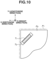
- Fig. 10 illustrates a relationship in shape and size between an adhesive toner image T 0 for bonding a front cover P 0 and a recording material P 1 , which is the first middle page, together and an adhesive toner image T 1 for bonding recording materials P 1 and P 2 , which are middle pages, together.
- the adhesive toner images T 0 and T 1 are both rectangular and are formed diagonally to the sides of the recording material in a corner of the recording material. Since the adhesive toner image T 0 is greater in area than the adhesive toner image T 1 , even in a case where the adhesive toner image T 1 is misaligned from the adhesive toner image T 0 , the appearance quality of the booklet is prevented from worsening for the same reason as in the first and second embodiments.
- a top-mounted booklet generation apparatus 301 and the thermal compression bonding unit 51 may be placed on top of the body of the image forming apparatus 1 as illustrated in Fig. 11 as a modified example.
- the embodiments disclose at least the following image forming systems.
- An image forming system including an image forming apparatus configured to form an adhesive toner image on a recording material and a booklet generation apparatus configured to generate a booklet including a recording material to be a front cover, a recording material to be a back cover, and two or more recording materials to be middle pages between the front cover and the back cover
- the booklet generation apparatus including a thermal compression bonding unit configured to heat and press an adhesive toner image portion in a state where a plurality of recording materials each with the adhesive toner image formed thereon is stacked in order to bond the plurality of recording materials together, wherein each adhesive toner image is formed so that at least one of the adhesive toner image bonding the front cover and the middle page together and the adhesive toner image bonding the back cover and the middle page together becomes greater in area than the adhesive toner image bonding the middle pages together when viewed from a direction perpendicular to a surface of the recording material, and wherein the booklet is generated so that the adhesive toner image bonding the front cover and the middle page together, the adhesive toner image bonding the
- each adhesive toner image is formed so that at least one of a shorter side of the adhesive toner image bonding the front cover and the middle page together and a shorter side of the adhesive toner image bonding the back cover and the middle page together becomes longer than a shorter side of the adhesive toner image bonding the middle pages together.
- each adhesive toner image is formed so that at least one of a longer side of the adhesive toner image bonding the front cover and the middle page together and a longer side of the adhesive toner image bonding the back cover and the middle page together becomes longer than a longer side of the adhesive toner image bonding the middle pages together.
- each adhesive toner image is formed so that at least one of a shorter side of the adhesive toner image bonding the front cover and the middle page together and a shorter side of the adhesive toner image bonding the back cover and the middle page together becomes longer than a shorter side of the adhesive toner image bonding the middle pages together.
- each adhesive toner image is formed so that at least one of a longer side of the adhesive toner image bonding the front cover and the middle page together and a longer side of the adhesive toner image bonding the back cover and the middle page together becomes longer than a longer side of the adhesive toner image bonding the middle pages together.
- the image forming system according to any one of items 1 to 9, wherein at least one of a shape or area of the adhesive toner image bonding the front cover and the middle page together and a shape or area of the adhesive toner image bonding the back cover and the middle page together is changed based on a type of the recording material.
- the image forming system according to any one of items 1 to 10, wherein at least one of a shape or area of the adhesive toner image bonding the front cover and the middle page together and a shape or area of the adhesive toner image bonding the back cover and the middle page together is changed based on an operating environment of the booklet generation apparatus.
- the image forming system according to any one of items 1 to 11, wherein the image forming apparatus is configured to form a toner image in a region other than a region where the adhesive toner image is formed on the recording material, wherein the booklet generation apparatus includes an alignment roller configured to align the plurality of recording materials, and wherein at least one of a shape or area of the adhesive toner image bonding the front cover and the middle page together and a shape or area of the adhesive toner image bonding the back cover and the middle page together is changed based on at least one of an image pattern on a portion of the toner image other than the adhesive toner image formed on the recording material and a printing rate of the portion, the portion being in contact with the alignment roller.
- the image forming system according to any one of items 1 to 12, wherein the booklet is generated so that the adhesive toner image bonding the middle pages together entirely overlaps with the adhesive toner image bonding the front cover and the middle page together when the generated booklet is viewed from a direction perpendicular to a surface of the front cover.
Landscapes
- Engineering & Computer Science (AREA)
- Physics & Mathematics (AREA)
- General Physics & Mathematics (AREA)
- Mechanical Engineering (AREA)
- Textile Engineering (AREA)
- Folding Of Thin Sheet-Like Materials, Special Discharging Devices, And Others (AREA)
- Control Or Security For Electrophotography (AREA)
Abstract
Description
- The present invention relates to an image forming system including a booklet generation apparatus that generates a booklet by applying heat and pressure to an adhesive toner formed on a plurality of recording materials and bonding the plurality of recording materials together.
- There are a booklet generation apparatus and an image forming system for forming adhesive toner images on recording materials using an electrophotographic process and bonding the recording materials together to generate a booklet as discussed in
Japanese Patent Application Laid-Open No. 2010-111025 - However, the image forming apparatus including the booklet generation apparatus as discussed in
Japanese Patent Application Laid-Open No. 2010-111025 - For example, there may be a case where recording materials set in a sheet feed cassette by a user are not regulated properly in a width direction depending on the force applied by the user and each recording material is fed and conveyed in a state of being misaligned in the width direction. Further, the recording materials may be misaligned due to various causes during bonding. In a case where such issues occur, a booklet may be generated with an adhesive toner image formed at a misaligned position on each recording material.
- In a case where a booklet is generated with an adhesive toner image formed at a misaligned position on each recording material, when the generated booklet is viewed from a front or back cover, the adhesive toner image for bonding inner recording materials of the booklet may become transparently visible outside the adhesive toner image bonding the front or back cover, which worsens the appearance and quality of the booklet.
- The present invention is directed to preventing the appearance and quality of a booklet from worsening even in a case where an adhesive toner image is formed at a misaligned position on each recording material.
- According to a first aspect of the present invention, there is provided an image forming system as specified in
claims 1 to 13. - Further features of the present invention will become apparent from the following description of embodiments with reference to the attached drawings. Each of the embodiments of the present invention described below can be implemented solely or as a combination of a plurality of the embodiments or features thereof where necessary or where the combination of elements or features from individual embodiments in a single embodiment is beneficial.
-
-
Fig. 1 is a cross-sectional view illustrating an image forming apparatus and a booklet generation apparatus according to a first embodiment. -
Figs. 2A to 2B are diagrams illustrating positions of adhesive toner images on recording materials according to the first embodiment. -
Figs. 3A to 3D are diagrams illustrating a recording material alignment method of the booklet generation apparatus according to the first embodiment. -
Fig. 4 is a cross-sectional view illustrating a thermal compression bonding unit of the booklet generation apparatus according to the first embodiment. -
Figs. 5A to 5C are diagrams illustrating an adhesive toner image pattern of a long-side bound booklet according to a comparative example. -
Figs. 6A to 6C are diagrams illustrating an adhesive toner image pattern according to the first embodiment. -
Figs. 7A to 7C are diagrams illustrating an adhesive toner image pattern of a corner bound booklet according to a comparative example. -
Figs. 8A to 8C are diagrams illustrating an adhesive toner image pattern according to a second embodiment. -
Figs. 9A to 9D are diagrams illustrating adhesive toner images according to a modified example of the second embodiment. -
Fig. 10 is a diagram illustrating an adhesive toner image pattern according to a third embodiment. -
Fig. 11 is a cross-sectional view illustrating an image forming apparatus and a booklet generation apparatus according to a modified example of the present invention. - A first embodiment of the present invention will be described below with reference to the drawings. The following embodiment is not intended to limit the present invention and may be replaced with another configuration within the spirit of the present invention. An image forming apparatus and a booklet generation apparatus according to the present embodiment will be described below with reference to
Fig. 1. Fig. 1 is a schematic diagram illustrating a cross section of animage forming apparatus 1 and abooklet generation apparatus 300 according to the first embodiment. Theimage forming apparatus 1 and thebooklet generation apparatus 300 together form animage forming system 100. Theimage forming system 100 may include a configuration in which a booklet generation function is partially or entirely embedded in theimage forming apparatus 1. - First, the
image forming apparatus 1 will be described in detail below. As illustrated inFig. 1 , theimage forming apparatus 1 includes arecording material cassette 8, atop sensor 4, animage forming unit 1e, afixing device 6, and ahousing 19. Therecording material cassette 8 stores recording materials. Thetop sensor 4 is a unit that detects leading edges of recording materials. Theimage forming unit 1e is an image forming unit. Thefixing device 6 is a fixing unit. Thehousing 19 encloses therecording material cassette 8, thetop sensor 4, theimage forming unit 1e, and thefixing device 6. Theimage forming apparatus 1 has a printing function to generate a printed material by forming a toner image on a recording material P fed from therecording material cassette 8 using theimage forming unit 1e and fixing the toner image to the recording material P using thefixing device 6. - According to the present embodiment, a maximum size at which an image can be formed on a recording material P is A4 size (length 297 mm × width 210 mm), and image forming is performed by conveying an A4-sized recording material P in a lengthwise direction.
- The
recording material cassette 8 is inserted in a lower portion of theimage forming apparatus 1 so that therecording material cassette 8 can be pulled out of thehousing 19, and a plurality of recording materials P is stored in therecording material cassette 8. Therecording material cassette 8 includes a regulating plate (not illustrated), and the regulating plate regulates a recording material width direction (a direction perpendicular to a conveyance direction on a recording material surface) that can be operated by a user. A recording material P stored in therecording material cassette 8 is fed from therecording material cassette 8 by asheet feed roller 8a, which is a sheet feed portion, and conveyed by a pair ofconveyance rollers 8b. Further, recording materials set on a multi-tray 20 may be fed singly. Thetop sensor 4 includes a flag for detecting leading edges of recording materials, and a toner image forming start position where theimage forming unit 1e starts forming a toner image is corrected based on the detection results of the flag. - The
image forming unit 1e is a tandem type electrophotographic unit including fourprocess cartridges scanner unit 2, and atransfer unit 3. A process cartridge refers to a replaceable integrated unit containing a plurality of components for an image forming process. Theprocess cartridges process cartridges - The
scanner unit 2 is situated under theprocess cartridges recording material cassette 8. Thescanner unit 2 is an exposure unit according to the present embodiment that irradiates the photosensitive drums Dk, Dy, Dm, and Dc of theprocess cartridges - The
transfer unit 3 includes atransfer belt 3a as an intermediate transfer member (secondary image bearing member). Thetransfer belt 3a is a belt member stretched around an innersecondary transfer roller 3b and atension roller 3c, and an outer peripheral surface of thetransfer belt 3a faces the photosensitive drums Dk, Dy, Dm, and Dc of theprocess cartridges transfer belt 3a, primary transfer rollers Fk, Fy, Fm, and Fc are situated at positions corresponding to the photosensitive drums Dk, Dy, Dm, and Dc. Further, asecondary transfer roller 5 as a transfer unit is situated at a position facing the innersecondary transfer roller 3b. A transfer nip 5n between thesecondary transfer roller 5 and thetransfer belt 3a is a transfer portion (secondary transfer portion) where toner images are transferred from thetransfer belt 3a onto a recording material P. - The fixing
device 6 is a fixing unit for heating the toner images on the recording material P, melting the toner images, and fixing the toner images and is situated above thesecondary transfer roller 5. The fixingdevice 6 is a fixing device that uses a heat fixing method and includes aheating film 6b and apressing roller 6c. Theheating film 6b is a fixing member that heats using aceramic heater 6a as a heat source, and thepressing roller 6c is a pressing member. Theheating film 6b may heat using a halogen lamp or a heat generation mechanism using an induction heating method. Thepressing roller 6c is rotated by a drive unit (not illustrated) and is pressed against theheating film 6b by a biasing member such as a spring to generate a pressing force to press the recording material P conveyed through a nip portion (fixingnip 6n) between theheating film 6b and thepressing roller 6c. The power input to theceramic heater 6a is controlled by a control unit so that the surface temperature of theheating film 6b becomes a predetermined value using a radiation thermometer (not illustrated). - According to the present embodiment, conventional publicly-known toners for printing may be used. Among such toners, toners for printing that use a thermoplastic resin as a binder resin are desirable. Resins that can be used in the thermoplastic resin are not particularly limited, and resins that are used in conventional toners for printing may be used, such as polyester resin, vinyl resin, acrylic resin, or styrene-acrylic resin. More than one of the resins described above may be contained. Among the resins, toners for printing that use styrene-acrylic resin are more desirable. The toners for printing may contain colorants, magnetic materials, charge control agents, waxes, and/or external additives.
- In a case where image data to be printed and an instruction to perform printing are input to the
image forming apparatus 1, a control unit (not illustrated) of theimage forming apparatus 1 starts a series of operations (image forming operation) to convey a recording material P and form an image on the recording material P. In the image forming operation, first, a recording material P is singly fed from therecording material cassette 8 and conveyed along thetop sensor 4 via the pair ofconveyance rollers 8b to the transfer nip 5n. While passing along thetop sensor 4, the recording material P pushes down the flag of thetop sensor 4 in the conveyance direction, and based on this, the control unit detects whether the leading edge of the recording material P has passed, and an image forming start position is determined based on the detection results. - Simultaneously with the feeding of the recording material P, the
process cartridges scanner unit 2 irradiates the photosensitive drums Dk, Dy, Dm, and Dc of theprocess cartridges process cartridges - The
transfer belt 3a rotates anti-clockwise (arrow v) inFig. 1 . Toner images formed by theprocess cartridges transfer belt 3a by an electric field formed between the photosensitive drums Dk, Dy, Dm, and Dc and the primary transfer rollers Fk, Fy, Fm, and Fc. - After arriving at the transfer nip 5n, the toner images borne on the
transfer belt 3a are secondarily transferred onto the conveyed recording material P by an electric field formed between thesecondary transfer roller 5 and the innersecondary transfer roller 3b. Hereinafter, the toner Tk is used to bond recording materials together, and an image after the secondary transfer of the toner Tk to the recording material P will be referred to as "adhesive toner image Ta". The present embodiment is not limited to that described above, and the adhesive toner image Ta may be formed using the toner Ty, Tm, or Tc other than the toner Tk or may be formed by overlaying several of the toners Tk, Ty, Tm, and Tc. - Thereafter, the recording material P is conveyed to the
fixing device 6 and undergoes a fixing process. Specifically, while the recording material P passes through the fixingnip 6n, the toner images on the recording material P are heated and pressed to cause the toners Ty, Tm, and Tc for printing and the adhesive toner image Ta to melt and thereafter solidify, whereby an image fixed to the recording material P is obtained.Figs. 2A and 2B illustrate predetermined image regions of the adhesive toner image Ta according to the present embodiment. As illustrated inFig. 2A , by forming the adhesive toner image Ta (hatched portion) in a lengthwise edge portion of the recording material P, a long-edge bound booklet is generated as an output of the booklet generation by thebooklet generation apparatus 300. The adhesive toner image Ta herein has a width W of 4.0 mm. Further, as illustrated inFig. 2B , by forming the adhesive toner image Ta in a corner portion formed by longer and shorter sides of the recording material P, a corner bound booklet is generated as an output. A form of generating a long-edge bound booklet according to the first embodiment will be described below. - A switching
guide 33 is a flap-shaped guide member for switching the conveyance direction based on a selected mode in a case where one of a one-sided printing mode in which an image is formed on one side of a recording material P and a two-sided printing mode in which an image is formed on both sides of a recording material P is selected. In the case of the one-sided printing mode, the switchingguide 33 conveys the recording material P to a pair ofdischarge rollers 34. - On the other hand, in the case of the two-sided printing mode, the switching
guide 33 conveys the recording material P to a pair ofswitchback rollers 35, and after the trailing edge of the recording material P is discharged, the rotation direction of the pair ofswitchback rollers 35 is reversed to convey the recording material P to a two-sided conveyance path 36 for two-sided printing. The recording material P conveyed to the two-sided conveyance path 36 passes through the secondary transfer portion and the fixing unit again so that an image is formed on an unprinted surface of the recording material P, and the switchingguide 33 eventually conveys the recording material P to the pair ofdischarge rollers 34. The image forming operation of theimage forming apparatus 1 has been described above. Operations after the conveyance to the pair ofdischarge rollers 34 will be described below as an operation of thebooklet generation apparatus 300. Further, anoperation panel 50 is on the outside of thehousing 19 and includes a liquidcrystal display unit 50a, and the user can view the liquidcrystal display unit 50a and perform touch operations on the liquidcrystal display unit 50a. An operating status of theimage forming apparatus 1 and a status of consumables such as toners are displayed on the liquidcrystal display unit 50a of theoperation panel 50 by the control unit, and the liquidcrystal display unit 50a has a navigation function to guide the user through specific operations. - A cross section of the
booklet generation apparatus 300 according to the first embodiment and a booklet generation operation to generate a booklet will be described below with reference toFig. 1 . The recording material P having undergone the image forming by theimage forming apparatus 1 is conveyed to thebooklet generation apparatus 300 via anintermediate conveyance unit 200 including pairs ofconveyance rollers booklet generation apparatus 300 is a floor standing type and includes a recording material alignment unit and a thermalcompression bonding unit 51 in its lower portion. The thermalcompression bonding unit 51 is a heating and pressing unit that heats and presses a bundle of aligned recording materials for a predetermined time. - The recording material P conveyed from the
intermediate conveyance unit 200 is passed to a pair ofconveyance rollers 21 of thebooklet generation apparatus 300. Based on a time at which the trailing edge passes through anentrance sensor 27, a pair ofconveyance rollers 22 accelerates the recording material P at a predetermined timing. In a case where the recording material P is to be discharged to anupper discharge tray 25, once the trailing edge of the recording material P reaches between the pair ofconveyance rollers 22 and reverserollers 24, the recording material P is decelerated to a predetermined discharge speed and is discharged to theupper discharge tray 25. During the booklet generation process by the thermalcompression bonding unit 51, an output destination of the recording material P is alower discharge tray 37. In this case, anon-return valve 23 biased clockwise by a spring (not illustrated) temporarily stops conveying the recording material P at the timing when the trailing edge of the recording material P exits, and thereafter thenon-return valve 23 switches the recording material P back and conveys the recording material P toinner discharge rollers 26. The recording material P conveyed from theinner discharge rollers 26 is conveyed to kick-outrollers 29 viaintermediate conveyance rollers 28 and conveyed to an intermediate stackingunit 42. At the bottommost part of the intermediate stackingunit 42, lengthwisealignment reference plates 39 are placed, and the bundle of recording materials P is aligned by pressing end portions of the recording materials P in the conveyance direction against the lengthwisealignment reference plates 39. - A method of aligning the recording materials P will be described below with reference to
Figs. 3A to 3D . Widthwise, lengthwise, and height directions of the recording materials P will be referred to X, Y, and Z directions, respectively. InFig. 3A , a semicircular roller (alignment roller) 32 for pushing the recording materials P exited from the kick-outrollers 29 against the lengthwisealignment reference plates 39 is supported to rotate freely in the intermediate stackingunit 42. Thesemicircular roller 32 conveys the recording materials P to the lengthwisealignment reference plates 39 at a predetermined timing. InFig. 3B , a conveyance pressure of thesemicircular roller 32 is controlled to a particular pressure so that after the recording materials P are pressed against the lengthwisealignment reference plates 39, thesemicircular roller 32 slips on the recording material P. Further, abundle pressing flag 30 for preventing the trailing edge of the recording material P from lifting as illustrated inFig. 1 is supported downstream of the kick-outrollers 29 to rotate freely so that the trailing edge of the recording material P stacked in the intermediate stackingunit 42 and the leading edge of the subsequent recording material P do not interfere with each other. After the recording materials P reach the lengthwisealignment reference plates 39, an alignment operation is performed until awidthwise alignment jogger 41a is pressed against a widthwise alignment reference plate 500 (dashed line) as illustrated inFig. 3C , and the bundle of recording materials P is aligned at a predetermined position as illustrated in inFig. 3D . After the alignment of a predetermined number of recording materials P ends, the thermalcompression bonding unit 51 as a recording material bonding unit performs a heating and pressing process. The thermalcompression bonding unit 51 performs the heating and pressing process on the plurality of recording materials P to generate a bundle of recording materials P. The thermalcompression bonding unit 51 performs the heating and pressing process on the bundle of recording materials P aligned in the lengthwise and widthwise directions to thereby generate a bundle of recording materials P (booklet). - The structure of the thermal
compression bonding unit 51 will be described further below with reference toFig. 4. Fig. 4 is a cross-sectional view illustrating the thermalcompression bonding unit 51. The thermalcompression bonding unit 51 places aheating plate 502 in contact with a surface of aceramic heater 501. Theheating plate 502 is made of aluminum and has a thickness of 1.5 mm, and theceramic heater 501 includes a heat generation member as a heating source and has a thickness of 1.0 mm. The temperature of theceramic heater 501 is controlled to a target temperature of 240°C constantly by a temperature detection unit (not illustrated) and a power application unit (not illustrated) supported by aheater support member 503, whereby the surface temperature of theheating plate 502 is controlled to 200°C. Further, theceramic heater 501 is supported by theheater support member 503 made of resin. Apressing lever 504 obtains power from a drive source (not illustrated) to press the thermalcompression bonding unit 51 in the Z direction (downward direction) to apply pressure to the bundle of recording materials P. The pressure from thepressing lever 504 is transmitted to the bundle of recording materials P, for example, at an average surface pressure of 0.2 MPa via ametal stay 505. A pressure range on the bundle of recording materials P is 8.0 mm in the X direction (widthwise direction) and 300 mm in the Y direction (lengthwise direction), and the pressure center is a position of a midpoint of the pressure range in the widthwise direction. A receivingmember 506 is a silicone rubber plate with a thickness of 2.0 mm and is a member for stably withstanding the pressure. Further, the pressure applied to the bundle of recording materials P is controlled by controlling a pressing amount of thepressing lever 504. Then, the thermalcompression bonding unit 51 presses the bundle of recording materials P for, for example, 2.0 seconds and thereafter separates. - By the foregoing process, the adhesive toner image Ta applied to the recording material P acts as an adhesive through heat melting and solidification to bond the recording materials P together. Further, according to the present embodiment, the adhesive toner image Ta is applied to the recording material P in an amount of about 0.5 mg/cm2, and the adhesive toner image Ta with a specific gravity of about 1.0 g/cm3 is used.
- The
booklet generation apparatus 300 according to the present embodiment generates a booklet by repeating a process of stacking a plurality of recording materials P, performing the heating and pressing process on the stacked recording materials P, stacking a plurality of recording materials P on the bundle of recording materials P having undergone the heating and pressing process, and performing the heating and pressing process. For example, in a case where five recording materials P are stacked at a time, in order to generate a booklet of 15 recording materials P, the process described above is performed three times in total. - After the binding process of the thermal
compression bonding unit 51 is complete, a bundle discharge guide (not illustrated) moves parallel from a stand-by position toward a recordingmaterial discharge port 45 to thereby push out the bundle of recording materials P. The recordingmaterial discharge port 45 is provided withbundle discharge rollers 38. Once the leading edges of the bundle of recording materials P reach a position slightly beyond thebundle discharge rollers 38, the bundle discharge guide stops and returns to the stand-by position. Thebundle discharge rollers 38 discharge the bundle of recording materials P received from the bundle discharge guide to thelower discharge tray 37. - In relation to factors that may worsen the appearance of a booklet, which is the issue of the present application, an example of a mechanism causing misalignment of adhesive toner images formed on recording materials of a booklet will be described below. A case where an adhesive toner image is formed at a position misaligned from a predetermined position on a recording material by the image forming operation as illustrated in
Fig. 2A will be described below. The width of the regulating plate of therecording material cassette 8 in the width direction of the recording materials can be changed manually by the user, and there is a suitable regulation position for the size of the recording materials. However, there may be a case where the regulation on the width direction of the recording materials loosens because, for example, the user incorrectly sets the regulating plate at an unsuitable position for the size of recording materials stacked in therecording material cassette 8 or the regulating plate becomes unstable due to manufacturing tolerances. In a case where a recording material is fed from therecording material cassette 8 in the state where the regulation is loose, the recording material may be skewed and conveyed in the skewed state to the image forming portion. In a case where the image forming operation is performed while the recording material remains skewed, an adhesive toner image is formed at a position misaligned from the predetermined position as illustrated inFig. 2A , and "misalignment of adhesive toner images" occurs. - Further, misalignment of adhesive toner images may occur even in generating, for example, a booklet of a combination of thick paper and thin paper using the multi-tray 20 and the
recording material cassette 8. For example, in a case where the recording materials differ in thickness from each other, a small deviation may occur in the timing of pushing down the flag of thetop sensor 4. Thus, the image forming start position varies between thick paper and thin paper, and misalignment of adhesive toner images may occur with respect to the conveyance direction in generating a booklet of a combination of thick paper and thin paper. In a case where there is a change in the type of some of the recording materials in the booklet, the user is to input information indicating that a booklet is to be generated using the changed type of recording materials only for front and back covers to thebooklet generation apparatus 300, or the type of the recording materials may be identified using a sensor to address the change. Further, it is assumed that one type of recording materials is used in one booklet, and even in a case where different types of recording materials are used for different booklets, the possibility that the deviation in the timing to push down the flag of thetop sensor 4 varies for each booklet may be taken into consideration. As described above, in a case where an adhesive toner image is formed at a position misaligned from the predetermined position on a recording material, the adhesive toner images formed on the recording materials of a booklet generated in thebooklet generation apparatus 300 become misaligned. When the booklet in which the adhesive toner images on the recording materials are misaligned is viewed from its front cover, the misaligned adhesive toner images inside the booklet are transparently visible from the front cover, which may worsen the appearance of the booklet. Especially in a case where the toners used to form the adhesive toner images Ta include a color toner, the adhesive toner images Ta are often transparently visible and easily recognizable, which often has a negative impact on the booklet quality. - Next, a method for forming an adhesive toner image (image pattern) that is a feature of the present embodiment will be described below with reference to
Figs. 5A to 5C and6 . According to the present embodiment, an adhesive toner image has a rectangular shape and is formed so that the longer side of the rectangular shape is aligned with the longer side of the recording material as illustrated inFigs. 5A to 5C and6 . - Alternatively, the rectangular shape may be formed so that the longer side of the rectangular shape is aligned with the shorter side of the recording material.
Figs. 5A to 5C illustrate, as a comparative example of the present embodiment, a case where adhesive toner images formed on recording materials have the same size and a booklet is generated with the adhesive toner images misaligned on the recording materials conveyed in a skewed state to the image forming portion. - In
Figs. 5A to 5C , widthwise, lengthwise, and heigh directions of the booklet will be referred to as X, Y, and Z directions, respectively. A front cover P0 is a front cover of the booklet, a recording material P1 is the first recording material from the front cover of the booklet toward the inside (-Z direction), and a recording material P2 is the next recording material toward the inside of the booklet. Further, a back cover Pj is a back cover of the booklet. The recording materials P1 to Pj-1 are recording materials sandwiched between the front and back covers of the booklet and will therefore be referred to as middle pages, and according to the present embodiment, there are two or more middle pages. An adhesive toner image T0 is an adhesive toner image for bonding the recording material P0, which is the front cover, and the recording material P1, which is a middle page, together, and an adhesive toner image T1 is an adhesive toner image for bonding the recording materials P1 and P2 together. Further, an adhesive toner image Tj-1 is an adhesive toner image for bonding the back cover of the booklet. In the comparative example illustrated inFigs. 5A to 5C , all the adhesive toner images including the adhesive toner images T0 and T1 formed on the recording materials have the same size with a width (X direction) of 4 mm and a length (Y direction) of 287 mm.Figs. 5A to 5C illustrate a case where the recording material P1 is skewed and only the adhesive toner image T1 formed on the recording material P1 is misaligned, and inFigs. 5A to 5C , the adhesive toner image T1 is misaligned from the predetermined position by a maximum of 2 mm in the widthwise direction (X direction) and a maximum of 2 mm in the lengthwise direction (Y direction).Fig. 5A is a diagram illustrating the generated booklet viewed from the front cover (Z direction).Fig. 5B is a diagram illustrating the booklet viewed from the bottom of the booklet (α direction inFig. 5A). Fig. 5C is a diagram illustrating the booklet viewed from the spine of the booklet (β direction inFig. 5A ). As illustrated inFig. 5A , there is a misalignment of the adhesive toner image T0 for bonding the recording materials P0 and P1 together and the adhesive toner image T1 for bonding the recording materials P1 and P2 together in the booklet from the recording material P0, which is the front cover, to the recording material Pj, which is the back cover, generated by thebooklet generation apparatus 300. As to specific misalignment directions, as illustrated inFig. 5B , the adhesive toner image T1 is misaligned from the adhesive toner images T0 and Tj-1 in the widthwise direction (-X direction). Further, as illustrated inFig. 5C , the adhesive toner image T1 is misaligned from the adhesive toner images T0 and Tj-1 also in the lengthwise direction (Y direction). Consequently, the adhesive toner image T1 becomes transparently visible when the adhesive toner image portion is viewed from the front cover of the booklet, which worsens the appearance of the booklet. As described above, in a case where all the adhesive toner images including the adhesive toner images T0 and T1 formed on the recording materials have the same size, an occurrence of a misalignment of the adhesive toner images due to skewing worsens the appearance of the booklet. - Next, an adhesive toner image pattern according to the present embodiment that does not cause the appearance of the booklet to worsen even in a case where there is a misalignment of adhesive toner images will be described below with reference to
Figs. 6A to 6C . InFigs. 6A to 6C , widthwise, lengthwise, and height directions of the booklet will be referred to as X, Y, and Z directions, respectively. A front cover P0 is a front cover of the booklet, a recording material P1 is the first recording material from the front cover of the booklet toward the inside (-Z direction), and a recording material P2 is the next recording material toward the inside of the booklet. Further, a back cover Pj is a back cover of the booklet. An adhesive toner image T0' is an adhesive toner image for bonding the recording material P0, which is the front cover, and the recording material P1, which is a middle page, together, and an adhesive toner image T1 is an adhesive toner image for bonding the recording materials P1 and P2 together. Further, an adhesive toner image Tj-1 is an adhesive toner image for bonding the back cover of the booklet.Figs. 6A to 6C illustrate a case where the recording material P1 is skewed and only the adhesive toner image T1 formed on the recording material P1 is misaligned as in the comparative example illustrated inFigs. 5A to 5C . - In
Figs. 6A to 6C , the adhesive toner image T1 is also misaligned from the predetermined position by a maximum of 2 mm in the widthwise direction (X direction) and a maximum of 2 mm in the lengthwise direction (Y direction).Fig. 6A is a diagram illustrating the generated booklet viewed from the front cover (Z direction).Fig. 6B is a diagram illustrating the booklet viewed from the bottom of the booklet (α direction inFig. 6A). Fig. 6C is a diagram illustrating the booklet viewed from the spine of the booklet (β direction inFig. 6A ). - A feature of the present embodiment is that even in a case where there is a misalignment of the adhesive toner images, in order to maintain the appearance of the booklet, the adhesive toner image T0' for bonding the front cover and the middle page together is formed to be greater in size than the adhesive toner images (T1 to Tj-1) for bonding the middle pages together. The adhesive toner image T0' according to the present embodiment has a width (X direction) of 6 mm and a length (Y direction) of 289 mm. The width and the length are greater than the width (X direction), which is 4 mm, and the length (Y direction), which is 287 mm, of the adhesive toner images (T1 to Tj-1) formed on the recording materials other than the front cover of the booklet. Specifically, the adhesive toner image T0' is greater in area than the adhesive toner images (T1 to Tj-1) when viewed from the direction perpendicular to the surfaces of the recording materials.
- A relationship in the widthwise direction (X direction), the lengthwise direction (Y direction), and the height direction (Z direction) of the adhesive toner image regions formed on the recording materials of the booklet will be described below. As illustrated in
Fig. 6B , the adhesive toner image T0' is formed to be longer in the widthwise direction (-X direction) than the adhesive toner images (T1 to Tj-1). Further, as illustrated inFig. 6C , the adhesive toner image T0' is formed to be longer in the lengthwise direction (Y direction) than the adhesive toner images (T1 to Tj-1). Consequently, as illustrated inFig. 6A , the adhesive toner image T1 is not transparently visible although the adhesive toner images on the recording materials for bonding the middle pages together are misaligned when viewed from the front cover. The adhesive toner image for bonding the front cover and the middle page together is formed to be greater in area than the adhesive toner images for bonding the middle pages together so that even in a case where an adhesive toner image formed in the booklet is misaligned from the adhesive toner image on the front cover, the misaligned adhesive toner image is not transparently visible from the front cover, which prevents the appearance of the booklet from worsening. This is because the booklet is generated so that the adhesive toner image portions for bonding the middle pages together are entirely covered by the adhesive toner image for bonding the front cover and the middle page together when the booklet is viewed from the front cover. - Desirably, the size of the adhesive toner image T0' for bonding the front cover is determined considering a maximum value of an amount of misalignment of images that may occurs in the
image forming apparatus 1. Specifically, the adhesive toner image T0' is desirably large enough to cover even the maximum misalignment of images. However, from the point of view of the adhesive toner consumption, the adhesive toner image T0' is desirably set to the smallest possible area that still covers the entire region where misalignment of adhesive toner images may occur. Not only the area of the adhesive toner image for bonding the front cover and the middle page together but also the area of the adhesive toner image for bonding the back cover and the middle page together may be increased, or both the area of the adhesive toner image for bonding the front cover and the middle page together and the area of the adhesive toner image for bonding the back cover and the middle page together may be increased. - While the adhesive toner image on the front cover of the booklet is increased in length in both the lengthwise and widthwise directions of the booklet according to the present embodiment, the image may be enlarged only in the lengthwise direction of the booklet or only in the widthwise direction of the booklet. For example, in a case where there is a tendency for the recording materials to become skewed in a particular direction, a misalignment of the adhesive toner images is likely to occur in the skew direction, so that it is desirable to select a direction for increasing the length of the adhesive toner images based on the tendency. Further, in a case where recording materials having a different thickness from each other are used to generate a booklet, the timing to push down the flag of the
top sensor 4 may vary slightly due to the difference in thickness between the recording materials, and this changes the image forming start position of the adhesive toner images in the lengthwise direction, so that only the length in the lengthwise direction of the recording materials may be increased. Thus, even in a case where the adhesive toner images for bonding the middle pages together are misaligned in both the lengthwise direction and the widthwise direction from the adhesive toner image for bonding the front cover and the middle page together, the adhesive toner images are prevented from becoming transparently visible by increasing only in the lengthwise direction or only in the widthwise direction, so that the appearance is expected to improve. - There are other possible mechanisms causing misalignment of adhesive toner images besides the above-described mechanism according to the present embodiment. For example, the
booklet generation apparatus 300 may fail to align recording materials properly in generating a booklet. In thebooklet generation apparatus 300 illustrated inFigs. 3A to 3D , thewidthwise alignment jogger 41a presses the recording materials against the widthwisealignment reference plate 500 for the alignment in the X direction (widthwise direction), so that the recording materials are less likely to be misaligned in the X direction. On the other hand, the alignment of the recording materials in the Y direction (lengthwise direction) is performed by pressing the recording materials against the lengthwisealignment reference plates 39 using thesemicircular roller 32. The frictional force between thesemicircular roller 32 and a recording material varies depending on a toner image pattern formed on a portion of the recording material that is in contact with thesemicircular roller 32 and pressed by thesemicircular roller 32 and a printing rate of the portion. Thus, the pressing force from the recording material against lengthwisealignment reference plates 39 also varies, and this may make it difficult for the recording material to be aligned with the lengthwisealignment reference plates 39. In a case where the recording materials undergoes the binding process of the thermalcompression bonding unit 51 without being properly aligned, the adhesive toner images on the recording materials of the booklet may be misaligned, and the adhesive toner images for bonding the middle pages together may become visible, which worsens the appearance. - In this case, it is desirable to increase the length of the adhesive toner images only in the direction that is aligned with the
semicircular roller 32. As described above, it is desirable to select a direction for increasing the length of the adhesive toner image T0' on the front cover of the booklet based on the toner image pattern formed on the recording material and the printing rate. Specifically, it is desirable to change the shape and/or size of the adhesive toner images. - The extent of skew of recording materials in the
image forming apparatus 1 and the extent of misalignment of recording materials in thebooklet generation apparatus 300 as described above vary depending on physical property values of the recording materials, such as thickness, surface properties, and moisture content (paper stiffness). Specifically, the direction in which a misalignment of adhesive toner images occurs and the misalignment amount vary depending on the types of recording materials used to generate a booklet and an operating environment (such as temperature and humidity). Examples regarding the thickness and surface properties are as described above. Regarding the moisture content, for example, thin paper and plain paper with high moisture content are easily curled in the width direction, and this often makes the alignment in the widthwise direction difficult, so that it is desirable to increase the length of the adhesive toner image T0' in the width direction. To measure the operating environment (such as temperature and humidity) of thebooklet generation apparatus 300, sensors for the measurement are installed in thebooklet generation apparatus 300 or in theimage forming apparatus 1 connected to thebooklet generation apparatus 300. Desirably, directions in which misalignment of adhesive toner images tends to occur and misalignment amounts are identified in advance for each type of recording materials and for each operating environment of thebooklet generation apparatus 300, and the shape and size of the adhesive toner image T0' on the front cover of the booklet are changed based on booklet generation conditions (types of recording materials, operating environment). Specifically, the adhesive toner image T0' on the front cover is set to the smallest possible area that still covers the entire region where misalignment of adhesive toner images may occur for each booklet generation condition (types of recording materials, operating environment). For example, in a booklet generation condition in which misalignment of adhesive toner images is small, the adhesive toner image T0' on the front cover may be set to be smaller than the region (6 mm × 289 mm) according to the present embodiment described above. By changing the shape and size of the adhesive toner image T0' on the front cover of the booklet for each booklet generation condition (types of recording materials, operating environment) so that the adhesive toner image T0' is set to a minimum required area for the booklet generation condition, the appearance of the booklet is prevented from worsening while reducing the adhesive toner consumption. - Next, evaluation experiments conducted to check effects of the present embodiment will be described below. Effects of increasing the area of an adhesive toner image for bonding a front cover of a booklet to be greater than the area of adhesive toner images for bonding middle pages together will be evaluated. In the evaluation experiments, the present embodiment in which the area of the adhesive toner image T0' for bonding the front cover is increased as illustrated in
Fig. 6A and the comparative example in which all the adhesive toner images formed on the recording materials have the same area as illustrated inFig. 5A are compared. In each ofFigs. 5A to 5C and6A to 6C , the adhesive toner image T1 is misaligned from the predetermined position by a maximum of 2 mm in the widthwise direction (-X direction) and a maximum of 2 mm in the lengthwise direction (Y direction). - In the evaluation experiments on the present embodiment, a booklet was generated using a CS-060F (manufactured by Canon) as recording materials, and misalignment of adhesive toner images transparently visible from a front cover was evaluated by measuring densities of toners transparently visible from the front cover. As to evaluation conditions, a booklet of the comparative example was placed on 10 sheets of GFC081 (manufactured by Canon) placed on top of another on a horizontal flat surface, and a booklet of the present embodiment was placed on other 10 sheets of GFC081 (manufactured by Canon) placed on top of another on a horizontal flat surface. Then, densities of adhesive toner images at image edge portions and densities of backgrounds of the recording materials were measured from the front covers (-Z direction) of the booklets using a digital microscope (PIAS®-II manufactured by QEA). The 10 sheets of GFC081 (manufactured by Canon) were placed on top of another to eliminate the influence of densities of backgrounds other than the measurement samples. In the evaluation experiments, standard set conditions for wavelength range in density are a status T.
- The image edge portion according to the present embodiment refers to a position misaligned by 1 mm in the widthwise direction (-X direction) from an edge of the adhesive toner image T0 bonding the front cover of the booklet as illustrated in
Fig. 5A . The background portion according to the present embodiment refers to a region without an adhesive toner image or a toner image for printing, such as a margin portion, as illustrated inFig. 5A . The image edge portion and the background portion inFig. 6A were measured under the same conditions. - Table 1 presents measurement results of densities of the image edge portions and the background portions of the booklets of the comparative example and the present embodiment and calculation results of differences between the densities of the image edge portions and the background portions.
Table 1 Comparison of Densities between Present Embodiment and Comparative Example Comparative Example Present Embodiment Density of Image Edge Portion 0.14 0.07 Density of Background Portion 0.07 0.07 Difference in Density 0.07 0.00 - As described above, in the comparative example in which all the adhesive toner images formed on the recording materials have the same size, the density of the image edge portion is 0.14, and the density of the background is 0.07. Therefore, the difference in density between the adhesive toner image edge portion and the background is 0.07. The presence of the difference in density indicates that an adhesive toner image bonding middle pages together is transparently visible, and the adhesive toner image T1 of the booklet of the comparative example is transparently visible when viewed from the front cover, which worsens the appearance of the booklet.
- On the other hand, in the present embodiment in which the area of the adhesive toner image T0' bonding the front cover is increased, the density of the image edge portion is 0.07, and the density of the background is 0.07. Therefore, the difference in density between the adhesive toner image edge portion and the background is 0.00. The absence of the difference in density indicates that the adhesive toner images bonding the middle pages together are not transparently visible.
- As described above, according to the present embodiment, the area of the adhesive toner image for bonding the front cover of the booklet is increased so that even in a case where misalignment of the adhesive toner images occurs, the adhesive toner images bonding the middle pages together are not visible from the front cover, which prevents the appearance of the booklet from worsening. In a case where the number of recording materials in the booklet increases or the recording materials increase in thickness or white level, misalignment of the adhesive toner images in the booklet becomes less visible.
- Since the feature of the present embodiment is that misalignment of adhesive toner images is prevented from becoming transparently visible from the front cover, the adhesive toner image for bonding the front cover is to have the greatest size among the adhesive toner images in a visible range (on the visible recording materials). Thus, patterns and sizes of adhesive toner images in the booklet that are outside the visible range from the front or back cover are not particularly limited. The visible range herein refers to, for example, a case where the difference in density is 0.01 or higher in a case where there is a misalignment of adhesive toner images. Specifically, in a case where the recording materials are thick or high in white level, the visible range often becomes small (the number of visible recording materials decreases).
- Further, as another effect, if the area of the adhesive toner for bonding the front cover and the middle page together is increased, the adhesive toner is present also in portions near edges of end portions of longer and shorter sides of the recording materials, which prevents the end portions of the longer and shorter sides of the front cover from lifting. Similar effects are also produced with respect to the back cover.
- Next, a second embodiment of the present invention will be described below. Descriptions of those that are similar to the first embodiment will be omitted below. The second embodiment is intended to generate a corner bound booklet, and a form with adhesive toner image shapes different from those according to the first embodiment will be described below. An adhesive toner image forming method (image pattern) that is a feature of the present embodiment will be described below with reference to
Figs. 7A to 7C and8A to 8C . According to the present embodiment, as illustrated inFigs. 7A to 7C and8A to 8C , adhesive toner images are triangular-shaped and formed in corner portions formed by the longer and shorter sides of the recording materials. -
Figs. 7A to 7C illustrate, as a comparative example, a case where a recording material is skewed and conveyed to the image forming portion and a booklet in which adhesive toner images are misaligned is generated. InFigs. 7A to 7C , widthwise, lengthwise, and height directions of the booklet will be referred to as X, Y, and Z directions, respectively. A front cover P0 is a front cover of the booklet, a recording material P1 is the first recording material from the front cover of the booklet toward the inside (-Z direction), and a recording material P2 is the next recording material toward the inside of the booklet. Further, a back cover Pj is a back cover of the booklet. An adhesive toner image T0 is an adhesive toner image for bonding the recording material P0, which is the front cover, and the recording material P1, which is a middle page, together, and an adhesive toner image T1 is an adhesive toner image for bonding the recording materials P1 and P2 together. Further, an adhesive toner image Tj-1 is an adhesive toner image for bonding the back cover of the booklet. In the comparative example illustrated inFigs. 7A to 7C , all the adhesive toner images including the adhesive toner images T0 and T1 formed on the recording materials have the same right triangular shape with a side (length 6 mm) parallel to the X direction and a side (length 12 mm) parallel to the Y direction.Figs. 7A to 7C illustrate a case where the recording material P1 is skewed and only the adhesive toner image T1 formed on the recording material P1 is misaligned, and inFigs. 7A to 7C , the adhesive toner image T1 is misaligned from the predetermined position by a maximum of 2 mm in the widthwise direction (X direction) and a maximum of 2 mm in the lengthwise direction (Y direction).Fig. 7A is a diagram illustrating the generated booklet viewed from the front cover (Z direction).Fig. 7B is a diagram illustrating the booklet viewed from the bottom of the booklet (α direction inFig. 7A). Fig. 7C is a diagram illustrating the booklet viewed from the spine of the booklet (β direction inFig. 7A ). As illustrated inFig. 7A , there is a misalignment of the adhesive toner image T0 for bonding the recording materials P0 and P1 together and the adhesive toner image T1 for bonding the recording materials P1 and P2 together in the booklet from the recording material P0, which is the front cover, to the recording material Pj, which is the back cover, generated by thebooklet generation apparatus 300. As illustrated inFig. 7B , the adhesive toner image T1 is misaligned from the adhesive toner images T0 and Tj-1 in the widthwise direction (-X direction). Further, as illustrated inFig. 7C , the adhesive toner image T1 is misaligned from the adhesive toner images T0 and Tj-1 also in the lengthwise direction (Y direction). Consequently, the adhesive toner image T1 becomes transparently visible when the adhesive toner image portion is viewed from the front cover of the booklet, which worsens the appearance of the booklet. As described above, in a case where all the adhesive toner images including the adhesive toner images T0 and T1 formed on the recording materials have the same size, an occurrence of a misalignment of the adhesive toner images due to skewing worsens the appearance of the booklet. - Next, an adhesive toner image pattern according to the present embodiment that does not cause the appearance of the booklet to worsen even in a case where there is a misalignment of adhesive toner images will be described below with reference to
Figs. 8A to 8C . InFigs. 8A to 8C , widthwise, lengthwise, and height directions of the booklet will be referred to as X, Y, and Z directions, respectively. A front cover P0 is a front cover of the booklet, a recording material P1 is the first recording material from the front cover of the booklet toward the inside (-Z direction), and a recording material P2 is the next recording material toward the inside of the booklet. Further, a back cover Pj is a back cover of the booklet. An adhesive toner image T0' is an adhesive toner image for bonding the recording material P0, which is the front cover, and the recording material P1, which is a middle page, together, and an adhesive toner image T1 is an adhesive toner image for bonding the recording materials P1 and P2 together. Further, an adhesive toner image Tj-1 is an adhesive toner image for bonding the back cover of the booklet.Figs. 8A to 8C illustrate a case where the recording material P1 is skewed and only the adhesive toner image T1 formed on the recording material P1 is misaligned as in the comparative example illustrated inFigs. 7A to 7C . - In
Figs. 8A to 8C , the adhesive toner image T1 is also misaligned from the predetermined position by a maximum of 2 mm in the widthwise direction (X direction) and a maximum of 2 mm in the lengthwise direction (Y direction).Fig. 8A is a diagram illustrating the generated booklet viewed from the front cover (Z direction).Fig. 8B is a diagram illustrating the booklet viewed from the bottom of the booklet (α direction inFig. 8A). Fig. 8C is a diagram illustrating the booklet viewed from the spine of the booklet (β direction inFig. 8A ). A feature of the present embodiment is that even in a case where there is a misalignment of the adhesive toner images, in order to maintain the appearance of the booklet, the adhesive toner image T0' for bonding the front cover and the middle page together is formed to be greater in size than the adhesive toner images (T1 to Tj-1) for bonding the middle pages together. The adhesive toner image T0' according to the present embodiment is formed in the shape of a right triangle with a side (length 8 mm) parallel to the X direction and a side (length 14 mm) parallel to the Y direction. The adhesive toner images (T1 to Tj-1) formed on the recording materials that are middle pages are each in the shape of a right triangle with a side (length 6 mm) parallel to the X direction and a side (length 12 mm) parallel to the Y direction. - A relationship in the widthwise direction (X direction), the lengthwise direction (Y direction), and the height direction (Z direction) of the adhesive toner image regions formed on the recording materials of the booklet will be described below. As illustrated in
Fig. 8B , the adhesive toner image T0' is formed to be longer in the widthwise direction (-X direction) than the adhesive toner images (T1 to Tj-1). Further, as illustrated inFig. 8C , the adhesive toner image T0' is formed to be longer in the lengthwise direction (Y direction) than the adhesive toner images (T1 to Tj-1). Consequently, as illustrated inFig. 8A , the formed adhesive toner image T1 misaligned from the predetermined position is not transparently visible when viewed from the front cover. As described above, by increasing the area of the adhesive toner image for bonding the front cover of the booklet, misalignment of adhesive toner images in the booklet becomes invisible from the front cover, which prevents the appearance of the booklet from worsening. - Desirably, the size of the adhesive toner image T0' for bonding the front cover is determined considering a maximum value of an amount of misalignment of images that may occurs in the
image forming apparatus 1. Specifically, the adhesive toner image T0' is desirably large enough to cover even the maximum misalignment of images. The recording material where the area of the adhesive toner image is to be increased to be greater than the area of the adhesive toner images for bonding the middle pages together is not limited to the front cover only and may be the back cover only or may be both the front and back covers. While the adhesive toner image on the front cover of the booklet is increased in length in both the lengthwise and widthwise directions of the booklet according to the present embodiment, the image may be increased in length only in the lengthwise direction of the booklet or only in the widthwise direction of the booklet. Further, the shape and size of at least one of the adhesive toner images on the front and back covers of the booklet may be changed based on the types of the recording materials and the operating environment. Desirably, the adhesive toner image for bonding at least one of the front and back covers of the booklet is greater in area than the adhesive toner images for bonding the middle pages together among the adhesive toner images in the visible range (on the visible recording materials). - While all the adhesive toner image patterns for bonding the booklet on the recording materials have the same triangular shape according to the present embodiment, this is not a limiting shape. For example, adhesive toner image patterns illustrated in
Figs. 9A to 9D also fall under the present embodiment. An example that prevents the appearance of a booklet from worsening due to misalignment of adhesive toner images on recording materials of the booklet in a case where the adhesive toner images differ from each other will be described below with reference toFigs. 9A to 9D . As illustrated inFigs. 9A to 9D , an adhesive toner image T0 for bonding a front or back cover is greater in area than an adhesive toner image T1 for bonding middle pages. InFig. 9A , the adhesive toner image T0 is triangular, while the adhesive toner image T1 is circular. InFig. 9B , the adhesive toner image T0 is triangular, while the adhesive toner image T1 is diamond-shaped. InFig. 9C , the adhesive toner image T0 is triangular, while the adhesive toner image T1 is rectangular. InFig. 9D , the adhesive toner image T0 is triangular, while the adhesive toner image T1 is butterfly-shaped. As described above, the adhesive toner image for bonding at least one of the front and back covers of the booklet and the adhesive toner images for bonding the middle pages together may be in any shape as long as the former is greater in size than the latter. - Next, a third embodiment of the present invention will be described below. Descriptions that are similar to those of the first or second embodiment will be omitted below. The third embodiment is intended to generate a corner bound booklet, and a form with adhesive toner image shapes different from those according to the second embodiment will be described below.
-
Fig. 10 illustrates a relationship in shape and size between an adhesive toner image T0 for bonding a front cover P0 and a recording material P1, which is the first middle page, together and an adhesive toner image T1 for bonding recording materials P1 and P2, which are middle pages, together. The adhesive toner images T0 and T1 are both rectangular and are formed diagonally to the sides of the recording material in a corner of the recording material. Since the adhesive toner image T0 is greater in area than the adhesive toner image T1, even in a case where the adhesive toner image T1 is misaligned from the adhesive toner image T0, the appearance quality of the booklet is prevented from worsening for the same reason as in the first and second embodiments. - While the
booklet generation apparatus 300 including the thermalcompression bonding unit 51 is placed next to theimage forming apparatus 1 according to the first to third embodiments, a top-mountedbooklet generation apparatus 301 and the thermalcompression bonding unit 51 may be placed on top of the body of theimage forming apparatus 1 as illustrated inFig. 11 as a modified example. - The embodiments disclose at least the following image forming systems.
- An image forming system including an image forming apparatus configured to form an adhesive toner image on a recording material and a booklet generation apparatus configured to generate a booklet including a recording material to be a front cover, a recording material to be a back cover, and two or more recording materials to be middle pages between the front cover and the back cover, the booklet generation apparatus including a thermal compression bonding unit configured to heat and press an adhesive toner image portion in a state where a plurality of recording materials each with the adhesive toner image formed thereon is stacked in order to bond the plurality of recording materials together, wherein each adhesive toner image is formed so that at least one of the adhesive toner image bonding the front cover and the middle page together and the adhesive toner image bonding the back cover and the middle page together becomes greater in area than the adhesive toner image bonding the middle pages together when viewed from a direction perpendicular to a surface of the recording material, and wherein the booklet is generated so that the adhesive toner image bonding the front cover and the middle page together, the adhesive toner image bonding the back cover and the middle page together, and the adhesive toner image bonding the middle pages together overlap when viewed from the direction perpendicular to the surface of the recording material.
- The image forming system according to
item 1, wherein the adhesive toner image bonding the front cover and the middle page together and the adhesive toner image bonding the back cover and the middle page together are formed in a rectangular shape so that a longer side of the rectangular shape is aligned with a longer or shorter side of the recording material. - The image forming system according to
item 2, wherein each adhesive toner image is formed so that at least one of a shorter side of the adhesive toner image bonding the front cover and the middle page together and a shorter side of the adhesive toner image bonding the back cover and the middle page together becomes longer than a shorter side of the adhesive toner image bonding the middle pages together. - The image forming system according to
item 2, wherein each adhesive toner image is formed so that at least one of a longer side of the adhesive toner image bonding the front cover and the middle page together and a longer side of the adhesive toner image bonding the back cover and the middle page together becomes longer than a longer side of the adhesive toner image bonding the middle pages together. - The image forming system according to
item 1, wherein the adhesive toner image bonding the front cover and the middle page together and the adhesive toner image bonding the back cover and the middle page together are formed in a rectangular shape in a corner portion formed by longer and shorter sides of the recording material. - The image forming system according to
item 5, wherein each adhesive toner image is formed so that at least one of a shorter side of the adhesive toner image bonding the front cover and the middle page together and a shorter side of the adhesive toner image bonding the back cover and the middle page together becomes longer than a shorter side of the adhesive toner image bonding the middle pages together. - The image forming system according to
item 5, wherein each adhesive toner image is formed so that at least one of a longer side of the adhesive toner image bonding the front cover and the middle page together and a longer side of the adhesive toner image bonding the back cover and the middle page together becomes longer than a longer side of the adhesive toner image bonding the middle pages together. - The image forming system according to
item 1, wherein the adhesive toner image bonding the front cover and the middle page together and the adhesive toner image bonding the back cover and the middle page together are formed in a triangular shape in a corner portion formed by longer and shorter sides of the recording material. - The image forming system according to
item 8, wherein the adhesive toner image bonding the middle pages together is formed in a triangular shape in the corner portion formed by the longer and shorter sides of the recording material. - The image forming system according to any one of
items 1 to 9, wherein at least one of a shape or area of the adhesive toner image bonding the front cover and the middle page together and a shape or area of the adhesive toner image bonding the back cover and the middle page together is changed based on a type of the recording material. - The image forming system according to any one of
items 1 to 10, wherein at least one of a shape or area of the adhesive toner image bonding the front cover and the middle page together and a shape or area of the adhesive toner image bonding the back cover and the middle page together is changed based on an operating environment of the booklet generation apparatus. - The image forming system according to any one of
items 1 to 11, wherein the image forming apparatus is configured to form a toner image in a region other than a region where the adhesive toner image is formed on the recording material, wherein the booklet generation apparatus includes an alignment roller configured to align the plurality of recording materials, and wherein at least one of a shape or area of the adhesive toner image bonding the front cover and the middle page together and a shape or area of the adhesive toner image bonding the back cover and the middle page together is changed based on at least one of an image pattern on a portion of the toner image other than the adhesive toner image formed on the recording material and a printing rate of the portion, the portion being in contact with the alignment roller. - The image forming system according to any one of
items 1 to 12, wherein the booklet is generated so that the adhesive toner image bonding the middle pages together entirely overlaps with the adhesive toner image bonding the front cover and the middle page together when the generated booklet is viewed from a direction perpendicular to a surface of the front cover. - The present invention makes it possible to prevent the appearance and quality of a booklet from worsening even in a case where an adhesive toner image is formed at a misaligned position on each recording material.
- While the present invention has been described with reference to embodiments, it is to be understood that the invention is not limited to the disclosed embodiments. The scope of the following claims is to be accorded the broadest interpretation so as to encompass all such modifications and equivalent structures and functions.
Claims (13)
- An image forming system (100) comprising:an image forming apparatus (1) configured to form an adhesive toner image on a recording material; anda booklet generation apparatus (300) configured to generate a booklet including a recording material to be a front cover (P0), a recording material to be a back cover (Pj), and two or more recording materials to be middle pages (P1, P2, Pj-1) between the front cover and the back cover, the booklet generation apparatus including thermal compression bonding means (51) for heating and pressing an adhesive toner image portion in a state where a plurality of recording materials each with the adhesive toner image formed thereon is stacked in order to bond the plurality of recording materials together,wherein each adhesive toner image is formed so that at least one of the adhesive toner image (T0') bonding the front cover and the middle page together and the adhesive toner image (Tj-1) bonding the back cover and the middle page together becomes greater in area than the adhesive toner image (T1) bonding the middle pages together when viewed from a direction perpendicular to a surface of the recording material, andwherein the booklet is generated so that the adhesive toner image (T0') bonding the front cover and the middle page together, the adhesive toner image (Tj-1) bonding the back cover and the middle page together, and the adhesive toner image (T1) bonding the middle pages together overlap when viewed from the direction perpendicular to the surface of the recording material.
- The image forming system (100) according to claim 1, wherein the adhesive toner image (T0') bonding the front cover and the middle page together and the adhesive toner image (Tj-1) bonding the back cover and the middle page together are formed in a rectangular shape so that a longer side of the rectangular shape is aligned with a longer or shorter side of the recording material.
- The image forming system (100) according to claim 2, wherein each adhesive toner image is formed so that at least one of a shorter side of the adhesive toner image (T0') bonding the front cover and the middle page together and a shorter side of the adhesive toner image (Tj-1) bonding the back cover and the middle page together becomes longer than a shorter side of the adhesive toner image (T1) bonding the middle pages together.
- The image forming system (100) according to claim 2, wherein each adhesive toner image is formed so that at least one of a longer side of the adhesive toner image (T0') bonding the front cover and the middle page together and a longer side of the adhesive toner image (Tj-1) bonding the back cover and the middle page together becomes longer than a longer side of the adhesive toner image (T1) bonding the middle pages together.
- The image forming system (100) according to claim 1, wherein the adhesive toner image (T0') bonding the front cover and the middle page together and the adhesive toner image (Tj-1) bonding the back cover and the middle page together are formed in a rectangular shape in a corner portion formed by longer and shorter sides of the recording material.
- The image forming system (100) according to claim 5, wherein each adhesive toner image is formed so that at least one of a shorter side of the adhesive toner image (T0') bonding the front cover and the middle page together and a shorter side of the adhesive toner image (Tj-1) bonding the back cover and the middle page together becomes longer than a shorter side of the adhesive toner image (T1) bonding the middle pages together.
- The image forming system (100) according to claim 5, wherein each adhesive toner image is formed so that at least one of a longer side of the adhesive toner image (T0') bonding the front cover and the middle page together and a longer side of the adhesive toner image (Tj-1) bonding the back cover and the middle page together becomes longer than a longer side of the adhesive toner image (T1) bonding the middle pages together.
- The image forming system (100) according to claim 1, wherein the adhesive toner image (T0') bonding the front cover and the middle page together and the adhesive toner image (Tj-1) bonding the back cover and the middle page together are formed in a triangular shape in a corner portion formed by longer and shorter sides of the recording material.
- The image forming system (100) according to claim 8, wherein the adhesive toner image (T1) bonding the middle pages together is formed in a triangular shape in the corner portion formed by the longer and shorter sides of the recording material.
- The image forming system (100) according to claim 1, wherein at least one of a shape or area of the adhesive toner image (T0') bonding the front cover and the middle page together and a shape or area of the adhesive toner image (Tj-1) bonding the back cover and the middle page together is changed based on a type of the recording material.
- The image forming system (100) according to claim 1, wherein at least one of a shape or area of the adhesive toner image (T0') bonding the front cover and the middle page together and a shape or area of the adhesive toner image (Tj-1) bonding the back cover and the middle page together is changed based on an operating environment of the booklet generation apparatus.
- The image forming system (100) according to claim 1,wherein the image forming apparatus (1) is configured to form a toner image in a region other than a region where the adhesive toner image is formed on the recording material,wherein the booklet generation apparatus (300) includes an alignment roller (32) configured to align the plurality of recording materials, andwherein at least one of a shape or area of the adhesive toner image (T0') bonding the front cover and the middle page together and a shape or area of the adhesive toner image (Tj-1) bonding the back cover and the middle page together is changed based on at least one of an image pattern on a portion of the toner image other than the adhesive toner image formed on the recording material and a printing rate of the portion, the portion being in contact with the alignment roller (32).
- The image forming system (100) according to claim 1, wherein the booklet is generated so that the adhesive toner image (T1) bonding the middle pages together entirely overlaps with the adhesive toner image (T0') bonding the front cover and the middle page together when the generated booklet is viewed from a direction perpendicular to a surface of the front cover.
Applications Claiming Priority (1)
| Application Number | Priority Date | Filing Date | Title |
|---|---|---|---|
| JP2023149009A JP2025042162A (en) | 2023-09-14 | 2023-09-14 | Image forming system |
Publications (2)
| Publication Number | Publication Date |
|---|---|
| EP4523921A1 true EP4523921A1 (en) | 2025-03-19 |
| EP4523921B1 EP4523921B1 (en) | 2026-05-13 |
Family
ID=92791965
Family Applications (1)
| Application Number | Title | Priority Date | Filing Date |
|---|---|---|---|
| EP24200005.7A Active EP4523921B1 (en) | 2023-09-14 | 2024-09-12 | Image forming system |
Country Status (3)
| Country | Link |
|---|---|
| US (1) | US20250093808A1 (en) |
| EP (1) | EP4523921B1 (en) |
| JP (1) | JP2025042162A (en) |
Citations (5)
| Publication number | Priority date | Publication date | Assignee | Title |
|---|---|---|---|---|
| EP0015153B1 (en) * | 1979-02-22 | 1983-06-22 | EASTMAN KODAK COMPANY (a New Jersey corporation) | Binding apparatus and method |
| WO1996009935A1 (en) * | 1994-09-28 | 1996-04-04 | Roll Systems, Inc. | A method and apparatus for binding sheets using a printing substance |
| JP2010111025A (en) | 2008-11-06 | 2010-05-20 | Canon Marketing Japan Inc | Computer, program, and printing system |
| EP2465694B1 (en) * | 2010-12-17 | 2015-07-15 | Ricoh Company, Ltd. | Bookbinding system using unfixed toner image as adhesive |
| US9110425B2 (en) * | 2011-08-24 | 2015-08-18 | Ricoh Company, Ltd. | Sheet binding device and image forming apparatus incorporating same |
Family Cites Families (2)
| Publication number | Priority date | Publication date | Assignee | Title |
|---|---|---|---|---|
| JP2005162352A (en) * | 2003-11-28 | 2005-06-23 | Canon Inc | Sheet bonding apparatus and image forming apparatus having the same |
| JP2013126910A (en) * | 2011-12-19 | 2013-06-27 | Ricoh Co Ltd | Paper sheet processing apparatus, image forming apparatus, and program |
-
2023
- 2023-09-14 JP JP2023149009A patent/JP2025042162A/en active Pending
-
2024
- 2024-09-12 US US18/883,910 patent/US20250093808A1/en active Pending
- 2024-09-12 EP EP24200005.7A patent/EP4523921B1/en active Active
Patent Citations (5)
| Publication number | Priority date | Publication date | Assignee | Title |
|---|---|---|---|---|
| EP0015153B1 (en) * | 1979-02-22 | 1983-06-22 | EASTMAN KODAK COMPANY (a New Jersey corporation) | Binding apparatus and method |
| WO1996009935A1 (en) * | 1994-09-28 | 1996-04-04 | Roll Systems, Inc. | A method and apparatus for binding sheets using a printing substance |
| JP2010111025A (en) | 2008-11-06 | 2010-05-20 | Canon Marketing Japan Inc | Computer, program, and printing system |
| EP2465694B1 (en) * | 2010-12-17 | 2015-07-15 | Ricoh Company, Ltd. | Bookbinding system using unfixed toner image as adhesive |
| US9110425B2 (en) * | 2011-08-24 | 2015-08-18 | Ricoh Company, Ltd. | Sheet binding device and image forming apparatus incorporating same |
Also Published As
| Publication number | Publication date |
|---|---|
| JP2025042162A (en) | 2025-03-27 |
| EP4523921B1 (en) | 2026-05-13 |
| KR20250040545A (en) | 2025-03-24 |
| US20250093808A1 (en) | 2025-03-20 |
Similar Documents
| Publication | Publication Date | Title |
|---|---|---|
| JP5841984B2 (en) | Paper feeding device and image forming apparatus | |
| US8873117B2 (en) | Sheet transport device and image forming apparatus | |
| US8588674B2 (en) | Image-forming apparatus and method for controlling image-forming apparatus | |
| JP2013151345A (en) | Sheet ejecting device | |
| JP5823454B2 (en) | Paper feeding device and image forming apparatus | |
| JP2004115254A (en) | Sheet discharging device and image forming apparatus provided with the device | |
| JP4531107B1 (en) | Paper discharge device and image forming apparatus | |
| JP6904713B2 (en) | Sheet matching device, sheet processing device, and image forming device | |
| US12572105B2 (en) | Image forming apparatus, method for controlling image forming apparatus, and storage medium | |
| EP4523921B1 (en) | Image forming system | |
| US6595512B2 (en) | Constant force sheet feeder | |
| US8398072B2 (en) | Sheet feeding apparatus and image forming apparatus | |
| US11198581B2 (en) | Sheet processing apparatus and image forming apparatus | |
| JP2003081515A (en) | Image forming device | |
| JP5604986B2 (en) | Paper discharge device and image forming apparatus | |
| KR102962983B1 (en) | Image forming system | |
| JP6247553B2 (en) | Medium supply apparatus and image forming apparatus | |
| CN103376719B (en) | Image processing system | |
| JP2010275055A (en) | Paper discharge device and image forming apparatus | |
| JP2008037528A (en) | Sheet stacking apparatus and image forming apparatus | |
| US12619186B2 (en) | Image forming system having sheet processor with thermal binding, control method and storage medium | |
| JP6717114B2 (en) | Image forming device | |
| US20250033399A1 (en) | Image forming system and post-processing apparatus for producing booklet by bonding plurality of sheets | |
| JP2007217156A (en) | Sheet delivery mechanism and image forming device equipped with it | |
| JP2024135618A (en) | SHEET FEEDING DEVICE AND IMAGE FORMING APPARATUS INCLUDING THE SAME |
Legal Events
| Date | Code | Title | Description |
|---|---|---|---|
| PUAI | Public reference made under article 153(3) epc to a published international application that has entered the european phase |
Free format text: ORIGINAL CODE: 0009012 |
|
| STAA | Information on the status of an ep patent application or granted ep patent |
Free format text: STATUS: THE APPLICATION HAS BEEN PUBLISHED |
|
| AK | Designated contracting states |
Kind code of ref document: A1 Designated state(s): AL AT BE BG CH CY CZ DE DK EE ES FI FR GB GR HR HU IE IS IT LI LT LU LV MC ME MK MT NL NO PL PT RO RS SE SI SK SM TR |
|
| STAA | Information on the status of an ep patent application or granted ep patent |
Free format text: STATUS: REQUEST FOR EXAMINATION WAS MADE |
|
| 17P | Request for examination filed |
Effective date: 20250919 |
|
| GRAP | Despatch of communication of intention to grant a patent |
Free format text: ORIGINAL CODE: EPIDOSNIGR1 |
|
| STAA | Information on the status of an ep patent application or granted ep patent |
Free format text: STATUS: GRANT OF PATENT IS INTENDED |
|
| RIC1 | Information provided on ipc code assigned before grant |
Ipc: B42C 9/00 20060101AFI20251204BHEP Ipc: B42C 1/12 20060101ALI20251204BHEP Ipc: G03G 15/00 20060101ALI20251204BHEP |
|
| INTG | Intention to grant announced |
Effective date: 20251222 |
|
| GRAS | Grant fee paid |
Free format text: ORIGINAL CODE: EPIDOSNIGR3 |
|
| GRAA | (expected) grant |
Free format text: ORIGINAL CODE: 0009210 |
|
| STAA | Information on the status of an ep patent application or granted ep patent |
Free format text: STATUS: THE PATENT HAS BEEN GRANTED |
|
| AK | Designated contracting states |
Kind code of ref document: B1 Designated state(s): AL AT BE BG CH CY CZ DE DK EE ES FI FR GB GR HR HU IE IS IT LI LT LU LV MC ME MK MT NL NO PL PT RO RS SE SI SK SM TR |
|
| REG | Reference to a national code |
Ref country code: CH Ref legal event code: F10 Free format text: ST27 STATUS EVENT CODE: U-0-0-F10-F00 (AS PROVIDED BY THE NATIONAL OFFICE) Effective date: 20260513 |