EP4523895A2 - Multi-mandrel braiding process - Google Patents
Multi-mandrel braiding process Download PDFInfo
- Publication number
- EP4523895A2 EP4523895A2 EP24195676.2A EP24195676A EP4523895A2 EP 4523895 A2 EP4523895 A2 EP 4523895A2 EP 24195676 A EP24195676 A EP 24195676A EP 4523895 A2 EP4523895 A2 EP 4523895A2
- Authority
- EP
- European Patent Office
- Prior art keywords
- mandrel
- extension
- lead
- mandrels
- transition piece
- Prior art date
- Legal status (The legal status is an assumption and is not a legal conclusion. Google has not performed a legal analysis and makes no representation as to the accuracy of the status listed.)
- Pending
Links
Images



Classifications
-
- B—PERFORMING OPERATIONS; TRANSPORTING
- B29—WORKING OF PLASTICS; WORKING OF SUBSTANCES IN A PLASTIC STATE IN GENERAL
- B29C—SHAPING OR JOINING OF PLASTICS; SHAPING OF MATERIAL IN A PLASTIC STATE, NOT OTHERWISE PROVIDED FOR; AFTER-TREATMENT OF THE SHAPED PRODUCTS, e.g. REPAIRING
- B29C70/00—Shaping composites, i.e. plastics material comprising reinforcements, fillers or preformed parts, e.g. inserts
- B29C70/04—Shaping composites, i.e. plastics material comprising reinforcements, fillers or preformed parts, e.g. inserts comprising reinforcements only, e.g. self-reinforcing plastics
- B29C70/28—Shaping operations therefor
- B29C70/30—Shaping by lay-up, i.e. applying fibres, tape or broadsheet on a mould, former or core; Shaping by spray-up, i.e. spraying of fibres on a mould, former or core
- B29C70/32—Shaping by lay-up, i.e. applying fibres, tape or broadsheet on a mould, former or core; Shaping by spray-up, i.e. spraying of fibres on a mould, former or core on a rotating mould, former or core
-
- B—PERFORMING OPERATIONS; TRANSPORTING
- B28—WORKING CEMENT, CLAY, OR STONE
- B28B—SHAPING CLAY OR OTHER CERAMIC COMPOSITIONS; SHAPING SLAG; SHAPING MIXTURES CONTAINING CEMENTITIOUS MATERIAL, e.g. PLASTER
- B28B21/00—Methods or machines specially adapted for the production of tubular articles
- B28B21/42—Methods or machines specially adapted for the production of tubular articles by shaping on or against mandrels or like moulding surfaces
- B28B21/48—Methods or machines specially adapted for the production of tubular articles by shaping on or against mandrels or like moulding surfaces by wrapping, e.g. winding
-
- B—PERFORMING OPERATIONS; TRANSPORTING
- B29—WORKING OF PLASTICS; WORKING OF SUBSTANCES IN A PLASTIC STATE IN GENERAL
- B29C—SHAPING OR JOINING OF PLASTICS; SHAPING OF MATERIAL IN A PLASTIC STATE, NOT OTHERWISE PROVIDED FOR; AFTER-TREATMENT OF THE SHAPED PRODUCTS, e.g. REPAIRING
- B29C53/00—Shaping by bending, folding, twisting, straightening or flattening; Apparatus therefor
- B29C53/80—Component parts, details or accessories; Auxiliary operations
- B29C53/82—Cores or mandrels
- B29C53/821—Mandrels especially adapted for winding and joining
- B29C53/824—Mandrels especially adapted for winding and joining collapsible, e.g. elastic or inflatable; with removable parts, e.g. for regular shaped, straight tubular articles
-
- C—CHEMISTRY; METALLURGY
- C04—CEMENTS; CONCRETE; ARTIFICIAL STONE; CERAMICS; REFRACTORIES
- C04B—LIME, MAGNESIA; SLAG; CEMENTS; COMPOSITIONS THEREOF, e.g. MORTARS, CONCRETE OR LIKE BUILDING MATERIALS; ARTIFICIAL STONE; CERAMICS; REFRACTORIES; TREATMENT OF NATURAL STONE
- C04B35/00—Shaped ceramic products characterised by their composition; Ceramics compositions; Processing powders of inorganic compounds preparatory to the manufacturing of ceramic products
- C04B35/515—Shaped ceramic products characterised by their composition; Ceramics compositions; Processing powders of inorganic compounds preparatory to the manufacturing of ceramic products based on non-oxide ceramics
- C04B35/56—Shaped ceramic products characterised by their composition; Ceramics compositions; Processing powders of inorganic compounds preparatory to the manufacturing of ceramic products based on non-oxide ceramics based on carbides or oxycarbides
- C04B35/565—Shaped ceramic products characterised by their composition; Ceramics compositions; Processing powders of inorganic compounds preparatory to the manufacturing of ceramic products based on non-oxide ceramics based on carbides or oxycarbides based on silicon carbide
-
- C—CHEMISTRY; METALLURGY
- C04—CEMENTS; CONCRETE; ARTIFICIAL STONE; CERAMICS; REFRACTORIES
- C04B—LIME, MAGNESIA; SLAG; CEMENTS; COMPOSITIONS THEREOF, e.g. MORTARS, CONCRETE OR LIKE BUILDING MATERIALS; ARTIFICIAL STONE; CERAMICS; REFRACTORIES; TREATMENT OF NATURAL STONE
- C04B35/00—Shaped ceramic products characterised by their composition; Ceramics compositions; Processing powders of inorganic compounds preparatory to the manufacturing of ceramic products
- C04B35/622—Forming processes; Processing powders of inorganic compounds preparatory to the manufacturing of ceramic products
- C04B35/626—Preparing or treating the powders individually or as batches ; preparing or treating macroscopic reinforcing agents for ceramic products, e.g. fibres; mechanical aspects section B
- C04B35/628—Coating the powders or the macroscopic reinforcing agents
- C04B35/62844—Coating fibres
- C04B35/62857—Coating fibres with non-oxide ceramics
- C04B35/6286—Carbides
- C04B35/62863—Silicon carbide
-
- C—CHEMISTRY; METALLURGY
- C04—CEMENTS; CONCRETE; ARTIFICIAL STONE; CERAMICS; REFRACTORIES
- C04B—LIME, MAGNESIA; SLAG; CEMENTS; COMPOSITIONS THEREOF, e.g. MORTARS, CONCRETE OR LIKE BUILDING MATERIALS; ARTIFICIAL STONE; CERAMICS; REFRACTORIES; TREATMENT OF NATURAL STONE
- C04B35/00—Shaped ceramic products characterised by their composition; Ceramics compositions; Processing powders of inorganic compounds preparatory to the manufacturing of ceramic products
- C04B35/622—Forming processes; Processing powders of inorganic compounds preparatory to the manufacturing of ceramic products
- C04B35/626—Preparing or treating the powders individually or as batches ; preparing or treating macroscopic reinforcing agents for ceramic products, e.g. fibres; mechanical aspects section B
- C04B35/628—Coating the powders or the macroscopic reinforcing agents
- C04B35/62884—Coating the powders or the macroscopic reinforcing agents by gas phase techniques
-
- C—CHEMISTRY; METALLURGY
- C04—CEMENTS; CONCRETE; ARTIFICIAL STONE; CERAMICS; REFRACTORIES
- C04B—LIME, MAGNESIA; SLAG; CEMENTS; COMPOSITIONS THEREOF, e.g. MORTARS, CONCRETE OR LIKE BUILDING MATERIALS; ARTIFICIAL STONE; CERAMICS; REFRACTORIES; TREATMENT OF NATURAL STONE
- C04B35/00—Shaped ceramic products characterised by their composition; Ceramics compositions; Processing powders of inorganic compounds preparatory to the manufacturing of ceramic products
- C04B35/71—Ceramic products containing macroscopic reinforcing agents
- C04B35/78—Ceramic products containing macroscopic reinforcing agents containing non-metallic materials
- C04B35/80—Fibres, filaments, whiskers, platelets, or the like
-
- B—PERFORMING OPERATIONS; TRANSPORTING
- B29—WORKING OF PLASTICS; WORKING OF SUBSTANCES IN A PLASTIC STATE IN GENERAL
- B29C—SHAPING OR JOINING OF PLASTICS; SHAPING OF MATERIAL IN A PLASTIC STATE, NOT OTHERWISE PROVIDED FOR; AFTER-TREATMENT OF THE SHAPED PRODUCTS, e.g. REPAIRING
- B29C65/00—Joining or sealing of preformed parts, e.g. welding of plastics materials; Apparatus therefor
- B29C65/48—Joining or sealing of preformed parts, e.g. welding of plastics materials; Apparatus therefor using adhesives, i.e. using supplementary joining material; solvent bonding
-
- B—PERFORMING OPERATIONS; TRANSPORTING
- B29—WORKING OF PLASTICS; WORKING OF SUBSTANCES IN A PLASTIC STATE IN GENERAL
- B29C—SHAPING OR JOINING OF PLASTICS; SHAPING OF MATERIAL IN A PLASTIC STATE, NOT OTHERWISE PROVIDED FOR; AFTER-TREATMENT OF THE SHAPED PRODUCTS, e.g. REPAIRING
- B29C65/00—Joining or sealing of preformed parts, e.g. welding of plastics materials; Apparatus therefor
- B29C65/48—Joining or sealing of preformed parts, e.g. welding of plastics materials; Apparatus therefor using adhesives, i.e. using supplementary joining material; solvent bonding
- B29C65/52—Joining or sealing of preformed parts, e.g. welding of plastics materials; Apparatus therefor using adhesives, i.e. using supplementary joining material; solvent bonding characterised by the way of applying the adhesive
- B29C65/522—Joining or sealing of preformed parts, e.g. welding of plastics materials; Apparatus therefor using adhesives, i.e. using supplementary joining material; solvent bonding characterised by the way of applying the adhesive by spraying, e.g. by flame spraying
-
- B—PERFORMING OPERATIONS; TRANSPORTING
- B29—WORKING OF PLASTICS; WORKING OF SUBSTANCES IN A PLASTIC STATE IN GENERAL
- B29C—SHAPING OR JOINING OF PLASTICS; SHAPING OF MATERIAL IN A PLASTIC STATE, NOT OTHERWISE PROVIDED FOR; AFTER-TREATMENT OF THE SHAPED PRODUCTS, e.g. REPAIRING
- B29C65/00—Joining or sealing of preformed parts, e.g. welding of plastics materials; Apparatus therefor
- B29C65/70—Joining or sealing of preformed parts, e.g. welding of plastics materials; Apparatus therefor by moulding
-
- B—PERFORMING OPERATIONS; TRANSPORTING
- B29—WORKING OF PLASTICS; WORKING OF SUBSTANCES IN A PLASTIC STATE IN GENERAL
- B29C—SHAPING OR JOINING OF PLASTICS; SHAPING OF MATERIAL IN A PLASTIC STATE, NOT OTHERWISE PROVIDED FOR; AFTER-TREATMENT OF THE SHAPED PRODUCTS, e.g. REPAIRING
- B29C66/00—General aspects of processes or apparatus for joining preformed parts
- B29C66/01—General aspects dealing with the joint area or with the area to be joined
- B29C66/03—After-treatments in the joint area
- B29C66/034—Thermal after-treatments
- B29C66/0344—Annealing
-
- C—CHEMISTRY; METALLURGY
- C04—CEMENTS; CONCRETE; ARTIFICIAL STONE; CERAMICS; REFRACTORIES
- C04B—LIME, MAGNESIA; SLAG; CEMENTS; COMPOSITIONS THEREOF, e.g. MORTARS, CONCRETE OR LIKE BUILDING MATERIALS; ARTIFICIAL STONE; CERAMICS; REFRACTORIES; TREATMENT OF NATURAL STONE
- C04B2235/00—Aspects relating to ceramic starting mixtures or sintered ceramic products
- C04B2235/02—Composition of constituents of the starting material or of secondary phases of the final product
- C04B2235/30—Constituents and secondary phases not being of a fibrous nature
- C04B2235/38—Non-oxide ceramic constituents or additives
- C04B2235/3817—Carbides
- C04B2235/3826—Silicon carbides
-
- C—CHEMISTRY; METALLURGY
- C04—CEMENTS; CONCRETE; ARTIFICIAL STONE; CERAMICS; REFRACTORIES
- C04B—LIME, MAGNESIA; SLAG; CEMENTS; COMPOSITIONS THEREOF, e.g. MORTARS, CONCRETE OR LIKE BUILDING MATERIALS; ARTIFICIAL STONE; CERAMICS; REFRACTORIES; TREATMENT OF NATURAL STONE
- C04B2235/00—Aspects relating to ceramic starting mixtures or sintered ceramic products
- C04B2235/02—Composition of constituents of the starting material or of secondary phases of the final product
- C04B2235/50—Constituents or additives of the starting mixture chosen for their shape or used because of their shape or their physical appearance
- C04B2235/52—Constituents or additives characterised by their shapes
- C04B2235/5208—Fibers
- C04B2235/5216—Inorganic
- C04B2235/524—Non-oxidic, e.g. borides, carbides, silicides or nitrides
- C04B2235/5244—Silicon carbide
-
- C—CHEMISTRY; METALLURGY
- C04—CEMENTS; CONCRETE; ARTIFICIAL STONE; CERAMICS; REFRACTORIES
- C04B—LIME, MAGNESIA; SLAG; CEMENTS; COMPOSITIONS THEREOF, e.g. MORTARS, CONCRETE OR LIKE BUILDING MATERIALS; ARTIFICIAL STONE; CERAMICS; REFRACTORIES; TREATMENT OF NATURAL STONE
- C04B2235/00—Aspects relating to ceramic starting mixtures or sintered ceramic products
- C04B2235/02—Composition of constituents of the starting material or of secondary phases of the final product
- C04B2235/50—Constituents or additives of the starting mixture chosen for their shape or used because of their shape or their physical appearance
- C04B2235/52—Constituents or additives characterised by their shapes
- C04B2235/5208—Fibers
- C04B2235/5252—Fibers having a specific pre-form
-
- C—CHEMISTRY; METALLURGY
- C04—CEMENTS; CONCRETE; ARTIFICIAL STONE; CERAMICS; REFRACTORIES
- C04B—LIME, MAGNESIA; SLAG; CEMENTS; COMPOSITIONS THEREOF, e.g. MORTARS, CONCRETE OR LIKE BUILDING MATERIALS; ARTIFICIAL STONE; CERAMICS; REFRACTORIES; TREATMENT OF NATURAL STONE
- C04B2235/00—Aspects relating to ceramic starting mixtures or sintered ceramic products
- C04B2235/02—Composition of constituents of the starting material or of secondary phases of the final product
- C04B2235/50—Constituents or additives of the starting mixture chosen for their shape or used because of their shape or their physical appearance
- C04B2235/52—Constituents or additives characterised by their shapes
- C04B2235/5208—Fibers
- C04B2235/5252—Fibers having a specific pre-form
- C04B2235/5256—Two-dimensional, e.g. woven structures
-
- C—CHEMISTRY; METALLURGY
- C04—CEMENTS; CONCRETE; ARTIFICIAL STONE; CERAMICS; REFRACTORIES
- C04B—LIME, MAGNESIA; SLAG; CEMENTS; COMPOSITIONS THEREOF, e.g. MORTARS, CONCRETE OR LIKE BUILDING MATERIALS; ARTIFICIAL STONE; CERAMICS; REFRACTORIES; TREATMENT OF NATURAL STONE
- C04B2235/00—Aspects relating to ceramic starting mixtures or sintered ceramic products
- C04B2235/60—Aspects relating to the preparation, properties or mechanical treatment of green bodies or pre-forms
- C04B2235/602—Making the green bodies or pre-forms by moulding
- C04B2235/6028—Shaping around a core which is removed later
-
- C—CHEMISTRY; METALLURGY
- C04—CEMENTS; CONCRETE; ARTIFICIAL STONE; CERAMICS; REFRACTORIES
- C04B—LIME, MAGNESIA; SLAG; CEMENTS; COMPOSITIONS THEREOF, e.g. MORTARS, CONCRETE OR LIKE BUILDING MATERIALS; ARTIFICIAL STONE; CERAMICS; REFRACTORIES; TREATMENT OF NATURAL STONE
- C04B2235/00—Aspects relating to ceramic starting mixtures or sintered ceramic products
- C04B2235/60—Aspects relating to the preparation, properties or mechanical treatment of green bodies or pre-forms
- C04B2235/614—Gas infiltration of green bodies or pre-forms
Definitions
- the present invention relates to ceramic matrix composites (CMCs) and, more particularly, to the manufacturing of fibrous ceramic preforms.
- dimension can refer to a diameter, for more rounded pieces, or a length, for example, of a cross-sectional plane, along a perimeter, etc.
- Lead-in extension 16 and transition pieces 14-2 and 14-4 can have generally uniform dimensions in the axial direction equivalent to D1.
- End extension 18 and transition pieces 14-1 and 14-2 can also have uniform dimensions in the axial direction equivalent to D2.
- Each mandrel 12 can transition from D1 to D2 or vice versa.
- Each mandrel 12 can be physically in contact with a suitably sized transition piece 14 (including lead-in extension 16 and end extension 18).
- mandrel 12-1 is in contact with and disposed axially between lead-in extension 16 and transition piece 14-1
- mandrel 12-2 is in contact with and disposed axially between transition piece 14-1 and transition piece 14-2
- mandrel 12-3 is in contact with and disposed axially between transition piece 14-2 and transition piece 14-3
- mandrel 12-4 is in contact with and disposed axially between transition piece 14-3 and transition piece 14-4
- mandrel 12-5 is in contact with and disposed axially between transition piece 14-4 and end extension 18.
- a system for forming multiple braided preform segments includes a mandrel assembly disposed along a mandrel axis, a radial braider for winding fibers onto the mandrel assembly to form a continuous braided article, an applicator for applying a polymer binder to the braided article while mounted on the mandrel assembly, and a debulking tool for debulking the braided article while mounted on the mandrel assembly.
- the mandrel assembly includes a lead-in extension defining a first end, an end extension defining a second end, and a plurality of mandrels removably connected to a plurality of transition pieces and disposed axially between the lead-in extension and the end extension.
- Any of the above systems can further include a robotic arm from translating and rotating the mandrel assembly.
- Any of the above systems can further include a cutting device for cutting the braided article into a plurality of preform segments.
- a method of forming multiple CMC parts from a braided article includes assembling a mandrel assembly, the mandrel assembly including a lead-in extension, an end extension, and a plurality of mandrels removably connected to a plurality of transition pieces and disposed axially between the lead-in extension and the end extension.
- the method further includes incorporating the mandrel assembly into a braiding system, forming a continuous braided article over the plurality of mandrels and the plurality of transition pieces, cutting the braided article into a plurality of preform segments, forming a corresponding plurality of preforms from the plurality of preform segments, densifying the plurality of preforms with a ceramic matrix.
- the plurality of preforms can be densified using chemical vapor infiltration.
Landscapes
- Chemical & Material Sciences (AREA)
- Engineering & Computer Science (AREA)
- Ceramic Engineering (AREA)
- Manufacturing & Machinery (AREA)
- Structural Engineering (AREA)
- Materials Engineering (AREA)
- Organic Chemistry (AREA)
- Mechanical Engineering (AREA)
- Inorganic Chemistry (AREA)
- Chemical Kinetics & Catalysis (AREA)
- Composite Materials (AREA)
- Braiding, Manufacturing Of Bobbin-Net Or Lace, And Manufacturing Of Nets By Knotting (AREA)
- Moulding By Coating Moulds (AREA)
- Reinforced Plastic Materials (AREA)
Abstract
Description
- The present invention relates to ceramic matrix composites (CMCs) and, more particularly, to the manufacturing of fibrous ceramic preforms.
- Braiding is one technique for preparing fibrous preforms which wraps/winds fibers onto a mandrel in a continuous manner, allowing for the formation of continuous, rather than disjointed final components with reduced mechanical properties. It also allows for customization of the amount of fiber reinforcement in the axial or circumferential directions based on the braiding parameters. Braiding can be, however, a costly means of producing preforms due to the amount of scrap (i.e., unusable) material generated, and the amount of manual intervention needed to carry out braiding, transition to post-processing steps (e.g., debulking). Thus, a more efficient means for producing a high volume of braided preforms is desirable.
- A system for forming multiple braided preform segments includes a mandrel assembly disposed along a mandrel axis, a radial braider for winding fibers onto the mandrel assembly to form a continuous braided article, an applicator for applying a polymer binder to the braided article while mounted on the mandrel assembly, and a debulking tool for debulking the braided article while mounted on the mandrel assembly. The mandrel assembly includes a lead-in extension defining a first end, an end extension defining a second end, and a plurality of mandrels removably connected to a plurality of transition pieces and disposed axially between the lead-in extension and the end extension.
- A method of forming multiple CMC parts from a braided article includes assembling a mandrel assembly, the mandrel assembly including a lead-in extension, an end extension, and a plurality of mandrels removably connected to a plurality of transition pieces and disposed axially between the lead-in extension and the end extension. The method further includes incorporating the mandrel assembly into a braiding system, forming a continuous braided article over the plurality of mandrels and the plurality of transition pieces, cutting the braided article into a plurality of preform segments, forming a corresponding plurality of preforms from the plurality of preform segments, densifying the plurality of preforms with a ceramic matrix.
-
-
FIG. 1 is a simplified illustration of a multi-mandrel assembly for fabricating CMC articles. -
FIG. 2 is a simplified exploded view of a mandrel and a transition piece of the multi-mandrel assembly ofFIG. 1 illustrating the connection means used to attach one to the other. -
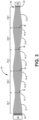
FIG. 3 is a simplified illustration of a braided article covering the multi-mandrel assembly ofFIG. 1 -
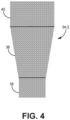
FIG. 4 is a simplified illustration of one preform segment cut from the braided article ofFIG. 3 . -
FIG. 5 is a schematic illustration of an automated braiding system incorporating the multi-mandrel assembly ofFIG. 1 . - While the above-identified figures set forth one or more embodiments of the present disclosure, other embodiments are also contemplated, as noted in the discussion. In all cases, this disclosure presents the invention by way of representation and not limitation. It should be understood that numerous other modifications and embodiments can be devised by those skilled in the art, which fall within the scope and spirit of the principles of the invention. The figures may not be drawn to scale, and applications and embodiments of the present invention may include features and components not specifically shown in the drawings.
- This disclosure presents a multi-mandrel assembly for fabricating multiple CMC parts in a single braiding process. Fabrication of CMC parts may begin with forming a fibrous ceramic fabric into the geometry of the part to be produced (i.e., a preform). For hollow parts, ceramic (e.g., silicon carbide) fibers can be braided or woven around a mandrel to form a fiber preform. The geometry of the mandrel is analogous to the geometry of the part such that the fiber preform takes the shape of the part. Subsequently, one or more interface coatings are applied to the fiber preform, followed by densification with a ceramic matrix material (e.g., silicon carbide) via chemical vapor infiltration (CVI) to form the final or near final part. This fabrication process, however, can be time-consuming and wasteful of the ceramic fibers. For instance, there may be substantial set-up time of the machinery for each mandrel to apply the ceramic fibers. Moreover, there is a lead-in region to each mandrel where the braiding or weaving is started before the geometry of the article. The lead-in region is not part of the final article and is thus removed later on, thereby resulting ceramic fiber waste.
-
FIG. 1 is a simplified illustration ofmandrel assembly 10 intended to overcome many of the aforementioned challenges.Mandrel assembly 10 can be formed by connecting individual mandrels 12-1 through 12-5 (collectively and/or generically referred to as "mandrels 12") in an end-to-end manner along axis A with intervening transition pieces 14-1 through 14-4 (collectively and/or generically referred to as "transition pieces 14").Assembly 10 further includes lead-inextension 16 andend extension 18 at respective first andsecond ends mandrel assembly 10. The outer surface ofmandrel assembly 10 transitions repeatedly between first dimension D1 and second, smaller dimension D2. As used herein, "dimension" can refer to a diameter, for more rounded pieces, or a length, for example, of a cross-sectional plane, along a perimeter, etc. Lead-inextension 16 and transition pieces 14-2 and 14-4 can have generally uniform dimensions in the axial direction equivalent to D1.End extension 18 and transition pieces 14-1 and 14-2 can also have uniform dimensions in the axial direction equivalent to D2. Eachmandrel 12 can transition from D1 to D2 or vice versa. Eachmandrel 12 can be physically in contact with a suitably sized transition piece 14 (including lead-inextension 16 and end extension 18). More specifically, mandrel 12-1 is in contact with and disposed axially between lead-inextension 16 and transition piece 14-1, mandrel 12-2 is in contact with and disposed axially between transition piece 14-1 and transition piece 14-2, mandrel 12-3 is in contact with and disposed axially between transition piece 14-2 and transition piece 14-3, mandrel 12-4 is in contact with and disposed axially between transition piece 14-3 and transition piece 14-4, and mandrel 12-5 is in contact with and disposed axially between transition piece 14-4 andend extension 18.Mandrels 12 are oriented such that they transition axially from tapering to widening in a repeated manner from one mandrel (e.g., mandrel 12-1) to the next (e.g., mandrel 12-2). In an alternative embodiment,mandrel assembly 10 can be oppositely disposed about axis A, that is, withend extension 18 ofFIG. 1 in the lead-in position and lead-inextension 16 ofFIG. 1 in the terminal/end position. In such as embodiment, the first mandrel would widen from the lead-in position to the first transition piece, rather than taper, as shown inFIG. 1 . -
Mandrels 12 can be removably attached tocorresponding transition pieces 14, lead-inextension 16, and/orend extension 18 using connection means, such as tangs, clips, or male/female connectors, including threaded fasteners and pin-slot arrangements.FIG. 2 is a simplified exploded view of mandrel 12-2 and transition piece 14-2 showing one example of connection means 24 aspins 26 on mandrel 12-2 configured to mate with corresponding slots 28 (represented in dashed lines) on transition piece 14-2.Mandrel assembly 10 can be assembled by connecting first mandrel 12-1 to lead-inextension 16, followed by transition piece 14-1 and so on, until the desired number ofmandrels 12 are included. The attachment ofend extension 18 completesmandrel assembly 10. -
Mandrels 12,transition pieces 14, lead-inextension 16 and/orend extension 18, inclusive of connection means 24, can be formed from graphite, metal, or 3D printed/injection molded plastic. In an exemplary embodiment,mandrels 12 can be made from metal or graphite, and remaining sections made from plastic. Metallic andgraphite mandrels 12 are better suited to retain braided parts for subsequent processing (e.g., debulking, chemical vapor infiltration), while the remaining components, which do not always perform well being exposed to chemicals or elevated pressures and temperatures, can be less expensively produced from plastic. In another embodiment,mandrel assembly 10 can be entirely formed from a single material. For example,mandrel assembly 10 can be formed from plastic with eachmandrel 12 being 3D printed to the desired dimensions of a CMC part. -
FIG. 3 is a simplified illustration ofbraided article 30, continuously formed overmandrel assembly 10. The braiding process can begin with braiding ceramic fibers onto lead-inextension 16. These initial fibers can be secured inplace using tape 32 to facilitate further braiding, which progresses axially alongmandrel assembly 10. In an alternative embodiment,tape 32 can instead be another suitable means for securing ceramic fibers to lead inextension 16, such as clamps or glue. The tension of fibers on the braider can be adjusted to allowbraided article 30 to conform to the repeated tapering and widening caused by the arrangement ofmandrels 12 andtransition pieces 14. Tape 32 (or clamps, glue, etc.) can be applied to the final fibers braided overend extension 18 such that both ends of braidedarticle 30 are secured tomandrel assembly 10 for subsequent processing. One such processing step includes the cutting of braidedarticle 30 into multiple preform segments (collectively and/or generically referred to as "preform segments 34"), each of which can be subsequently shaped into a preform and densified to form a CMC part. More specifically,mandrel assembly 10 is configured to produce five preform segments 34-1 through 34-5. Cutting can occur ontransition pieces 14, and more specifically, generally at an axial midpoint M of eachtransition piece 14, represented inFIG. 3 by dashed lines. As such, eachpreform segment 34 includes braided fabric from a portion (i.e., half) of two separate transition pieces 14 (including lead-inextension 16 and end extension 18), one with dimension D1 and the other with dimension D2, and a whole mandrel. Eachpreform segment 34 can be completely separated from adjacent preform segment(s) 34 after cutting.Tape 32 and any adhered fibers are also cut and separated from theadjacent preform segment 34. By comparison, fabricating fivesuch preform segments 34 using an individual mandrel for each (i.e. using conventional methods) would generate five times the fabric waste fromtape 32 and increase processing time due to the need to install and remove each mandrel. -
FIG. 4 is a simplified illustration of preform segment 34-2 rotated counterclockwise 90 degrees from the orientation ofFIG. 3 . With continued reference toFIG. 3 , preform segment 34-2 can be formed into an airfoil-containing part, such as a vane for a gas turbine engine. Braided fabric from the underlying mandrel (i.e., 12-2) becomesairfoil portion 36, braided fabric from the underlying transition pieces (i.e., 14-1 and 14-2) becomes inner diameter (ID)platform portion 38 and outer diameter (OD)platform portion 40, respectively. Additional ceramic fabric (e.g., plies, space-filling inserts, etc.) can be combined with preform segment 34-2 as necessary to fabricate a vane preform. Arrangingmandrels 12 in the repeating tapering-to-widening manner, as discussed above with respect toFIG. 1 , and the use of the appropriately sizedintervening transition pieces 14 prevents sharp/abrupt dimensional transitions alongmandrel assembly 10. Such abrupt transitions can be difficult to braid and can lead to defects in the resultingpreform segments 34. -
FIG. 5 is a simplified illustration ofautomated braiding system 42 incorporatingmandrel assembly 10.System 42 can includerobotic arm 44,mandrel assembly 10,radial braider 46,applicator 48,debulking tool 50, cutting device 52, andoptical device 54.Mandrel assembly 10 can be removably connected torobotic arm 44, which can rotatemandrel assembly 10 about axis A, and translate generally in three dimensions.Applicator 48 can be used to apply a polymer binder to the ceramic fabric,debulking tool 50 can debulk the ceramic fabric, and cutting device 52 can cut braided article 30 (FIG. 3 ) into individual preform segments, without the need to transfer braidedarticle 30 to another location.Optical device 54 can be used to inspect braided layer(s) 32 for defects in the braid pattern, braid angle, thickness, etc. - It should be understood that the disclosed mandrel assembly can include any number of mandrels (e.g., 12-1, 12-2, .... 12-n) of various geometries (disparate or uniform) with any necessary transition pieces. For a mandrel assembly with an even number (e.g., four) mandrels, the lead-in and end extensions can have the same uniform dimensions (e.g., D1), depending on the orientation of the individual mandrels. In general, the mandrel assembly is constrained to an overall length (i.e., along axis A) that can be supported by the braiding apparatus. Such a length could be up to five feet (1.52 m) depending on the weight of
mandrel assembly 10, and could include tens of mandrels for fabricating as many parts from one braiding process. - The disclosed mandrel assembly can be used to form features in CMC components for use in aerospace, maritime, or industrial equipment, to name a few, non-limiting examples.
- The following are non-exclusive descriptions of possible embodiments of the present invention.
- A system for forming multiple braided preform segments includes a mandrel assembly disposed along a mandrel axis, a radial braider for winding fibers onto the mandrel assembly to form a continuous braided article, an applicator for applying a polymer binder to the braided article while mounted on the mandrel assembly, and a debulking tool for debulking the braided article while mounted on the mandrel assembly. The mandrel assembly includes a lead-in extension defining a first end, an end extension defining a second end, and a plurality of mandrels removably connected to a plurality of transition pieces and disposed axially between the lead-in extension and the end extension.
- The system of the preceding paragraph can optionally include any one or more of the following features, configurations and/or additional components:
In the above system, a first mandrel of the plurality of mandrels can be removably connected to the lead-in extension, a first transition piece of the plurality of transition pieces can be removably connected to the first mandrel opposite the lead-in extension, and a second mandrel of the plurality of mandrels can be removably connected to the first transition piece opposite the first mandrel. - In any of the above systems, the first mandrel can be disposed such that it tapers from the lead-in extension to the first transition piece, and the second mandrel can be disposed such that it widens from the first transition piece toward the end extension.
- In any of the above systems, the lead-in extension can have a uniform first dimension, and wherein the first transition piece can have a uniform second dimension, the second dimension being less than the first dimension.
- In any of the above systems, the first mandrel can taper from the first dimension to the second dimension, and the second mandrel can widen from the second dimension to the first dimension.
- In any of the above systems, each of a first subset of the plurality of transition pieces can have the uniform first dimension, and each of a second subset of the plurality of transition pieces can have the uniform second dimension.
- In any of the above systems, the first mandrel can be disposed such that it widens from the lead-in extension to the first transition piece, and the second mandrel can be disposed such that it tapers from the first transition piece toward the end extension.
- In any of the above systems, the plurality of mandrels can be formed from at least one of graphite, a metallic material, and plastic.
- In any of the above systems, the plurality of transition pieces can be formed from at least one of graphite, a metallic material, and plastic.
- In any of the above systems, the plurality of mandrels can include five mandrels.
- Any of the above systems can further include a robotic arm from translating and rotating the mandrel assembly.
- Any of the above systems can further include a cutting device for cutting the braided article into a plurality of preform segments.
- Any of the above systems can further include an optical device for inspecting the braided article.
- A method of forming multiple CMC parts from a braided article includes assembling a mandrel assembly, the mandrel assembly including a lead-in extension, an end extension, and a plurality of mandrels removably connected to a plurality of transition pieces and disposed axially between the lead-in extension and the end extension. The method further includes incorporating the mandrel assembly into a braiding system, forming a continuous braided article over the plurality of mandrels and the plurality of transition pieces, cutting the braided article into a plurality of preform segments, forming a corresponding plurality of preforms from the plurality of preform segments, densifying the plurality of preforms with a ceramic matrix.
- The system of the preceding paragraph can optionally include any one or more of the following features, configurations and/or additional steps:
In the above method, assembling the mandrel assembly can include removably connecting a first mandrel of the plurality of mandrels to the lead-in extension, removably connecting a first transition piece of the plurality of transition pieces to the first mandrel opposite the lead-in extension, and removably connecting a second mandrel of the plurality of mandrels to the first transition piece opposite the first mandrel. - In any of the above methods, assembling the mandrel assembly can further include disposing the first mandrel such that it tapers from the lead-in extension to the first transition piece, and disposing the second mandrel such that it widens from the first transition piece toward the end extension.
- In any of the above methods, assembling the mandrel assembly can further include disposing the first mandrel such that it widens from the lead-in extension to the first transition piece, and disposing the second mandrel such that it tapers from the first transition piece toward the end extension.
- In any of the above methods, cutting the braided article can include cutting along an axial midpoint of each of the plurality of transition pieces.
- In any of the above methods, the plurality of preform segments can include five preform segments.
- In any of the above methods, the plurality of preforms can be densified using chemical vapor infiltration.
- While the invention has been described with reference to an exemplary embodiment(s), it will be understood by those skilled in the art that various changes may be made and equivalents may be substituted for elements thereof without departing from the scope of the invention. In addition, many modifications may be made to adapt a particular situation or material to the teachings of the invention without departing from the essential scope thereof. Therefore, it is intended that the invention not be limited to the particular embodiment(s) disclosed, but that the invention will include all embodiments falling within the scope of the appended claims.
Claims (15)
- A system (42) for forming multiple braided preform segments (34), the system (42) comprising:a mandrel assembly (10) disposed along a mandrel axis (A), the mandrel assembly (10) comprising:a lead-in extension (16) defining a first end;an end extension (18) defining a second end; anda plurality of mandrels (12) removably connected to a plurality of transition pieces (14) and disposed axially between the lead-in extension (16) and the end extension (18);a radial braider (46) for winding fibers onto the mandrel assembly (10) to form a continuous braided article (30);an applicator (48) for applying a polymer binder to the braided article (30) while mounted on the mandrel assembly (10); anda debulking tool (50) for debulking the braided article (30) while mounted on the mandrel assembly (10).
- The system (42) of claim 1, wherein:a first mandrel (12-1) of the plurality of mandrels (12) is removably connected to the lead-in extension (16);a first transition piece (14-1) of the plurality of transition pieces (14) is removablyconnected to the first mandrel (12) opposite the lead-in extension (16); and a second mandrel (12-2) of the plurality of mandrels (12) is removably connectedto the first transition piece (14) opposite the first mandrel (12).
- The system (42) of claim 2, wherein:the first mandrel (12-1) is disposed such that it tapers from the lead-in extension (16) to the first transition piece (14-1); andthe second mandrel (12-2) is disposed such that it widens from the first transition piece (14-1) toward the end extension (18).
- The system (42) of claim 3, wherein the lead-in extension (16) has a uniform first dimension (D1), and wherein the first transition piece (14-1) has a uniform second dimension (D2), the second dimension (D2) being less than the first dimension (D1).
- The system (42) of claim 4, wherein the first mandrel (12-1) tapers from the first dimension (D1) to the second dimension (D2), and wherein the second mandrel (12-2) widens from the second dimension (D2) to the first dimension (D1).
- The system (42) of claim 4 or 5, wherein each of a first subset of the plurality of transition pieces (14) has the uniform first dimension (D1), and wherein each of a second subset of the plurality of transition pieces (14) has the uniform second dimension (D2).
- The system (42) of claim 2, wherein:the first mandrel (12-1) is disposed such that it widens from the lead-in extension (16) to the first transition piece (14-1); andthe second mandrel (12-2) is disposed such that it tapers from the first transition piece (14-1) toward the end extension (18).
- The system (42) of any preceding claim, wherein:the plurality of mandrels (12) are formed from at least one of graphite, a metallic material, and plastic; and/orthe plurality of transition pieces (14) are formed from at least one of graphite, a metallic material, and plastic.
- The system (42) of any preceding claim, wherein the plurality of mandrels (12) comprises five mandrels (12).
- The system (42) of any preceding claim, further comprising: a robotic arm (44) for translating and rotating the mandrel assembly (10).
- The system (42) of any preceding claim, further comprising:a cutting device (52) for cutting the braided article (30) into a plurality of preform segments (34); and/oran optical device (54) for inspecting the braided article (30).
- A method of forming multiple CMC parts from a braided article (30), the method comprising:assembling a mandrel assembly (10), the mandrel assembly (10) comprising:a lead-in extension (16);an end extension (18); anda plurality of mandrels (12) removably connected to a plurality of transition pieces (14) and disposed axially between the lead-in extension (16) and the end extension (18);incorporating the mandrel assembly (10) into a braiding system (42);forming a continuous braided article (30) over the plurality of mandrels (12) and the plurality of transition pieces (14);cutting the braided article (30) into a plurality of preform segments (34);forming a corresponding plurality of preforms from the plurality of preform segments (34); anddensifying the plurality of preforms with a ceramic matrix.
- The method of claim 12, wherein assembling the mandrel assembly (10) comprises:removably connecting a first mandrel (12-1) of the plurality of mandrels (12) to the lead-in extension (16);removably connecting a first transition piece (14-1) of the plurality of transition pieces (14) to the first mandrel (12-1) opposite the lead-in extension (16); andremovably connecting a second mandrel (12-2) of the plurality of mandrels (12) to the first transition piece (14-1) opposite the first mandrel (12),wherein, optionally, assembling the mandrel assembly (10) further comprises:disposing the first mandrel (12-1) such that it tapers from the lead-in extension (16) to the first transition piece (14-1), and disposing the second mandrel (12-2) such that it widens from the first transition piece (14-1) toward the end extension (18); ordisposing the first mandrel (12-1) such that it widens from the lead-in extension (16) to the first transition piece (14-1), and disposing the second mandrel (12-2) such that it tapers from the first transition piece (14-1) toward the end extension (18).
- The method of claim 12 or 13, wherein cutting the braided article (30) comprises cutting along an axial midpoint (M) of each of the plurality of transition pieces (14),
wherein, optionally, the plurality of preform segments (34) comprises five preform segments (34). - The method of claim 12, 13 or 14, wherein the plurality of preforms are densified using chemical vapor infiltration.
Applications Claiming Priority (1)
| Application Number | Priority Date | Filing Date | Title |
|---|---|---|---|
| US18/236,261 US12565451B2 (en) | 2023-08-21 | 2023-08-21 | Multi-mandrel braiding process |
Publications (2)
| Publication Number | Publication Date |
|---|---|
| EP4523895A2 true EP4523895A2 (en) | 2025-03-19 |
| EP4523895A3 EP4523895A3 (en) | 2025-06-18 |
Family
ID=92503832
Family Applications (1)
| Application Number | Title | Priority Date | Filing Date |
|---|---|---|---|
| EP24195676.2A Pending EP4523895A3 (en) | 2023-08-21 | 2024-08-21 | Multi-mandrel braiding process |
Country Status (2)
| Country | Link |
|---|---|
| US (1) | US12565451B2 (en) |
| EP (1) | EP4523895A3 (en) |
Family Cites Families (14)
| Publication number | Priority date | Publication date | Assignee | Title |
|---|---|---|---|---|
| EP0590032B1 (en) | 1991-05-24 | 1999-04-28 | Dow-United Technologies Composite Products, Inc. | Braided complex composite parts and methods of forming same |
| JP2001206778A (en) | 2000-01-24 | 2001-07-31 | Ishikawajima Harima Heavy Ind Co Ltd | Method and apparatus for manufacturing fiber-reinforced composite member |
| JP2010522108A (en) * | 2006-08-17 | 2010-07-01 | ベル ヘリコプター テクストロン インコーポレイテッド | Composite-steel hybrid mast for rotorcraft |
| FR2974026B1 (en) * | 2011-04-13 | 2014-09-19 | Snecma | MACHINE FOR WINDING A FIBROUS TEXTURE ON AN IMPREGNATION CHUCK |
| US9689265B2 (en) | 2012-04-09 | 2017-06-27 | General Electric Company | Thin-walled reinforcement lattice structure for hollow CMC buckets |
| US9816210B2 (en) * | 2015-04-03 | 2017-11-14 | A&P Technology, Inc. | Braided structures of complex geometry |
| JP2017110519A (en) | 2015-10-02 | 2017-06-22 | ザ・ボーイング・カンパニーThe Boeing Company | Induction consolidation for wind turbine blade fabrication |
| US11104032B2 (en) | 2018-04-19 | 2021-08-31 | General Electric Company | Tooling assembly having cam closing feature |
| US11015415B2 (en) | 2018-05-16 | 2021-05-25 | Nine Downhole Technologies, Llc | Filament-reinforced composite material with load-aligned filament windings |
| US11534986B2 (en) * | 2018-11-02 | 2022-12-27 | The Boeing Company | Composite structures constructed of wound tubular braiding |
| US11365635B2 (en) * | 2019-05-17 | 2022-06-21 | Raytheon Technologies Corporation | CMC component with integral cooling channels and method of manufacture |
| US11396814B2 (en) | 2020-06-03 | 2022-07-26 | Raytheon Technologies Corporation | Multi-piece mandrel for CMC components |
| US11608748B2 (en) | 2021-06-04 | 2023-03-21 | Raytheon Technologies Corporation | Preform crossovers for composite airfoils |
| US12397468B2 (en) * | 2022-10-31 | 2025-08-26 | Rtx Corporation | Method for forming multiple ceramic matrix composite articles |
-
2023
- 2023-08-21 US US18/236,261 patent/US12565451B2/en active Active
-
2024
- 2024-08-21 EP EP24195676.2A patent/EP4523895A3/en active Pending
Also Published As
| Publication number | Publication date |
|---|---|
| US12565451B2 (en) | 2026-03-03 |
| EP4523895A3 (en) | 2025-06-18 |
| US20250066259A1 (en) | 2025-02-27 |
Similar Documents
| Publication | Publication Date | Title |
|---|---|---|
| CA2331945C (en) | Manufacturing method and apparatus of fiber reinforced composite member | |
| US5018271A (en) | Method of making a composite blade with divergent root | |
| RU2523308C2 (en) | Production of turbomachine blade from composite | |
| US6627019B2 (en) | Process for making ceramic matrix composite parts with cooling channels | |
| US9539787B2 (en) | Multilayer woven fibrous structure including a hollow tubular part, production method thereof and composite part comprising same | |
| US20160214283A1 (en) | Composite tool and method for forming composite components | |
| US5013216A (en) | Composite blade perform with divergent root | |
| JP6124529B2 (en) | Improved method of manufacturing parts having tubular geometry made from ceramic matrix composites | |
| US5049036A (en) | Composite blade with divergent root and method for making same | |
| US11465316B2 (en) | Additively manufactured mandrels and related methods | |
| CA3039385A1 (en) | Filament-reinforced composite material with load-aligned filament windings | |
| US12528228B2 (en) | Methods for complex geometry mandrel removal of ceramic matrix composite components | |
| EP4098417B1 (en) | Method of forming a ceramic matrix composite component having an internal cooling circuit | |
| EP4454842A1 (en) | Z-channel creation in woven preform by incorporation of pin features into preform tooling | |
| US12565451B2 (en) | Multi-mandrel braiding process | |
| US20200254698A1 (en) | Production in composite material of a lobed structure of a flow mixer | |
| CN113365802A (en) | Shell made of composite material with local thickness variation | |
| JP2001206779A (en) | Method and apparatus for manufacturing fiber-reinforced composite member | |
| CN109109350B (en) | Method for in-process formation of complex shaped rigid composite pipes | |
| US20240391837A1 (en) | Method for braiding automation for ceramic matrix composites | |
| US12435008B2 (en) | Auxetic materials and structures for ceramic matrix composite airfoil mandrels | |
| US12251890B2 (en) | Method for producing a preform for part of a blade or propeller by winding a weave obtained by weaving to shape | |
| CN114174576A (en) | Method for producing a ring segment | |
| US20250128453A1 (en) | Pre-shaped space fillers for small cross section features | |
| CN121511163A (en) | A method for manufacturing a mechanical component made of a composite material, the mechanical component having a hole formed by two fiber preforms. |
Legal Events
| Date | Code | Title | Description |
|---|---|---|---|
| PUAI | Public reference made under article 153(3) epc to a published international application that has entered the european phase |
Free format text: ORIGINAL CODE: 0009012 |
|
| STAA | Information on the status of an ep patent application or granted ep patent |
Free format text: STATUS: THE APPLICATION HAS BEEN PUBLISHED |
|
| AK | Designated contracting states |
Kind code of ref document: A2 Designated state(s): AL AT BE BG CH CY CZ DE DK EE ES FI FR GB GR HR HU IE IS IT LI LT LU LV MC ME MK MT NL NO PL PT RO RS SE SI SK SM TR |
|
| PUAL | Search report despatched |
Free format text: ORIGINAL CODE: 0009013 |
|
| AK | Designated contracting states |
Kind code of ref document: A3 Designated state(s): AL AT BE BG CH CY CZ DE DK EE ES FI FR GB GR HR HU IE IS IT LI LT LU LV MC ME MK MT NL NO PL PT RO RS SE SI SK SM TR |
|
| RIC1 | Information provided on ipc code assigned before grant |
Ipc: C04B 35/565 20060101ALI20250509BHEP Ipc: B29C 53/82 20060101ALI20250509BHEP Ipc: B28B 21/48 20060101ALI20250509BHEP Ipc: B29C 70/32 20060101AFI20250509BHEP |
|
| STAA | Information on the status of an ep patent application or granted ep patent |
Free format text: STATUS: REQUEST FOR EXAMINATION WAS MADE |
|
| 17P | Request for examination filed |
Effective date: 20251218 |