EP4523853A1 - A power tool, a handle for a power tool and a method of assembly - Google Patents
A power tool, a handle for a power tool and a method of assembly Download PDFInfo
- Publication number
- EP4523853A1 EP4523853A1 EP23197900.6A EP23197900A EP4523853A1 EP 4523853 A1 EP4523853 A1 EP 4523853A1 EP 23197900 A EP23197900 A EP 23197900A EP 4523853 A1 EP4523853 A1 EP 4523853A1
- Authority
- EP
- European Patent Office
- Prior art keywords
- handle
- power tool
- housing
- slot
- component
- Prior art date
- Legal status (The legal status is an assumption and is not a legal conclusion. Google has not performed a legal analysis and makes no representation as to the accuracy of the status listed.)
- Pending
Links
Images


Classifications
-
- H—ELECTRICITY
- H01—ELECTRIC ELEMENTS
- H01H—ELECTRIC SWITCHES; RELAYS; SELECTORS; EMERGENCY PROTECTIVE DEVICES
- H01H9/00—Details of switching devices, not covered by groups H01H1/00 - H01H7/00
- H01H9/02—Bases, casings, or covers
- H01H9/06—Casing of switch constituted by a handle serving a purpose other than the actuation of the switch, e.g. by the handle of a vacuum cleaner
-
- B—PERFORMING OPERATIONS; TRANSPORTING
- B25—HAND TOOLS; PORTABLE POWER-DRIVEN TOOLS; MANIPULATORS
- B25F—COMBINATION OR MULTI-PURPOSE TOOLS NOT OTHERWISE PROVIDED FOR; DETAILS OR COMPONENTS OF PORTABLE POWER-DRIVEN TOOLS NOT PARTICULARLY RELATED TO THE OPERATIONS PERFORMED AND NOT OTHERWISE PROVIDED FOR
- B25F5/00—Details or components of portable power-driven tools not particularly related to the operations performed and not otherwise provided for
- B25F5/02—Construction of casings, bodies or handles
-
- B—PERFORMING OPERATIONS; TRANSPORTING
- B27—WORKING OR PRESERVING WOOD OR SIMILAR MATERIAL; NAILING OR STAPLING MACHINES IN GENERAL
- B27C—PLANING, DRILLING, MILLING, TURNING OR UNIVERSAL MACHINES FOR WOOD OR SIMILAR MATERIAL
- B27C5/00—Machines designed for producing special profiles or shaped work, e.g. by rotary cutters; Equipment therefor
- B27C5/10—Portable hand-operated wood-milling machines; Routers
-
- H—ELECTRICITY
- H01—ELECTRIC ELEMENTS
- H01H—ELECTRIC SWITCHES; RELAYS; SELECTORS; EMERGENCY PROTECTIVE DEVICES
- H01H9/00—Details of switching devices, not covered by groups H01H1/00 - H01H7/00
- H01H9/02—Bases, casings, or covers
- H01H9/06—Casing of switch constituted by a handle serving a purpose other than the actuation of the switch, e.g. by the handle of a vacuum cleaner
- H01H2009/066—Casing of switch constituted by a handle serving a purpose other than the actuation of the switch, e.g. by the handle of a vacuum cleaner having switches mounted on a control handle, e.g. gear shift lever
Definitions
- the present disclosure relates to a power tool.
- the present disclosure relates to routers.
- a power tool such as a router may be utilized by tradesmen, craftsmen, hobbyists and other users to perform various tasks. For instance, a router may be used to perform intricate cutting projects, such as decorative profiles and trimming laminates on the edges or perimeters of a workpiece. A router also may be utilized to form grooved areas in woodworking and other material as well as to remove excess material on workpieces. Routers may utilize various types of cutting tools or router bits in order to perform these and other types of tasks.
- a trigger switch is provided for the user to control the operation of the router.
- the trigger switch is mounted in a handle mounted to the main housing of the router and must be connected to the motor and circuit unit. The assembly of the trigger switch in the handle is time consuming and difficult.
- a power tool comprising a housing, at least one handle mountable to the housing, a motor mounted in the housing and electrically connected to a power source, and at least one component with at least one electrical connection electrically connected to the power source.
- the handle comprises an internal cavity, and the component is mountable within the internal cavity.
- the handle also comprises a handle slot configured to receive the electrical connection when the component is mounted within the handle. This aspect allows for easier assembly and attachment of power cables and electronic components within the handle.
- the handle slot is configured to receive the electrical connection when the handle is mounted to the housing. This provides a more secure and stable connection between the handle and the housing.
- a handle slot insert is configured to engage the handle slot and fill the slot.
- the handle slot insert comprises at least one projecting lip configured to engage an internal shoulder portion of the handle. This ensures a secure fit of the insert within the handle slot.
- the handle slot extends at least partially around the periphery of the handle.
- a portion of the handle slot extends in a direction parallel with the handle axis. This provides a more streamlined and efficient design for the power tool.
- the handle slot insert is configured to slide into engagement with the handle slot in a direction parallel with the handle axis. This allows for easy assembly and disassembly of the power tool.
- the handle comprises a handle body portion mountable to the housing and a cap portion mountable on the handle body portion. This provides a more secure and stable connection between the handle and the housing.
- the cap is configured to be mounted to the handle body portion and prevent the handle slot insert from sliding out of the handle slot.
- the handle slot extends along the entire side of the handle body portion. This provides a more versatile and adaptable design for various power tool configurations.
- the cap portion seals an end of the housing body portion when mounted to the housing body portion. This helps to protect the internal components of the power tool from dust and debris.
- the handle slot insert seals the handle slot when in engagement with the handle slot. This provides additional protection for the electrical connection.
- the electrical connection is a plurality of wires.
- the component is a trigger switch.
- the handle comprises a "T" shape. This provides a more ergonomic and comfortable grip for the user.
- the power tool is a router.
- This disclosure is particularly well-suited for use in routers, but may also be applied to other power tools.
- the electrical connection is connected via at least one folded electrical tab.
- a handle mountable on a housing of a power tool having a motor mounted in the housing and electrically connected to a power source comprising an internal cavity configured to receive at least one component with at least one electrical connection electrically connected to the power source and is mountable within the internal cavity.
- the handle also comprises a handle slot configured to receive the electrical connection when the component is mounted within the handle.
- a method of assembling a power tool comprises mounting a motor in a housing, electrically connecting at least one component with the power source with at least one electrical connection, inserting the component in an internal cavity of at least one handle and mounting the handle to the housing, and passing the electrical connection through the handle slot after mounting the handle to the housing.
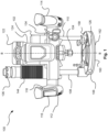
- Figure 1 shows a front view of a power tool 100 according to an example.
- Figures 3 , 4 and 5 also respectively show a plan view, a side view and a perspective view of the same power tool 100.
- the power tool 100 as shown in Figure 1 is a router 100. Whilst the power tool 100 can be a router 100, in other examples any other type of power tool can be used such as a plunge saw, a drill, a multitool, or an oscillating tool mounted on a plunge base portion 106. Hereinafter, the term power tool 100 will be used.
- the power tool 100 comprises a housing 102.
- the housing 102 comprises a clam shell type construction having two halves which are fastened together.
- the halves of the housing 102 are fastened together with screws but in alternative examples any suitable means for fastening the housing 102 together may be used such as glue, clips, bolts and so on.
- any suitable means for fastening the housing 102 together may be used such as glue, clips, bolts and so on.
- the fastenings in the housing 102 are not shown.
- a motor 120 (best shown in Figure 2 ) is mounted in the housing 102 for driving a collet 104.
- the motor 120 is optionally mounted within a motor housing 150 (best shown in Figure 6 ).
- the motor housing 150 may be mounted to the housing 102.
- the motor 120 may be any suitable type of electric motor, such as a brushed or brushless DC motor, an AC motor, a stepper motor, or other types of motors known in the art.
- the motor housing 150 is mounted to the housing 102 via dampeners e.g. rubber mounts (not shown) to reduce the vibration transmitted from the motor 120 to the housing 102 and, in turn, to the user.
- the motor 120 is operatively connected to the collet 104 through a drive shaft 156, which transmits the rotational movement of the motor 120 directly to the tool holder e.g., the collet 104.
- the drive shaft 156 may comprise one or more bearings to decrease friction and ensure smooth rotation of the collet 104.
- the motor 120 may comprise various cooling components, such as fans or cooling fins, to dissipate heat generated during operation.
- various cooling components such as fans or cooling fins, to dissipate heat generated during operation.
- One such fan 164 is shown in Figure 6 .
- These cooling components may be encased within the motor housing 150 or the housing 102 of the power tool 100 and may be integrated into the design of the motor 120 itself.
- a cutting tool bit (not shown) can be mounted in the collet 104 for engaging a workpiece (not shown).
- the cutting tool is a cutting tool bit for a power tool 100.
- the cutting tool bit is a router bit such as an upcut spiral router bit, a downcut spiral router bit, a straight router bit, a cove router bit, a chamfer router bit, a rabbeting router bit, a roundover router bit, a beading router bit, an ogee router bit or a panel raising router bit. Any other suitable router cutting tool bit can be mounted in the collet 104.
- the collet 104 may be a cylindrical component that contains an inner bore to accommodate and grip the shank of the cutting tool bit.
- the collet 104 is known and will not be discussed in any further detail.
- the power tool 100 comprises a base portion 106 for engaging the workpiece.
- the base portion 106 comprises a base aperture 126 through which the cutting tool bit can project e.g., when the user plunges the housing 102 towards the base portion 106 and then the cutting tool bit projects through the base aperture 126.
- the base portion 106 is mounted to the housing 102 via first and second guide posts 108, 110.
- the first and second guide posts 108, 110 are slidably mounted to the housing 102 for adjusting the relative distance of the base portion 106 from the collet 104.
- the first and second guide posts 108, 110 are removable. This means that the power tool 100 can be used without the base portion 106 engaging the workpiece.
- the housing 102 comprises a first handle 112 and a second handle 114 for the user to grip during operation.
- the first handle 112 and the second handle 114 have a different arrangement.
- the first handle 112 comprises a component 800 of the power tool 100.
- the component 800 is best shown in Figure 8 .
- the component 800 comprises at least one electrical connection 802 electrically connected with the power source 122 e.g., the battery 122.
- the component 800 is an electrical component.
- the component 800 is an electronic component 800.
- first and second electrical wires 802, 804 need to extend from the first handle 112 to the housing 102.
- first and second electrical wires 802, 804 are respectively connected to the main trigger switch 116 via first and second electrical tabs 822, 824 as shown in Figure 8 .
- the first and second folded electrical tabs 822, 824 are bent through approx. 180 degrees. This allows the main trigger switch 116 to be accommodated into the space inside of the first handle 112.
- the electrical or electronic component 800 is a main trigger switch 116 for operating the power tool 100.
- the first handle 112 also comprises a lock button 118 for selectively locking the main trigger switch 116 into an "ON" status. This means that the user does not have to constantly keep pressure maintained on the main trigger switch 116 during operation of the power tool 100.
- the main trigger switch 116 can be replaced with a momentary switch (not shown).
- the electrical or electronic component 800 can be any other suitable device electrically connected to the power tool 100.
- the electrical or electronic component 800 can be any type of sensor, an LED, a buzzer, or any other device.
- the first handle 112 comprises the component 800
- the second handle 114 can also have the same construction of the first handle 112 as described herein.
- the component 800 mounted in the first handle 112 can be the main trigger switch 116 and the component 800 mounted in the second handle 114 can be e.g., an LED.
- the user can hold both the first handle 112 and the second handle 114 to grip the power tool 100 during operation thereof.
- the first handle 112 and the second handle 114 optionally comprise a clam shell arrangement as shown in Figure 6 .
- the first handle 112 and the second handle 114 comprise a "T-shaped" profile. This means that the first handle 112 and the second handle 114 have an ergonomic profile and are comfortable when the user wraps their fingers and thumbs around the first and second handles 112, 114.
- first handle 112 and the second handle 114 are separate handle elements that are mountable to the housing 102. Separate parts of the first handle 112 and the second handle 114 are shown in Figure 6 . Accordingly, the separate parts of the first handle 112 on the second handle 114 can be assembled before the first and second handles 112, 1140 mounted on the housing 102.
- first and second handles 112, 114 are mounted to the housing 102 with one or more screw fastenings.
- any other type of fastening arrangement can be used, e.g., adhesive, clips, or clamps or a friction fit etc.
- the motor 120 is electrically connected to an electric power source 122.
- the electric power source 122 is a mains electrical supply.
- the electrical power source 122 is a battery 122.
- the battery 122 can be removably mountable to the housing 102 or integral to the housing 102.
- the power tool 100 can be powered either from both a battery 122 and / or a mains electrical supply.
- the motor 120 is connected to a controller 130 (best shown in Figure 2 ) mounted on a PCB in the housing 102.
- the controller 130 is configured to issue control instructions to the motor 120 in dependence of the user actuating the main trigger switch 116.
- the battery 122 as shown in Figure 1 is securely mounted to a top portion 124 of the housing 102.
- the battery 122 is configured to power the motor 120 and other electronic components.
- the battery 122 may comprise lithium-ion cells, nickel-metal hydride cells, or any other type of rechargeable or non-rechargeable power source.
- the power tool 100 as shown in Figure 1 is optionally a plunge router 100. However, in some examples, the power tool 100 is not a plunge router 100. Accordingly, the power tool 100 can be selectively operated in different modes. In a first mode, the power tool 100 is in a locked position. In the locked position, the first and second guide posts 108, 110 are fixed with respect to the housing 102. This means that the housing 102 and the collet 104 are fixed with respect to the base portion 106. Accordingly, the cutting tool (not shown) can be maintained at a set height above the workpiece. This means that the user of the power tool 100 can select how far the cutting tool projects through the aperture in the base portion 106.
- the power tool 100 is in an unlocked position.
- the first and second guide posts 108, 110 are slidable with respect to the housing 102.
- the user can push down on the first and second handles 112, 114 and the first and second guide posts 108, 110 slide into or through the housing 102.
- the distance between the base portion 106 and the housing 102 can be adjusted.
- the user can position the power tool 100 above the workpiece and then push the housing 102 towards the workpiece and the cutting tool plunges into the workpiece.
- the power tool 100 is configured to be set in a plurality of unlocked positions for different operation modes of the power tool 100.
- the user can select between the locked and unlocked position of the power tool 100 by using a locking system 132 (best shown in Figure 6 ) mounted on the power tool 100.
- the locking system 132 is actuatable with a locking lever 134.
- Figure 1 shows the locking lever 134 in a locked position.
- the locking lever 134 is in the locked position in a vertical orientation.
- the locking lever 134 is mechanically coupled to the first and / or second guide posts 108, 110 such that relative movement of the first and second guide posts 108, 110 is prevented when the locking lever 134 is in the locked position.
- the locking lever 134 actuates a locking bolt (not shown) to engage the first guide post 108 or the second guide post 110.
- the locking bolt exerts a frictional force against the first or second guide posts 108, 110 when the locking lever 134 is in the locked position.
- the locking bolt can engage a detent or a hole in the first guide post 108 or the second guide post 110.
- the locking lever 134 when the locking lever 134 is in the locked position the locking bolt clamps against or engages the first or second guide posts 108, 110 preventing relative movement therebetween.
- the locking lever 134 optionally engages a reciprocal hole or detent (not shown) in the second guide post 110 and the housing 102.
- an additional second locking bolt (not shown) is used to also engage with the first guide post 108 such that both the first and the second guide posts 108, 110 are locked at the same time.
- other mechanisms can be used to lock the first and second guide posts 108, 110 such as a latch-catch mechanism, a ball bearing engaging a detent in the first and second guide posts 108, 110 or any other suitable mechanism.
- the locking lever 134 is moveable between the locked position shown in Figure 1 and an unlocked position (not shown). In some examples, the locking lever 134 is rotatable between the locked position and the unlocked position about a rotational axis X-X of the locking lever 134 (as shown in Figure 6 ). In some other examples, the locking lever 134 is slidable between the locked position and the first and second unlocked positions. Mechanical linkages (not shown) may be coupled between the locking lever 134 and the locking bolt for actuating engagement between the locking bolt and the first and second guide posts 108, 110.
- a housing return spring 128 is optionally shown in Figure 2 as is fixed with respect to the first guide post 108 at a first spring end 140 and connected to the housing 102 at a second spring end 142.
- the housing return spring 128 is fixed with respect to the first guide post 108 at a first spring end 140 with a first C-clip 146 and fixed with respect to the housing 102 at a second spring end 142 with a second C-clip 148.
- Other types of fasteners can be used instead of the first and second c-clips 146, 148.
- the housing return spring 128 extends and exerts a return force on the housing 102 to return the unplunged position (e.g., the power tool 100 as shown in Figure 1 ).
- the housing return spring 128 is shrouded with a bellows 144 to prevent ingress of dirt, debris, or moisture into the housing return spring 128 or other parts of the power tool 100.
- the housing 102 comprises a depth rod 152.
- the depth rod 152 is configured to engage one or more depth screws 154 of a plunge depth stop mounted on the base portion 106.
- the housing 102 is prevented from moving further towards the base portion 106 when the depth rod 152 engages the depth screws 154 of the plunge depth stop.
- the amount the depth rod 152 extends towards the base portion 106 is adjustable by the user.
- the amount the depth screws 154 project towards the housing 102 from the base portion 106 are also adjustable by the user.
- only one of the depth screws 154 are labelled.
- the plunge depth stop, the depth screws 154 and the depth rod 152 are known and will not be described in any further detail.
- the power tool 100 comprises a dust extraction conduit 136.
- the dust extraction conduit 136 is connectable to a vacuum source such as a workshop vacuum.
- the first guide post 108 is hollow and comprises a first guide post conduit 138 which is in fluid communication with the dust extraction conduit 136 at a first end of the first guide post 108.
- the second end of the first guide post 108 is in fluid communication with the base portion 106 and the cutting tool.
- the first guide post conduit 138 couples the vacuum source via the dust extraction conduit 136 to the base portion 106.
- a chip collector accessory 300 is optionally removably mountable to the base portion 106 or the sub-base adapter 162.
- the chip collector accessory 300 is mountable to the base portion 106 around the base aperture 126 when mounted directly to the base portion 106.
- chip collector accessory 300 is mountable to the sub-base adapter 162 around the sub-base adapter hole (not shown).
- the base portion 106 provides a stable and flat surface in a plane parallel with axis A-A (as shown in Figure 2 ).
- the base portion 106 is arranged to be positioned and secured against the workpiece during operation of the power tool 100.
- the base portion 106 may comprise a first base side 158 facing away from the workpiece, and a second base side 160 facing towards the workpiece.
- the base portion 106 may be formed from any suitable material such as metal, plastic, composite, or any combination thereof.
- the dimensions and geometrical features of the base portion 106 may be configured to ensure proper compatibility with a variety of accessories, as discussed below.
- the base portion 106 may optionally comprise a plurality of mounting features, such as holes, slots, or recesses, which enable the secure attachment of other components such as a sub-base adapter 162. These mounting features may be arranged in a predetermined pattern or layout, which corresponds to complementary features on the sub-base adapter 162 for proper alignment and mounting.
- the base portion 106 of the power tool 100 may be integrally formed with the housing 102 or may be a separate component that is securely attached or connected to the main body of the housing 102 as shown in the accompanying Figures.
- Figure 12 shows the first guide post 108 and the second guide post 110 fixed with respect to the base portion 106.
- Figure 8 shows an exploded perspective view of the first handle 112.
- Figure 9 shows a cross-sectional side view of the first handle 112.
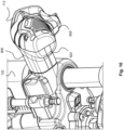
- Figure 10 shows a perspective view of the first handle 112 assembled and mounted on the housing 102.
- the first handle 112 comprises a plurality of parts which are assembled together to form the first handle 112.
- the first handle 112 comprises a handle body portion 806 and a cap portion 808.
- the cap portion 808 is mountable on the handle body portion 806 and fastened thereon with one or more screw fasteners.
- the first handle 112 defines an internal cavity 900 as shown in Figure 9 .
- the internal cavity 900 is configured to receive the component 800 as mentioned above.
- the component 800 is the main trigger switch 116 for actuating the power tool 100.
- the handle body portion 806 comprises a projecting stem sleeve 810 which is configured to engage a reciprocal housing projection 812.
- the reciprocal housing projection 812 is configured to protrude into the projecting stem sleeve 810 of the handle body portion 806.
- the projecting stem sleeve 810 slides over the reciprocal housing projection 812 and is fastened thereto.
- the projecting stem sleeve 810 and the reciprocal housing projection 812 are secured together with one or more screw fasteners.
- the projecting stem sleeve 810 and the reciprocal housing projection 812 can be fastened together in different ways e.g., adhesive, clips, or clamps or a friction fit etc.
- the handle body portion 806 and the cap portion 808 are configured to define the internal cavity 900 and surround the main trigger switch 116 when fastened together.
- the handle body portion 806 comprises a cup portion 816 connected to the projecting stem sleeve 810.
- the cup portion 816 is configured to receive the component 800 e.g., the main trigger switch 116.
- the cup portion 816 of the handle body portion 806 is generally curved and similar in shape to the cap portion 808.
- the internal cavity 900 extends through the middle of the housing body portion 806 and within the projecting stem sleeve 810. This means that the first electrical wire 802 and the second electrical wire 804 can be threaded through the projecting stem sleeve 810.
- the handle body portion 806 and the cap portion 808 generally define a cylindrical, tubular, or barrel shaped volume when fastened together.
- the shape of the handle body portion 806 and the cap portion 808 can be modified to define any suitable internal volume for receiving one or more components 800 in the internal cavity 900.
- One or more features can be provided in the handle body portion 806 and the cap portion 808 for aligning or retaining the main trigger switch 116 before, during and after assembly of the first handle 112.
- the handle body portion 806 comprises a projecting peg which is configured to engage the main trigger switch 116. This holds the main trigger switch 116 and the handle body portion 806 together during assembly.
- the cap portion 808 is configured to mount on the housing body portion 806 and seal an end of the housing body portion 806.
- the main trigger switch 116 as shown in Figure 8 is outside the handle body portion 806 and the cap portion 808. Accordingly, the arrangement as shown in Figure 8 is during assembly of the first handle 112 to the housing 102.
- the main trigger switch 116 is electrically connected to the power source 122 and the electrical circuit (not shown) of the power tool 100.
- the main trigger switch 116 is connected to the electrical circuit via the first electrical wire 802 and the second electrical wire 804.
- the main trigger switch 116 is then placed within the cup portion 816 of the handle body portion 806.
- the first handle 112 comprises a unique arrangement for allowing placement of the first electrical wire 802 and the second electrical wire 804.
- the handle body portion 806 comprises a handle slot 818 configured to receive the first electrical wire 802 and the second electrical wire 804 when the main trigger switch 116 is mounted in the first handle 112 and the main trigger switch 116 is electrically connected to the electrical circuit of the power tool 100.
- the first electrical wire 802 and the second electrical wire 804 can then be fed manually into handle slot 818.
- the handle slot 818 is in communication with the internal cavity 900. Therefore, when the user feeds the first electrical wire 802 and the second electrical wire 804 into the handle slot 818, the first electrical wire 802 and the second electrical wire 804 are placed within the internal cavity 900 together with the main trigger switch 116.
- the handle slot 818 extends along the entire of one side of the handle body portion 806. As can be seen from Figure 8 , the handle slot 818 extends along the underside of the first handle 112. The handle slot 818 extends at least in part in a direction parallel with a first handle axis B-B.
- the first handle axis B-B is the direction that the first handle 112 projects from the housing 102 when mounted to the housing 102.
- the handle slot 818 follows the periphery of the housing body portion 806. Since in some examples the first handle 112 comprises a T-shape, the handle slot 818 can extend in a direction which is not parallel to the first handle axis B-B.
- a handle slot insert 820 is configured to fill the handle slot 818.
- the handle slot insert 820 is configured to slidably engage with the handle slot 818.
- the handle slot insert 820 is configured to slide into engagement with the handle slot 818 in a direction parallel with the first handle axis B-B.
- the cap portion 808 is fastened to the handle body portion 806.
- the cap portion 808 then traps the handle slot insert 820 in the handle slot 818.
- the handle slot insert 820 can be fixed in place with adhesive, clips, or detents or any other mechanism.
- the cap portion 808 overlays the handle slot 818 when the first handle 112 is assembled, additional fastening options for the handle slot insert 820 may not be necessary.
- the handle slot insert 820 is also prevented from moving with respect to the handle slot 818 in a direction perpendicular to the first handle axis B-B.
- the handle slot insert 820 comprises a first and second projecting lip 902, 904 which are configured to engage reciprocal first and second internal shoulder portions 908, 910 in the internal cavity 900. In this way, the first and second projecting lip 902, 904 engage the first and second internal shoulder portions 908, 910 and prevent the handle slot insert 820 from being removed.
- the first handle 112 when the first handle 112 is assembled the first handle 112 is sealed.
- the handle slot insert 820 fills the handle slot 818, the handle slot insert 820 seals the handle slot 818.
- the cap portion 808 engages the handle body portion 806, the cap portion 808 seals the handle body portion 806. This means that the internal cavity 900 in the first handle 112 and the component 800, e.g., the main trigger switch 116 mounted in the internal cavity 900 remain free from dirt.
- the handle slot 818 is filled with silicone, or rubber.
- the first handle 112 is overmolded when assembled and the handle slot 818 is then filled during the overmolding process.
- the handle slot 818 remains unfilled and no handle insert 820 or otherwise is used.
- the following steps are taken when assembling the first handle 112 and the power tool 100.
- the motor 120 is mounted in the housing 102.
- the at least one component 800 is electrically connected with the power source 122 with at least one electrical connection 802, 804.
- the second step can comprise soldering the first and second electrical wires 802, 804 to PCB connected to the electrical circuit of the power tool 100.
- the first and second electrical wires 802, 804 can comprise sliding contacts for engagement with reciprocal clip.
- the at least one component 800 is inserted into the internal cavity 900 of at least one handle 112.
- the at least one handle 112 is mounted to the housing 102.
- the at least one electrical connection 802, 804 is passed through the handle slot 818 after mounting the at least one handle 112 to the housing 102.
- the handle slot insert 820 is inserted into the handle slot 818 and the cap portion 808 is mounted on the housing body portion 806.
Landscapes
- Engineering & Computer Science (AREA)
- Mechanical Engineering (AREA)
- Life Sciences & Earth Sciences (AREA)
- Wood Science & Technology (AREA)
- Forests & Forestry (AREA)
- Portable Power Tools In General (AREA)
Abstract
Description
- The present disclosure relates to a power tool. In particular, the present disclosure relates to routers.
- A power tool such as a router may be utilized by tradesmen, craftsmen, hobbyists and other users to perform various tasks. For instance, a router may be used to perform intricate cutting projects, such as decorative profiles and trimming laminates on the edges or perimeters of a workpiece. A router also may be utilized to form grooved areas in woodworking and other material as well as to remove excess material on workpieces. Routers may utilize various types of cutting tools or router bits in order to perform these and other types of tasks.
- In some routers, as shown in
WO2021/219349 , a trigger switch is provided for the user to control the operation of the router. The trigger switch is mounted in a handle mounted to the main housing of the router and must be connected to the motor and circuit unit. The assembly of the trigger switch in the handle is time consuming and difficult. - It may not be possible to attach electrical wires to the trigger switch after being inserted within the handle because there is limited room within the handle. Furthermore, if the electrical wires are attached before the trigger switch is mounted within the handle, then the overall assembly of the power tool is harder.
- Examples of the present disclosure aim to address the aforementioned problems.
- According to an aspect of the present disclosure there is provided a power tool comprising a housing, at least one handle mountable to the housing, a motor mounted in the housing and electrically connected to a power source, and at least one component with at least one electrical connection electrically connected to the power source. The handle comprises an internal cavity, and the component is mountable within the internal cavity. The handle also comprises a handle slot configured to receive the electrical connection when the component is mounted within the handle. This aspect allows for easier assembly and attachment of power cables and electronic components within the handle.
- Optionally in some examples, the handle slot is configured to receive the electrical connection when the handle is mounted to the housing. This provides a more secure and stable connection between the handle and the housing.
- Optionally in some examples, a handle slot insert is configured to engage the handle slot and fill the slot.
- Optionally in some examples, the handle slot insert comprises at least one projecting lip configured to engage an internal shoulder portion of the handle. This ensures a secure fit of the insert within the handle slot.
- Optionally in some examples, the handle slot extends at least partially around the periphery of the handle.
- Optionally in some examples, a portion of the handle slot extends in a direction parallel with the handle axis. This provides a more streamlined and efficient design for the power tool.
- Optionally in some examples, the handle slot insert is configured to slide into engagement with the handle slot in a direction parallel with the handle axis. This allows for easy assembly and disassembly of the power tool.
- Optionally in some examples, the handle comprises a handle body portion mountable to the housing and a cap portion mountable on the handle body portion. This provides a more secure and stable connection between the handle and the housing.
- Optionally in some examples, the cap is configured to be mounted to the handle body portion and prevent the handle slot insert from sliding out of the handle slot. Optionally in some examples, the handle slot extends along the entire side of the handle body portion. This provides a more versatile and adaptable design for various power tool configurations.
- Optionally in some examples, the cap portion seals an end of the housing body portion when mounted to the housing body portion. This helps to protect the internal components of the power tool from dust and debris.
- Optionally in some examples, the handle slot insert seals the handle slot when in engagement with the handle slot. This provides additional protection for the electrical connection.
- Optionally in some examples, the electrical connection is a plurality of wires.
- Optionally in some examples, the component is a trigger switch.
- Optionally in some examples, the handle comprises a "T" shape. This provides a more ergonomic and comfortable grip for the user.
- Optionally in some examples, the power tool is a router. This disclosure is particularly well-suited for use in routers, but may also be applied to other power tools.
- Optionally in some examples, the electrical connection is connected via at least one folded electrical tab.
- According to a second aspect of the disclosure, a handle mountable on a housing of a power tool having a motor mounted in the housing and electrically connected to a power source is provided. The handle comprises an internal cavity configured to receive at least one component with at least one electrical connection electrically connected to the power source and is mountable within the internal cavity. The handle also comprises a handle slot configured to receive the electrical connection when the component is mounted within the handle.
- According to a third aspect of the disclosure, a method of assembling a power tool is provided. The method comprises mounting a motor in a housing, electrically connecting at least one component with the power source with at least one electrical connection, inserting the component in an internal cavity of at least one handle and mounting the handle to the housing, and passing the electrical connection through the handle slot after mounting the handle to the housing. This method allows for easier assembly and attachment of power cables and electronic components within the handle.
- Various other aspects and further examples are also described in the following detailed description and in the attached claims with reference to the accompanying drawings, in which:
-
Figure 1 shows a front view of a power tool according to an example; -
Figure 2 shows a side cross-sectional view of a power tool according to an example; -
Figure 3 shows plan view of a power tool according to an example; -
Figure 4 shows a side view of a power tool according to an example; -
Figure 5 shows another perspective view of a power tool according to an example; -
Figure 6 shows an exploded perspective view of a power tool according to an example; -
Figure 7 shows an exploded perspective view of the top portion of a power tool according to an example, -
Figure 8 shows an exploded perspective view of a handle of a power tool according to an example; -
Figure 9 shows a cross-sectional view of a handle of a power tool according to an example, and -
Figure 10 shows a close-up perspective view of a power tool according to an example. -
Figure 1 shows a front view of apower tool 100 according to an example.Figures 3 ,4 and5 also respectively show a plan view, a side view and a perspective view of thesame power tool 100. Thepower tool 100 as shown inFigure 1 is arouter 100. Whilst thepower tool 100 can be arouter 100, in other examples any other type of power tool can be used such as a plunge saw, a drill, a multitool, or an oscillating tool mounted on aplunge base portion 106. Hereinafter, theterm power tool 100 will be used. - The
power tool 100 comprises ahousing 102. Thehousing 102 comprises a clam shell type construction having two halves which are fastened together. The halves of thehousing 102 are fastened together with screws but in alternative examples any suitable means for fastening thehousing 102 together may be used such as glue, clips, bolts and so on. For the purposes of clarity, the fastenings in thehousing 102 are not shown. - A motor 120 (best shown in
Figure 2 ) is mounted in thehousing 102 for driving acollet 104. Themotor 120 is optionally mounted within a motor housing 150 (best shown inFigure 6 ). Themotor housing 150 may be mounted to thehousing 102. Themotor 120 may be any suitable type of electric motor, such as a brushed or brushless DC motor, an AC motor, a stepper motor, or other types of motors known in the art. Optionally, themotor housing 150 is mounted to thehousing 102 via dampeners e.g. rubber mounts (not shown) to reduce the vibration transmitted from themotor 120 to thehousing 102 and, in turn, to the user. - The
motor 120 is operatively connected to thecollet 104 through adrive shaft 156, which transmits the rotational movement of themotor 120 directly to the tool holder e.g., thecollet 104. Thedrive shaft 156 may comprise one or more bearings to decrease friction and ensure smooth rotation of thecollet 104. - The
motor 120 may comprise various cooling components, such as fans or cooling fins, to dissipate heat generated during operation. Onesuch fan 164 is shown inFigure 6 . These cooling components may be encased within themotor housing 150 or thehousing 102 of thepower tool 100 and may be integrated into the design of themotor 120 itself. - A cutting tool bit (not shown) can be mounted in the
collet 104 for engaging a workpiece (not shown). Typically, the cutting tool is a cutting tool bit for apower tool 100. In some examples the cutting tool bit is a router bit such as an upcut spiral router bit, a downcut spiral router bit, a straight router bit, a cove router bit, a chamfer router bit, a rabbeting router bit, a roundover router bit, a beading router bit, an ogee router bit or a panel raising router bit. Any other suitable router cutting tool bit can be mounted in thecollet 104. - The
collet 104 may be a cylindrical component that contains an inner bore to accommodate and grip the shank of the cutting tool bit. Thecollet 104 is known and will not be discussed in any further detail. - As shown in
Figure 1 , thepower tool 100 comprises abase portion 106 for engaging the workpiece. Thebase portion 106 comprises abase aperture 126 through which the cutting tool bit can project e.g., when the user plunges thehousing 102 towards thebase portion 106 and then the cutting tool bit projects through thebase aperture 126. Thebase portion 106 is mounted to thehousing 102 via first and second guide posts 108, 110. The first and second guide posts 108, 110 are slidably mounted to thehousing 102 for adjusting the relative distance of thebase portion 106 from thecollet 104. In some examples, the first and second guide posts 108, 110 are removable. This means that thepower tool 100 can be used without thebase portion 106 engaging the workpiece. - The
housing 102 comprises afirst handle 112 and asecond handle 114 for the user to grip during operation. Thefirst handle 112 and thesecond handle 114 have a different arrangement. Thefirst handle 112 comprises acomponent 800 of thepower tool 100. Thecomponent 800 is best shown inFigure 8 . In some examples, thecomponent 800 comprises at least oneelectrical connection 802 electrically connected with thepower source 122 e.g., thebattery 122. In some examples, thecomponent 800 is an electrical component. Alternatively, and some other examples thecomponent 800 is anelectronic component 800. - Since the
component 800 is electrically connected to thepower tool 100, one or more electrical connections e.g., first and secondelectrical wires first handle 112 to thehousing 102. - In some examples, the first and second
electrical wires main trigger switch 116 via first and secondelectrical tabs Figure 8 . The first and second foldedelectrical tabs electrical tabs main trigger switch 116 to be accommodated into the space inside of thefirst handle 112. - In some examples, the electrical or
electronic component 800 is amain trigger switch 116 for operating thepower tool 100. In some examples, thefirst handle 112 also comprises alock button 118 for selectively locking themain trigger switch 116 into an "ON" status. This means that the user does not have to constantly keep pressure maintained on themain trigger switch 116 during operation of thepower tool 100. In some examples, themain trigger switch 116 can be replaced with a momentary switch (not shown). - However, in some alternative examples, the electrical or
electronic component 800 can be any other suitable device electrically connected to thepower tool 100. Example, the electrical orelectronic component 800 can be any type of sensor, an LED, a buzzer, or any other device. Furthermore, whilst the figures show that thefirst handle 112 comprises thecomponent 800, thesecond handle 114 can also have the same construction of thefirst handle 112 as described herein. Indeed, thecomponent 800 mounted in thefirst handle 112 can be themain trigger switch 116 and thecomponent 800 mounted in thesecond handle 114 can be e.g., an LED. - The user can hold both the
first handle 112 and thesecond handle 114 to grip thepower tool 100 during operation thereof. Thefirst handle 112 and thesecond handle 114 optionally comprise a clam shell arrangement as shown inFigure 6 . As shown inFigures 3 and4 , thefirst handle 112 and thesecond handle 114 comprise a "T-shaped" profile. This means that thefirst handle 112 and thesecond handle 114 have an ergonomic profile and are comfortable when the user wraps their fingers and thumbs around the first andsecond handles - Indeed, the
first handle 112 and thesecond handle 114 are separate handle elements that are mountable to thehousing 102. Separate parts of thefirst handle 112 and thesecond handle 114 are shown inFigure 6 . Accordingly, the separate parts of thefirst handle 112 on thesecond handle 114 can be assembled before the first andsecond handles 112, 1140 mounted on thehousing 102. - In some examples, the first and
second handles housing 102 with one or more screw fastenings. In some other examples, any other type of fastening arrangement can be used, e.g., adhesive, clips, or clamps or a friction fit etc. - The
motor 120 is electrically connected to anelectric power source 122. In some examples, theelectric power source 122 is a mains electrical supply. In some other examples, theelectrical power source 122 is abattery 122. Thebattery 122 can be removably mountable to thehousing 102 or integral to thehousing 102. In some examples, thepower tool 100 can be powered either from both abattery 122 and / or a mains electrical supply. Themotor 120 is connected to a controller 130 (best shown inFigure 2 ) mounted on a PCB in thehousing 102. Thecontroller 130 is configured to issue control instructions to themotor 120 in dependence of the user actuating themain trigger switch 116. - The
battery 122 as shown inFigure 1 is securely mounted to atop portion 124 of thehousing 102. Thebattery 122 is configured to power themotor 120 and other electronic components. Thebattery 122 may comprise lithium-ion cells, nickel-metal hydride cells, or any other type of rechargeable or non-rechargeable power source. - The
power tool 100 as shown inFigure 1 is optionally aplunge router 100. However, in some examples, thepower tool 100 is not aplunge router 100. Accordingly, thepower tool 100 can be selectively operated in different modes. In a first mode, thepower tool 100 is in a locked position. In the locked position, the first and second guide posts 108, 110 are fixed with respect to thehousing 102. This means that thehousing 102 and thecollet 104 are fixed with respect to thebase portion 106. Accordingly, the cutting tool (not shown) can be maintained at a set height above the workpiece. This means that the user of thepower tool 100 can select how far the cutting tool projects through the aperture in thebase portion 106. - In a second mode, the
power tool 100 is in an unlocked position. In the unlocked position the first and second guide posts 108, 110 are slidable with respect to thehousing 102. This means that the user can push down on the first andsecond handles housing 102. In this way, the distance between thebase portion 106 and thehousing 102 can be adjusted. This means that the user can position thepower tool 100 above the workpiece and then push thehousing 102 towards the workpiece and the cutting tool plunges into the workpiece. - As discussed hereinafter, the
power tool 100 is configured to be set in a plurality of unlocked positions for different operation modes of thepower tool 100. - The user can select between the locked and unlocked position of the
power tool 100 by using a locking system 132 (best shown inFigure 6 ) mounted on thepower tool 100. In some examples, thelocking system 132 is actuatable with a lockinglever 134. -
Figure 1 shows the lockinglever 134 in a locked position. In some examples, the lockinglever 134 is in the locked position in a vertical orientation. The lockinglever 134 is mechanically coupled to the first and / or second guide posts 108, 110 such that relative movement of the first and second guide posts 108, 110 is prevented when the lockinglever 134 is in the locked position. - In some examples, the locking
lever 134 actuates a locking bolt (not shown) to engage thefirst guide post 108 or thesecond guide post 110. In this way, the locking bolt exerts a frictional force against the first or second guide posts 108, 110 when the lockinglever 134 is in the locked position. Alternatively, the locking bolt can engage a detent or a hole in thefirst guide post 108 or thesecond guide post 110. - Accordingly, when the locking
lever 134 is in the locked position the locking bolt clamps against or engages the first or second guide posts 108, 110 preventing relative movement therebetween. In some examples the lockinglever 134 optionally engages a reciprocal hole or detent (not shown) in thesecond guide post 110 and thehousing 102. In other examples, an additional second locking bolt (not shown) is used to also engage with thefirst guide post 108 such that both the first and the second guide posts 108, 110 are locked at the same time. In other examples, other mechanisms can be used to lock the first and second guide posts 108, 110 such as a latch-catch mechanism, a ball bearing engaging a detent in the first and second guide posts 108, 110 or any other suitable mechanism. - The locking
lever 134 is moveable between the locked position shown inFigure 1 and an unlocked position (not shown). In some examples, the lockinglever 134 is rotatable between the locked position and the unlocked position about a rotational axis X-X of the locking lever 134 (as shown inFigure 6 ). In some other examples, the lockinglever 134 is slidable between the locked position and the first and second unlocked positions. Mechanical linkages (not shown) may be coupled between the lockinglever 134 and the locking bolt for actuating engagement between the locking bolt and the first and second guide posts 108, 110. - When the user plunges the
housing 102 towards thebase portion 106, thecollet 104 and the cutting tool project through thebase aperture 126. Ahousing return spring 128 is optionally shown inFigure 2 as is fixed with respect to thefirst guide post 108 at afirst spring end 140 and connected to thehousing 102 at asecond spring end 142. In some examples thehousing return spring 128 is fixed with respect to thefirst guide post 108 at afirst spring end 140 with a first C-clip 146 and fixed with respect to thehousing 102 at asecond spring end 142 with a second C-clip 148. Other types of fasteners can be used instead of the first and second c-clips housing 102 is moved towards, thebase portion 106, thehousing return spring 128 extends and exerts a return force on thehousing 102 to return the unplunged position (e.g., thepower tool 100 as shown inFigure 1 ). Thehousing return spring 128 is shrouded with abellows 144 to prevent ingress of dirt, debris, or moisture into thehousing return spring 128 or other parts of thepower tool 100. - In order to adjust the depth of the plunge e.g., how far the
collet 104 projects through thebase aperture 126, thehousing 102 comprises adepth rod 152. Thedepth rod 152 is configured to engage one or more depth screws 154 of a plunge depth stop mounted on thebase portion 106. When thehousing 102 is plunged towards thebase portion 106, thehousing 102 is prevented from moving further towards thebase portion 106 when thedepth rod 152 engages the depth screws 154 of the plunge depth stop. The amount thedepth rod 152 extends towards thebase portion 106 is adjustable by the user. Furthermore, the amount the depth screws 154 project towards thehousing 102 from thebase portion 106 are also adjustable by the user. For the purposes of clarity only one of the depth screws 154 are labelled. The plunge depth stop, the depth screws 154 and thedepth rod 152 are known and will not be described in any further detail. - Turning back to
Figure 1 , thepower tool 100 comprises adust extraction conduit 136. Thedust extraction conduit 136 is connectable to a vacuum source such as a workshop vacuum. Thefirst guide post 108 is hollow and comprises a firstguide post conduit 138 which is in fluid communication with thedust extraction conduit 136 at a first end of thefirst guide post 108. The second end of thefirst guide post 108 is in fluid communication with thebase portion 106 and the cutting tool. In this way, the firstguide post conduit 138 couples the vacuum source via thedust extraction conduit 136 to thebase portion 106. This means cutting chips and other debris from the workpiece can be collected and extracted during operation. Achip collector accessory 300 is optionally removably mountable to thebase portion 106 or thesub-base adapter 162. Thechip collector accessory 300 is mountable to thebase portion 106 around thebase aperture 126 when mounted directly to thebase portion 106. Alternatively,chip collector accessory 300 is mountable to thesub-base adapter 162 around the sub-base adapter hole (not shown). - The
base portion 106 provides a stable and flat surface in a plane parallel with axis A-A (as shown inFigure 2 ). Thebase portion 106 is arranged to be positioned and secured against the workpiece during operation of thepower tool 100. Thebase portion 106 may comprise afirst base side 158 facing away from the workpiece, and asecond base side 160 facing towards the workpiece. Thebase portion 106 may be formed from any suitable material such as metal, plastic, composite, or any combination thereof. The dimensions and geometrical features of thebase portion 106 may be configured to ensure proper compatibility with a variety of accessories, as discussed below. - The
base portion 106 may optionally comprise a plurality of mounting features, such as holes, slots, or recesses, which enable the secure attachment of other components such as asub-base adapter 162. These mounting features may be arranged in a predetermined pattern or layout, which corresponds to complementary features on thesub-base adapter 162 for proper alignment and mounting. - The
base portion 106 of thepower tool 100 may be integrally formed with thehousing 102 or may be a separate component that is securely attached or connected to the main body of thehousing 102 as shown in the accompanying Figures. Figure 12 shows thefirst guide post 108 and thesecond guide post 110 fixed with respect to thebase portion 106. - Turning to
Figures 8 ,9 and10 the construction and structure of thefirst handle 112 will now be described in more detail.Figure 8 shows an exploded perspective view of thefirst handle 112.Figure 9 shows a cross-sectional side view of thefirst handle 112.Figure 10 shows a perspective view of thefirst handle 112 assembled and mounted on thehousing 102. - As shown in
figure 8 , thefirst handle 112 comprises a plurality of parts which are assembled together to form thefirst handle 112. In some examples, thefirst handle 112 comprises ahandle body portion 806 and acap portion 808. Thecap portion 808 is mountable on thehandle body portion 806 and fastened thereon with one or more screw fasteners. - The
first handle 112 defines aninternal cavity 900 as shown inFigure 9 . Theinternal cavity 900 is configured to receive thecomponent 800 as mentioned above. As shown inFigure 8 , thecomponent 800 is themain trigger switch 116 for actuating thepower tool 100. - The
handle body portion 806 comprises a projectingstem sleeve 810 which is configured to engage areciprocal housing projection 812. Thereciprocal housing projection 812 is configured to protrude into the projectingstem sleeve 810 of thehandle body portion 806. The projectingstem sleeve 810 slides over thereciprocal housing projection 812 and is fastened thereto. The projectingstem sleeve 810 and thereciprocal housing projection 812 are secured together with one or more screw fasteners. In other examples the projectingstem sleeve 810 and thereciprocal housing projection 812 can be fastened together in different ways e.g., adhesive, clips, or clamps or a friction fit etc. - The
handle body portion 806 and thecap portion 808 are configured to define theinternal cavity 900 and surround themain trigger switch 116 when fastened together. Thehandle body portion 806 comprises acup portion 816 connected to the projectingstem sleeve 810. Thecup portion 816 is configured to receive thecomponent 800 e.g., themain trigger switch 116. Thecup portion 816 of thehandle body portion 806 is generally curved and similar in shape to thecap portion 808. - The
internal cavity 900 extends through the middle of thehousing body portion 806 and within the projectingstem sleeve 810. This means that the firstelectrical wire 802 and the secondelectrical wire 804 can be threaded through the projectingstem sleeve 810. - As shown in
Figure 8 , thehandle body portion 806 and thecap portion 808 generally define a cylindrical, tubular, or barrel shaped volume when fastened together. The shape of thehandle body portion 806 and thecap portion 808 can be modified to define any suitable internal volume for receiving one ormore components 800 in theinternal cavity 900. One or more features can be provided in thehandle body portion 806 and thecap portion 808 for aligning or retaining themain trigger switch 116 before, during and after assembly of thefirst handle 112. In some examples, thehandle body portion 806 comprises a projecting peg which is configured to engage themain trigger switch 116. This holds themain trigger switch 116 and thehandle body portion 806 together during assembly. - The
cap portion 808 is configured to mount on thehousing body portion 806 and seal an end of thehousing body portion 806. Themain trigger switch 116 as shown inFigure 8 is outside thehandle body portion 806 and thecap portion 808. Accordingly, the arrangement as shown inFigure 8 is during assembly of thefirst handle 112 to thehousing 102. - As can be seen from
Figure 8 , themain trigger switch 116 is electrically connected to thepower source 122 and the electrical circuit (not shown) of thepower tool 100. Themain trigger switch 116 is connected to the electrical circuit via the firstelectrical wire 802 and the secondelectrical wire 804. - The
main trigger switch 116 is then placed within thecup portion 816 of thehandle body portion 806. In order to make assembly of thefirst handle 112 during manufacture easier, thefirst handle 112 comprises a unique arrangement for allowing placement of the firstelectrical wire 802 and the secondelectrical wire 804. - The
handle body portion 806 comprises ahandle slot 818 configured to receive the firstelectrical wire 802 and the secondelectrical wire 804 when themain trigger switch 116 is mounted in thefirst handle 112 and themain trigger switch 116 is electrically connected to the electrical circuit of thepower tool 100. This means that the firstelectrical wire 802 and the secondelectrical wire 804 can be electrically connected to the electrical circuit before mounting in thefirst handle 112. This avoids the need to connect or solder the firstelectrical wire 802 and the secondelectrical wire 804 within the confined volume of thefirst handle 112. Instead, the firstelectrical wire 802 and the secondelectrical wire 804 can be connected to the electrical circuit and themain trigger switch 116 remote from thefirst handle 112. - The first
electrical wire 802 and the secondelectrical wire 804 can then be fed manually intohandle slot 818. Thehandle slot 818 is in communication with theinternal cavity 900. Therefore, when the user feeds the firstelectrical wire 802 and the secondelectrical wire 804 into thehandle slot 818, the firstelectrical wire 802 and the secondelectrical wire 804 are placed within theinternal cavity 900 together with themain trigger switch 116. - The
handle slot 818 extends along the entire of one side of thehandle body portion 806. As can be seen fromFigure 8 , thehandle slot 818 extends along the underside of thefirst handle 112. Thehandle slot 818 extends at least in part in a direction parallel with a first handle axis B-B. The first handle axis B-B is the direction that thefirst handle 112 projects from thehousing 102 when mounted to thehousing 102. - In some examples, the
handle slot 818 follows the periphery of thehousing body portion 806. Since in some examples thefirst handle 112 comprises a T-shape, thehandle slot 818 can extend in a direction which is not parallel to the first handle axis B-B. - In order to fill the
handle slot 818 once the firstelectrical wire 802 and the secondelectrical wire 804 have been inserted into thehandle slot 818, ahandle slot insert 820 is configured to fill thehandle slot 818. Thehandle slot insert 820 is configured to slidably engage with thehandle slot 818. In some examples, thehandle slot insert 820 is configured to slide into engagement with thehandle slot 818 in a direction parallel with the first handle axis B-B. - In order to prevent the handle slot insert 820 from sliding out of the
handle slot 818, thecap portion 808 is fastened to thehandle body portion 806. Thecap portion 808 then traps thehandle slot insert 820 in thehandle slot 818. In addition, thehandle slot insert 820 can be fixed in place with adhesive, clips, or detents or any other mechanism. However, since thecap portion 808 overlays thehandle slot 818 when thefirst handle 112 is assembled, additional fastening options for thehandle slot insert 820 may not be necessary. - The
handle slot insert 820 is also prevented from moving with respect to thehandle slot 818 in a direction perpendicular to the first handle axis B-B. In some examples, thehandle slot insert 820 comprises a first and second projectinglip internal shoulder portions internal cavity 900. In this way, the first and second projectinglip internal shoulder portions - As shown in
Figure 10 , when thefirst handle 112 is assembled thefirst handle 112 is sealed. When thehandle slot insert 820 fills thehandle slot 818, the handle slot insert 820 seals thehandle slot 818. Similarly, when thecap portion 808 engages thehandle body portion 806, thecap portion 808 seals thehandle body portion 806. This means that theinternal cavity 900 in thefirst handle 112 and thecomponent 800, e.g., themain trigger switch 116 mounted in theinternal cavity 900 remain free from dirt. - In some other examples, there is no
handle slot insert 820. Instead, thehandle slot 818 is filled with silicone, or rubber. For example, thefirst handle 112 is overmolded when assembled and thehandle slot 818 is then filled during the overmolding process. In some other examples, which may be less preferred, thehandle slot 818 remains unfilled and nohandle insert 820 or otherwise is used. - During manufacturing of the
power tool 100, the following steps are taken when assembling thefirst handle 112 and thepower tool 100. - In a first step the
motor 120 is mounted in thehousing 102. In a second step, the at least onecomponent 800 is electrically connected with thepower source 122 with at least oneelectrical connection electrical wires power tool 100. Alternatively, the first and secondelectrical wires component 800 is inserted into theinternal cavity 900 of at least onehandle 112. In a fourth step, the at least onehandle 112 is mounted to thehousing 102. Finally in a fifth step, the at least oneelectrical connection handle slot 818 after mounting the at least onehandle 112 to thehousing 102. - In an optional step, before the
first handle 112 is mounted to thehousing 102, thehandle slot insert 820 is inserted into thehandle slot 818 and thecap portion 808 is mounted on thehousing body portion 806. - In another example, two or more examples are combined. Features of one example can be combined with features of other examples.
- Examples of the present disclosure have been discussed with particular reference to the examples illustrated. However, it will be appreciated that variations and modifications may be made to the examples described within the scope of the disclosure.
Claims (19)
- A power tool (100) comprising:a housing (102);at least one handle (112) mountable to the housing (102);a motor (120) mounted in the housing (102) and electrically connected to a power source (122);at least one component (800) comprises at least one electrical connection (802) electrically connected with the power source (122);wherein the at least one handle (112) comprises an internal cavity (900) and the at least one component (800) is mountable within the internal cavity (900); andwherein the at least one handle (112) comprises a handle slot (818) configured to receive the at least one electrical connection (802) when the at least one component (800) is mounted within the first handle (112).
- The power tool (100) according to claim 1 wherein the handle slot (818) is configured to receive the at least one electrical connection (802) when the at least one handle (112) is mounted to the housing (102).
- The power tool (100) according to claims 1 or 2 wherein a handle slot insert (820) is configured to engage the handle slot (818) and fill the slot.
- The power tool (100) according to claim 3 wherein the handle slot insert (820) comprises at least one projecting lip configured to engage an internal shoulder portion of the at least one handle (112).
- The power tool (100) according to any of the preceding claims wherein the handle slot (818) extends at least partially around a periphery of the at least one handle (112).
- The power tool (100) according to any of the preceding claims wherein a portion of the handle slot (818) extends in a direction parallel with a first handle (112) axis.
- The power tool (100) according to claim 6 wherein the handle slot insert (820) is configured to slide into engagement with the handle slot (818) in a direction parallel with the first handle (112) axis.
- The power tool (100) according to any of the preceding claims wherein the at least one handle (112) comprises a handle body portion (806) mountable to the housing (102) and a cap portion (808) mountable on the handle body portion (806).
- The power tool (100) according to claim 8 wherein the cap is configured to be mounted to the handle body portion (806) and prevent the handle slot insert (820) sliding out of the handle slot (818).
- The power tool (100) according to any of claims 8 or 9 wherein the handle slot (818) extends along the entire side of the handle body portion (806).
- The power tool (100) according to any of claims 8 to 10 wherein the cap portion (808) seals an end of the housing body portion (806) when mounted to the housing body portion (806).
- The power tool (100) according to any of the preceding claims wherein the handle slot insert (820) seals the handle slot (818) when in engagement with the handle slot (818).
- The power tool (100) according to any of the preceding claims wherein the at least one electrical connection (802) is a plurality of wires.
- The power tool (100) according to any of the preceding claims wherein the at least one component (800) is a trigger switch.
- The power tool (100) according to any of the preceding claims wherein the at least one handle (112) comprises a "T" shape.
- The power tool (100) according to any of the preceding claims wherein the power tool (100) is a router.
- The power tool (100) according to any of the preceding claims wherein the at least one electrical connection (802, 804) is connected via at least one folded electrical tab (822, 824).
- A handle mountable on a housing (102) of a power tool (100) having a motor (120) mounted in the housing (102) and electrically connected to a power source (122), the handle comprisingan internal cavity (900) configured to receive at least one component (800) having at least one electrical connection (802) electrically connected with the power source (122); is mountable within the internal cavity (900); anda handle slot (818) configured to receive the at least one electrical connection (802) when the at least one component (800) is mounted within the first handle (112) part.
- A method of assembling a power tool (100) comprising:mounting a motor (120) in a housing (102), the motor (120) being electrically connected to a power source (122);electrically connecting at least one component (800) with the power source (122) with at least one electrical connection (802);inserting the at least one component (800) in an internal cavity (900) of at least one handle (112) and mounting the at least one handle (112) to the housing (102) wherein the at least one handle (112) comprises a handle slot (818); andpassing the at least one electrical connection (802) through the handle slot (818) after mounting the at least one handle (112) to the housing (102).
Priority Applications (2)
| Application Number | Priority Date | Filing Date | Title |
|---|---|---|---|
| EP23197900.6A EP4523853A1 (en) | 2023-09-18 | 2023-09-18 | A power tool, a handle for a power tool and a method of assembly |
| US18/888,632 US20250091192A1 (en) | 2023-09-18 | 2024-09-18 | Power tool, a handle for a power tool and a method of assembly |
Applications Claiming Priority (1)
| Application Number | Priority Date | Filing Date | Title |
|---|---|---|---|
| EP23197900.6A EP4523853A1 (en) | 2023-09-18 | 2023-09-18 | A power tool, a handle for a power tool and a method of assembly |
Publications (1)
| Publication Number | Publication Date |
|---|---|
| EP4523853A1 true EP4523853A1 (en) | 2025-03-19 |
Family
ID=88098077
Family Applications (1)
| Application Number | Title | Priority Date | Filing Date |
|---|---|---|---|
| EP23197900.6A Pending EP4523853A1 (en) | 2023-09-18 | 2023-09-18 | A power tool, a handle for a power tool and a method of assembly |
Country Status (2)
| Country | Link |
|---|---|
| US (1) | US20250091192A1 (en) |
| EP (1) | EP4523853A1 (en) |
Families Citing this family (1)
| Publication number | Priority date | Publication date | Assignee | Title |
|---|---|---|---|---|
| US12415289B2 (en) * | 2017-04-14 | 2025-09-16 | Reed Manufacturing Company | Hand-held pipe edge beveler with vacuum adapter |
Citations (5)
| Publication number | Priority date | Publication date | Assignee | Title |
|---|---|---|---|---|
| DE2450577A1 (en) * | 1974-10-24 | 1976-05-06 | Gloria Werke Schulte H Kg | Electric hand tool switch - which is fitted to battery-operated grass shears or other implement has bow-shaped handle |
| US4006334A (en) * | 1975-03-17 | 1977-02-01 | Mcgraw-Edison Company | Safety switch for power tool |
| US20110063817A1 (en) * | 2009-09-16 | 2011-03-17 | Andreas Kynast | Switch/circuit board unit for installation in a handle of a hand-held tool |
| DE102006061361B4 (en) * | 2006-01-09 | 2019-01-31 | Marquardt Gmbh | Electric switch and power tool with such a switch |
| WO2021219349A1 (en) | 2020-04-28 | 2021-11-04 | Black & Decker Inc. | Power tool, locking system and plunge base |
Family Cites Families (26)
| Publication number | Priority date | Publication date | Assignee | Title |
|---|---|---|---|---|
| US2450577A (en) * | 1944-03-22 | 1948-10-05 | Jack & Heintz Prec Ind Inc | Electrical coil tester |
| DE4407418C2 (en) * | 1994-03-03 | 1998-02-19 | Black & Decker Inc | Switch arrangement, especially for a router |
| US5613813A (en) * | 1996-03-12 | 1997-03-25 | Ryobi North America, Inc. | Router adjustment ring |
| US6261036B1 (en) * | 1998-11-16 | 2001-07-17 | Porter-Cable Corporation | Plunge router locking system |
| US6139229A (en) * | 1998-11-16 | 2000-10-31 | Porter-Cable Corporation | Plunge router fine depth adjustment system |
| US6065912A (en) * | 1998-11-16 | 2000-05-23 | Porter-Cable Corporation | Router switching system |
| US5988241A (en) * | 1998-11-16 | 1999-11-23 | Porter-Cable Corporation | Ergonomic router handles |
| US6488455B1 (en) * | 2000-07-28 | 2002-12-03 | S-B Power Tool Company | Plunge base router |
| US6474378B1 (en) * | 2001-05-07 | 2002-11-05 | S-B Power Tool Company | Plunge router having electronic depth adjustment |
| US6726414B2 (en) * | 2002-09-17 | 2004-04-27 | One World Technologies, Limited | Depth adjustment for a fixed base router |
| US7290575B2 (en) * | 2003-07-09 | 2007-11-06 | Credo Technology Corporation | Hybrid router |
| JP4843254B2 (en) * | 2005-05-24 | 2011-12-21 | 日立工機株式会社 | Router |
| CA2648639A1 (en) * | 2006-04-26 | 2007-11-01 | Benjamin Luke Van Der Linde | Power tool |
| US7900661B2 (en) * | 2007-08-20 | 2011-03-08 | Milwaukee Electric Tool Corporation | Plunge router and kit |
| JP2011073159A (en) * | 2009-09-29 | 2011-04-14 | Makita Corp | Power tools |
| DE102011082275A1 (en) * | 2011-09-07 | 2013-03-07 | Robert Bosch Gmbh | Portable machine tool i.e. router, has supporting unit provided with support, and decoupling unit provided to movement confinement unit in fixed state of movement limiting element during movement of housing unit to disengage supporting unit |
| EP2869976B1 (en) * | 2012-07-04 | 2017-02-22 | Robert Bosch GmbH | Spindle locking device |
| US10609950B1 (en) * | 2015-07-23 | 2020-04-07 | Altria Client Services Llc | Tamp-and-stir apparatus process therefor |
| JP7322967B2 (en) * | 2019-10-31 | 2023-08-08 | 工機ホールディングス株式会社 | router |
| GB2602634A (en) * | 2021-01-06 | 2022-07-13 | Black & Decker Inc | A power tool and a depth adjustment mechanism therefor |
| US20240100732A1 (en) * | 2022-09-27 | 2024-03-28 | Milwaukee Electric Tool Corporation | Router |
| EP4506127A1 (en) * | 2023-08-07 | 2025-02-12 | Black & Decker Inc. | A router and sub-base adapter therefor |
| EP4506126A1 (en) * | 2023-08-07 | 2025-02-12 | Black & Decker, Inc. | A router and chip collector accessory therefor |
| EP4523872A1 (en) * | 2023-09-14 | 2025-03-19 | Black & Decker, Inc. | A power tool |
| GB2636104A (en) * | 2023-11-29 | 2025-06-11 | Black & Decker Inc | Power tool with a gyro sensor module for error condition detection |
| GB202407036D0 (en) * | 2024-05-17 | 2024-07-03 | Black & Decker Inc | A power tool |
-
2023
- 2023-09-18 EP EP23197900.6A patent/EP4523853A1/en active Pending
-
2024
- 2024-09-18 US US18/888,632 patent/US20250091192A1/en active Pending
Patent Citations (5)
| Publication number | Priority date | Publication date | Assignee | Title |
|---|---|---|---|---|
| DE2450577A1 (en) * | 1974-10-24 | 1976-05-06 | Gloria Werke Schulte H Kg | Electric hand tool switch - which is fitted to battery-operated grass shears or other implement has bow-shaped handle |
| US4006334A (en) * | 1975-03-17 | 1977-02-01 | Mcgraw-Edison Company | Safety switch for power tool |
| DE102006061361B4 (en) * | 2006-01-09 | 2019-01-31 | Marquardt Gmbh | Electric switch and power tool with such a switch |
| US20110063817A1 (en) * | 2009-09-16 | 2011-03-17 | Andreas Kynast | Switch/circuit board unit for installation in a handle of a hand-held tool |
| WO2021219349A1 (en) | 2020-04-28 | 2021-11-04 | Black & Decker Inc. | Power tool, locking system and plunge base |
Also Published As
| Publication number | Publication date |
|---|---|
| US20250091192A1 (en) | 2025-03-20 |
Similar Documents
| Publication | Publication Date | Title |
|---|---|---|
| US10497524B2 (en) | Integrated electronic switch and control module for a power tool | |
| US10569406B2 (en) | Work tool | |
| US11179787B2 (en) | Battery adapter for a cutting power tool | |
| US20250091192A1 (en) | Power tool, a handle for a power tool and a method of assembly | |
| WO2013070937A2 (en) | Power tool having interchangeable tool heads with an independent accessory switch | |
| JP2012196866A (en) | Power tool | |
| US12186818B2 (en) | Sliding cutting machine | |
| JP7455661B2 (en) | portable processing machine | |
| EP4650128A1 (en) | A power tool | |
| US20250091244A1 (en) | Power tool | |
| JP2022097636A (en) | Power tools | |
| CN1953833A (en) | Universal saw | |
| US20250050530A1 (en) | Router and sub-base adapter therefor | |
| US20250050459A1 (en) | Router and chip collector accessory therefor | |
| US20250170680A1 (en) | Power tool with a gyro sensor module for error condition detection | |
| JP6480975B2 (en) | Electric tool | |
| CN220593493U (en) | Electric tool | |
| EP4635694A1 (en) | Dust cap accessory for a power tool | |
| JP6801406B2 (en) | How to assemble a reciprocating tool and a reciprocating tool | |
| EP4431245A1 (en) | Gear case grip accessory for power tool | |
| CN222999784U (en) | Cutting device | |
| CN221910057U (en) | Jig saw | |
| US12539638B2 (en) | Cutting tool | |
| EP1516698B1 (en) | Drill press |
Legal Events
| Date | Code | Title | Description |
|---|---|---|---|
| PUAI | Public reference made under article 153(3) epc to a published international application that has entered the european phase |
Free format text: ORIGINAL CODE: 0009012 |
|
| STAA | Information on the status of an ep patent application or granted ep patent |
Free format text: STATUS: THE APPLICATION HAS BEEN PUBLISHED |
|
| AK | Designated contracting states |
Kind code of ref document: A1 Designated state(s): AL AT BE BG CH CY CZ DE DK EE ES FI FR GB GR HR HU IE IS IT LI LT LU LV MC ME MK MT NL NO PL PT RO RS SE SI SK SM TR |
|
| STAA | Information on the status of an ep patent application or granted ep patent |
Free format text: STATUS: REQUEST FOR EXAMINATION WAS MADE |
|
| 17P | Request for examination filed |
Effective date: 20251201 |
|
| STAA | Information on the status of an ep patent application or granted ep patent |
Free format text: STATUS: EXAMINATION IS IN PROGRESS |
|
| 17Q | First examination report despatched |
Effective date: 20260123 |