EP4523812A2 - Method for integrated fixturing of direct print molds for cast components - Google Patents
Method for integrated fixturing of direct print molds for cast components Download PDFInfo
- Publication number
- EP4523812A2 EP4523812A2 EP24195560.8A EP24195560A EP4523812A2 EP 4523812 A2 EP4523812 A2 EP 4523812A2 EP 24195560 A EP24195560 A EP 24195560A EP 4523812 A2 EP4523812 A2 EP 4523812A2
- Authority
- EP
- European Patent Office
- Prior art keywords
- mold
- improved mold
- reinforcement features
- external reinforcement
- improved
- Prior art date
- Legal status (The legal status is an assumption and is not a legal conclusion. Google has not performed a legal analysis and makes no representation as to the accuracy of the status listed.)
- Pending
Links
Images


Classifications
-
- B—PERFORMING OPERATIONS; TRANSPORTING
- B22—CASTING; POWDER METALLURGY
- B22C—FOUNDRY MOULDING
- B22C9/00—Moulds or cores; Moulding processes
- B22C9/06—Permanent moulds for shaped castings
- B22C9/061—Materials which make up the mould
-
- B—PERFORMING OPERATIONS; TRANSPORTING
- B22—CASTING; POWDER METALLURGY
- B22C—FOUNDRY MOULDING
- B22C9/00—Moulds or cores; Moulding processes
- B22C9/06—Permanent moulds for shaped castings
- B22C9/068—Semi-permanent moulds
-
- B—PERFORMING OPERATIONS; TRANSPORTING
- B22—CASTING; POWDER METALLURGY
- B22C—FOUNDRY MOULDING
- B22C9/00—Moulds or cores; Moulding processes
- B22C9/02—Sand moulds or like moulds for shaped castings
-
- B—PERFORMING OPERATIONS; TRANSPORTING
- B22—CASTING; POWDER METALLURGY
- B22C—FOUNDRY MOULDING
- B22C9/00—Moulds or cores; Moulding processes
- B22C9/10—Cores; Manufacture or installation of cores
-
- B—PERFORMING OPERATIONS; TRANSPORTING
- B22—CASTING; POWDER METALLURGY
- B22C—FOUNDRY MOULDING
- B22C9/00—Moulds or cores; Moulding processes
- B22C9/12—Treating moulds or cores, e.g. drying, hardening
-
- B—PERFORMING OPERATIONS; TRANSPORTING
- B22—CASTING; POWDER METALLURGY
- B22C—FOUNDRY MOULDING
- B22C9/00—Moulds or cores; Moulding processes
- B22C9/22—Moulds for peculiarly-shaped castings
-
- B—PERFORMING OPERATIONS; TRANSPORTING
- B22—CASTING; POWDER METALLURGY
- B22C—FOUNDRY MOULDING
- B22C9/00—Moulds or cores; Moulding processes
- B22C9/22—Moulds for peculiarly-shaped castings
- B22C9/24—Moulds for peculiarly-shaped castings for hollow articles
-
- B—PERFORMING OPERATIONS; TRANSPORTING
- B23—MACHINE TOOLS; METAL-WORKING NOT OTHERWISE PROVIDED FOR
- B23P—METAL-WORKING NOT OTHERWISE PROVIDED FOR; COMBINED OPERATIONS; UNIVERSAL MACHINE TOOLS
- B23P15/00—Making specific metal objects by operations not covered by a single other subclass or a group in this subclass
- B23P15/04—Making specific metal objects by operations not covered by a single other subclass or a group in this subclass turbine or like blades from several pieces
-
- B—PERFORMING OPERATIONS; TRANSPORTING
- B28—WORKING CEMENT, CLAY, OR STONE
- B28B—SHAPING CLAY OR OTHER CERAMIC COMPOSITIONS; SHAPING SLAG; SHAPING MIXTURES CONTAINING CEMENTITIOUS MATERIAL, e.g. PLASTER
- B28B1/00—Producing shaped prefabricated articles from the material
- B28B1/001—Rapid manufacturing of 3D objects by additive depositing, agglomerating or laminating of material
-
- B—PERFORMING OPERATIONS; TRANSPORTING
- B28—WORKING CEMENT, CLAY, OR STONE
- B28B—SHAPING CLAY OR OTHER CERAMIC COMPOSITIONS; SHAPING SLAG; SHAPING MIXTURES CONTAINING CEMENTITIOUS MATERIAL, e.g. PLASTER
- B28B7/00—Moulds; Cores; Mandrels
- B28B7/34—Moulds, cores, or mandrels of special material, e.g. destructible materials
- B28B7/346—Manufacture of moulds
-
- B—PERFORMING OPERATIONS; TRANSPORTING
- B33—ADDITIVE MANUFACTURING TECHNOLOGY
- B33Y—ADDITIVE MANUFACTURING, i.e. MANUFACTURING OF THREE-DIMENSIONAL [3D] OBJECTS BY ADDITIVE DEPOSITION, ADDITIVE AGGLOMERATION OR ADDITIVE LAYERING, e.g. BY 3D PRINTING, STEREOLITHOGRAPHY OR SELECTIVE LASER SINTERING
- B33Y50/00—Data acquisition or data processing for additive manufacturing
-
- B—PERFORMING OPERATIONS; TRANSPORTING
- B33—ADDITIVE MANUFACTURING TECHNOLOGY
- B33Y—ADDITIVE MANUFACTURING, i.e. MANUFACTURING OF THREE-DIMENSIONAL [3D] OBJECTS BY ADDITIVE DEPOSITION, ADDITIVE AGGLOMERATION OR ADDITIVE LAYERING, e.g. BY 3D PRINTING, STEREOLITHOGRAPHY OR SELECTIVE LASER SINTERING
- B33Y80/00—Products made by additive manufacturing
Definitions
- the present application and the resultant patent relate generally to cast components, such as cast parts, cast components, cast gas parts, and the like, and more particularly relate to improved methods and systems for integrated fixturing of strengthened direct print molds to create castings of components in a highly efficient and accurate manner.
- a gas turbine engine conventionally includes a compressor for compressing ambient air and a number of combustors for mixing the flow of air with a flow of fuel to generate hot combustion gases.
- a turbine receives the flow of hot combustion gases and extracts energy therefrom for powering the compressor and for producing output power for an external load such as an electrical generator and the like.
- the hot gas path components of the gas turbine engine such as turbine airfoils, traditionally were manufactured using an investment casting process. In such a process, molten metal alloy is introduced into a mold cavity defined between a shell and a core and allowed to solidify so as to form a completed casting.
- the turbine components may be required to withstand thermal stresses due to high temperatures, centrifugal forces, and large temperature fluctuations. Accordingly, the turbine components may include internal cooling passages as well as other types of complex geometries.
- the present application and the resultant patent provide a method of optimizing strength in an improved mold for a cast component.
- the method may include the steps of evaluating a flaw in an existing mold, adding external reinforcement features to a design of the improved mold, manufacturing the improved mold in an additive manufacturing process, and casting the cast component in the improved mold.
- the present application and the resultant patent further may provide a mold for a cast component.
- the mold may include a component body of a ceramic material made from an additive manufacturing process and one or more external reinforcement features manufactured in the component body.
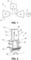
- Fig. 1 shows a schematic diagram of a gas turbine engine 10 as may be described herein.
- the gas turbine engine 10 may include a compressor 15.
- the compressor 15 compresses an incoming flow of air 20.
- the compressor 15 delivers the compressed flow of air 20 to a number of combustor cans 25.
- the combustor cans 25 mix the compressed flow of air 20 with a pressurized flow of fuel 30 and ignite the mixture to create a flow of hot combustion gases 35.
- the gas turbine engine 10 may include any number of combustor cans 25 positioned in a circumferential array and the like.
- the combustor 25 may be an annular combustor.
- the flow of combustion gases 35 is in turn delivered to a turbine 40.
- the flow of combustion gases 35 drives the turbine 40 to produce mechanical work.
- the mechanical work produced in the turbine 40 drives the compressor 15 via a rotor shaft 45.
- the turbine 40 and the rotor shaft 45 also may drive an external load 50 such as an electrical generator and the like.
- the gas turbine engine 10 may use natural gas, hydrogen gas, various types of syngas, liquid fuels, and/or other types of fuels and blends thereof.
- the gas turbine engine 10 may be any one of a number of different gas turbine engines offered by General Electric Company of Schenectady, New York, including, but not limited to, those such as a 7-series or a 9-series heavy duty gas turbine engine and the like.
- the gas turbine engine 10 may be part of a simple cycle or a combined cycle power generation system or other types of generation systems.
- the gas turbine engine 10 may have different configurations and may use other types of components. Other types of gas turbine engines also may be used herein. Multiple gas turbine engines, other types of turbines, and other types of power generation equipment also may be used herein together.
- Fig. 2 shows an example of a turbine component 55 that may be used with the turbine 40.
- the turbine component 55 may be a turbine blade 56.
- the turbine blade 56 includes an airfoil 60, a shank portion 65, and a platform 70 disposed between the airfoil 60 and the shank portion 65.
- the airfoil 60 generally extends radially outward from the platform 70 and includes a leading edge 72 and a trailing edge 74.
- the airfoil 60 also may include a concave wall defining a pressure side 76 and a convex wall defining a suction side 78.
- the platform 70 may be substantially horizontal and planar. The platform 70 may be exposed to the flow of the hot combustion gases 35.
- the shank portion 65 may include a shank cavity 80 therein.
- the shank portion 65 also may include one or more angel wings 82 and a root structure 84, such as a dovetail and the like.
- the root structure 84 may be configured to secure the turbine blade 56 to a rotor disk.
- the turbine blade 56 may include one or more cooling circuits 86 extending therethrough for flowing a cooling medium, such as air from the compressor 15 or from another source.
- the cooling circuits 86 and the cooling medium may circulate at least through portions of the airfoil 60, the shank portion 65, and the platform 70 in any order, direction, or route to form a cooling medium flow path.
- Many different types of turbine components 55 may be used herein.
- the turbine blade 56 defined herein is for the purpose of example only. Other components and other configurations also may be used herein.
- Additive manufacturing techniques to create a turbine component casting mold generally include a number of process steps. These steps may include mold design via a CAD process, printing the mold via a ceramic slurry, preparing the mold via evacuation, cleaning, and firing the mold. These steps, however, may create stress concentrations and other faults in the mold. This is particularly true during the firing step that may place a significant amount of stress on the ceramic components and may lead to cracking and dimensional nonconformance.
- Fig. 3 shows an existing airfoil fired mold 88 created by an additive manufacturing process. As is shown, the airfoil mold 88 has collapsed during the firing step. This collapse is considered a flaw 90 in the overall mold design. Another flaw 96 is a crack that forms in any wall of the mold 88.
- Fig. 4 shows a turbine component fired mold 100 made from a ceramic 110 from slurry in an additive manufacturing process.
- Additive manufacturing processes can take advantage of optimization of mold external features, for example, to improve mold strength, or to impart microstructural advancements in any location during the mold making process by adding external reinforcement features 120 to a component body 125.
- the external reinforcement features 120 of the turbine component fired mold 100 may include external ribbing 130 to an airfoil portion 140 of the turbine component mold 100.
- the external ribbing 130 may extend in the vertical or horizontal directions or in any convenient direction.
- the external ribbing 130 may be placed on the surface in any shape/form calculated by structural methods and validated by experience. Likewise, the size and shape of the external ribbing 130 may vary upon application.
- the addition of the external ribbing 130 to the turbine component mold 100 allows the turbine component mold 100 to maintain the desired dimensional conformance during the firing step and the like.
- the external ribbing 130 and other types of external reinforcement features 120 help distribute stresses more evenly during 3D printing and post-print processes so as to improve the overall stiffness and strength of the turbine component mold 100.
- the external surface of a mold has been largely ignored, i.e., due to multiple shell dips and uniformly thick shells.
- TPO topological optimization
- topology optimization is a mathematical method that optimizes material layout within a given design space, for a given set of loads, boundary conditions and constraints with the goal of maximizing the performance of the system. Topology optimization is different from shape optimization and sizing optimization in the sense that the design may attain any shape within the design space, instead of dealing with predefined configurations.
- the conventional topology optimization formulation uses a finite element method (FEM) to evaluate the design performance. A number of different TPO systems are currently available.
- FEM finite element method
- Figs. 5 and 6 show a further example of a turbine component fired mold 100.
- a turbine blade mold 150 The turbine blade mold 150 may be a combined core and shell 155 and the like.
- a shank portion 160 of the turbine blade mold 100 has the external ribbing 130.
- both the shank portion 160 and the airfoil portion 140 have the external ribbing 130.
- the shank portion 160 and/or the base portion 170 also may include a number of gussets 180 formed therein.
- the use of the external ribbing 130 may greatly stiffen the airfoil portion 140 of the turbine blade mold 150 so as to tightly control deformation therein.
- the use of the gussets 180 adds rigidity to the shank portion 160 and base portion 170 for optimal upright positioning of the turbine component mold 100 during firing and other process steps.
- topological optimization may include reinforced corners and edges 190. Such corners and edges 190 typically may be high-stress areas in the turbine component mold 100. Topological optimization may reinforce these regions by adding material so as to enhance resistance to deformation and cracking. Topological optimization also may smooth out stress concentration points in the overall geometry of the turbine component mold 100. By redistributing the ceramic slurry material 110, the turbine component mold 100 may become more resilient and less susceptible to failure in critical areas.
- the topological optimization process may identify load bearing areas 200 that bear the most stress (per casting geometry and melt characteristics) during the casting process. These load bearing areas 200 may be strengthened and optimized to withstand higher pressures and maintain shape integrity by creeping less during the casting process.
- fillets 210 i.e., rounded corners or edges
- Topological optimization may optimize the sizes and shapes of the fillets 210 to minimize stress concentrations and enhance overall mold strength.
- Topological optimization may help identify areas where material thickness 220 may be increased or reduced. These changes enable the turbine component mold 100 to be more efficient in material usage while maintaining or even improving overall structural integrity.
- the optimization process may be used to tailor the external structure of the turbine component mold 100 to provide anisotropic properties, i.e., different mechanical properties along different directions. Such properties may be beneficial for applications where directional strength is crucial.
- the specific features and designs resulting from topological optimization will vary based on the intended application, load conditions, and manufacturing constraints. The optimization process takes these factors into account to arrive at the most suitable and efficient design for the external reinforcement features 120 and the turbine component mold 100.
- the use of the external reinforcement features 120 on the turbine component mold 100 thus speeds and improves the overall casting process.
- the process steps of CAD design, printing, firing, casting, and finishing are all simplified and made more efficient.
- the combination of additive manufacturing and local optimization provides needed rigidity those areas of the areas of the turbine component mold 100 that may tend to crack or deform.
- the external reinforcement features 120 allows the turbine component mold 100 to stand stably in any firing orientation.
- the overall design of the turbine component mold 100 may be quickly changed to take into account specific applications and/or customizable designs.
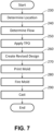
- Fig. 7 is a flowchart showing exemplary steps in a method of maximizing the design of the turbine component mold 100 to minimize productions flaws.
- the portion in the turbine component mold 100 with a flaw 90 is determined. For example, cracking in the airfoil portion 140.
- the nature of the flaw 90 is determined. For example, cracking.
- topological optimization processes may be applied to create external reinforcement features 120 to resolve the flaw 90.
- the external reinforcement features 120 may be the external ribbing 130 or other structures to reduce stress concentrations and accommodate load bearing areas as well as changes in material thickness.
- the design of the revised or improved turbine component mold 100 may be created in a CAD process and the like.
- the improved turbine component mold 100 may be created in an additive manufacturing process.
- the turbine component mold 100 may be fired.
- the turbine component mold 100 may be used for casting. Other and different processing steps may be used herein.
Landscapes
- Engineering & Computer Science (AREA)
- Mechanical Engineering (AREA)
- Chemical & Material Sciences (AREA)
- Manufacturing & Machinery (AREA)
- Materials Engineering (AREA)
- Ceramic Engineering (AREA)
- Turbine Rotor Nozzle Sealing (AREA)
- Molds, Cores, And Manufacturing Methods Thereof (AREA)
- Mold Materials And Core Materials (AREA)
- Producing Shaped Articles From Materials (AREA)
Abstract
Description
- The present application and the resultant patent relate generally to cast components, such as cast parts, cast components, cast gas parts, and the like, and more particularly relate to improved methods and systems for integrated fixturing of strengthened direct print molds to create castings of components in a highly efficient and accurate manner.
- A gas turbine engine conventionally includes a compressor for compressing ambient air and a number of combustors for mixing the flow of air with a flow of fuel to generate hot combustion gases. A turbine receives the flow of hot combustion gases and extracts energy therefrom for powering the compressor and for producing output power for an external load such as an electrical generator and the like. The hot gas path components of the gas turbine engine, such as turbine airfoils, traditionally were manufactured using an investment casting process. In such a process, molten metal alloy is introduced into a mold cavity defined between a shell and a core and allowed to solidify so as to form a completed casting. Depending on the application, the turbine components may be required to withstand thermal stresses due to high temperatures, centrifugal forces, and large temperature fluctuations. Accordingly, the turbine components may include internal cooling passages as well as other types of complex geometries.
- Conventional mold techniques for manufacturing turbine components may be time-consuming and/or may limit the resolution of the mold and/or the core. Moreover, the shell formed after slurry dips may limit heat transfer. By contrast, additive manufacturing techniques and 3-D printing allows the first molds to be manufactured in a fast and efficient manner. Manufacturing highly complex shapes and/or the rigors of the multiple process steps between printing and casting, however, may cause stress features that result in cracking or deformation of the additively manufactured mold. Previous attempts to strengthen such molds have focused on developing mold compositions and firing processes to slow down burnout schedules. Similarly other attempts have used designs with internal recesses with different types of inserts. The use of such inserts, however, adds time and cost to the manufacturing process.
- The present application and the resultant patent provide a method of optimizing strength in an improved mold for a cast component. The method may include the steps of evaluating a flaw in an existing mold, adding external reinforcement features to a design of the improved mold, manufacturing the improved mold in an additive manufacturing process, and casting the cast component in the improved mold.
- The present application and the resultant patent further may provide a mold for a cast component. The mold may include a component body of a ceramic material made from an additive manufacturing process and one or more external reinforcement features manufactured in the component body.
- These and other features and improvements of this application and the resultant patent will become apparent to one of ordinary skill in the art upon review of the following detailed description when taken in conjunction with the several drawings and the appended claims.
-
-
Fig. 1 is a schematic diagram of a gas turbine engine including a compressor, a combustor, a turbine, and an external load. -
Fig. 2 is a perspective view of a turbine blade. -
Fig. 3 is a perspective view of an example turbine component fired mold with a flaw. -
Fig. 4 is a perspective view of an example turbine component fired mold with external reinforcement features. -
Fig. 5 is a perspective view of a turbine component mold with additional external reinforcement features. -
Fig. 6 is a perspective view of a turbine component mold with additional external reinforcement features. -
Fig. 7 is a flow chart of exemplary process steps in creating a turbine component mold with external reinforcement features. - Referring now to the drawings, in which like numerals refer to like elements throughout the several views,
Fig. 1 shows a schematic diagram of agas turbine engine 10 as may be described herein. Thegas turbine engine 10 may include acompressor 15. Thecompressor 15 compresses an incoming flow ofair 20. Thecompressor 15 delivers the compressed flow ofair 20 to a number ofcombustor cans 25. The combustor cans 25 mix the compressed flow ofair 20 with a pressurized flow offuel 30 and ignite the mixture to create a flow ofhot combustion gases 35. Although only a single combustor can 25 is shown, thegas turbine engine 10 may include any number ofcombustor cans 25 positioned in a circumferential array and the like. Alternatively, thecombustor 25 may be an annular combustor. The flow ofcombustion gases 35 is in turn delivered to aturbine 40. The flow ofcombustion gases 35 drives theturbine 40 to produce mechanical work. The mechanical work produced in theturbine 40 drives thecompressor 15 via arotor shaft 45. Theturbine 40 and therotor shaft 45 also may drive anexternal load 50 such as an electrical generator and the like. - The
gas turbine engine 10 may use natural gas, hydrogen gas, various types of syngas, liquid fuels, and/or other types of fuels and blends thereof. Thegas turbine engine 10 may be any one of a number of different gas turbine engines offered by General Electric Company of Schenectady, New York, including, but not limited to, those such as a 7-series or a 9-series heavy duty gas turbine engine and the like. Thegas turbine engine 10 may be part of a simple cycle or a combined cycle power generation system or other types of generation systems. Thegas turbine engine 10 may have different configurations and may use other types of components. Other types of gas turbine engines also may be used herein. Multiple gas turbine engines, other types of turbines, and other types of power generation equipment also may be used herein together. -
Fig. 2 shows an example of aturbine component 55 that may be used with theturbine 40. In this example, theturbine component 55 may be aturbine blade 56. Generally described, theturbine blade 56 includes anairfoil 60, ashank portion 65, and aplatform 70 disposed between theairfoil 60 and theshank portion 65. Theairfoil 60 generally extends radially outward from theplatform 70 and includes a leadingedge 72 and atrailing edge 74. Theairfoil 60 also may include a concave wall defining apressure side 76 and a convex wall defining asuction side 78. Theplatform 70 may be substantially horizontal and planar. Theplatform 70 may be exposed to the flow of thehot combustion gases 35. Theshank portion 65 may include ashank cavity 80 therein. Theshank portion 65 also may include one ormore angel wings 82 and aroot structure 84, such as a dovetail and the like. Theroot structure 84 may be configured to secure theturbine blade 56 to a rotor disk. - The
turbine blade 56 may include one ormore cooling circuits 86 extending therethrough for flowing a cooling medium, such as air from thecompressor 15 or from another source. Thecooling circuits 86 and the cooling medium may circulate at least through portions of theairfoil 60, theshank portion 65, and theplatform 70 in any order, direction, or route to form a cooling medium flow path. Many different types ofturbine components 55 may be used herein. Theturbine blade 56 defined herein is for the purpose of example only. Other components and other configurations also may be used herein. - Additive manufacturing techniques to create a turbine component casting mold generally include a number of process steps. These steps may include mold design via a CAD process, printing the mold via a ceramic slurry, preparing the mold via evacuation, cleaning, and firing the mold. These steps, however, may create stress concentrations and other faults in the mold. This is particularly true during the firing step that may place a significant amount of stress on the ceramic components and may lead to cracking and dimensional nonconformance. For example,
Fig. 3 shows an existing airfoil firedmold 88 created by an additive manufacturing process. As is shown, theairfoil mold 88 has collapsed during the firing step. This collapse is considered aflaw 90 in the overall mold design. Another flaw 96 is a crack that forms in any wall of themold 88. -
Fig. 4 shows a turbine component firedmold 100 made from a ceramic 110 from slurry in an additive manufacturing process. Additive manufacturing processes can take advantage of optimization of mold external features, for example, to improve mold strength, or to impart microstructural advancements in any location during the mold making process by adding external reinforcement features 120 to acomponent body 125. For example, the external reinforcement features 120 of the turbine component firedmold 100 may includeexternal ribbing 130 to anairfoil portion 140 of theturbine component mold 100. Theexternal ribbing 130 may extend in the vertical or horizontal directions or in any convenient direction. Theexternal ribbing 130 may be placed on the surface in any shape/form calculated by structural methods and validated by experience. Likewise, the size and shape of theexternal ribbing 130 may vary upon application. The addition of theexternal ribbing 130 to theturbine component mold 100 allows theturbine component mold 100 to maintain the desired dimensional conformance during the firing step and the like. Theexternal ribbing 130 and other types of external reinforcement features 120 help distribute stresses more evenly during 3D printing and post-print processes so as to improve the overall stiffness and strength of theturbine component mold 100. Traditionally, the external surface of a mold has been largely ignored, i.e., due to multiple shell dips and uniformly thick shells. - These external reinforcement features 120 may be designed into the CAD programing for mold printing by the methods and principles of, for example, topological optimization (TPO) used in various engineering disciplines and computational mechanics. TPO is a process used to optimize the distribution of material within a given design space (e.g., 3D casting mold) to achieve specific performance objectives (e.g., strengthening shell externals for handling ease, minimizing internal cracking in fired microstructure, and the like).
- Specifically, topology optimization is a mathematical method that optimizes material layout within a given design space, for a given set of loads, boundary conditions and constraints with the goal of maximizing the performance of the system. Topology optimization is different from shape optimization and sizing optimization in the sense that the design may attain any shape within the design space, instead of dealing with predefined configurations. The conventional topology optimization formulation uses a finite element method (FEM) to evaluate the design performance. A number of different TPO systems are currently available.
-
Figs. 5 and 6 show a further example of a turbine component firedmold 100. In these examples, a turbine blade mold 150. The turbine blade mold 150 may be a combined core andshell 155 and the like. In the example ofFig. 5 , only ashank portion 160 of theturbine blade mold 100 has theexternal ribbing 130. In the example ofFig. 6 , both theshank portion 160 and theairfoil portion 140 have theexternal ribbing 130. Further, theshank portion 160 and/or the base portion 170 (the pour cup region) also may include a number ofgussets 180 formed therein. The use of theexternal ribbing 130 may greatly stiffen theairfoil portion 140 of the turbine blade mold 150 so as to tightly control deformation therein. Likewise, the use of thegussets 180 adds rigidity to theshank portion 160 andbase portion 170 for optimal upright positioning of theturbine component mold 100 during firing and other process steps. - Other areas of topological optimization may include reinforced corners and edges 190. Such corners and
edges 190 typically may be high-stress areas in theturbine component mold 100. Topological optimization may reinforce these regions by adding material so as to enhance resistance to deformation and cracking. Topological optimization also may smooth out stress concentration points in the overall geometry of theturbine component mold 100. By redistributing theceramic slurry material 110, theturbine component mold 100 may become more resilient and less susceptible to failure in critical areas. - Similarly, the topological optimization process may identify
load bearing areas 200 that bear the most stress (per casting geometry and melt characteristics) during the casting process. Theseload bearing areas 200 may be strengthened and optimized to withstand higher pressures and maintain shape integrity by creeping less during the casting process. Likewise, fillets 210 (i.e., rounded corners or edges) may be used to smoothen the transitions between different surfaces in theturbine component mold 100. Topological optimization may optimize the sizes and shapes of thefillets 210 to minimize stress concentrations and enhance overall mold strength. - Other concerns may include the
overall material thickness 220. Topological optimization may help identify areas wherematerial thickness 220 may be increased or reduced. These changes enable theturbine component mold 100 to be more efficient in material usage while maintaining or even improving overall structural integrity. Likewise, the optimization process may be used to tailor the external structure of theturbine component mold 100 to provide anisotropic properties, i.e., different mechanical properties along different directions. Such properties may be beneficial for applications where directional strength is crucial. The specific features and designs resulting from topological optimization will vary based on the intended application, load conditions, and manufacturing constraints. The optimization process takes these factors into account to arrive at the most suitable and efficient design for the external reinforcement features 120 and theturbine component mold 100. - The use of the external reinforcement features 120 on the
turbine component mold 100 thus speeds and improves the overall casting process. The process steps of CAD design, printing, firing, casting, and finishing are all simplified and made more efficient. The combination of additive manufacturing and local optimization provides needed rigidity those areas of the areas of theturbine component mold 100 that may tend to crack or deform. Likewise, the external reinforcement features 120 allows theturbine component mold 100 to stand stably in any firing orientation. Moreover, the overall design of theturbine component mold 100 may be quickly changed to take into account specific applications and/or customizable designs. -
Fig. 7 is a flowchart showing exemplary steps in a method of maximizing the design of theturbine component mold 100 to minimize productions flaws. Instep 230, the portion in theturbine component mold 100 with aflaw 90 is determined. For example, cracking in theairfoil portion 140. Instep 240, the nature of theflaw 90 is determined. For example, cracking. Instep 250, topological optimization processes may be applied to create external reinforcement features 120 to resolve theflaw 90. For example, the external reinforcement features 120 may be theexternal ribbing 130 or other structures to reduce stress concentrations and accommodate load bearing areas as well as changes in material thickness. Instep 260, the design of the revised or improvedturbine component mold 100 may be created in a CAD process and the like. Instep 270, the improvedturbine component mold 100 may be created in an additive manufacturing process. Instep 280, theturbine component mold 100 may be fired. Instep 290, theturbine component mold 100 may be used for casting. Other and different processing steps may be used herein. - It should be apparent that the foregoing relates only to certain embodiments of the present application and resultant patent. Numerous changes and modifications may be made herein by one of ordinary skill in the art without departing from the general spirit and scope of the invention as defined by the following claims and the equivalents thereof.
- Further aspects of the invention are provided by the subject matter of the following clauses:
- 1. A method of optimizing strength in an improved mold for a cast component, comprising: evaluating a flaw in an existing mold; adding external reinforcement features to a design of the improved mold; manufacturing the improved mold in an additive manufacturing process; and casting the cast component in the improved mold.
- 2. The method of any preceding clause, wherein the step of adding external reinforcement features to a design of the improved mold comprises adding external ribbing to a section of the improved mold.
- 3. The method of any preceding clause, wherein the cast component is a turbine component, and the step of adding external reinforcement features to a design of the improved mold comprises adding external ribbing to at least one of an airfoil portion and a shank portion of the improved mold.
- 4. The method of any preceding clause, wherein the step of adding external reinforcement features to a design of the improved mold comprises adding gussets to a base portion and/or a shank portion of the improved mold.
- 5. The method of any preceding clause, wherein the cast component is a turbine component, and the step of adding external reinforcement features to a design of the improved mold comprises adding a fillet about an airfoil portion of the improved mold.
- 6. The method of any preceding clause, wherein the step of adding external reinforcement features to a design of the improved mold comprises adding external reinforcement features to a load bearing area of the improved mold.
- 7. The method of any preceding clause, wherein the step of adding external reinforcement features to a design of the improved mold comprises a topological optimization process.
- 8. The method of any preceding clause, wherein the topological optimization process reduces stress concentrations in the improved mold as compared to the existing mold.
- 9. The method of any preceding clause, wherein the step of manufacturing the improved mold in an additive manufacturing process comprises using a ceramic material.
- 10. The method of any preceding clause, wherein the topological optimization process comprises redistributing the ceramic material in the improved mold.
- 11. The method of c any preceding clause, wherein the topological optimization process comprises changing a thickness of the ceramic material in the improved mold.
- 12. The method of any preceding clause, further comprising firing the improved mold.
- 13. The method of any preceding clause, wherein the step of adding external reinforcement features to a design of the improved mold comprises a Computer Aided Design process.
- 14. The method of any preceding clause, wherein the improved mold comprises a combined core and shell.
- 15. A mold for a cast component, comprising: a component body; wherein the component body comprises a ceramic material made from an additive manufacturing process; and one or more external reinforcement features manufactured in the component body.
- 16. The mold for a cast component of any preceding clause, wherein the one or more external reinforcement features comprise external ribbing.
- 17. The mold for a cast component of any preceding clause, wherein the cast component is a turbine component, and the component body comprises at least one of an airfoil portion and a shank portion and the one or more external reinforcement features comprise external ribbing.
- 18. The mold for a cast component of any preceding clause, wherein the one or more external reinforcement features comprise gussets.
- 19. The mold for a cast component of any preceding clause, wherein the one or more external reinforcement features comprise fillets.
- 20. The mold for a cast component of any preceding clause, wherein the one or more external reinforcement features comprise external ribbing, gussets, and/or fillets.
Claims (15)
- A method of optimizing strength in an improved mold (100) for a cast component (55), comprising:evaluating a flaw (90) in an existing mold (88);adding external reinforcement features (120) to a design of the improved mold (100);manufacturing the improved mold (100) in an additive manufacturing process; andcasting the cast component (55) in the improved mold (100).
- The method of claim 1, wherein the step of adding external reinforcement features (120) to a design of the improved mold (100) comprises adding external ribbing (130) to a section (140) of the improved mold (100).
- The method of claim 1, wherein the cast component is a turbine component (55), and the step of adding external reinforcement features (120) to a design of the improved mold (100) comprises adding external ribbing (130) to at least one of an airfoil portion (140) and shank portion (160) of the improved mold (100).
- The method of claim 1, wherein the step of adding external reinforcement features (120) to a design of the improved mold (100) comprises adding gussets (180) to a base portion (170) and/or a shank portion (160) of the improved mold (100).
- The method of claim 1, wherein the cast component is a turbine component (55), and the step of adding external reinforcement features (120) to a design of the improved mold (100) comprises adding a fillet (210) about an airfoil portion (140) of the improved mold (100).
- The method of claim 1, wherein the step of adding external reinforcement features (120) to a design of the improved mold (100) comprises adding external reinforcement features (120) to a load bearing area (200) of the improved mold (100).
- The method of claim 1, wherein the step of adding external reinforcement features (120) to a design of the improved mold (100) comprises a topological optimization process.
- The method of claim 7, wherein the topological optimization process reduces stress concentrations in the improved mold (100) as compared to the existing mold (88).
- The method of claim 7, wherein the step of manufacturing the improved mold (100) in an additive manufacturing process comprises using a ceramic material (110).
- The method of claim 9, wherein the topological optimization process comprises redistributing the ceramic material (110) in the improved mold (100).
- The method of claim 10, wherein the topological optimization process comprises changing a thickness of the ceramic material (110) in the improved mold (100).
- The method of claim 1, further comprising firing the improved mold (100).
- The method of claim 1, wherein the improved mold (100) comprises a combined core and shell (155).
- A mold (100) for a cast component (55), comprising:
a component body (125);wherein the component body (125) comprises a ceramic material (110) made from an additive manufacturing process; andone or more external reinforcement features (120) manufactured in the component body (125). - The mold for a cast component of claim 14, wherein the one or more external reinforcement features (120) comprise external ribbing (130), gussets (180), and/or fillets (210).
Applications Claiming Priority (1)
| Application Number | Priority Date | Filing Date | Title |
|---|---|---|---|
| US18/468,148 US12343787B2 (en) | 2023-09-15 | 2023-09-15 | Method for integrated fixturing of direct print molds for cast components |
Publications (2)
| Publication Number | Publication Date |
|---|---|
| EP4523812A2 true EP4523812A2 (en) | 2025-03-19 |
| EP4523812A3 EP4523812A3 (en) | 2025-11-19 |
Family
ID=92503897
Family Applications (1)
| Application Number | Title | Priority Date | Filing Date |
|---|---|---|---|
| EP24195560.8A Pending EP4523812A3 (en) | 2023-09-15 | 2024-08-21 | Method for integrated fixturing of direct print molds for cast components |
Country Status (5)
| Country | Link |
|---|---|
| US (2) | US12343787B2 (en) |
| EP (1) | EP4523812A3 (en) |
| JP (1) | JP2025043290A (en) |
| KR (1) | KR20250040517A (en) |
| CN (1) | CN119681203A (en) |
Citations (1)
| Publication number | Priority date | Publication date | Assignee | Title |
|---|---|---|---|---|
| US10493523B1 (en) * | 2016-02-04 | 2019-12-03 | Williams International Co., L.L.C. | Method of producing a cast component |
Family Cites Families (11)
| Publication number | Priority date | Publication date | Assignee | Title |
|---|---|---|---|---|
| US20130220570A1 (en) * | 2012-02-29 | 2013-08-29 | Ford Motor Company | Additive fabrication technologies for creating molds for die components |
| US9498819B2 (en) * | 2013-03-14 | 2016-11-22 | Hitchiner Manufacturing Co., Inc. | Refractory mold and method of making |
| US9987679B2 (en) * | 2013-10-07 | 2018-06-05 | United Technologies Corporation | Rapid tooling insert manufacture |
| US11192172B2 (en) * | 2017-06-28 | 2021-12-07 | General Electric Company | Additively manufactured interlocking casting core structure with ceramic shell |
| US11014153B2 (en) * | 2017-10-23 | 2021-05-25 | General Electric Company | Method for seeding a mold |
| US20190111472A1 (en) | 2017-10-18 | 2019-04-18 | General Electric Company | High temperature engineering stiffness core-shell mold for casting |
| WO2021015074A1 (en) * | 2019-07-23 | 2021-01-28 | 三菱電機株式会社 | Casting mold, and method for manufacturing casting mold |
| US12168309B2 (en) | 2021-05-11 | 2024-12-17 | General Electric Company | Methods for casting a component via a unitary core-shell mold |
| CN114178484B (en) * | 2021-11-30 | 2023-03-21 | 清华大学 | Integrated casting method of hollow turbine blade |
| US20230311199A1 (en) * | 2022-04-05 | 2023-10-05 | General Electric Company | Casting mold |
| CN116000243A (en) * | 2023-01-05 | 2023-04-25 | 东风柳州汽车有限公司 | Method for manufacturing aluminum alloy part |
-
2023
- 2023-09-15 US US18/468,148 patent/US12343787B2/en active Active
-
2024
- 2024-08-20 CN CN202411140642.1A patent/CN119681203A/en active Pending
- 2024-08-21 EP EP24195560.8A patent/EP4523812A3/en active Pending
- 2024-08-29 JP JP2024147765A patent/JP2025043290A/en active Pending
- 2024-09-10 KR KR1020240123000A patent/KR20250040517A/en active Pending
-
2025
- 2025-04-24 US US19/188,105 patent/US20250249499A1/en active Pending
Patent Citations (1)
| Publication number | Priority date | Publication date | Assignee | Title |
|---|---|---|---|---|
| US10493523B1 (en) * | 2016-02-04 | 2019-12-03 | Williams International Co., L.L.C. | Method of producing a cast component |
Non-Patent Citations (1)
| Title |
|---|
| CHEN SHUANG ET AL: "Alumina-based ceramic mold with integral core and shell for hollow turbine blades fabricated by laser powder bed fusion", ADDITIVE MANUFACTURING ELSEVIER, NL, vol. 58, 19 July 2022 (2022-07-19), XP087158850, ISSN: 2214-8604, [retrieved on 20220719], DOI: 10.1016/J.ADDMA.2022.103046 * |
Also Published As
| Publication number | Publication date |
|---|---|
| JP2025043290A (en) | 2025-03-28 |
| US12343787B2 (en) | 2025-07-01 |
| US20250249499A1 (en) | 2025-08-07 |
| KR20250040517A (en) | 2025-03-24 |
| EP4523812A3 (en) | 2025-11-19 |
| US20250091118A1 (en) | 2025-03-20 |
| CN119681203A (en) | 2025-03-25 |
Similar Documents
| Publication | Publication Date | Title |
|---|---|---|
| CN112512732B (en) | Support structures and methods for additive manufacturing of impellers | |
| CN1916372B (en) | Methods and apparatus for reducing vibrations induced to airfoils | |
| US8506256B1 (en) | Thin walled turbine blade and process for making the blade | |
| CN106337696A (en) | System and method for turbine blade repair | |
| EP3429778B1 (en) | Method of manufacturing advanced features in a core for casting | |
| US9797258B2 (en) | Turbine bucket including cooling passage with turn | |
| JP2014139428A (en) | Method of making surface cooling channels on component using lithographic molding techniques | |
| EP2567070B1 (en) | Light weight shroud fin for a rotor blade | |
| JP2012026448A (en) | Components with bonded edges | |
| JP6877969B2 (en) | How to repair deep tip cracks | |
| JP7023628B2 (en) | Turbo machine components with collision heat transfer function, related turbo machines and storage media | |
| EP4031750B1 (en) | Integrated nozzle and diaphragm with optimized internal vane wall thickness | |
| US11541452B2 (en) | Manufacturing method and tooling for ceramic cores | |
| US10927693B2 (en) | Unitary body turbine shroud for turbine systems | |
| EP4088835B1 (en) | Methods for casting a component via a unitary core-shell mold | |
| US12343787B2 (en) | Method for integrated fixturing of direct print molds for cast components | |
| US20200248558A1 (en) | Unitary body turbine shrouds including internal cooling passages | |
| EP3660270B1 (en) | Cooled airfoil including plurality of nozzles and venturi | |
| EP3181265A1 (en) | Method and assembly for forming components having internal passages using a lattice structure | |
| Musgrove et al. | Design and Testing of an Internally-Cooled Radial Turbine With High Tip Speed | |
| EP3433036B1 (en) | Method of manufacturing a hybridized core with protruding cast in cooling features for investment casting |
Legal Events
| Date | Code | Title | Description |
|---|---|---|---|
| PUAI | Public reference made under article 153(3) epc to a published international application that has entered the european phase |
Free format text: ORIGINAL CODE: 0009012 |
|
| STAA | Information on the status of an ep patent application or granted ep patent |
Free format text: STATUS: THE APPLICATION HAS BEEN PUBLISHED |
|
| AK | Designated contracting states |
Kind code of ref document: A2 Designated state(s): AL AT BE BG CH CY CZ DE DK EE ES FI FR GB GR HR HU IE IS IT LI LT LU LV MC ME MK MT NL NO PL PT RO RS SE SI SK SM TR |
|
| RAP3 | Party data changed (applicant data changed or rights of an application transferred) |
Owner name: GE VERNOVA TECHNOLOGY GMBH |
|
| PUAL | Search report despatched |
Free format text: ORIGINAL CODE: 0009013 |
|
| AK | Designated contracting states |
Kind code of ref document: A3 Designated state(s): AL AT BE BG CH CY CZ DE DK EE ES FI FR GB GR HR HU IE IS IT LI LT LU LV MC ME MK MT NL NO PL PT RO RS SE SI SK SM TR |
|
| RIC1 | Information provided on ipc code assigned before grant |
Ipc: B22C 9/04 20060101AFI20251010BHEP Ipc: B22C 9/10 20060101ALI20251010BHEP Ipc: B22C 9/12 20060101ALI20251010BHEP Ipc: B22C 9/24 20060101ALI20251010BHEP Ipc: B33Y 80/00 20150101ALI20251010BHEP Ipc: B22C 9/02 20060101ALI20251010BHEP |
|
| STAA | Information on the status of an ep patent application or granted ep patent |
Free format text: STATUS: REQUEST FOR EXAMINATION WAS MADE |
|
| 17P | Request for examination filed |
Effective date: 20260206 |
|
| STAA | Information on the status of an ep patent application or granted ep patent |
Free format text: STATUS: EXAMINATION IS IN PROGRESS |
|
| 17Q | First examination report despatched |
Effective date: 20260618 |