EP4523799A1 - Coating die and coating device - Google Patents
Coating die and coating device Download PDFInfo
- Publication number
- EP4523799A1 EP4523799A1 EP23896206.2A EP23896206A EP4523799A1 EP 4523799 A1 EP4523799 A1 EP 4523799A1 EP 23896206 A EP23896206 A EP 23896206A EP 4523799 A1 EP4523799 A1 EP 4523799A1
- Authority
- EP
- European Patent Office
- Prior art keywords
- regulator
- die head
- discharge channel
- coating
- coating die
- Prior art date
- Legal status (The legal status is an assumption and is not a legal conclusion. Google has not performed a legal analysis and makes no representation as to the accuracy of the status listed.)
- Pending
Links
Images


Classifications
-
- B—PERFORMING OPERATIONS; TRANSPORTING
- B05—SPRAYING OR ATOMISING IN GENERAL; APPLYING FLUENT MATERIALS TO SURFACES, IN GENERAL
- B05C—APPARATUS FOR APPLYING FLUENT MATERIALS TO SURFACES, IN GENERAL
- B05C5/00—Apparatus in which liquid or other fluent material is projected, poured or allowed to flow on to the surface of the work
- B05C5/02—Apparatus in which liquid or other fluent material is projected, poured or allowed to flow on to the surface of the work the liquid or other fluent material being discharged through an outlet orifice by pressure, e.g. from an outlet device in contact or almost in contact, with the work
- B05C5/0254—Coating heads with slot-shaped outlet
- B05C5/0258—Coating heads with slot-shaped outlet flow controlled, e.g. by a valve
-
- B—PERFORMING OPERATIONS; TRANSPORTING
- B05—SPRAYING OR ATOMISING IN GENERAL; APPLYING FLUENT MATERIALS TO SURFACES, IN GENERAL
- B05C—APPARATUS FOR APPLYING FLUENT MATERIALS TO SURFACES, IN GENERAL
- B05C5/00—Apparatus in which liquid or other fluent material is projected, poured or allowed to flow on to the surface of the work
- B05C5/02—Apparatus in which liquid or other fluent material is projected, poured or allowed to flow on to the surface of the work the liquid or other fluent material being discharged through an outlet orifice by pressure, e.g. from an outlet device in contact or almost in contact, with the work
- B05C5/0254—Coating heads with slot-shaped outlet
-
- B—PERFORMING OPERATIONS; TRANSPORTING
- B05—SPRAYING OR ATOMISING IN GENERAL; APPLYING FLUENT MATERIALS TO SURFACES, IN GENERAL
- B05C—APPARATUS FOR APPLYING FLUENT MATERIALS TO SURFACES, IN GENERAL
- B05C5/00—Apparatus in which liquid or other fluent material is projected, poured or allowed to flow on to the surface of the work
- B05C5/02—Apparatus in which liquid or other fluent material is projected, poured or allowed to flow on to the surface of the work the liquid or other fluent material being discharged through an outlet orifice by pressure, e.g. from an outlet device in contact or almost in contact, with the work
- B05C5/0254—Coating heads with slot-shaped outlet
- B05C5/0262—Coating heads with slot-shaped outlet adjustable in width, i.e. having lips movable relative to each other in order to modify the slot width, e.g. to close it
-
- Y—GENERAL TAGGING OF NEW TECHNOLOGICAL DEVELOPMENTS; GENERAL TAGGING OF CROSS-SECTIONAL TECHNOLOGIES SPANNING OVER SEVERAL SECTIONS OF THE IPC; TECHNICAL SUBJECTS COVERED BY FORMER USPC CROSS-REFERENCE ART COLLECTIONS [XRACs] AND DIGESTS
- Y02—TECHNOLOGIES OR APPLICATIONS FOR MITIGATION OR ADAPTATION AGAINST CLIMATE CHANGE
- Y02E—REDUCTION OF GREENHOUSE GAS [GHG] EMISSIONS, RELATED TO ENERGY GENERATION, TRANSMISSION OR DISTRIBUTION
- Y02E60/00—Enabling technologies; Technologies with a potential or indirect contribution to GHG emissions mitigation
- Y02E60/10—Energy storage using batteries
Definitions
- the present application relates to the technical field of coating equipment, and in particular, to a coating die head and a piece of coating equipment that employs the coating die head.
- a coating die head of a piece of coating equipment in the related art is usually provided with a movable regulator to regulate a discharge flow rate of the coating die head, thereby realizing thickness regulation of the coating.
- a movable regulator to regulate a discharge flow rate of the coating die head, thereby realizing thickness regulation of the coating.
- a main purpose of the present application is to provide a coating die head to prevent generation of a stepped height difference during thickness regulation of a coating, so as to improve the coating effect of the coating equipment.
- the coating die head proposed by the present application includes:
- the coating die head further includes the at least two driving pieces and the regulator, so that a discharge flow rate of the discharge channel can be controlled by using the driving pieces to drive the regulator to move in the discharge channel, thereby realizing thickness regulation of a coating applied onto the substrate.
- the regulator in this solution is a flexible member.
- the regulator can well deform due to its flexibility, so that the regulator can form a smooth transitional shape in a region between the corresponding two adjacent driving pieces.
- the coating can also correspondingly form a smooth transitional shape in this region. In this way, generation of a stepped height difference is prevented during thickness regulation of the coating, thereby improving the coating effect of the coating equipment.
- the discharge channel includes a body section and an outlet section that are in communication with each other in sequence in the discharge direction of the discharge channel.
- a cross-sectional area of the outlet section of the discharge channel is less than a cross-sectional area of the body section of the discharge channel. At least a part of the regulator is movable within the outlet section.
- the outlet section is closer to a discharge port of the discharge channel than the body section, so after a flow rate of a slurry at a specific region is regulated by the regulator, the slurry can be quickly extruded out of the discharge port to form a coating with a required thickness, which is unlikely to be affected by flow-in of the slurry at other regions.
- the regulator extends along the first direction to form a long strip-shaped structure.
- This provides convenience for the regulator to have a relatively large regulation range, thereby improving the flexibility in thickness regulation of the coating.
- one regulator is provided, and in the first direction, a length of the regulator is the same as a length of the discharge channel.
- the regulator is provided in a quite small number, which can simplify the structure of the coating die head and thus improves the convenience in manufacturing of the coating die head. Moreover, there is only one regulator, which can better prevent the possibility of a thickness difference of the coating between adjacent regulators.
- the length of the regulator being the same as the length of the discharge channel can ensure that the regulator can still have a large regulation range when it is provided in a quite small number.
- At least two regulators are provided, the at least two regulators are distributed in the first direction, and each regulator is connected to at least two driving pieces.
- lengths of the at least two regulators are the same as the length of the discharge channel.
- the arrangement of the at least two regulators ensures that different regulators can be driven to move to realize flexible thickness regulation of different regions of the coating.
- the regulator is made of an anti-corrosion material.
- the regulator can be better prevented from corrosion of the slurry during coating, thereby helping to prolong the service life of the regulator.
- the regulator is a cubic structure.
- the regulator is regular in shape, thereby helping to improve the convenience in manufacturing thereof.
- the mounting groove can provide a mounting space for the regulator, thereby improving the convenience for arranging the regulator.
- the regulator can be provided with a relatively large volume, so that the strength of the regulator is enhanced, thereby providing convenience for the regulator to stably implement subsequent regulation work.
- the driving piece is in threaded connection with at least a part of a section of the communicating hole, and the driving piece is rotationally connected to the regulator.
- the driving piece is in threaded connection with the die head body, so that the driving piece is movable while rotating and thus drives the regulator connected thereto to move.
- the driving piece is a pure mechanical structure for driving the regulator and does not involve in a circuit, a gas circuit, and the like, thereby improving the safety of the coating die head during use.
- the regulator is provided with a clamping groove
- one end of the driving piece is provided with a clamping head
- the clamping head is clamped into the clamping groove and is rotatable in the clamping groove.
- the driving piece and the regulator are connected through clamping, so that the two can be detached, thereby helping to improve the convenience for maintaining or replacing the regulator and the driving piece.
- the present application further proposes a piece of coating equipment including the coating die head according to any one of the foregoing embodiments.
- connection may refer to a fixed connection, a detachable connection, or an integral connection, may refer to a mechanical connection or an electrical connection, and may refer to a direct connection, an indirect connection via an intermediate medium, an internal communication between two elements or an interaction between two elements, unless otherwise defined explicitly.
- fixation may refer to a fixed connection, a detachable connection, or an integral connection, may refer to a mechanical connection or an electrical connection, and may refer to a direct connection, an indirect connection via an intermediate medium, an internal communication between two elements or an interaction between two elements, unless otherwise defined explicitly.
- a piece of coating equipment is usually required to apply a prepared pasty viscous slurry onto a substrate.
- an edge effect is likely to occur at an edge position of the slurry that is applied, that is, thicknesses of edge regions at two sides of a coating formed by the slurry are greater than a thickness of a middle region.
- the uneven thickness of the coating on the substrate affects the performance such as capacity of the battery, and accordingly affects the subsequent use of the battery. Therefore, to ensure normal and stable subsequent use of the battery, it is necessary to control thinning of the slurry coating on the substrate during coating.
- a coating die head of a piece of coating equipment in the related art is usually provided with a movable regulator, so that the regulator is driven to move in a discharge channel to regulate a discharge flow rate of the coating die head, thereby realizing thickness regulation of the coating.
- a height difference between regulators when two adjacent driving pieces are driving the regulators for regulation so that the applied coating correspondingly generates a stepped height difference, thus affecting the coating effect of the coating equipment.
- a coating die head 100 includes a die head body 10, at least two driving pieces 30, and a regulator 50.
- the die head body 10 is provided with a discharge channel 11 in communication with an outside.
- the at least two driving pieces 30 are both arranged at the die head body 10 and distributed along a first direction, where the first direction is perpendicular to a discharge direction of the discharge channel 11.
- the regulator 50 is a flexible member, at least a part of the regulator 50 is arranged in the discharge channel 11 and connected to the at least two driving pieces 30, the driving pieces 30 are configured to drive the regulator 50 to move along a second direction in the discharge channel 11, and the second direction is perpendicular to the first direction and the discharge direction of the discharge channel 11.
- the die head body 10 can serve as a body structure of the coating die head 100, for forming the discharge channel 11, mounting the driving pieces 30 and the regulator 50, and the like.
- the discharge channel 11 includes a feed port and a discharge port 111.
- a to-be-applied slurry can enter the discharge channel 11 through the feeding port and is then extruded to a substrate through the discharge port 111, and then a coating process of the substrate is implemented.
- the feeding port may be a circular hole, a square hole, or the like. This is not specifically limited in the present application.
- the coated substrate generally has a large width, so the discharge port 111 can extend along a width direction of the substrate to form a long strip shape, that is, extending along the first direction.
- the die head body 10 is correspondingly a long strip-shaped structure extending in the first direction as well, thereby facilitating formation of the long strip-shaped discharge port 111 in a length direction thereof.
- the die head body 10 may be approximately a cubic structure.
- the driving pieces 30 may be configured to drive the regulator 50 to move, and the driving pieces 30 are distributed along the first direction, so that different driving pieces 30 can drive the corresponding regulator 50 to move, thereby realizing thickness regulation of the coating in different regions in the width direction.
- the driving of the driving pieces 30 to the regulator 50 may be implemented as described hereinafter: the driving pieces 30 are in threaded connection with the die head body 10 and thus is movable while rotating with respect to the die head body 10, thereby driving the regulator 50 connected to the driving pieces 30 to move.
- the driving pieces 30 may alternatively be cylinders, linear motors, or the like, so as to automatically drive the regulator 50.
- the regulator 50 may be arranged at an inner side of the die head body 10 or arranged at an outer side of the die head body 10, as long as the regulator 50 can be driven.
- the regulator 50 may be configured to regulate a discharge flow rate of the discharge channel 11.
- the regulator 50 when the regulator 50 is driven to move by the driving pieces 30, at least a part of the regulator 50 is located in the discharge channel 11. In this way, during movement of the regulator 50, a cross section of the discharge channel 11, through which the slurry can pass at this position, can be regulated. For example, when a regulator 50 is driven to move downwards by a corresponding driving piece 30, a cross section of the discharge channel 11 in a region corresponding to the regulator 50 is reduced, so that a flow rate of the slurry passing through this position can also be reduced, and ultimately the thickness of the coating in a coated region on the substrate corresponding to the regulator 50 can be reduced as well.
- the regulator 50 moves upwards, a cross section of the discharge channel 11 in a region corresponding to the regulator 50 is increased, so that a flow rate of the slurry passing through this position can also be increased, and ultimately the thickness of the coating in a coated region on the substrate corresponding to the regulator 50 can be increased as well. Therefore, the thickness of the coating on the corresponding region of the substrate can be regulated by driving the regulator 50 to move.
- the regulator 50 is a flexible member, so that when it is driven by each driving piece 30, each position of the regulator 50 can well deform and can form a smooth transitional shape at a position between the corresponding two adjacent driving pieces 30.
- the regulator 50 may be rubber, silicone, or another deformable object.
- a specific material of the regulator 50 is not limited in the present application, as long as the regulator 50 can be driven by the regulator 50 and can deform. Further, the regulator 50 may be partially arranged in the discharge channel 11. Certainly, the regulator 50 may be entirely arranged in the discharge channel 11. Alternatively, the regulator 50 is entirely arranged outside the discharge channel 11, as long as the regulator 50 can enter the discharge channel 11 to move so as to regulate the flow rate of the slurry when the regulator 50 is subsequently driven to move by a drive component. In addition, the regulator 50 may be a block structure, a plate structure, a column structure, or the like, as long as it can regulate the discharge flow rate of the discharge channel 11 during movement.
- a movement direction of the regulator 50 that is the second direction, can be perpendicular to the discharge direction of the discharge channel 11 and the first direction. This enables the regulator 50 to have a relatively short movement stroke, thereby helping to improve the convenience for driving and arranging it. Moreover, the regulator 50 in this case can well regulate a cross section of the discharge channel 11 for the slurry to pass through at this corresponding position even when the regulator 50 moves a smaller distance, thereby fully regulating the discharge flow rate of the discharge channel 11.
- the coating die head 100 During use of the coating die head 100 in this solution, the slurry can be extruded out of the discharge channel 11 to a to-be-coated substrate, and then the coating process of the substrate is implemented. Moreover, the coating die head 100 further includes the at least two driving pieces 30 and the regulator 50, so that a discharge flow rate of the discharge channel 11 can be controlled by using the driving pieces 30 to drive the regulator 50 to move in the discharge channel 11, thereby realizing thickness regulation of a coating applied onto the substrate. In addition, it is particularly important that the regulator 50 in this solution is a flexible member.
- the regulator 50 can well deform due to its flexibility, so that the regulator 50 can form a smooth transitional shape in a region between the corresponding two adjacent driving pieces 30.
- the coating can also correspondingly form a smooth transitional shape in this region. In this way, generation of a stepped height difference is prevented during thickness regulation of the coating, thereby improving the coating effect of the coating equipment.
- the discharge channel 11 includes a body section 113 and an outlet section 115 that communicate with each other in sequence in the discharge direction of the discharge channel 11.
- a cross-sectional area of the outlet section 115 is less than a cross-sectional area of the body section 113, and at least a part of the regulator 50 is movable within the outlet section 115.
- the regulator 50 extends along the first direction to form a long strip-shaped structure.
- the long strip-shaped structure means that the regulator 50 is a cuboid plate structure or columnar structure, and a length direction is formed in the first direction.
- the regulator 50 extends along the first direction, and the first direction corresponds to a width direction of the coating. Therefore, arranging the regulator 50 in a long strip shape allows the regulator 50 to have a relatively large regulation range, thereby helping to improve the flexibility in thickness regulation of the coating.
- the present application is not limited thereto.
- the regulator 50 may alternatively be a cube structure.
- one regulator 50 is provided, so that components of the coating die head 100 are significantly reduced. In this way, the structure of the coating die head 100 is simplified, thereby helping to improve the convenience in manufacturing thereof. Moreover, there is only one regulator 50, which can better prevent the possibility of a thickness difference of the coating between adjacent regulators 50.
- the length of the regulator 50 being the same as the length of the discharge channel 11 can ensure that the regulator 50 can still have a large regulation range when it is provided in a quite small number. Certainly, the present application is not limited thereto.
- At least two regulators 50 are provided as well; the at least two regulators 50 are distributed in the first direction; each regulator 50 is connected to at least two driving pieces 30; and in the first direction, the lengths of the at least two regulators 50 are the same as the length of the discharge channel 11.
- the arrangement of the at least two regulators 50 ensures that different regulators 50 can be driven to move to realize thickness regulation of different regions of the coating in the width direction of the coating, thereby helping to improve the flexibility in thickness regulation of the coating.
- the regulator 50 is made of an anti-corrosion material.
- the anti-corrosion material means that the regulator 50 can have acid and alkali resistance.
- the regulator 50 is made of an anti-corrosion material, so that the regulator 50 can be better prevented from corrosion of the slurry during coating, thereby helping to prolong the service life of the regulator 50.
- the regulator 50 may be made of anti-corrosion rubber, silicone, another anti-corrosion polymer material, or the like.
- the regulator 50 is a cubic structure.
- the cubic structure means that the regulator 50 may be a rectangular structure or a square structure.
- the regulator 50 is arranged as a cubic structure, so that the regulator 50 is regular in property, thereby helping to improve the convenience in processing and shaping thereof. In addition, this also allows for a large and flat contact surface between the regulator 50 and the slurry, thereby facilitating flow rate regulation and control of the slurry.
- the regulator 50 may alternatively be a cylinder, a structure in another shape, or the like.
- an inner wall of the discharge channel 11 is provided with a mounting groove 117, and the regulator 50 is arranged in the mounting groove 117.
- the mounting groove 117 may be provided in one of two opposite inner walls of the discharge channel 11 in the second direction, so that the regulator 50 is accommodated in the mounting groove 117.
- the mounting groove 117 may extend along the first direction so as to correspondingly accommodate the regulator 50 extending along the first direction.
- the at least two regulators 50 can both be accommodated in this one mounting groove 117.
- the mounting groove 117 can provide a mounting space for the regulator 50, thereby improving the convenience for arranging the regulator 50.
- the regulator 50 can be provided with a relatively large volume, so that the strength of the regulator 50 is enhanced, thereby providing convenience for the regulator 50 to stably implement subsequent regulation work.
- the die head body 10 is provided with a communicating hole 13 which enables a communication between the mounting groove 117 and the outside, and one end that is of the driving piece 30 and that is far away from the regulator 50 passes through the communicating hole 13 to extend to the outside.
- One end that is of the driving piece 30 and that is far away from the regulator 50 passes through the communicating hole 13 to extend to the outside, meaning that the driving piece 30 runs through the communicating hole 13, and one of two opposite ends is located at an outer side of the die head body 10, and the other end is located inside the mounting groove 117 and is connected to the regulator 50.
- At least a part of the driving piece 30 is exposed outside, thereby facilitating a drive operation, a maintenance operation, or the like of the driving piece 30.
- the coating die head 100 further includes a sealing member 70, where the sealing member 70 is arranged between the regulator 50 and a wall of the mounting groove 117 that communicates with the communicating hole 13.
- the sealing member 70 may be configured to seal a space between the regulator 50 and the wall of the mounting groove 117 that communicates with the communicating hole 13, where the sealing member 70 may be made of rubber, silicone, or the like, so that the sealing member 70 can be attached to a position between the regulator 50 and the wall of the mounting groove 117 that communicates with the communicating hole 13 after an elastic deformation caused by extrusion of the regulator 50, thereby ensuring a sealing effect.
- one sealing member 70 may be provided for sealing the space between two regulator 50 and the wall of the mounting groove 117 that communicates with the communicating hole 13.
- the number of the sealing member 70 may correspond to the number of the regulator 50. In this case, one sealing member 70 seals the space between one regulator 50 and the wall of the mounting groove 117 that communicates with the communicating hole 13.
- the sealing effect of the sealing member 70 prevents the slurry from further penetrating into the communicating hole 13.
- the driving piece 30 is in threaded connection with at least a part of a section of the communicating hole 13, and the driving piece 30 is rotationally connected to the regulator 50.
- the driving piece 30 is in threaded connection with at least a part of a section of the communicating hole 13, meaning that the entire wall of the communicating hole 13 may be provided with an internal thread, or a part of the wall is provided with an internal thread.
- a lateral circumferential surface of the driving piece 30 is correspondingly provided with an external thread which matches with the internal thread in the communicating hole 13.
- the driving piece 30 is rotationally connected to the regulator 50, meaning that the driving piece 30 and the regulator 50 can rotate relative to each other in a circumferential direction, and the driving piece 30 is limited in a direction of the rotating axis, that is, being limited in the second direction.
- the driving piece 30 is in threaded connection with the die head body 10, so that the driving piece 30 is movable along the second direction while rotating and thus drives the regulator 50 connected thereto to move, so that the regulator 50 is driven by the driving piece 30.
- the driving piece 30 is a pure mechanical structure for driving the regulator 50 and does not involve in a circuit, a gas circuit, and the like, thereby improving the safety of the coating die head 100 during use.
- the regulator 50 is provided with a clamping groove 51, one end of the driving piece 30 is provided with a clamping head 31, and the clamping head 31 is clamped into the clamping groove 51 and is rotatable in the clamping groove 51.
- the clamping groove 51 may be a circular groove body, so that when the driving piece 30 rotates relative to the die head body 10, the clamping head 31 can also rotate in the clamping groove 51.
- the clamping groove 51 may be formed by two groove bodies that are in communication and combined with each other, where the two groove bodies have different cross sections.
- the clamping head 31 may be a cylinder in shape, so as to be mounted in match with the clamping groove 51 and rotatable in the clamping groove 51.
- the clamping head 31 may be formed by two column bodies that are connected and combined with each other, where the two column bodies have different cross sections.
- the driving piece 30 and the regulator 50 are connected through clamping, achieving a simple connecting structure therefor, thereby helping to improve the convenience for assembling them.
- the regulator 50 is made of a flexible material, so the clamping head 31 may also be elastically taken out of the clamping groove 51. In this way, the driving piece 30 and the regulator 50 can be disassembled, thereby helping to improve the convenience for maintaining or replacing the regulator 50 and the driving piece 30.
- the present application is not limited thereto. In other embodiments, it is also possible that a part of the regulator 50 is rotationally embedded into the driving piece 30.
- the die head body 10 is provided with a communicating hole 13 which enables a communication between the mounting groove 117 and the outside, and one end of the driving piece 30 far away from the regulator 50 passes through the communicating hole 13 to extend to the outside.
- the coating die head 100 further includes a sealing member 70, where the sealing member 70 is arranged between the regulator 50 and a wall of the mounting groove 117 that communicates with the communicating hole 13.
- the driving piece 30 is in threaded connection with at least a part of a section of the communicating hole 13, and the driving piece 30 is rotationally connected to the regulator 50.
- the regulator 50 is provided with a clamping groove 51, one end of the driving piece 30 is provided with a clamping head 31, and the clamping head 31 is clamped into the clamping groove 51 and is rotatable in the clamping groove 51.
Landscapes
- Coating Apparatus (AREA)
Abstract
Description
- The present application claims priority to
Chinese Patent Application 202223186340.7 filed on November 29, 2022 - The present application relates to the technical field of coating equipment, and in particular, to a coating die head and a piece of coating equipment that employs the coating die head.
- To realize thickness regulation of a coating, a coating die head of a piece of coating equipment in the related art is usually provided with a movable regulator to regulate a discharge flow rate of the coating die head, thereby realizing thickness regulation of the coating. However, during use of this type of coating equipment, there is a height difference between regulators when two adjacent driving pieces are driving the regulators for regulation, so that the applied coating correspondingly generates a stepped height difference, thus affecting the coating effect of the coating equipment.
- A main purpose of the present application is to provide a coating die head to prevent generation of a stepped height difference during thickness regulation of a coating, so as to improve the coating effect of the coating equipment.
- To achieve the above purpose, the coating die head proposed by the present application includes:
- a die head body, the die head body is provided with a discharge channel in communication with the outside;
- at least two driving pieces, the at least two driving pieces are both arranged at the die head body and distributed along a first direction, and the first direction is perpendicular to a discharge direction of the discharge channel; and
- a regulator, the regulator is a flexible member, at least a part of the regulator is arranged in the discharge channel and connected to the at least two driving pieces, the driving pieces are configured to drive the regulator to move along a second direction in the discharge channel, and the second direction is perpendicular to the first direction and the discharge direction of the discharge channel.
- During use of the coating die head in this solution, a slurry can be extruded out of the discharge channel to a to-be-coated substrate, and then a coating process of the substrate is implemented. Moreover, the coating die head further includes the at least two driving pieces and the regulator, so that a discharge flow rate of the discharge channel can be controlled by using the driving pieces to drive the regulator to move in the discharge channel, thereby realizing thickness regulation of a coating applied onto the substrate. In addition, it is particularly important that the regulator in this solution is a flexible member. Thus, when the driving pieces are driving the regulator to move, the regulator can well deform due to its flexibility, so that the regulator can form a smooth transitional shape in a region between the corresponding two adjacent driving pieces. In this case, the coating can also correspondingly form a smooth transitional shape in this region. In this way, generation of a stepped height difference is prevented during thickness regulation of the coating, thereby improving the coating effect of the coating equipment.
- In an embodiment of the present application, the discharge channel includes a body section and an outlet section that are in communication with each other in sequence in the discharge direction of the discharge channel.
- A cross-sectional area of the outlet section of the discharge channel is less than a cross-sectional area of the body section of the discharge channel. At least a part of the regulator is movable within the outlet section.
- In this case, the outlet section is closer to a discharge port of the discharge channel than the body section, so after a flow rate of a slurry at a specific region is regulated by the regulator, the slurry can be quickly extruded out of the discharge port to form a coating with a required thickness, which is unlikely to be affected by flow-in of the slurry at other regions.
- In an embodiment of the present application, the regulator extends along the first direction to form a long strip-shaped structure.
- This provides convenience for the regulator to have a relatively large regulation range, thereby improving the flexibility in thickness regulation of the coating.
- In an embodiment of the present application, one regulator is provided, and in the first direction, a length of the regulator is the same as a length of the discharge channel.
- In this case, the regulator is provided in a quite small number, which can simplify the structure of the coating die head and thus improves the convenience in manufacturing of the coating die head. Moreover, there is only one regulator, which can better prevent the possibility of a thickness difference of the coating between adjacent regulators. The length of the regulator being the same as the length of the discharge channel can ensure that the regulator can still have a large regulation range when it is provided in a quite small number.
- In an embodiment of the present application, at least two regulators are provided, the at least two regulators are distributed in the first direction, and each regulator is connected to at least two driving pieces.
- In the first direction, lengths of the at least two regulators are the same as the length of the discharge channel.
- In this case, the arrangement of the at least two regulators ensures that different regulators can be driven to move to realize flexible thickness regulation of different regions of the coating.
- In an embodiment of the present application, the regulator is made of an anti-corrosion material.
- In this case, the regulator can be better prevented from corrosion of the slurry during coating, thereby helping to prolong the service life of the regulator.
- In an embodiment of the present application, the regulator is a cubic structure.
- In this case, the regulator is regular in shape, thereby helping to improve the convenience in manufacturing thereof.
- In an embodiment of the present application, an inner wall of the discharge channel is provided with a mounting groove, and the regulator is arranged in the mounting groove.
- In this case, the mounting groove can provide a mounting space for the regulator, thereby improving the convenience for arranging the regulator. Moreover, the regulator can be provided with a relatively large volume, so that the strength of the regulator is enhanced, thereby providing convenience for the regulator to stably implement subsequent regulation work.
- In an embodiment of the present application, the die head body is provided with a communicating hole which enables a communication between the mounting groove and the outside, and one end that is of the driving piece and that is far away from the regulator passes through the communicating hole to extend to the outside.
- In this case, at least a part of the driving piece is exposed outside, thereby facilitating a drive operation, a maintenance operation, or the like of the driving piece.
- In an embodiment of the present application, the coating die head further includes a sealing member. The sealing member is disposed between the regulator and a wall of the mounting groove, and the wall communicates with the communicating hole.
- In this way, the sealing member exerts a sealing effect. Even if an amount of slurry enters the mounting groove, the sealing effect of the sealing member prevents the slurry from further penetrating into the communicating hole.
- In an embodiment of the present application, the driving piece is in threaded connection with at least a part of a section of the communicating hole, and the driving piece is rotationally connected to the regulator.
- In this way, the driving piece is in threaded connection with the die head body, so that the driving piece is movable while rotating and thus drives the regulator connected thereto to move. Moreover, the driving piece is a pure mechanical structure for driving the regulator and does not involve in a circuit, a gas circuit, and the like, thereby improving the safety of the coating die head during use.
- In an embodiment of the present application, the regulator is provided with a clamping groove, one end of the driving piece is provided with a clamping head, and the clamping head is clamped into the clamping groove and is rotatable in the clamping groove.
- In this way, the driving piece and the regulator are connected through clamping, so that the two can be detached, thereby helping to improve the convenience for maintaining or replacing the regulator and the driving piece.
- The present application further proposes a piece of coating equipment including the coating die head according to any one of the foregoing embodiments.
- To describe the technical solutions in some embodiments of the present application or the prior art more clearly, the following outlines the drawings to be used in the description of some embodiments of the present application or the prior art. Evidently, the drawings outlined below are merely a part of embodiments of the present application. A person of ordinary skill in the art may derive other drawings from the illustrated structure without making any creative effort.
-
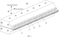
FIG. 1 is a schematic structural diagram of a coating die head according to an embodiment of the present application; -
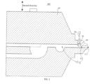
FIG. 2 is a schematic cross-sectional view of the coating die head inFIG. 1 ; -
FIG. 3 is a schematic diagram of a local structure of the coating die head inFIG. 1 ; -
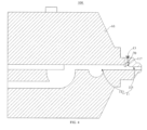
FIG. 4 is a schematic cross-sectional view of a die head body of the coating die head inFIG. 1 ; and -
FIG. 5 is a schematic structural exploded view of a driving piece and a regulator of the coating die head inFIG. 1 . -
Reference numeral Name Reference numeral Name 100 coating die head 13 communicating hole 10 die head body 30 driving piece 11 discharge channel 31 clamping head 111 discharge port 50 regulator 113 body section 51 clamping groove 115 outlet section 70 Sealing member 117 mounting groove - The objective fulfillment, functional characteristics, and advantages of the present application will be described in more detail with reference to the drawings.
- The following clearly and completely describes the technical solutions in the embodiments of the present application with reference to the accompanying drawings in the embodiments of the present application. Apparently, the described embodiments are merely some but not all of the embodiments of the present application. All other embodiments obtained by a person of ordinary skill in the art based on the embodiments of the present application without creative efforts shall fall within the protection scope of the present application.
- It is hereby noted that all directional indicators (for example, up, down, left, right, front, back, and so on) in the embodiments of the present application are merely used to explain a relative position relationship, movement state and the like between components in a specific posture (as shown in the drawings). When the specific posture changes, the directional indicators change accordingly.
- In the present application, unless otherwise specified and defined explicitly, the terms "connection", "fixation", and the like should be understood in their general senses. For example, "fixation" may refer to a fixed connection, a detachable connection, or an integral connection, may refer to a mechanical connection or an electrical connection, and may refer to a direct connection, an indirect connection via an intermediate medium, an internal communication between two elements or an interaction between two elements, unless otherwise defined explicitly. Persons of ordinary skill in the art can understand specific meanings of the above terms in the present application as appropriate to specific situations.
- In addition, the description referring to "first", "second", and the like are merely for the purpose of description, and shall not be understood as any indication or implication of relative importance or any implicit indication of the number of technical features indicated. Therefore, features defined by "first" and "second" can explicitly or implicitly include at least one of the features. In addition, the meaning of "and/or" appearing throughout the specification includes three parallel solutions. For example, "A and/or B" means a solution of only A, a solution of only B, or a solution of both A and B. Moreover, the technical solutions of the embodiments can be combined with each other as long as they can be implemented by a person of ordinary skill in the art. When the combination of the technical solutions causes a conflict or cannot be implemented, it should be considered that this combination of the technical solutions does not exist and does not fall within the protection scope claimed by the present application.
- The applicant has noted that in various coating processes, for example, in a production process of a secondary battery, a piece of coating equipment is usually required to apply a prepared pasty viscous slurry onto a substrate. However, in an actual coating process, an edge effect is likely to occur at an edge position of the slurry that is applied, that is, thicknesses of edge regions at two sides of a coating formed by the slurry are greater than a thickness of a middle region. In this case, the uneven thickness of the coating on the substrate affects the performance such as capacity of the battery, and accordingly affects the subsequent use of the battery. Therefore, to ensure normal and stable subsequent use of the battery, it is necessary to control thinning of the slurry coating on the substrate during coating. However, in the related art, to realize thickness regulation of the coating, a coating die head of a piece of coating equipment in the related art is usually provided with a movable regulator, so that the regulator is driven to move in a discharge channel to regulate a discharge flow rate of the coating die head, thereby realizing thickness regulation of the coating. However, during use of this type of coating equipment, there is a height difference between regulators when two adjacent driving pieces are driving the regulators for regulation, so that the applied coating correspondingly generates a stepped height difference, thus affecting the coating effect of the coating equipment.
- In view of the above consideration, to improve the coating effect of the coating equipment, the applicant proposes a novel coating die head. In an embodiment of the present application, with reference to
FIG. 1 andFIG. 2 , acoating die head 100 includes adie head body 10, at least two drivingpieces 30, and aregulator 50. Thedie head body 10 is provided with a discharge channel 11 in communication with an outside. The at least two drivingpieces 30 are both arranged at thedie head body 10 and distributed along a first direction, where the first direction is perpendicular to a discharge direction of the discharge channel 11. Theregulator 50 is a flexible member, at least a part of theregulator 50 is arranged in the discharge channel 11 and connected to the at least two drivingpieces 30, the drivingpieces 30 are configured to drive theregulator 50 to move along a second direction in the discharge channel 11, and the second direction is perpendicular to the first direction and the discharge direction of the discharge channel 11. - The
die head body 10 can serve as a body structure of the coating diehead 100, for forming the discharge channel 11, mounting the drivingpieces 30 and theregulator 50, and the like. The discharge channel 11 includes a feed port and adischarge port 111. A to-be-applied slurry can enter the discharge channel 11 through the feeding port and is then extruded to a substrate through thedischarge port 111, and then a coating process of the substrate is implemented. The feeding port may be a circular hole, a square hole, or the like. This is not specifically limited in the present application. The coated substrate generally has a large width, so thedischarge port 111 can extend along a width direction of the substrate to form a long strip shape, that is, extending along the first direction. In this case, thedie head body 10 is correspondingly a long strip-shaped structure extending in the first direction as well, thereby facilitating formation of the long strip-shapeddischarge port 111 in a length direction thereof. Certainly, the present application is not limited thereto. In other embodiments, thedie head body 10 may be approximately a cubic structure. The drivingpieces 30 may be configured to drive theregulator 50 to move, and the drivingpieces 30 are distributed along the first direction, so thatdifferent driving pieces 30 can drive the correspondingregulator 50 to move, thereby realizing thickness regulation of the coating in different regions in the width direction. There may be two, three, or moredriving pieces 30. This is not specifically limited in the present application. The driving of the drivingpieces 30 to theregulator 50 may be implemented as described hereinafter: the drivingpieces 30 are in threaded connection with thedie head body 10 and thus is movable while rotating with respect to thedie head body 10, thereby driving theregulator 50 connected to the drivingpieces 30 to move. Certainly, the present application is not limited thereto. In other embodiments, the drivingpieces 30 may alternatively be cylinders, linear motors, or the like, so as to automatically drive theregulator 50. In this case, theregulator 50 may be arranged at an inner side of thedie head body 10 or arranged at an outer side of thedie head body 10, as long as theregulator 50 can be driven. Theregulator 50 may be configured to regulate a discharge flow rate of the discharge channel 11. Specifically, when theregulator 50 is driven to move by the drivingpieces 30, at least a part of theregulator 50 is located in the discharge channel 11. In this way, during movement of theregulator 50, a cross section of the discharge channel 11, through which the slurry can pass at this position, can be regulated. For example, when aregulator 50 is driven to move downwards by acorresponding driving piece 30, a cross section of the discharge channel 11 in a region corresponding to theregulator 50 is reduced, so that a flow rate of the slurry passing through this position can also be reduced, and ultimately the thickness of the coating in a coated region on the substrate corresponding to theregulator 50 can be reduced as well. However, when theregulator 50 moves upwards, a cross section of the discharge channel 11 in a region corresponding to theregulator 50 is increased, so that a flow rate of the slurry passing through this position can also be increased, and ultimately the thickness of the coating in a coated region on the substrate corresponding to theregulator 50 can be increased as well. Therefore, the thickness of the coating on the corresponding region of the substrate can be regulated by driving theregulator 50 to move. Moreover, theregulator 50 is a flexible member, so that when it is driven by each drivingpiece 30, each position of theregulator 50 can well deform and can form a smooth transitional shape at a position between the corresponding twoadjacent driving pieces 30. Theregulator 50 may be rubber, silicone, or another deformable object. A specific material of theregulator 50 is not limited in the present application, as long as theregulator 50 can be driven by theregulator 50 and can deform. Further, theregulator 50 may be partially arranged in the discharge channel 11. Certainly, theregulator 50 may be entirely arranged in the discharge channel 11. Alternatively, theregulator 50 is entirely arranged outside the discharge channel 11, as long as theregulator 50 can enter the discharge channel 11 to move so as to regulate the flow rate of the slurry when theregulator 50 is subsequently driven to move by a drive component. In addition, theregulator 50 may be a block structure, a plate structure, a column structure, or the like, as long as it can regulate the discharge flow rate of the discharge channel 11 during movement. Besides, a movement direction of theregulator 50, that is the second direction, can be perpendicular to the discharge direction of the discharge channel 11 and the first direction. This enables theregulator 50 to have a relatively short movement stroke, thereby helping to improve the convenience for driving and arranging it. Moreover, theregulator 50 in this case can well regulate a cross section of the discharge channel 11 for the slurry to pass through at this corresponding position even when theregulator 50 moves a smaller distance, thereby fully regulating the discharge flow rate of the discharge channel 11. - During use of the coating die
head 100 in this solution, the slurry can be extruded out of the discharge channel 11 to a to-be-coated substrate, and then the coating process of the substrate is implemented. Moreover, the coating diehead 100 further includes the at least two drivingpieces 30 and theregulator 50, so that a discharge flow rate of the discharge channel 11 can be controlled by using the drivingpieces 30 to drive theregulator 50 to move in the discharge channel 11, thereby realizing thickness regulation of a coating applied onto the substrate. In addition, it is particularly important that theregulator 50 in this solution is a flexible member. Thus, when the drivingpieces 30 are driving theregulator 50 to move, theregulator 50 can well deform due to its flexibility, so that theregulator 50 can form a smooth transitional shape in a region between the corresponding twoadjacent driving pieces 30. In this case, the coating can also correspondingly form a smooth transitional shape in this region. In this way, generation of a stepped height difference is prevented during thickness regulation of the coating, thereby improving the coating effect of the coating equipment. - Referring to
FIG. 2 , in an embodiment of the present application, the discharge channel 11 includes abody section 113 and anoutlet section 115 that communicate with each other in sequence in the discharge direction of the discharge channel 11. A cross-sectional area of theoutlet section 115 is less than a cross-sectional area of thebody section 113, and at least a part of theregulator 50 is movable within theoutlet section 115. - The
body section 113 is a main part of the discharge channel 11 in the middle, while theoutlet section 115 is located downstream of the discharge channel 11 with respect to thebody section 113. After the slurry in thebody section 113 enters theoutlet section 115, the slurry can be extruded to the substrate through an outlet in one end that is of theoutlet section 115 and that is far away from thebody section 113. That the cross-sectional area of theoutlet section 115 is less than the cross-sectional area of thebody section 113 may mean that a size of theoutlet section 115 between two inner walls in the second direction is smaller than a size of thebody section 113 between the two inner walls in the second direction. - In this embodiment, the
outlet section 115 is closer to adischarge port 111 of the discharge channel 11 than thebody section 113, so after a flow rate of a slurry at a specific region is regulated by theregulator 50, the slurry can be quickly extruded out of thedischarge port 111 to form a coating with a required thickness, which is unlikely to flow-in of the slurry at other regions. Certainly, it should be noted that the present application is not limited thereto. In other embodiments, theregulator 50 may be arranged in thebody section 113 and close to theoutlet section 115. - Referring to
FIG. 3 , in an embodiment of the present application, theregulator 50 extends along the first direction to form a long strip-shaped structure. - The long strip-shaped structure means that the
regulator 50 is a cuboid plate structure or columnar structure, and a length direction is formed in the first direction. - In this embodiment, the
regulator 50 extends along the first direction, and the first direction corresponds to a width direction of the coating. Therefore, arranging theregulator 50 in a long strip shape allows theregulator 50 to have a relatively large regulation range, thereby helping to improve the flexibility in thickness regulation of the coating. Certainly, the present application is not limited thereto. In other embodiments, theregulator 50 may alternatively be a cube structure. - Referring to
FIG. 3 , in an embodiment of the present application, oneregulator 50 is provided, and in the first direction, a length of theregulator 50 is the same as a length of the discharge channel 11. - In this embodiment, one
regulator 50 is provided, so that components of the coating diehead 100 are significantly reduced. In this way, the structure of the coating diehead 100 is simplified, thereby helping to improve the convenience in manufacturing thereof. Moreover, there is only oneregulator 50, which can better prevent the possibility of a thickness difference of the coating betweenadjacent regulators 50. The length of theregulator 50 being the same as the length of the discharge channel 11 can ensure that theregulator 50 can still have a large regulation range when it is provided in a quite small number. Certainly, the present application is not limited thereto. In other embodiments, at least tworegulators 50 are provided as well; the at least tworegulators 50 are distributed in the first direction; eachregulator 50 is connected to at least two drivingpieces 30; and in the first direction, the lengths of the at least tworegulators 50 are the same as the length of the discharge channel 11. In this case, the arrangement of the at least tworegulators 50 ensures thatdifferent regulators 50 can be driven to move to realize thickness regulation of different regions of the coating in the width direction of the coating, thereby helping to improve the flexibility in thickness regulation of the coating. - In an embodiment of the present application, the
regulator 50 is made of an anti-corrosion material. - The anti-corrosion material means that the
regulator 50 can have acid and alkali resistance. - In this embodiment, the
regulator 50 is made of an anti-corrosion material, so that theregulator 50 can be better prevented from corrosion of the slurry during coating, thereby helping to prolong the service life of theregulator 50. Specifically, theregulator 50 may be made of anti-corrosion rubber, silicone, another anti-corrosion polymer material, or the like. - With reference to
FIG. 2 andFIG. 3 , in an embodiment of the present application, theregulator 50 is a cubic structure. - The cubic structure means that the
regulator 50 may be a rectangular structure or a square structure. - In this embodiment, the
regulator 50 is arranged as a cubic structure, so that theregulator 50 is regular in property, thereby helping to improve the convenience in processing and shaping thereof. In addition, this also allows for a large and flat contact surface between theregulator 50 and the slurry, thereby facilitating flow rate regulation and control of the slurry. Certainly, it should be noted that the present application is not limited thereto. In other embodiments, theregulator 50 may alternatively be a cylinder, a structure in another shape, or the like. - With reference to
FIG. 2 to FIG. 4 , in an embodiment of the present application, an inner wall of the discharge channel 11 is provided with a mountinggroove 117, and theregulator 50 is arranged in the mountinggroove 117. - The mounting
groove 117 may be provided in one of two opposite inner walls of the discharge channel 11 in the second direction, so that theregulator 50 is accommodated in the mountinggroove 117. The mountinggroove 117 may extend along the first direction so as to correspondingly accommodate theregulator 50 extending along the first direction. In addition, when at least tworegulators 50 are provided, the at least tworegulators 50 can both be accommodated in this one mountinggroove 117. - In this embodiment, the mounting
groove 117 can provide a mounting space for theregulator 50, thereby improving the convenience for arranging theregulator 50. Moreover, theregulator 50 can be provided with a relatively large volume, so that the strength of theregulator 50 is enhanced, thereby providing convenience for theregulator 50 to stably implement subsequent regulation work. - With reference to
FIG. 2 andFIG. 4 , in an embodiment of the present application, thedie head body 10 is provided with a communicating hole 13 which enables a communication between the mountinggroove 117 and the outside, and one end that is of the drivingpiece 30 and that is far away from theregulator 50 passes through the communicating hole 13 to extend to the outside. - One end that is of the driving
piece 30 and that is far away from theregulator 50 passes through the communicating hole 13 to extend to the outside, meaning that the drivingpiece 30 runs through the communicating hole 13, and one of two opposite ends is located at an outer side of thedie head body 10, and the other end is located inside the mountinggroove 117 and is connected to theregulator 50. - In this embodiment, at least a part of the driving
piece 30 is exposed outside, thereby facilitating a drive operation, a maintenance operation, or the like of the drivingpiece 30. - With reference to
FIG. 2 andFIG. 4 , in an embodiment of the present application, the coating diehead 100 further includes a sealing member 70, where the sealing member 70 is arranged between theregulator 50 and a wall of the mountinggroove 117 that communicates with the communicating hole 13. - The sealing member 70 may be configured to seal a space between the
regulator 50 and the wall of the mountinggroove 117 that communicates with the communicating hole 13, where the sealing member 70 may be made of rubber, silicone, or the like, so that the sealing member 70 can be attached to a position between theregulator 50 and the wall of the mountinggroove 117 that communicates with the communicating hole 13 after an elastic deformation caused by extrusion of theregulator 50, thereby ensuring a sealing effect. Besides, one sealing member 70 may be provided for sealing the space between tworegulator 50 and the wall of the mountinggroove 117 that communicates with the communicating hole 13. Certainly, the number of the sealing member 70 may correspond to the number of theregulator 50. In this case, one sealing member 70 seals the space between oneregulator 50 and the wall of the mountinggroove 117 that communicates with the communicating hole 13. - In this embodiment, by virtue of the sealing effect of the sealing member 70, even if an amount of slurry enters the mounting
groove 117, the sealing effect of the sealing member 70 prevents the slurry from further penetrating into the communicating hole 13. - With reference to
FIG. 2 andFIG. 5 , in an embodiment of the present application, the drivingpiece 30 is in threaded connection with at least a part of a section of the communicating hole 13, and the drivingpiece 30 is rotationally connected to theregulator 50. - The driving
piece 30 is in threaded connection with at least a part of a section of the communicating hole 13, meaning that the entire wall of the communicating hole 13 may be provided with an internal thread, or a part of the wall is provided with an internal thread. A lateral circumferential surface of the drivingpiece 30 is correspondingly provided with an external thread which matches with the internal thread in the communicating hole 13. The drivingpiece 30 is rotationally connected to theregulator 50, meaning that the drivingpiece 30 and theregulator 50 can rotate relative to each other in a circumferential direction, and the drivingpiece 30 is limited in a direction of the rotating axis, that is, being limited in the second direction. - In this embodiment, the driving
piece 30 is in threaded connection with thedie head body 10, so that the drivingpiece 30 is movable along the second direction while rotating and thus drives theregulator 50 connected thereto to move, so that theregulator 50 is driven by the drivingpiece 30. Moreover, in this case, the drivingpiece 30 is a pure mechanical structure for driving theregulator 50 and does not involve in a circuit, a gas circuit, and the like, thereby improving the safety of the coating diehead 100 during use. - Referring to
FIG. 5 , in an embodiment of the present application, theregulator 50 is provided with a clampinggroove 51, one end of the drivingpiece 30 is provided with a clampinghead 31, and the clampinghead 31 is clamped into the clampinggroove 51 and is rotatable in the clampinggroove 51. - The clamping
groove 51 may be a circular groove body, so that when the drivingpiece 30 rotates relative to thedie head body 10, the clampinghead 31 can also rotate in the clampinggroove 51. The clampinggroove 51 may be formed by two groove bodies that are in communication and combined with each other, where the two groove bodies have different cross sections. The clampinghead 31 may be a cylinder in shape, so as to be mounted in match with the clampinggroove 51 and rotatable in the clampinggroove 51. The clampinghead 31 may be formed by two column bodies that are connected and combined with each other, where the two column bodies have different cross sections. - In this embodiment, the driving
piece 30 and theregulator 50 are connected through clamping, achieving a simple connecting structure therefor, thereby helping to improve the convenience for assembling them. Moreover, theregulator 50 is made of a flexible material, so the clampinghead 31 may also be elastically taken out of the clampinggroove 51. In this way, the drivingpiece 30 and theregulator 50 can be disassembled, thereby helping to improve the convenience for maintaining or replacing theregulator 50 and the drivingpiece 30. Certainly, it should be noted that the present application is not limited thereto. In other embodiments, it is also possible that a part of theregulator 50 is rotationally embedded into the drivingpiece 30. - With reference to
FIG. 1 to FIG. 5 , in an embodiment of the present application, the coating diehead 100 includes adie head body 10, at least two drivingpieces 30, and aregulator 50. Thedie head body 10 is provided with a discharge channel 11 in communication with the outside. The at least two drivingpieces 30 are both arranged at thedie head body 10 and distributed along a first direction, and the first direction is perpendicular to a discharge direction of the discharge channel 11. Theregulator 50 is a flexible member, at least a part of theregulator 50 is arranged in the discharge channel 11 and connected to the at least two drivingpieces 30, the drivingpieces 30 are configured to drive theregulator 50 to move along a second direction in the discharge channel 11, and the second direction is perpendicular to the first direction and the discharge direction of the discharge channel 11. Further, the discharge channel 11 includes abody section 113 and anoutlet section 115 that communicate with each other in sequence in the discharge direction of the discharge channel 11. A cross-sectional area of theoutlet section 115 is less than a cross-sectional area of thebody section 113, and at least a part of theregulator 50 is movable within theoutlet section 115. Theregulator 50 extends along the first direction to for a long strip-shaped structure, oneregulator 50 is provided, and in the first direction, a length of theregulator 50 is the same as a length of the discharge channel 11. Theregulator 50 is made of an anti-corrosion material and is a cubic structure. Furthermore, an inner wall of the discharge channel 11 is provided with a mountinggroove 117, and theregulator 50 is arranged in the mountinggroove 117. Thedie head body 10 is provided with a communicating hole 13 which enables a communication between the mountinggroove 117 and the outside, and one end of the drivingpiece 30 far away from theregulator 50 passes through the communicating hole 13 to extend to the outside. The coating diehead 100 further includes a sealing member 70, where the sealing member 70 is arranged between theregulator 50 and a wall of the mountinggroove 117 that communicates with the communicating hole 13. The drivingpiece 30 is in threaded connection with at least a part of a section of the communicating hole 13, and the drivingpiece 30 is rotationally connected to theregulator 50. Theregulator 50 is provided with a clampinggroove 51, one end of the drivingpiece 30 is provided with a clampinghead 31, and the clampinghead 31 is clamped into the clampinggroove 51 and is rotatable in the clampinggroove 51. - The present application further discloses a piece of coating equipment. The coating equipment includes a
coating die head 100. For the specific structure of the coating diehead 100, reference may be made to the preceding embodiments. The coating equipment employs all the technical solutions of all the preceding embodiments, the coating equipment at least achieve all the beneficial effects brought by the technical solutions of the preceding embodiments, the details of which are omitted here. - The foregoing descriptions are merely preferred embodiments of the present application, but are not intended to limit the patent scope of the present application. All equivalent structural transformations made by using the content of the specification and drawings of the present application or directly/indirectly used in other related technical fields under the inventive conception of the present application are included in the patent protection scope of the present application.
Claims (13)
- A coating die head, comprising:a die head body, the die head body is provided with a discharge channel in communication with an outside;at least two driving pieces, the at least two driving pieces are both arranged at the die head body and distributed along a first direction, and the first direction is perpendicular to a discharge direction of the discharge channel; anda regulator, the regulator is a flexible member, at least a part of the regulator is arranged in the discharge channel and connected to the at least two driving pieces, the driving pieces are configured to drive the regulator to move along a second direction in the discharge channel, and the second direction is perpendicular to the first direction and the discharge direction of the discharge channel.
- The coating die head according to claim 1, wherein the discharge channel comprises a body section and an outlet section that are in communication with each other in sequence in the discharge direction of the discharge channel; and
a cross-sectional area of the outlet section of the discharge channel is less than a cross-sectional area of the body section of the discharge channel, and at least a part of the regulator is movable within the outlet section. - The coating die head according to claim 1 or 2, wherein the regulator extends along the first direction to form a long strip-shaped structure.
- The coating die head according to claim 3, wherein one regulator is provided, and in the first direction, a length of the regulator is the same as a length of the discharge channel.
- The coating die head according to claim 3, wherein at least two regulators are provided, the at least two regulators are distributed in the first direction, and each regulator is connected to the at least two driving pieces; and
in the first direction, lengths of the at least two regulators are the same as the length of the discharge channel. - The coating die head according to any one of claims 1 to 5, wherein the regulator is made of an anti-corrosion material.
- The coating die head according to any one of claims 1 to 6, wherein the regulator is a cubic structure.
- The coating die head according to any one of claims 1 to 7, wherein an inner wall of the discharge channel is provided with a mounting groove, and the regulator is arranged in the mounting groove.
- The coating die head according to claim 8, wherein the die head body is provided with a communicating hole which enables a communication between the mounting groove and the outside, and one end that is of the driving piece and that is far away from the regulator passes through the communicating hole to extend to the outside.
- The coating die head according to claim 9, wherein the coating die head further comprises a sealing member, and the sealing member is arranged between the regulator and a wall of the mounting groove that is in communication with the communicating hole.
- The coating die head according to claim 9 or 10, wherein the driving piece is in threaded connection with at least a part of a section of the communicating hole, and the driving piece is rotationally connected to the regulator.
- The coating die head according to claim 11, wherein the regulator is provided with a clamping groove, one end of the driving piece is provided with a clamping head, and the clamping head is clamped into the clamping groove and is rotatable in the clamping groove.
- A piece of coating equipment, comprising the coating die head according to any one of claims 1 to 12.
Applications Claiming Priority (2)
| Application Number | Priority Date | Filing Date | Title |
|---|---|---|---|
| CN202223186340.7U CN218945476U (en) | 2022-11-29 | 2022-11-29 | Coating die head and coating equipment |
| PCT/CN2023/119093 WO2024114049A1 (en) | 2022-11-29 | 2023-09-15 | Coating die and coating device |
Publications (2)
| Publication Number | Publication Date |
|---|---|
| EP4523799A1 true EP4523799A1 (en) | 2025-03-19 |
| EP4523799A4 EP4523799A4 (en) | 2025-10-29 |
Family
ID=86141026
Family Applications (1)
| Application Number | Title | Priority Date | Filing Date |
|---|---|---|---|
| EP23896206.2A Pending EP4523799A4 (en) | 2022-11-29 | 2023-09-15 | COATING NOZZLE AND COATING DEVICE |
Country Status (4)
| Country | Link |
|---|---|
| US (1) | US12427540B2 (en) |
| EP (1) | EP4523799A4 (en) |
| CN (1) | CN218945476U (en) |
| WO (1) | WO2024114049A1 (en) |
Families Citing this family (3)
| Publication number | Priority date | Publication date | Assignee | Title |
|---|---|---|---|---|
| CN218945476U (en) * | 2022-11-29 | 2023-05-02 | 宁德时代新能源科技股份有限公司 | Coating die head and coating equipment |
| CN219003572U (en) * | 2023-01-28 | 2023-05-12 | 宁德时代新能源科技股份有限公司 | Coating dies, coating equipment and battery production equipment |
| CN116618237A (en) * | 2023-06-28 | 2023-08-22 | 邢台海裕锂能电池设备有限公司 | A fine-tuning structure for flow uniformity in coating die |
Family Cites Families (76)
| Publication number | Priority date | Publication date | Assignee | Title |
|---|---|---|---|---|
| US3036551A (en) * | 1959-10-19 | 1962-05-29 | George W Shreckhise | Apparatus for coating fabrics |
| US3461841A (en) * | 1967-01-13 | 1969-08-19 | Ibm | Apparatus for coating a thin,uniform thickness stripe on a substrate |
| JPS5575758A (en) * | 1978-12-06 | 1980-06-07 | Fuji Photo Film Co Ltd | Coating method and apparatus therefor |
| US4520049A (en) * | 1983-01-24 | 1985-05-28 | Kao Corporation | Method and apparatus for coating |
| JP2748994B2 (en) * | 1991-05-24 | 1998-05-13 | 宇部興産株式会社 | Parison thickness control |
| US5294258A (en) * | 1992-04-08 | 1994-03-15 | Nordson Corporation | Apparatus for producing an integral adhesive matrix |
| JP3122568B2 (en) * | 1993-10-19 | 2001-01-09 | 富士写真フイルム株式会社 | Coating device |
| JP3224113B2 (en) * | 1993-10-20 | 2001-10-29 | 富士写真フイルム株式会社 | Application method |
| US6808565B1 (en) * | 1995-10-06 | 2004-10-26 | Seed Rubber Co., Ltd. | Clutch mechanism of coat film transfer tool and coat film transfer tool |
| CA2288031C (en) * | 1997-05-09 | 2007-03-27 | Valmet Corporation | Method and an apparatus for coating paperboard |
| EP0993524B1 (en) * | 1997-06-30 | 2002-11-20 | Beloit Technologies, Inc. | Method and apparatus for the high speed application of coating to a traveling paper web |
| US6410094B2 (en) * | 1998-02-19 | 2002-06-25 | Fuji Photo Film Co., Ltd. | Extrusion coating head and coating method for flexible support |
| ES2185565T3 (en) * | 1999-02-11 | 2003-05-01 | Alcan Int Ltd | PROCEDURE AND APPLIANCE FOR PROFILE CONTROL IN A DIRECT COATING MACHINE. |
| HUP0101103A2 (en) * | 2000-03-17 | 2001-11-28 | Sony Corporation | Method and equipment for manufacturing thereof dry reserve accumulators |
| JP4596614B2 (en) * | 2000-08-04 | 2010-12-08 | 東芝機械株式会社 | A device that intermittently coats the surface of a substrate |
| JP4711495B2 (en) * | 2000-08-08 | 2011-06-29 | スリーエム イノベイティブ プロパティズ カンパニー | Coating device |
| AUPR057500A0 (en) * | 2000-10-05 | 2000-10-26 | Commonwealth Scientific And Industrial Research Organisation | Treating fabric for manufacturing filter bags |
| JP2003181355A (en) * | 2001-12-20 | 2003-07-02 | Labo:Kk | Coating agent supply nozzle |
| CN100430151C (en) * | 2002-07-18 | 2008-11-05 | 大日本印刷株式会社 | Coating dies and coating equipment |
| US7083826B2 (en) * | 2003-05-16 | 2006-08-01 | 3M Innovative Properties Company | Coating die and method for use |
| US7092855B2 (en) * | 2003-05-30 | 2006-08-15 | Avery Dennison Corporation | Thermo-stable coating die design method and apparatus |
| JP4399859B2 (en) * | 2003-09-17 | 2010-01-20 | 富士フイルム株式会社 | Coating head and coating device |
| JP4358010B2 (en) * | 2004-03-25 | 2009-11-04 | 富士フイルム株式会社 | Coating apparatus and coating method |
| JP4752275B2 (en) * | 2005-01-27 | 2011-08-17 | 凸版印刷株式会社 | Coating device |
| US7927668B2 (en) * | 2005-04-12 | 2011-04-19 | Toray Industries, Inc. | Coater of electric insulating sheet and method for producing electric insulating sheet with coated film |
| JP2007268385A (en) * | 2006-03-30 | 2007-10-18 | Fujifilm Corp | Coating apparatus, coating method, and optical film manufacturing method |
| JP4833720B2 (en) * | 2006-04-19 | 2011-12-07 | 富士フイルム株式会社 | Coating liquid coating method and apparatus |
| US8123511B2 (en) * | 2007-05-03 | 2012-02-28 | Cloeren Incorporated | Decoupled transverse flow metering gap and lip gap |
| WO2009075155A1 (en) * | 2007-12-10 | 2009-06-18 | Toyota Jidosha Kabushiki Kaisha | Coating apparatus and method of applying coating liquid |
| EP2240285A4 (en) * | 2007-12-31 | 2012-08-01 | 3M Innovative Properties Co | Method for applying a coatable material |
| KR101125649B1 (en) * | 2010-05-24 | 2012-03-27 | 삼성에스디아이 주식회사 | Active material coating apparatus and coating method using the same |
| JP5442054B2 (en) * | 2012-02-23 | 2014-03-12 | パナソニック株式会社 | Coating apparatus and coating method |
| JP5912762B2 (en) * | 2012-03-29 | 2016-04-27 | 日東電工株式会社 | Die coater and coating film manufacturing method |
| WO2015009033A1 (en) * | 2013-07-16 | 2015-01-22 | 주식회사 엘지화학 | Member for slot die coater, movable member for slot die coater, and slot die coater for producing electrode employing same |
| JP6310741B2 (en) * | 2014-03-20 | 2018-04-11 | 株式会社Screenホールディングス | Intermittent coating method and intermittent coating apparatus |
| US20150352589A1 (en) * | 2014-06-05 | 2015-12-10 | The Procter & Gamble Company | Methods and Apparatus for Applying Adhesives in Patterns to an Advancing Substrate |
| CN107073506B (en) * | 2014-11-05 | 2019-07-05 | 3M创新有限公司 | For coating the mold and its application method with flow resistance device of suspension |
| KR101877101B1 (en) * | 2015-07-28 | 2018-08-09 | 주식회사 엘지화학 | Electrode active material slurry coting apparatus and method |
| KR101578765B1 (en) * | 2015-09-24 | 2015-12-18 | 성안기계 주식회사 | Slot die coating apparatus and method for controlling the same |
| KR101985422B1 (en) * | 2016-10-27 | 2019-06-03 | 성안기계 주식회사 | Slot die with variable nozzle |
| KR101922054B1 (en) * | 2017-04-26 | 2018-11-26 | 성안기계 주식회사 | Slot die with variable manifold and method for controlling the same |
| CN113056334B (en) * | 2018-12-18 | 2023-05-02 | 松下知识产权经营株式会社 | Intermittent coating device |
| KR102521454B1 (en) * | 2019-09-19 | 2023-04-14 | 주식회사 엘지에너지솔루션 | Coating die having a double slit and coating device of electrode active material using the same |
| US12594573B2 (en) * | 2020-07-14 | 2026-04-07 | Lg Energy Solution, Ltd. | Die coater and inspection device thereof |
| KR102633516B1 (en) * | 2020-07-14 | 2024-02-06 | 주식회사 엘지에너지솔루션 | The Apparatus And The Method For Inspecting Die Coater |
| KR102891881B1 (en) * | 2020-07-16 | 2025-11-26 | 주식회사 엘지에너지솔루션 | Dual slot die coater |
| EP4134169B1 (en) * | 2020-08-03 | 2026-04-22 | LG Energy Solution, Ltd. | Multi-slot die coater |
| CN115052688B (en) * | 2020-08-03 | 2024-05-14 | 株式会社Lg新能源 | Multi-slit die coater |
| HUE071820T2 (en) * | 2020-08-20 | 2025-09-28 | Lg Energy Solution Ltd | Multi-slot die coater |
| WO2022045684A1 (en) * | 2020-08-26 | 2022-03-03 | 주식회사 엘지에너지솔루션 | Multiple slot die coater |
| EP4148815B1 (en) * | 2020-09-17 | 2025-04-02 | LG Energy Solution, Ltd. | Dual slot die coater and method for coating electrode active material slurry using the same |
| KR20220043029A (en) * | 2020-09-28 | 2022-04-05 | 주식회사 엘지에너지솔루션 | Multiple slot die coater |
| EP4147791B1 (en) * | 2020-09-28 | 2026-04-01 | LG Energy Solution, Ltd. | Dual slot die coater |
| CN115551648A (en) * | 2020-09-28 | 2022-12-30 | 株式会社Lg新能源 | Multi-slot die coater |
| ES3066888T3 (en) * | 2020-11-13 | 2026-05-18 | Lg Energy Solution Ltd | Dual slot die coater including air vent |
| KR102891883B1 (en) * | 2020-11-24 | 2025-11-26 | 주식회사 엘지에너지솔루션 | Slot die coater with improved coating fluid flow |
| KR102638268B1 (en) * | 2020-11-24 | 2024-02-16 | 주식회사 엘지에너지솔루션 | Slot die coater with improved coating fluid flow |
| CN112676106B (en) * | 2020-12-16 | 2021-08-10 | 安脉时代智能制造(宁德)有限公司 | Integral adjusting strip coating die head |
| KR102969753B1 (en) * | 2020-12-29 | 2026-05-26 | 주식회사 엘지에너지솔루션 | Dual slot die coater |
| CN112893019A (en) * | 2021-02-05 | 2021-06-04 | 深圳市曼恩斯特科技股份有限公司 | Adjustment mechanism, mould, coating die head and coating equipment |
| CN215030645U (en) * | 2021-05-26 | 2021-12-07 | 宁德时代新能源科技股份有限公司 | a coating equipment |
| KR102885970B1 (en) * | 2021-10-12 | 2025-11-12 | 주식회사 엘지에너지솔루션 | Coating die for lithium secondary battery including removable spacer shims |
| CN216322970U (en) | 2021-10-20 | 2022-04-19 | 宁德时代新能源科技股份有限公司 | Extrusion head of coating machine and coating machine |
| CN216323035U (en) * | 2021-11-02 | 2022-04-19 | 江苏时代新能源科技有限公司 | Coating device and coating system |
| JP7566152B2 (en) * | 2021-11-29 | 2024-10-11 | エルジー エナジー ソリューション リミテッド | Dual Slot Die Coater |
| CN216459791U (en) | 2021-11-30 | 2022-05-10 | 深圳市曼恩斯特科技股份有限公司 | Coating die head and coating machine thereof |
| EP4272878B1 (en) * | 2021-12-08 | 2025-10-15 | LG Energy Solution, Ltd. | Slot die shim and slot die including same |
| JP7848692B2 (en) * | 2021-12-16 | 2026-04-21 | 東レ株式会社 | Slot-type spray nozzle, coating apparatus, and method for manufacturing coated member. |
| CN217140968U (en) * | 2022-03-14 | 2022-08-09 | 宁德时代新能源科技股份有限公司 | Coating die head and coating device of battery pole piece |
| CN117299478B (en) * | 2022-06-22 | 2026-06-30 | 宁德时代新能源科技股份有限公司 | Coating die head and coating machine |
| US20240165655A1 (en) * | 2022-11-21 | 2024-05-23 | Contemporary Amperex Technology Co., Limited | Coating equipment |
| WO2024113156A1 (en) * | 2022-11-29 | 2024-06-06 | 宁德时代新能源科技股份有限公司 | Coating die and coating device |
| CN218945476U (en) * | 2022-11-29 | 2023-05-02 | 宁德时代新能源科技股份有限公司 | Coating die head and coating equipment |
| CN219003572U (en) * | 2023-01-28 | 2023-05-12 | 宁德时代新能源科技股份有限公司 | Coating dies, coating equipment and battery production equipment |
| JP2024120469A (en) * | 2023-02-24 | 2024-09-05 | 株式会社Screenホールディングス | SUBSTRATE PROCESSING APPARATUS AND SUBSTRATE PROCESSING METHOD |
| EP4534210B1 (en) * | 2023-09-25 | 2026-04-15 | LG Energy Solution, Ltd. | Die coater for coating electrode slurry and insulating liquid |
-
2022
- 2022-11-29 CN CN202223186340.7U patent/CN218945476U/en active Active
-
2023
- 2023-09-15 WO PCT/CN2023/119093 patent/WO2024114049A1/en not_active Ceased
- 2023-09-15 EP EP23896206.2A patent/EP4523799A4/en active Pending
-
2025
- 2025-01-16 US US19/023,440 patent/US12427540B2/en active Active
Also Published As
| Publication number | Publication date |
|---|---|
| WO2024114049A1 (en) | 2024-06-06 |
| US12427540B2 (en) | 2025-09-30 |
| EP4523799A4 (en) | 2025-10-29 |
| CN218945476U (en) | 2023-05-02 |
| US20250153211A1 (en) | 2025-05-15 |
Similar Documents
| Publication | Publication Date | Title |
|---|---|---|
| US12427540B2 (en) | Coating die head and coating equipment | |
| EP4588575A1 (en) | Coating die and coating apparatus | |
| US10760172B2 (en) | Film forming method for metal film and film forming apparatus therefor | |
| CN216225120U (en) | Extrusion coating head and coating device | |
| EP4095400A1 (en) | Height-adjustable stand column clearance sheet mounting assembly and height-adjustable stand column | |
| KR20190070846A (en) | Battery pack manufacturing method | |
| EP4400222A1 (en) | Coating die and coating device | |
| CN114682439A (en) | Staggered lip coating die head | |
| US12551919B2 (en) | Coating die, coating apparatus, and battery production apparatus | |
| KR20220156221A (en) | Slot die coater manufacturing battery electrode | |
| CN211989448U (en) | Coating die | |
| CN112871579A (en) | Double-layer coating die head and coating machine | |
| CN216880143U (en) | Coating die head and coating device | |
| US20240001426A1 (en) | Feeding device and battery production apparatus | |
| CN221602412U (en) | Coating device with adjustable height | |
| CN223367342U (en) | Coating die head of high efficiency regulation | |
| CN113996697B (en) | Multilayer spiral retaining ring both ends end stamping die | |
| CN212257574U (en) | Single cell structure and fuel cell | |
| CN215943501U (en) | carrier tape guide | |
| CN221233165U (en) | Extrusion molding die | |
| CN224127688U (en) | A coating die capable of coarse and fine adjustment | |
| WO2023015458A1 (en) | Battery electrode plate coating apparatus | |
| CN214898534U (en) | Head sealing mechanism and battery heat sealing device | |
| CN218013740U (en) | Coating device | |
| CN222035470U (en) | Coating die and coating equipment |
Legal Events
| Date | Code | Title | Description |
|---|---|---|---|
| STAA | Information on the status of an ep patent application or granted ep patent |
Free format text: STATUS: THE INTERNATIONAL PUBLICATION HAS BEEN MADE |
|
| PUAI | Public reference made under article 153(3) epc to a published international application that has entered the european phase |
Free format text: ORIGINAL CODE: 0009012 |
|
| STAA | Information on the status of an ep patent application or granted ep patent |
Free format text: STATUS: REQUEST FOR EXAMINATION WAS MADE |
|
| 17P | Request for examination filed |
Effective date: 20241212 |
|
| AK | Designated contracting states |
Kind code of ref document: A1 Designated state(s): AL AT BE BG CH CY CZ DE DK EE ES FI FR GB GR HR HU IE IS IT LI LT LU LV MC ME MK MT NL NO PL PT RO RS SE SI SK SM TR |
|
| A4 | Supplementary search report drawn up and despatched |
Effective date: 20250925 |
|
| RIC1 | Information provided on ipc code assigned before grant |
Ipc: B05C 5/02 20060101AFI20250919BHEP Ipc: B05C 11/10 20060101ALI20250919BHEP |
|
| DAV | Request for validation of the european patent (deleted) | ||
| DAX | Request for extension of the european patent (deleted) |