EP4523661A2 - Orthopaedic implant systems including fixation features - Google Patents
Orthopaedic implant systems including fixation features Download PDFInfo
- Publication number
- EP4523661A2 EP4523661A2 EP25155689.0A EP25155689A EP4523661A2 EP 4523661 A2 EP4523661 A2 EP 4523661A2 EP 25155689 A EP25155689 A EP 25155689A EP 4523661 A2 EP4523661 A2 EP 4523661A2
- Authority
- EP
- European Patent Office
- Prior art keywords
- flange
- collar
- dimensioned
- bone
- engagement
- Prior art date
- Legal status (The legal status is an assumption and is not a legal conclusion. Google has not performed a legal analysis and makes no representation as to the accuracy of the status listed.)
- Granted
Links
Images






Classifications
-
- A—HUMAN NECESSITIES
- A61—MEDICAL OR VETERINARY SCIENCE; HYGIENE
- A61F—FILTERS IMPLANTABLE INTO BLOOD VESSELS; PROSTHESES; DEVICES PROVIDING PATENCY TO, OR PREVENTING COLLAPSING OF, TUBULAR STRUCTURES OF THE BODY, e.g. STENTS; ORTHOPAEDIC, NURSING OR CONTRACEPTIVE DEVICES; FOMENTATION; TREATMENT OR PROTECTION OF EYES OR EARS; BANDAGES, DRESSINGS OR ABSORBENT PADS; FIRST-AID KITS
- A61F2/00—Filters implantable into blood vessels; Prostheses, i.e. artificial substitutes or replacements for parts of the body; Appliances for connecting them with the body; Devices providing patency to, or preventing collapsing of, tubular structures of the body, e.g. stents
- A61F2/02—Prostheses implantable into the body
- A61F2/30—Joints
- A61F2/30721—Accessories
- A61F2/30749—Fixation appliances for connecting prostheses to the body
-
- A—HUMAN NECESSITIES
- A61—MEDICAL OR VETERINARY SCIENCE; HYGIENE
- A61F—FILTERS IMPLANTABLE INTO BLOOD VESSELS; PROSTHESES; DEVICES PROVIDING PATENCY TO, OR PREVENTING COLLAPSING OF, TUBULAR STRUCTURES OF THE BODY, e.g. STENTS; ORTHOPAEDIC, NURSING OR CONTRACEPTIVE DEVICES; FOMENTATION; TREATMENT OR PROTECTION OF EYES OR EARS; BANDAGES, DRESSINGS OR ABSORBENT PADS; FIRST-AID KITS
- A61F2/00—Filters implantable into blood vessels; Prostheses, i.e. artificial substitutes or replacements for parts of the body; Appliances for connecting them with the body; Devices providing patency to, or preventing collapsing of, tubular structures of the body, e.g. stents
- A61F2/02—Prostheses implantable into the body
- A61F2/30—Joints
- A61F2/30721—Accessories
- A61F2/30734—Modular inserts, sleeves or augments, e.g. placed on proximal part of stem for fixation purposes or wedges for bridging a bone defect
-
- A—HUMAN NECESSITIES
- A61—MEDICAL OR VETERINARY SCIENCE; HYGIENE
- A61F—FILTERS IMPLANTABLE INTO BLOOD VESSELS; PROSTHESES; DEVICES PROVIDING PATENCY TO, OR PREVENTING COLLAPSING OF, TUBULAR STRUCTURES OF THE BODY, e.g. STENTS; ORTHOPAEDIC, NURSING OR CONTRACEPTIVE DEVICES; FOMENTATION; TREATMENT OR PROTECTION OF EYES OR EARS; BANDAGES, DRESSINGS OR ABSORBENT PADS; FIRST-AID KITS
- A61F2/00—Filters implantable into blood vessels; Prostheses, i.e. artificial substitutes or replacements for parts of the body; Appliances for connecting them with the body; Devices providing patency to, or preventing collapsing of, tubular structures of the body, e.g. stents
- A61F2/02—Prostheses implantable into the body
- A61F2/30—Joints
- A61F2/40—Joints for shoulders
- A61F2/4014—Humeral heads or necks; Connections of endoprosthetic heads or necks to endoprosthetic humeral shafts
-
- A—HUMAN NECESSITIES
- A61—MEDICAL OR VETERINARY SCIENCE; HYGIENE
- A61B—DIAGNOSIS; SURGERY; IDENTIFICATION
- A61B17/00—Surgical instruments, devices or methods
- A61B17/56—Surgical instruments or methods for treatment of bones or joints; Devices specially adapted therefor
- A61B17/58—Surgical instruments or methods for treatment of bones or joints; Devices specially adapted therefor for osteosynthesis, e.g. bone plates, screws or setting implements
- A61B17/68—Internal fixation devices, including fasteners and spinal fixators, even if a part thereof projects from the skin
- A61B17/72—Intramedullary devices, e.g. pins or nails
-
- A—HUMAN NECESSITIES
- A61—MEDICAL OR VETERINARY SCIENCE; HYGIENE
- A61F—FILTERS IMPLANTABLE INTO BLOOD VESSELS; PROSTHESES; DEVICES PROVIDING PATENCY TO, OR PREVENTING COLLAPSING OF, TUBULAR STRUCTURES OF THE BODY, e.g. STENTS; ORTHOPAEDIC, NURSING OR CONTRACEPTIVE DEVICES; FOMENTATION; TREATMENT OR PROTECTION OF EYES OR EARS; BANDAGES, DRESSINGS OR ABSORBENT PADS; FIRST-AID KITS
- A61F2/00—Filters implantable into blood vessels; Prostheses, i.e. artificial substitutes or replacements for parts of the body; Appliances for connecting them with the body; Devices providing patency to, or preventing collapsing of, tubular structures of the body, e.g. stents
- A61F2/02—Prostheses implantable into the body
- A61F2/30—Joints
- A61F2/40—Joints for shoulders
- A61F2/4059—Humeral shafts
-
- A—HUMAN NECESSITIES
- A61—MEDICAL OR VETERINARY SCIENCE; HYGIENE
- A61F—FILTERS IMPLANTABLE INTO BLOOD VESSELS; PROSTHESES; DEVICES PROVIDING PATENCY TO, OR PREVENTING COLLAPSING OF, TUBULAR STRUCTURES OF THE BODY, e.g. STENTS; ORTHOPAEDIC, NURSING OR CONTRACEPTIVE DEVICES; FOMENTATION; TREATMENT OR PROTECTION OF EYES OR EARS; BANDAGES, DRESSINGS OR ABSORBENT PADS; FIRST-AID KITS
- A61F2/00—Filters implantable into blood vessels; Prostheses, i.e. artificial substitutes or replacements for parts of the body; Appliances for connecting them with the body; Devices providing patency to, or preventing collapsing of, tubular structures of the body, e.g. stents
- A61F2/02—Prostheses implantable into the body
- A61F2/30—Joints
- A61F2002/30001—Additional features of subject-matter classified in A61F2/28, A61F2/30 and subgroups thereof
- A61F2002/30316—The prosthesis having different structural features at different locations within the same prosthesis; Connections between prosthetic parts; Special structural features of bone or joint prostheses not otherwise provided for
- A61F2002/30329—Connections or couplings between prosthetic parts, e.g. between modular parts; Connecting elements
- A61F2002/30331—Connections or couplings between prosthetic parts, e.g. between modular parts; Connecting elements made by longitudinally pushing a protrusion into a complementarily-shaped recess, e.g. held by friction fit
-
- A—HUMAN NECESSITIES
- A61—MEDICAL OR VETERINARY SCIENCE; HYGIENE
- A61F—FILTERS IMPLANTABLE INTO BLOOD VESSELS; PROSTHESES; DEVICES PROVIDING PATENCY TO, OR PREVENTING COLLAPSING OF, TUBULAR STRUCTURES OF THE BODY, e.g. STENTS; ORTHOPAEDIC, NURSING OR CONTRACEPTIVE DEVICES; FOMENTATION; TREATMENT OR PROTECTION OF EYES OR EARS; BANDAGES, DRESSINGS OR ABSORBENT PADS; FIRST-AID KITS
- A61F2/00—Filters implantable into blood vessels; Prostheses, i.e. artificial substitutes or replacements for parts of the body; Appliances for connecting them with the body; Devices providing patency to, or preventing collapsing of, tubular structures of the body, e.g. stents
- A61F2/02—Prostheses implantable into the body
- A61F2/30—Joints
- A61F2002/30001—Additional features of subject-matter classified in A61F2/28, A61F2/30 and subgroups thereof
- A61F2002/30316—The prosthesis having different structural features at different locations within the same prosthesis; Connections between prosthetic parts; Special structural features of bone or joint prostheses not otherwise provided for
- A61F2002/30329—Connections or couplings between prosthetic parts, e.g. between modular parts; Connecting elements
- A61F2002/30331—Connections or couplings between prosthetic parts, e.g. between modular parts; Connecting elements made by longitudinally pushing a protrusion into a complementarily-shaped recess, e.g. held by friction fit
- A61F2002/30332—Conically- or frustoconically-shaped protrusion and recess
-
- A—HUMAN NECESSITIES
- A61—MEDICAL OR VETERINARY SCIENCE; HYGIENE
- A61F—FILTERS IMPLANTABLE INTO BLOOD VESSELS; PROSTHESES; DEVICES PROVIDING PATENCY TO, OR PREVENTING COLLAPSING OF, TUBULAR STRUCTURES OF THE BODY, e.g. STENTS; ORTHOPAEDIC, NURSING OR CONTRACEPTIVE DEVICES; FOMENTATION; TREATMENT OR PROTECTION OF EYES OR EARS; BANDAGES, DRESSINGS OR ABSORBENT PADS; FIRST-AID KITS
- A61F2/00—Filters implantable into blood vessels; Prostheses, i.e. artificial substitutes or replacements for parts of the body; Appliances for connecting them with the body; Devices providing patency to, or preventing collapsing of, tubular structures of the body, e.g. stents
- A61F2/02—Prostheses implantable into the body
- A61F2/30—Joints
- A61F2002/30001—Additional features of subject-matter classified in A61F2/28, A61F2/30 and subgroups thereof
- A61F2002/30316—The prosthesis having different structural features at different locations within the same prosthesis; Connections between prosthetic parts; Special structural features of bone or joint prostheses not otherwise provided for
- A61F2002/30329—Connections or couplings between prosthetic parts, e.g. between modular parts; Connecting elements
- A61F2002/30383—Connections or couplings between prosthetic parts, e.g. between modular parts; Connecting elements made by laterally inserting a protrusion, e.g. a rib into a complementarily-shaped groove
-
- A—HUMAN NECESSITIES
- A61—MEDICAL OR VETERINARY SCIENCE; HYGIENE
- A61F—FILTERS IMPLANTABLE INTO BLOOD VESSELS; PROSTHESES; DEVICES PROVIDING PATENCY TO, OR PREVENTING COLLAPSING OF, TUBULAR STRUCTURES OF THE BODY, e.g. STENTS; ORTHOPAEDIC, NURSING OR CONTRACEPTIVE DEVICES; FOMENTATION; TREATMENT OR PROTECTION OF EYES OR EARS; BANDAGES, DRESSINGS OR ABSORBENT PADS; FIRST-AID KITS
- A61F2/00—Filters implantable into blood vessels; Prostheses, i.e. artificial substitutes or replacements for parts of the body; Appliances for connecting them with the body; Devices providing patency to, or preventing collapsing of, tubular structures of the body, e.g. stents
- A61F2/02—Prostheses implantable into the body
- A61F2/30—Joints
- A61F2002/30001—Additional features of subject-matter classified in A61F2/28, A61F2/30 and subgroups thereof
- A61F2002/30316—The prosthesis having different structural features at different locations within the same prosthesis; Connections between prosthetic parts; Special structural features of bone or joint prostheses not otherwise provided for
- A61F2002/30329—Connections or couplings between prosthetic parts, e.g. between modular parts; Connecting elements
- A61F2002/30433—Connections or couplings between prosthetic parts, e.g. between modular parts; Connecting elements using additional screws, bolts, dowels, rivets or washers e.g. connecting screws
-
- A—HUMAN NECESSITIES
- A61—MEDICAL OR VETERINARY SCIENCE; HYGIENE
- A61F—FILTERS IMPLANTABLE INTO BLOOD VESSELS; PROSTHESES; DEVICES PROVIDING PATENCY TO, OR PREVENTING COLLAPSING OF, TUBULAR STRUCTURES OF THE BODY, e.g. STENTS; ORTHOPAEDIC, NURSING OR CONTRACEPTIVE DEVICES; FOMENTATION; TREATMENT OR PROTECTION OF EYES OR EARS; BANDAGES, DRESSINGS OR ABSORBENT PADS; FIRST-AID KITS
- A61F2/00—Filters implantable into blood vessels; Prostheses, i.e. artificial substitutes or replacements for parts of the body; Appliances for connecting them with the body; Devices providing patency to, or preventing collapsing of, tubular structures of the body, e.g. stents
- A61F2/02—Prostheses implantable into the body
- A61F2/30—Joints
- A61F2002/30001—Additional features of subject-matter classified in A61F2/28, A61F2/30 and subgroups thereof
- A61F2002/30316—The prosthesis having different structural features at different locations within the same prosthesis; Connections between prosthetic parts; Special structural features of bone or joint prostheses not otherwise provided for
- A61F2002/30535—Special structural features of bone or joint prostheses not otherwise provided for
- A61F2002/30604—Special structural features of bone or joint prostheses not otherwise provided for modular
-
- A—HUMAN NECESSITIES
- A61—MEDICAL OR VETERINARY SCIENCE; HYGIENE
- A61F—FILTERS IMPLANTABLE INTO BLOOD VESSELS; PROSTHESES; DEVICES PROVIDING PATENCY TO, OR PREVENTING COLLAPSING OF, TUBULAR STRUCTURES OF THE BODY, e.g. STENTS; ORTHOPAEDIC, NURSING OR CONTRACEPTIVE DEVICES; FOMENTATION; TREATMENT OR PROTECTION OF EYES OR EARS; BANDAGES, DRESSINGS OR ABSORBENT PADS; FIRST-AID KITS
- A61F2/00—Filters implantable into blood vessels; Prostheses, i.e. artificial substitutes or replacements for parts of the body; Appliances for connecting them with the body; Devices providing patency to, or preventing collapsing of, tubular structures of the body, e.g. stents
- A61F2/02—Prostheses implantable into the body
- A61F2/30—Joints
- A61F2002/30001—Additional features of subject-matter classified in A61F2/28, A61F2/30 and subgroups thereof
- A61F2002/30316—The prosthesis having different structural features at different locations within the same prosthesis; Connections between prosthetic parts; Special structural features of bone or joint prostheses not otherwise provided for
- A61F2002/30535—Special structural features of bone or joint prostheses not otherwise provided for
- A61F2002/30604—Special structural features of bone or joint prostheses not otherwise provided for modular
- A61F2002/30616—Sets comprising a plurality of prosthetic parts of different sizes or orientations
-
- A—HUMAN NECESSITIES
- A61—MEDICAL OR VETERINARY SCIENCE; HYGIENE
- A61F—FILTERS IMPLANTABLE INTO BLOOD VESSELS; PROSTHESES; DEVICES PROVIDING PATENCY TO, OR PREVENTING COLLAPSING OF, TUBULAR STRUCTURES OF THE BODY, e.g. STENTS; ORTHOPAEDIC, NURSING OR CONTRACEPTIVE DEVICES; FOMENTATION; TREATMENT OR PROTECTION OF EYES OR EARS; BANDAGES, DRESSINGS OR ABSORBENT PADS; FIRST-AID KITS
- A61F2/00—Filters implantable into blood vessels; Prostheses, i.e. artificial substitutes or replacements for parts of the body; Appliances for connecting them with the body; Devices providing patency to, or preventing collapsing of, tubular structures of the body, e.g. stents
- A61F2/02—Prostheses implantable into the body
- A61F2/30—Joints
- A61F2/40—Joints for shoulders
- A61F2/4014—Humeral heads or necks; Connections of endoprosthetic heads or necks to endoprosthetic humeral shafts
- A61F2002/4029—Necks
-
- A—HUMAN NECESSITIES
- A61—MEDICAL OR VETERINARY SCIENCE; HYGIENE
- A61F—FILTERS IMPLANTABLE INTO BLOOD VESSELS; PROSTHESES; DEVICES PROVIDING PATENCY TO, OR PREVENTING COLLAPSING OF, TUBULAR STRUCTURES OF THE BODY, e.g. STENTS; ORTHOPAEDIC, NURSING OR CONTRACEPTIVE DEVICES; FOMENTATION; TREATMENT OR PROTECTION OF EYES OR EARS; BANDAGES, DRESSINGS OR ABSORBENT PADS; FIRST-AID KITS
- A61F2/00—Filters implantable into blood vessels; Prostheses, i.e. artificial substitutes or replacements for parts of the body; Appliances for connecting them with the body; Devices providing patency to, or preventing collapsing of, tubular structures of the body, e.g. stents
- A61F2/02—Prostheses implantable into the body
- A61F2/30—Joints
- A61F2/40—Joints for shoulders
- A61F2/4014—Humeral heads or necks; Connections of endoprosthetic heads or necks to endoprosthetic humeral shafts
- A61F2002/4037—Connections of heads to necks
-
- A—HUMAN NECESSITIES
- A61—MEDICAL OR VETERINARY SCIENCE; HYGIENE
- A61F—FILTERS IMPLANTABLE INTO BLOOD VESSELS; PROSTHESES; DEVICES PROVIDING PATENCY TO, OR PREVENTING COLLAPSING OF, TUBULAR STRUCTURES OF THE BODY, e.g. STENTS; ORTHOPAEDIC, NURSING OR CONTRACEPTIVE DEVICES; FOMENTATION; TREATMENT OR PROTECTION OF EYES OR EARS; BANDAGES, DRESSINGS OR ABSORBENT PADS; FIRST-AID KITS
- A61F2/00—Filters implantable into blood vessels; Prostheses, i.e. artificial substitutes or replacements for parts of the body; Appliances for connecting them with the body; Devices providing patency to, or preventing collapsing of, tubular structures of the body, e.g. stents
- A61F2/02—Prostheses implantable into the body
- A61F2/30—Joints
- A61F2/40—Joints for shoulders
- A61F2/4014—Humeral heads or necks; Connections of endoprosthetic heads or necks to endoprosthetic humeral shafts
- A61F2002/4044—Connections of necks to shafts
Definitions
- This disclosure relates to orthopaedic procedures and, more particularly, to orthopaedic implant systems and methods for repairing bone defects and restoring functionality to a joint.
- Joints may be established by at least one long bone.
- the patient may experience loss caused by fracturing or shattering of the bone due to trauma.
- a prosthesis may be utilized to restore functionality to the bone.
- the prosthesis may include a stem insertable in a remainder of the bone and may include a head for mounting an articulation member to restore functionality to a joint.
- US 6 228 120 B1 discloses surgical equipment for implanting a total shoulder prosthesis, and total shoulder prosthesis constituting same.
- EP 0 679 375 A1 discloses a modular prosthetic assembly for the shoulder joint.
- WO 03/005933 A2 discloses shoulder prosthesis.
- DE 299 18 589 U1 discloses an endoprosthesis for a shoulder joint.
- WO 2015/103313 A1 discloses instruments and techniques for orienting prosthesis components for joint prostheses.
- the implant systems may include one or more fixation features for securing components of the implant systems to each other and/or adjacent tissue of a patient.
- the fixation features may include a taper locking mechanism to limit or otherwise oppose separation between components.
- the fixation features may include one or more flanges adapted to abut an exterior of the bone. The flange may be releasably securable to another component of the implant system and may be securable with one or more flexible constructs.
- An orthopaedic implant system of the present disclosure may include a stem portion insertable into bone and a mounting portion extending from the stem portion.
- the mounting portion may include a first mounting bore extending inwardly from a first engagement face and a raised protrusion extending outwardly from the first engagement face.
- the raised protrusion may taper along a declined face toward the first engagement face.
- a head portion may be adapted to mount an articulation member.
- the head portion may include a head bore extending inwardly from a second engagement face and a recess extending inwardly from the second engagement face.
- a periphery of the recess may include an inclined face sloping towards an opening of the recess along the second engagement face.
- the raised protrusion may be insertable through the opening and into the recess such that the declined face and the inclined face may abut each other in an installed position.
- the first mounting bore may extend along a first mounting bore axis in a direction away from the raised protrusion such that the inclined face may move towards the first mounting bore axis to compress the inclined face against the declined face in response to securing a common fastener in the head bore and the first mounting bore.
- a method of installing an orthopaedic implant system of the present disclosure may include inserting a stem portion into bone.
- a mounting portion may be coupled to the stem portion.
- the mounting portion may include a raised protrusion having a declined face.
- the method may include coupling a head portion to the mounting portion, which may include positioning the raised protrusion in a recess of the head portion and may include securing a fastener between the head portion and the mounting portion to cause the head portion to move across the mounting portion to compress an inclined face of the recess against the declined face of the raised protrusion.
- An orthopaedic implant system of the present disclosure may include a head portion adapted to mount an articulation member.
- the articulation member may be configured to mate with an opposed articular surface.
- a stem portion may be insertable into bone.
- a collar portion may be adapted to interconnect the head portion and the stem portion.
- a flange portion may be releasably securable to the collar portion.
- the flange portion may include a flange body and at least one engagement flange that may be dimensioned to abut bone.
- the collar portion may include a channel dimensioned to at least partially receive the flange body.
- the flange portion may be moveable in a direction towards the collar portion to trap a portion of bone between the at least one engagement flange and the stem portion in response to fixing a length of a flexible construct that may couple the collar portion and the flange portion in an installed position.
- a method of installing an orthopaedic implant system of the present disclosure may include inserting a stem portion into an intramedullary canal of a bone.
- the method may include inserting at least one interface flange of a flange portion into a channel of a collar portion.
- the collar portion may interconnect the stem portion and a head portion.
- the head portion may be adapted to mount an articulation member.
- the flange portion may include at least one engagement flange.
- the method may include trapping a wall of the bone between the stem portion and the at least one engagement flange in response to fixing a length of a flexible construct coupling the collar portion and the flange portion.
- the present disclosure may include any one or more of the individual features disclosed above and/or below alone or in any combination thereof.
- the disclosed implant systems described herein may include a modular prosthesis that may be adapted to facilitate reconstruction or repair of a long bone that may be caused by trauma to the patient.
- the long bone may have relatively severe proximal bone loss due to fracturing (e.g., 3 part or 4 part fractures) or shattering of the bone due to trauma, or a tumor in the bone, for example.
- Bone loss may be on the order of approximately one-third of the bone that may indicate a reconstruction procedure.
- the disclosed implant systems and methods may be utilized to restore functionality to a shoulder joint, including anatomical and reverse shoulder procedures.
- the disclosed implant systems described herein may include a taper locking mechanism to secure adjacent portions of the implant system together in an installed position, such as a head portion and mounting portion of the implant system.
- the head portion may be adapted to mount an articulation member for mating with an opposed articular surface of a joint.
- the mounting portion may be coupled to a stem portion insertable into the humerus or other long bone.
- the taper locking mechanism may be adapted to limit or otherwise oppose separation between the head portion and mounting portion, which may improve healing of the patient.
- the disclosed implant systems may include a flange portion securable to a collar portion or another portion of the implant system.
- the flange portion may be adapted to abut an exterior of the bone to promote torsional stability when the implant system is placed under torsional loads.
- the collar portion may be dimensioned to sit on a resected surface or prepared portion of the bone during reconstruction of the bone.
- the collar portion may be fixedly attached or otherwise secured to a stem portion insertable into the bone.
- the stem portion may be secured to the bone with one or more bone fasteners distally of the collar portion.
- One or more flexible constructs may be utilized to secure the flange portion and collar portion to each other at a specified distance to apply a compress force or load on the exterior of the bone, which may promote functionality of the restored joint and healing of the patient. Once a determined compression is achieved, a length or other dimension of the flexible construct and relative position between the collar and flange portions may be fixed.
- the flexible construct may be a length of suture configured into a loop about the collar and flange portions, for example.
- the articulation member may be adapted to mate with an opposed articular surface of an adjacent implant or an adjacent bone.
- a maximum length of the raised protrusion may be greater than a minimum length of the opening.
- the second engagement face of the head portion may slide across the first engagement face in response to rotation of the common fastener about the first mounting bore axis.
- the first engagement face of the mounting portion may extend along a first reference plane.
- the first mounting bore axis may intersect the first reference plane to establish an acute first bore angle.
- the declined face of the raised protrusion may extend along a second reference plane.
- the second reference plane may intersect the first reference plane to establish an acute ramp angle.
- the ramp angle may be less than the first bore angle.
- the raised protrusion may include a second mounting bore extending along a second mounting bore axis.
- the second mounting bore may be dimensioned to receive a fastener to secure an adapter to the mounting portion.
- the adapter may be adapted to interconnect the head portion and the articulation member.
- the second mounting bore axis may intersect the first reference plane to establish a second bore angle.
- the second bore angle may differ from the first bore angle and may differ from the ramp angle.
- the head portion may include a pair of walls interconnecting the inclined face and an arcuate lip to establish the periphery of the recess.
- the pair of walls may oppose each other on opposite sides of the head bore.
- the arcuate lip may be opposed to the inclined face and may be dimensioned to follow a perimeter of the head bore.
- the mounting portion may include a pair of faces on opposite sides of the raised protrusion.
- the declined face may interconnect the pair of faces.
- the pair of faces may be dimensioned to engage the respective pair of walls to limit relative movement between the head portion and the mounting portion in the installed position.
- a method of installing an orthopaedic implant system of the present disclosure may include inserting a stem portion into bone.
- a mounting portion may be coupled to the stem portion.
- the mounting portion may include a raised protrusion having a declined face.
- the method may include coupling a head portion to the mounting portion, which may include positioning the raised protrusion in a recess of the head portion and may include securing a fastener between the head portion and the mounting portion to cause the head portion to move across the mounting portion to compress an inclined face of the recess against the declined face of the raised protrusion.
- the method may include securing an articulation member to the head portion.
- the articulation member may be adapted to mate with an opposed articular surface of an adjacent implant or an adjacent bone.
- the method may include positioning one or more bone fragments about a periphery of the mounting portion.
- the step of securing the fastener may include positioning the fastener through a head bore of the head portion and then into a first mounting bore of the mounting portion.
- the first mounting bore may extend inwardly from a first engagement face of the mounting portion.
- the raised protrusion may extend outwardly from the first engagement face.
- the head bore may extend inwardly from a second engagement face.
- the step of coupling the head portion to the mounting portion may occur such that the first and second engagement faces abut each other.
- the first engagement face may extend along a first reference plane.
- the declined face of the raised protrusion may extend along a second reference plane intersecting the first reference plane to establish an acute ramp angle.
- the first mounting bore may extend along a first mounting bore axis intersecting the first reference plane to establish an acute first bore angle.
- the ramp angle may be less than the first bore angle.
- the head portion may include an opening to the recess.
- the opening may be dimensioned to receive the raised protrusion.
- a maximum length of the raised protrusion may be greater than a minimum length of the opening.
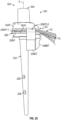
- the segments 154C-1, 154C-2 of the channel 154C, collar passage 154CP and first set of flange passages 156FP-1 can be at least partially aligned along an arc path AP in the installed position (shown in dashed lines).
- the arc path AP can extend at least partially about the longitudinal axis X of the collar portion 154.
- the arc path AP can establish a segment of the securement path SP.
Landscapes
- Health & Medical Sciences (AREA)
- Orthopedic Medicine & Surgery (AREA)
- Cardiology (AREA)
- Oral & Maxillofacial Surgery (AREA)
- Transplantation (AREA)
- Engineering & Computer Science (AREA)
- Biomedical Technology (AREA)
- Heart & Thoracic Surgery (AREA)
- Vascular Medicine (AREA)
- Life Sciences & Earth Sciences (AREA)
- Animal Behavior & Ethology (AREA)
- General Health & Medical Sciences (AREA)
- Public Health (AREA)
- Veterinary Medicine (AREA)
- Prostheses (AREA)
Abstract
Description
- This disclosure relates to orthopaedic procedures and, more particularly, to orthopaedic implant systems and methods for repairing bone defects and restoring functionality to a joint.
- Joints may be established by at least one long bone. The patient may experience loss caused by fracturing or shattering of the bone due to trauma. A prosthesis may be utilized to restore functionality to the bone. The prosthesis may include a stem insertable in a remainder of the bone and may include a head for mounting an articulation member to restore functionality to a joint.
-
US 6 228 120 B1 discloses surgical equipment for implanting a total shoulder prosthesis, and total shoulder prosthesis constituting same.EP 0 679 375 A1 discloses a modular prosthetic assembly for the shoulder joint.WO 03/005933 A2 DE 299 18 589 U1 discloses an endoprosthesis for a shoulder joint.WO 2015/103313 A1 discloses instruments and techniques for orienting prosthesis components for joint prostheses. - This disclosure relates to orthopaedic implant systems and methods for restoring functionality to a joint. The implant systems may include one or more fixation features for securing components of the implant systems to each other and/or adjacent tissue of a patient. The fixation features may include a taper locking mechanism to limit or otherwise oppose separation between components. The fixation features may include one or more flanges adapted to abut an exterior of the bone. The flange may be releasably securable to another component of the implant system and may be securable with one or more flexible constructs.
- An orthopaedic implant system of the present disclosure may include a stem portion insertable into bone and a mounting portion extending from the stem portion. The mounting portion may include a first mounting bore extending inwardly from a first engagement face and a raised protrusion extending outwardly from the first engagement face. The raised protrusion may taper along a declined face toward the first engagement face. A head portion may be adapted to mount an articulation member. The head portion may include a head bore extending inwardly from a second engagement face and a recess extending inwardly from the second engagement face. A periphery of the recess may include an inclined face sloping towards an opening of the recess along the second engagement face. The raised protrusion may be insertable through the opening and into the recess such that the declined face and the inclined face may abut each other in an installed position. The first mounting bore may extend along a first mounting bore axis in a direction away from the raised protrusion such that the inclined face may move towards the first mounting bore axis to compress the inclined face against the declined face in response to securing a common fastener in the head bore and the first mounting bore.
- A method of installing an orthopaedic implant system of the present disclosure may include inserting a stem portion into bone. A mounting portion may be coupled to the stem portion. The mounting portion may include a raised protrusion having a declined face. The method may include coupling a head portion to the mounting portion, which may include positioning the raised protrusion in a recess of the head portion and may include securing a fastener between the head portion and the mounting portion to cause the head portion to move across the mounting portion to compress an inclined face of the recess against the declined face of the raised protrusion.
- An orthopaedic implant system of the present disclosure may include a head portion adapted to mount an articulation member. The articulation member may be configured to mate with an opposed articular surface. A stem portion may be insertable into bone. A collar portion may be adapted to interconnect the head portion and the stem portion. A flange portion may be releasably securable to the collar portion. The flange portion may include a flange body and at least one engagement flange that may be dimensioned to abut bone. The collar portion may include a channel dimensioned to at least partially receive the flange body. The flange portion may be moveable in a direction towards the collar portion to trap a portion of bone between the at least one engagement flange and the stem portion in response to fixing a length of a flexible construct that may couple the collar portion and the flange portion in an installed position.
- A method of installing an orthopaedic implant system of the present disclosure may include inserting a stem portion into an intramedullary canal of a bone. The method may include inserting at least one interface flange of a flange portion into a channel of a collar portion. The collar portion may interconnect the stem portion and a head portion. The head portion may be adapted to mount an articulation member. The flange portion may include at least one engagement flange. The method may include trapping a wall of the bone between the stem portion and the at least one engagement flange in response to fixing a length of a flexible construct coupling the collar portion and the flange portion.
- The present disclosure may include any one or more of the individual features disclosed above and/or below alone or in any combination thereof.
- The various features and advantages of this disclosure will become apparent to those skilled in the art from the following detailed description. The drawings that accompany the detailed description can be briefly described as follows.
-
-
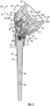
Figure 1 illustrates a perspective view of an exemplary implant system. -
Figure 2 illustrates a perspective view of the implant system adjacent to an articular surface and secured to bone. -
Figure 3 illustrates an exploded view of a mounting portion and head portion of the implant system ofFigure 1 . -
Figure 4 illustrates another exploded view of the mounting portion and head portion ofFigure 3 . -
Figure 5 illustrates a sectional view of the implant system ofFigure 1 . -
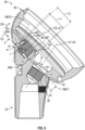
Figure 6 illustrates a sectional view of the mounting portion and head portion ofFigure 1 . -
Figure 7 illustrates a sectional view of the mounting portion taken through line 7-7 ofFigure 6 . -
Figure 8 illustrates an exemplary method of installing an orthopaedic implant system. -
Figure 9 illustrates a side view of the head portion engaging the mounting portion at a first position. -
Figure 10 illustrates a sectional view of the head portion and mounting portion ofFigure 9 . -
Figure 11 illustrates a sectional view of the head portion at an intermediate position relative to the mounting portion. -
Figure 12 illustrates a sectional view of the head portion at a second position relative to the mounting portion. -
Figure 13 illustrates a sectional view of the head portion coupled to the mounting portion at the second position with a fastener. -
Figure 14 illustrates a perspective view of another exemplary implant system. -
Figure 15 illustrates a sectional view of portions of the implant system ofFigure 16 . -
Figure 16 illustrates a sectional view of another exemplary implant system. -
Figure 17 illustrates a perspective view of a support assembly of the implant system ofFigure 14 including a collar portion and a flange portion in an installed position. -
Figure 18 illustrates an exploded view of the collar portion and flange portion ofFigure 17 . -
Figure 19 illustrates a sectional view of the collar portion and flange portion taken along line 19-19 ofFigure 17 . -
Figure 19 illustrates a sectional view of a flexible construct. -
Figure 20 illustrates an exploded view of another support assembly including a collar portion and flange portion. -
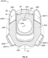
Figure 21 illustrates a sectional view of the collar portion and flange portion ofFigure 20 in an installed position. -
Figure 22 illustrates another exemplary method of installing an orthopaedic implant system including a support assembly. -
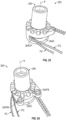
Figures 23 and 24 illustrate perspective views of flexible constructs positioned relative to the collar portion ofFigure 20 . -
Figure 25 illustrates a side view of the implant assembly ofFigure 20 including the flexible constructs positioned relative to the flange portion and the collar portion. -
Figure 26 illustrates a side view of the implant assembly ofFigure 25 situated relative to a bone. -
Figure 27 illustrates another side view of the implant assembly ofFigure 26 including fixing a dimension of each flexible construct. - This disclosure relates to orthopaedic implant systems and methods for repairing bone defects and restoring functionality to various joints. The disclosed implant systems described herein may include a modular prosthesis that may be adapted to facilitate reconstruction or repair of a long bone that may be caused by trauma to the patient. The long bone may have relatively severe proximal bone loss due to fracturing (e.g., 3 part or 4 part fractures) or shattering of the bone due to trauma, or a tumor in the bone, for example. Bone loss may be on the order of approximately one-third of the bone that may indicate a reconstruction procedure. The disclosed implant systems and methods may be utilized to restore functionality to a shoulder joint, including anatomical and reverse shoulder procedures.
- The disclosed implant systems described herein may include a taper locking mechanism to secure adjacent portions of the implant system together in an installed position, such as a head portion and mounting portion of the implant system. The head portion may be adapted to mount an articulation member for mating with an opposed articular surface of a joint. The mounting portion may be coupled to a stem portion insertable into the humerus or other long bone. The taper locking mechanism may be adapted to limit or otherwise oppose separation between the head portion and mounting portion, which may improve healing of the patient.
- The disclosed implant systems may include a flange portion securable to a collar portion or another portion of the implant system. The flange portion may be adapted to abut an exterior of the bone to promote torsional stability when the implant system is placed under torsional loads. The collar portion may be dimensioned to sit on a resected surface or prepared portion of the bone during reconstruction of the bone. The collar portion may be fixedly attached or otherwise secured to a stem portion insertable into the bone. The stem portion may be secured to the bone with one or more bone fasteners distally of the collar portion. One or more flexible constructs may be utilized to secure the flange portion and collar portion to each other at a specified distance to apply a compress force or load on the exterior of the bone, which may promote functionality of the restored joint and healing of the patient. Once a determined compression is achieved, a length or other dimension of the flexible construct and relative position between the collar and flange portions may be fixed. The flexible construct may be a length of suture configured into a loop about the collar and flange portions, for example.
- An orthopaedic implant system of the present disclosure may include a stem portion insertable into bone and a mounting portion extending from the stem portion. The mounting portion may include a first mounting bore extending inwardly from a first engagement face and a raised protrusion extending outwardly from the first engagement face. The raised protrusion may taper along a declined face toward the first engagement face. A head portion may be adapted to mount an articulation member. The head portion may include a head bore extending inwardly from a second engagement face and a recess extending inwardly from the second engagement face. A periphery of the recess may include an inclined face sloping towards an opening of the recess along the second engagement face. The raised protrusion may be insertable through the opening and into the recess such that the declined face and the inclined face may abut each other in an installed position. The first mounting bore may extend along a first mounting bore axis in a direction away from the raised protrusion such that the inclined face may move towards the first mounting bore axis to compress the inclined face against the declined face in response to securing a common fastener in the head bore and the first mounting bore.
- In implementations, the articulation member may be adapted to mate with an opposed articular surface of an adjacent implant or an adjacent bone.
- In implementations, a maximum length of the raised protrusion may be greater than a minimum length of the opening.
- In implementations, the second engagement face of the head portion may slide across the first engagement face in response to rotation of the common fastener about the first mounting bore axis.
- In implementations, the first engagement face of the mounting portion may extend along a first reference plane. The first mounting bore axis may intersect the first reference plane to establish an acute first bore angle. The declined face of the raised protrusion may extend along a second reference plane. The second reference plane may intersect the first reference plane to establish an acute ramp angle. The ramp angle may be less than the first bore angle.
- In implementations, the raised protrusion may include a second mounting bore extending along a second mounting bore axis. The second mounting bore may be dimensioned to receive a fastener to secure an adapter to the mounting portion. The adapter may be adapted to interconnect the head portion and the articulation member.
- In implementations, the second mounting bore axis may intersect the first reference plane to establish a second bore angle. The second bore angle may differ from the first bore angle and may differ from the ramp angle.
- In implementations, the head portion may include a pair of walls interconnecting the inclined face and an arcuate lip to establish the periphery of the recess. The pair of walls may oppose each other on opposite sides of the head bore. The arcuate lip may be opposed to the inclined face and may be dimensioned to follow a perimeter of the head bore. The mounting portion may include a pair of faces on opposite sides of the raised protrusion. The declined face may interconnect the pair of faces. The pair of faces may be dimensioned to engage the respective pair of walls to limit relative movement between the head portion and the mounting portion in the installed position.
- A method of installing an orthopaedic implant system of the present disclosure may include inserting a stem portion into bone. A mounting portion may be coupled to the stem portion. The mounting portion may include a raised protrusion having a declined face. The method may include coupling a head portion to the mounting portion, which may include positioning the raised protrusion in a recess of the head portion and may include securing a fastener between the head portion and the mounting portion to cause the head portion to move across the mounting portion to compress an inclined face of the recess against the declined face of the raised protrusion.
- In implementations, the method may include securing an articulation member to the head portion. The articulation member may be adapted to mate with an opposed articular surface of an adjacent implant or an adjacent bone.
- In implementations, the method may include positioning one or more bone fragments about a periphery of the mounting portion.
- In implementations, the step of securing the fastener may include positioning the fastener through a head bore of the head portion and then into a first mounting bore of the mounting portion. The first mounting bore may extend inwardly from a first engagement face of the mounting portion. The raised protrusion may extend outwardly from the first engagement face. The head bore may extend inwardly from a second engagement face. The step of coupling the head portion to the mounting portion may occur such that the first and second engagement faces abut each other. The first engagement face may extend along a first reference plane. The declined face of the raised protrusion may extend along a second reference plane intersecting the first reference plane to establish an acute ramp angle. The first mounting bore may extend along a first mounting bore axis intersecting the first reference plane to establish an acute first bore angle. The ramp angle may be less than the first bore angle.
- In implementations, the head portion may include an opening to the recess. The opening may be dimensioned to receive the raised protrusion. A maximum length of the raised protrusion may be greater than a minimum length of the opening.
- In implementations, the step of coupling the head portion to the mounting portion may include establishing a pivot point between a periphery of the recess and the declined face, and then pivoting the head portion about the pivot point in a direction towards the mounting portion such that the raised protrusion may pass through the opening and may be captured in the recess.
- An orthopaedic implant system of the present disclosure may include a head portion adapted to mount an articulation member. The articulation member may be configured to mate with an opposed articular surface. A stem portion may be insertable into bone. A collar portion may be adapted to interconnect the head portion and the stem portion. A flange portion may be releasably securable to the collar portion. The flange portion may include a flange body and at least one engagement flange that may be dimensioned to abut bone. The collar portion may include a channel dimensioned to at least partially receive the flange body. The flange portion may be moveable in a direction towards the collar portion to trap a portion of bone between the at least one engagement flange and the stem portion in response to fixing a length of a flexible construct that may couple the collar portion and the flange portion in an installed position.
- In implementations, the flexible construct may be dimensioned to loop about a longitudinal axis of the collar portion in the installed position.
- In implementations, the collar portion may include at least one collar passage dimensioned to receive a respective length of the flexible construct.
- In implementations, the flange body may include one or more flange passages dimensioned to receive a respective length of the flexible construct.
- In implementations, the channel may extend about a periphery of the collar portion. The channel, the at least one collar passage and the one or more flange passages may be at least partially aligned along an arc path in the installed position.
- In implementations, the flexible construct may be dimensioned to loop about the longitudinal axis of the collar portion in the installed position.
- In implementations, the flexible construct may comprise a length of suture.
- In implementations, the flange body may include a first interface flange and a second interface flange insertable into respective portions of the channel.
- In implementations, the first interface flange and the second interface flange may include a respective set of grooves. The collar portion may include a plurality of bores each aligned with a selected groove of the set of grooves in the installed position. A plurality of fasteners may be dimensioned to extend through the respective bores to engage the selected groove to secure the flange portion and the collar portion to each other in the installed position.
- In implementations, the collar portion may include a collar passage interconnecting first and second segments of the channel to establish a securement path.
- In implementations, the at least one engagement flange may include a first engagement flange and a second engagement flange. The flange body may include first and second flange passages that establish the securement path. The first and second flange passages may be established at respective junctions between the flange body and the first and second engagement flanges.
- In implementations, the flange portion may include a third flange passage adjacent a free end of the first interface flange and a fourth flange passage adjacent a free end of the second interface flange. The collar passage may be situated along a segment of the securement path between the third flange passage and the fourth flange passage in the installed position.
- In implementations, the stem portion may include at least one fixation bore spaced apart from the collar portion in the installed position. The at least one fixation bore may be dimensioned to receive a respective bone fastener that may extend through the bone in the installed position.
- A method of installing an orthopaedic implant system of the present disclosure may include inserting a stem portion into an intramedullary canal of a bone. The method may include inserting at least one interface flange of a flange portion into a channel of a collar portion. The collar portion may interconnect the stem portion and a head portion. The head portion may be adapted to mount an articulation member. The flange portion may include at least one engagement flange. The method may include trapping a wall of the bone between the stem portion and the at least one engagement flange in response to fixing a length of a flexible construct coupling the collar portion and the flange portion.
- In implementations, the flexible construct may comprise a length of suture.
- In implementations, the method may include passing the flexible construct through at least one collar passage of the collar portion and through at least one flange passage of the flange portion prior to the fixing step.
- In implementations, the method may include looping the flexible construct around a circumference of the collar portion and through the flange portion, and then tensioning the flexible construct prior to the fixing step.
- In implementations, the stem portion may include at least one fixation bore. The method may include positioning a bone fastener through the at least one fixation bore and into the bone prior to the fixing step.
-
Figures 1 and 2 illustrate an orthopaedic implant system (e.g., assembly) 20. Theimplant system 20 may be utilized in various orthopedic procedures to restore functionality to bones and/or joints such as a shoulder joint during an anatomical or reverse shoulder arthroplasty. Theimplant system 20 may be utilized to restore functionality to one or more bones in a fractured or shattered condition. Theimplant system 20 may be utilized to restore functionality to long bones and other bones such as a humerus or femur. Theimplant system 20 may be utilized to restore functionality to other bones and joints such as a knee, hip, elbow, wrist or ankle. - The
implant system 20 can include one ormore components 21. Thecomponents 21 may be fixedly attached or otherwise secured to each other (see alsoFigure 5 ). In implementations, one or more or each of thecomponents 21 can be integrally formed with each other to establish theimplant system 20. - The
components 21 of theimplant system 20 can include a first (e.g., stem)portion 22, a second (e.g., mounting)portion 24 and a third (e.g., head or cup)portion 26. In the implementation ofFigure 3 , thestem portion 22 can be insertable into bone B (shown in dashed lines). Thestem portion 22 can include one or more fixation bores 28. The fixation bore 28 can be dimensioned to receive a respective fastener F. The fastener F can be dimensioned to extend through the bone B in an installed position to secure thestem portion 22. - The mounting
portion 24 may extend from, and may be coupled to, thestem portion 22 utilizing various techniques. In the implementation ofFigure 5 , the mountingportion 24 may be coupled to thestem portion 22 utilizing aMorse taper connection 27 and/or a fastener 29 such as a locking screw dimensioned to engage a ramped face 31 adjacent a proximal end of thestem portion 22. TheMorse taper connection 27 can serve to limit relative axial and/or rotational movement between thestem portion 22 and mountingportion 24. The fastener 29 may serve to limit relative axial movement between thestem portion 22 and mountingportion 24. Various fasteners may be utilized to secure any of the components of the implant systems disclosed herein, including threaded bolts, pins, rivets, clips, etc. - The
implant system 20 can include an articulation member (e.g., liner) 30. Thearticulation member 30 can have anarticulation surface 30S (Figure 5 ) adapted to mate with an opposed the articular surface AS (Figure 2 ). Thearticulation surface 30S may have a generally concave geometry (see, e.g.,Figure 5 ) or a generally convex geometry (see, e.g.,Figures 14-15 ). The articular surface AS can be established by an adjacent implant or an adjacent bone of an associated joint. The articular surface AS may have a generally convex geometry (e.g.,Figure 2 ) or a generally concave geometry (see, e.g.,Figure 15 ). Thehead portion 26 can be adapted to mount or otherwise secure thearticulation member 30. Thehead portion 26 can interconnect thestem portion 22 and/or mountingportion 24 with thearticulation member 30. - The
implant system 20 may include an adapter (e.g., spacer) 32 adapted to interconnect or otherwise secure thehead portion 26 andarticulation member 30 to each other. Theimplant system 20 may include a set ofadapters 32 of various geometries to space apart and/or orient thehead portion 26 and thearticulation member 30 relative to each other. In other implementations, theadapter 32 can be integrally formed with thehead portion 26 and/orarticulation member 30. In implementations, theadapter 32 may be omitted, and thearticulation member 30 may be mounted or otherwise secured directly to thehead portion 26. - The
implant system 20 can include various features to interact with surrounding bone or other tissue, including one or more surface treatment(s) 37. Thesurface treatments 37 can be established along one or more surfaces of thecomponents 21. Thesurface treatments 37 can include a porous construct or scaffold established in a thickness of thecomponent 21 or can be one or more porous layers of material disposed on a surface of thecomponent 21 to promote fixation with adjacent bone or other tissue. Theimplant system 20 can include one or more passages (e.g., eyelets) 39. Eachpassage 39 can be dimensioned to receive a length of suture to secure bone and/or soft tissue to theimplant system 20. In implementations, thesurface treatments 37 and/orpassages 39 may be omitted. - Referring to
Figures 3 and 4 , with continuing reference toFigures 1 and 2 , theimplant system 20 can include one or more features adapted to secure thecomponents 21 to each other, such as the mountingportion 24 andhead portion 26. The mountingportion 24 can include a first engagement surface (e.g., face) 34, a first mounting bore 36 (Figure 4 ) and a raised protrusion (e.g., boss) 38. Thefirst engagement face 34 can be generally or substantially planar. For the purposes of this disclosure, the terms "about," "approximately" and "substantially" mean ± 10 percent of the stated value or relationship unless otherwise stated. The first mounting bore 36 may be dimensioned to extend inwardly from thefirst engagement face 34 of the mountingportion 24. - The raised
protrusion 38 may extend outwardly from thefirst engagement face 34 of the mountingportion 24. The raisedprotrusion 38 may be spaced apart from the first mounting bore 36 relative to thefirst engagement face 34. The raisedprotrusion 38 may include a second mounting bore 40 (Figure 4 ). The second mounting bore 40 may be established along a proximal face 38P of the raisedprotrusion 38. The proximal face 38P may extend along a free end of the raisedprotrusion 38. In other implementations, the second mounting bore 40 may be omitted. - The
head portion 26 may include a second engagement surface (e.g., face) 42 for engaging thefirst engagement face 34. Thesecond engagement face 42 can be generally or substantially planar. Thefirst engagement face 34 andsecond engagement face 42 may be dimensioned to mate with or otherwise contact each other to establish an engagement interface EI between thefirst engagement face 34 andsecond engagement face 42 in the installed position, as illustrated inFigure 5 . Thesecond engagement face 42 may be dimensioned to sit on thefirst engagement face 34 in the installed position. - The
head portion 26 may include a head bore 44 and arecess 46, as illustrated inFigure 3 . The head bore 44 andrecess 46 may be spaced apart from each other relative to thesecond engagement face 42 of thehead portion 26. The head bore 44 andrecess 46 may be dimensioned to extend inwardly from thesecond engagement face 42. Theadapter 32 may be dimensioned to at least partially or completely block an opening (e.g., entrance) 44E of the head bore 44 in the installed position (see, e.g.,Figure 5 ). - Referring to
Figure 5 , with continuing reference toFigures 3 and 4 , the first mounting bore 36 can be dimensioned to extend along a first mounting bore axis A1. The second mounting bore 40 of the raisedprotrusion 38 can be dimensioned to extend along a second mounting bore axis A2. A longitudinal axis LA of the raisedprotrusion 38 may coincide with, or may otherwise be substantially parallel to, the second mounting bore axis A2 of the second mounting bore 40. In other implementations, the second mounting bore axis A2 and longitudinal axis LA of the raisedprotrusion 38 may be transverse to each other. The head bore 44 of thehead portion 26 can be dimensioned to extend along a head bore axis A3. - The first mounting bore 36 and the head bore 44 can be dimensioned to receive a first (e.g., common) fastener F1 to secure the mounting
portion 24 andhead portion 26 to each other in the installed position. In implementations, the first mounting bore axis A1 of the first mounting bore 36 and head bore axis A3 of the head bore 44 can be substantially aligned with each other along engagement interface EI to receive the fastener F1 in the installed position. - The
adapter 32 can include an adapter (e.g., spacer) bore 48 for securing theadapter 32 and mountingportion 24 to each other. Thehead portion 26 can include a second head bore 45 (see alsoFigure 3 ). The second mounting bore 40, second head bore 45 and adapter bore 48 can be dimensioned to receive a second (e.g., common) fastener F2 in the installed position. The second mounting bore 40, second head bore 45 and adapter bore 48 may be substantially aligned with each other along the second mounting bore axis A2 to receive the common fastener F2 to secure theadapter 32 and mountingportion 24 to each other in the installed position. In implementations, the fastener F2 may be secured in the second mounting bore 40, second head bore 45 and adapter bore 48 subsequent to securing the fastener F1 in the first mounting bore 36 and head bore 44. The axis A2 of the second mounting bore 40 and an axis of the second head bore 45 may be misaligned prior to securing the fastener F1 (see, e.g.,Figure 10 ) and may be substantially aligned in response to securing the fastener F1 (see, e.g.,Figure 13 ). - Referring to
Figure 6 , with continuing reference toFigures 3-5 , theimplant system 20 can include one or more fixation features to lock or otherwise secure the mountingportion 24 andhead portion 26 to each other. The fixation may be established under a compressive load or force in a non-perpendicular direction relative to thefirst engagement face 34. Thefirst engagement face 34 of the mountingportion 24 can be dimensioned to extend along a first reference plane REF1 (shown in dashed lines). The raisedprotrusion 38 can be dimensioned to extend outwardly (e.g., proximally) from the first reference plane REF1. - The mounting
portion 24 andhead portion 26 may cooperate to establish a taper locking mechanism for improving fixation of thehead portion 26. The raisedprotrusion 38 of the mountingportion 24 and therecess 46 of thehead portion 26 may be dimensioned to establish the taper locking mechanism. The raisedprotrusion 38 can include a first (e.g., declined)face 38D dimensioned to contact thehead portion 26. The declinedface 38D may be established along a periphery of the raisedprotrusion 38. The raisedprotrusion 38 may be dimensioned to taper along the declinedface 38D from a proximal face (e.g., free end) 38P of the raisedprotrusion 38 toward thefirst engagement face 34 and/or first reference plane REF1 such that a cross-sectional area of the raisedprotrusion 38 decreases in a direction from the proximal face 38P towards the first reference plane REF1 to establish a generally wedge-shapedengagement recess 41. The raisedprotrusion 38 may be dimensioned to flare outwardly from thefirst engagement face 34 and/or first reference plane REF1 such that the cross-sectional area of the raisedprotrusion 38 increases in a direction away from the first reference plane REF1 towards the proximal face 38P of the raisedprotrusion 38. The declinedface 38D may be generally or substantially planar. The declinedface 38D may extend along a second reference plane REF2 (shown in dashed lines). The declinedface 38D of the raisedprotrusion 38 can be dimensioned such that the second reference plane REF2 intersects the first reference plane REF1 to establish a ramp angle α. In implementations, the ramp angle α may be an acute angle. The ramp angle α may be less than 90 degrees and/or greater than or equal to 45 degrees. In other implementations, the ramp angle α is greater than or equal to 90 degrees. - The first mounting bore axis A1 may be dimensioned to intersect the first reference plane REF1 to establish a first bore angle β. In implementations, the first bore angle β may be an acute angle. The first bore angle β may be less than 90 degrees and/or greater than or equal to 45 degrees. In implementations, the first bore angle β is greater than or equal to 70 degrees, such as approximately 80 degrees. The ramp angle α may be less than or equal to the first bore angle β relative to the first reference plane REF1. In other implementations, the ramp angle α may be greater than the first bore angle β.
- The
head portion 26 can include a second (e.g., inclined) face 46F dimensioned to engage the declinedface 38D of the raisedprotrusion 38 in the installed position. Theinclined face 46F may be established by a wall of thehead portion 26. In implementations, theinclined face 46F can extend along and bound aperiphery 46P of therecess 46. Thehead portion 26 can include a generally-wedge shapedengagement lip 47 that may establish a portion of theperiphery 46P of therecess 46. Theinclined face 46F may be dimensioned to slope along theengagement lip 47 towards an opening (e.g., entrance) 46E of therecess 46 along thesecond engagement face 42. Theengagement lip 47 may be dimensioned to be at least partially received in theengagement recess 41. In implementations, theengagement recess 41 is dimensioned to substantially follow a contour of theengagement lip 47 such that theengagement lip 47 is wedged against the declinedface 38D in the installed position. - The raised
protrusion 38 may be insertable through theopening 46E and into therecess 46 such that the declinedface 38D and theinclined face 46F abut each other to establish a ramped interface RI in the installed position. The ramped interface RI may be separate and distinct from the engagement interface EI. - The raised
protrusion 38 and therecess 46 of thehead portion 26 can be dimensioned such that theinclined face 46F binds or compresses against the declinedface 38D in response to at least partially or completely securing the fastener F1 in the first mounting bore 36 and the head bore 44, as illustrated inFigure 5 . The first mounting bore 36 may be dimensioned to extend along the first mounting bore axis A1 in a direction away from the raisedprotrusion 38 such that theinclined face 46F moves in a first direction D1 (e.g., sideways) towards the first mounting bore axis A1 to cause theinclined face 46F to bind or compress against the declinedface 38D in response to securing the common fastener F1 in the first mounting bore 36 and head bore 44. In implementations, the ramp angle α can be less than the first bore angle β such that theinclined face 46F moves in the first direction D1 towards the first mounting bore axis A1 to bind or compress theinclined face 46F against the declinedface 38D in response to securing the common fastener F1. In implementations, thesecond engagement face 42 of thehead portion 26 can be dimensioned to slide in the first direction D1 across thefirst engagement face 34 in response to rotation of the common fastener F1 in a rotational direction R1 about the first mounting bore axis A1 such that the common fastener F1 translates along the first mounting bore axis A1, as illustrated inFigure 5 . The acute ramp angle α can serve to cause the raisedprotrusion 38 to oppose movement of thehead portion 26 in a second direction D2 (Figure 5 ) away from the first reference plane REF1 in the installed position. In implementations, the first direction D1 may be substantially perpendicular or otherwise transverse to the second mounting bore axis A2 of the second mounting bore 40. The first direction D1 may be substantially parallel to the first reference plane REF1 and/or oblique to the first mounting bore axis A1 of the first mounting bore 36. The second direction D2 can be substantially perpendicular to the first direction D1,first engagement face 34 and/or first reference plane REF1. - The second mounting bore 40 can be dimensioned relative to the first mounting bore 36 and/or declined
face 38D to improve fixation of thehead portion 26. The second mounting bore axis A2 of the second mounting bore 40 can be dimensioned to intersect the first reference plane REF1 to establish a second bore angle γ. The second bore angle γ may be the same, or may differ from, the ramp angle α and/or first bore angle β. In implementations, the second bore angle γ differs from both the ramp angle α and first bore angle β. The second mounting bore 40 may be dimensioned such that second bore angle γ can be substantially perpendicular to the first reference plane REF1. - Referring to
Figure 7 , with continuing reference toFigures 3-4 and6 , the raisedprotrusion 38 andrecess 46 can be dimensioned to limit relative movement between the mountingportion 24 andhead portion 26 with respect to the first reference plane REF1. Thehead portion 26 can include a pair ofwalls 46W interconnecting theinclined face 46F and anarcuate lip 46L to establish theperiphery 46P of therecess 46. The pair ofwalls 46W can be dimensioned to oppose each other on opposite sides of the head bore 44. Thewalls 46W can be substantially planar. Thewalls 46W can be substantially parallel or transverse to each other. Thearcuate lip 46L can be dimensioned to extend towards and be opposed to theinclined face 46F. Thearcuate lip 46L can be dimensioned to follow a perimeter 44P of the head bore 44. Thewalls 46W,inclined face 46F andarcuate lip 46L may cooperate to establish theentrance 46E of therecess 46. - The raised
protrusion 38 can include arecess 38R dimensioned to at least partially receive thearcuate lip 46L. The declinedface 38D andrecess 38R can be established on opposite sides of the raisedprotrusion 38. A periphery of therecess 38R can be dimensioned to substantially follow a contour of thearcuate lip 46L. The raisedprotrusion 38 can be dimensioned such that the periphery of therecess 38R is spaced apart from thearcuate lip 46L in response to movement of thehead portion 26 in the first direction D1, as illustrated inFigure 5 . - The mounting
portion 24 can include a pair of faces (e.g., abutments) 38F. The declinedface 38D of the raisedprotrusion 38 can be dimensioned to interconnect thefaces 38F. The faces 38F can be dimensioned to be on opposite sides of the raisedprotrusion 38. The faces 38F can be substantially planar. The faces 38F can be substantially parallel or transverse to each other. Thewalls 46W of therecess 46 can be dimensioned to substantially follow a geometry of the respective faces 38F. The faces 38F can be dimensioned to engage therespective walls 46W of therecess 46 to limit relative movement between thehead portion 26 and the mountingportion 24 in the installed position. - The
entrance 46E of therecess 46 can be dimensioned to capture the raisedprotrusion 38 in therecess 46 to limit movement of thehead portion 26 in the second direction D2 (Figure 5 ) away from the mountingportion 24 in the installed position. Theentrance 46E may be dimensioned to block insertion of the raisedprotrusion 38 into therecess 46 in response to movement of thehead portion 26 in a direction substantially parallel to the longitudinal axis LA of the raisedprotrusion 38. A thickness of the raisedprotrusion 38 may be dimensioned to taper in a direction from the proximal face 38P towards thefirst engagement face 34 to facilitate insertion of the raisedprotrusion 38 through theentrance 46E at an oblique angle. A maximum (e.g., first) length L1 may be established across the raised protrusion 38 (Figure 6 ). The maximum length L1 may be established by the proximal face 38P of the raisedprotrusion 38. A minimum (e.g., second) length L2 may be established across theentrance 46E of the recess 46R (Figures 6-7 ). The maximum length L1 of the raisedprotrusion 38 can be greater than the minimum length L2 of theentrance 46E of the recess 46R to capture thehead portion 26. Therecess 46 can be dimensioned such that thehead portion 26 is pivotable about the raisedprotrusion 38 to capture the raisedprotrusion 38 at least partially or substantially in therecess 46 in the installed position. -
Figure 8 illustrates a method of installing an orthopedic implant system inflow chart 50 according to implementation. Themethod 50 may be utilized to perform an arthroplasty to restore functionality to a bone and/or joint, including any of the bones and joints disclosed herein. In implementations, the method 60 can be utilized in repair of a fractured proximal humerus. Themethod 50 may be utilized in an anatomical shoulder or reverse shoulder arthroplasty. Themethod 50 can be utilized in accordance with any of the implant systems disclosed herein, including theimplant system 20. Reference is made to theimplant system 20 for illustrative purposes. Fewer or additional steps than are recited below could be performed within the scope of this disclosure, and the recited order of steps is not intended to limit this disclosure. - The disclosed implant systems may be provided to the surgeon as a kit. The kit may include components of various shapes and sizes. The particular components may be selected from the kit to establish a specified configuration of the implant system according to an anatomy of the patient and other aspects of a surgical plan.
- Referring to
Figure 2 , with continuing reference toFigure 8 , atstep 50A thestem portion 22 can be at least partially inserted into a recess of a bone B, such as an intramedullary canal IC. Thestem portion 22 and mountingportion 24 can be coupled to each other atstep 50B. In other implementations, thestem portion 22 and mountingportion 24 are integrally formed with each other and step 50B can be omitted. - At
step 50C, the mountingportion 24 andhead portion 26 can be coupled to each other. Referring toFigure 9 , with continuing reference toFigure 8 ,step 50C can include positioning the raisedprotrusion 38 at least partially in therecess 46 of thehead portion 26.Step 50C can include positioning the raisedprotrusion 38 in therecess 46 of thehead portion 26 atstep 50C-1. Coupling the mountingportion 24 andhead portion 26 to each other atstep 50C can occur such that thefirst engagement face 34 andsecond engagement face 42 abut each other in the installed position. In implementations, thecomponents 21 of theimplant system 20 are assembled together prior to situating thestem portion 22 in the bone B atstep 50A, including thestem portion 22, mountingportion 24 andhead portion 26. - Referring to
Figure 9 , with continuing reference toFigures 5-6 and8 , step 50C-1 can include establishing a pivot (e.g., hinge) point P1 between theperiphery 46P of therecess 46 and the declinedface 38D of the raisedprotrusion 38 at a first position. Referring toFigures 10-11 , with continuing reference toFigures 5-6 and8-9 , step 50C-1 can include progressively pivoting thehead portion 26 in a rotational direction R2 about the pivot point P1 towards the mountingportion 24 such that the raisedprotrusion 38 passes through theentrance 46E and is at least partially captured in therecess 46.Step 50C-1 can include causing the pivot point P1 to slide or otherwise move along the declinedface 38D in a direction towards thefirst engagement face 34 during the pivoting of thehead portion 26. Movement of the pivot point P1 along the declinedface 38D can establish a ramping action between the declinedface 38D andinclined face 46F. - Referring to
Figure 12 , with continuing reference toFigure 8 , thehead portion 26 can be pivoted in the rotational direction R2 about the pivot point P1 such that thefirst engagement face 34 and thesecond engagement face 42 abut against each other in a second position. The axis A3 of the head bore 44 may be misaligned with the axis A1 of the first mounting bore 36 during the pivoting of thehead portion 26 in the rotational direction R1 (see, e.g.,Figures 10-11 ) until thefirst engagement face 34 and thesecond engagement face 42 abut against each other in the second position. The axis A3 of the head bore 44 may be substantially aligned with the axis A1 of the first mounting bore 36 in the second position. Thesecond engagement face 42 of thehead portion 26 may be seated on thefirst engagement face 34 of the mountingportion 24 in the second position. - Referring to
Figure 13 , with continuing reference toFigure 8 ,step 50C can include securing the fastener F1 between the mountingportion 24 andhead portion 26 to each other with the fastener F1 atstep 50C-2. Securing the fastener F1 can include positioning the fastener F1 through the head bore 44 and then into the first mounting bore 36 of the mountingportion 24.Step 50C-2 can include rotating the fastener F1 in the rotational direction R1 about the first mounting bore axis A1 of the first mounting bore 36 to thread the fastener F1 into the first mounting bore 36. Securing the mountingportion 24 andhead portion 26 with the fastener F1 can cause thehead portion 26 to move in the direction D1 across the mountingportion 24 to bind or compress theinclined face 46F of therecess 46 against the declinedface 38D of the raisedprotrusion 38 to lock the mountingportion 24 andhead portion 26 to each other in the installed position. Securing the fastener F1 can occur such that theinclined face 46F of thehead portion 26 applies a compressive force (e.g., load) CF against the declinedface 38D of the raisedprotrusion 38 along the ramped interface RI. The compressive force CF may have a major component in a direction that is substantially perpendicular to the longitudinal axis LA of the raised protrusion 38 (see alsoFigures 5-7 ). The compressive force CF may be substantially parallel to thedirection D 1. -
Method 50 can include one or more additional steps to install theimplant system 20 at the surgical site. Referring toFigures 2 and5 , with continuing reference toFigure 8 , atstep 50D a selectedadapter 32 can be secured to thehead portion 26. Atstep 50E, a selectedarticulation member 30 can be secured to thehead portion 26.Step 50E can include securing thearticulation member 30 to theadapter 32 such that theadapter 32 interconnects thehead portion 26 andarticulation member 30. In implementations, thearticulation member 30 is secured directly to thehead portion 26 andstep 50D is omitted. Thearticulation member 30 can be positioned to mate with an opposed articular surface AS of an adjacent implant or an adjacent bone, as illustrated inFigure 2 .Method 50 can include positioning one or more bone fragments BF about a periphery of the mountingportion 24 and/or stemportion 22 atstep 50F (bone fragments BF shown in dashed lines inFigure 2 for illustrative purposes). - Referring to
Figure 14 , anorthopedic implant system 120 is disclosed. Theimplant system 120 may be utilized in various orthopedic procedures to restore functionality to a bone and/or joint, such as a shoulder joint during an anatomical or reverse shoulder arthroplasty. Theimplant system 120 may be utilized to restore functionality to one or more bones in a fractured or shattered condition. Theimplant system 120 may be utilized to restore functionality to long bones and other bones such as a humerus or femur. Theimplant system 20 may be utilized to restore functionality to other bones and joints such as a knee, hip, elbow, wrist or ankle. Theimplant system 120 can incorporate any of the features disclosed herein including any of thecomponents 21 and other features of theimplant system 20, and vice versa. In this disclosure, like reference numerals designate like elements where appropriate and reference numerals with the addition of one-hundred or multiples thereof designate modified elements that are understood to incorporate the same features and benefits of the corresponding original elements. - The
implant system 120 can include one ormore components 121. Thecomponents 121 may be fixedly attached or otherwise secured to each other. In implementations, one or more or each of thecomponents 121 can be integrally formed with each other to establish theimplant system 120. - The
components 121 of theimplant system 120 can include astem portion 122 andhead portion 126. Thestem portion 122 can be insertable into bone. Thehead portion 126 can be adapted to mount anarticulation member 130. Thearticulation member 130 can be configured to mate with an opposed articular surface, including any of the articular surfaces disclosed herein. Articular surface AS is shown in dashed lines inFigure 15 for illustrative purposes. Thecomponents 121 can include at least one adapter (e.g., spacer) 132, as illustrated inFigure 15 . The adapter 132 can be dimensioned to interconnect thehead portion 126 andarticulation member 130. In implementations, the adapter 132 is omitted, and thearticulation member 130 is coupled directly to thehead portion 126. - The
implant system 120 can include one or moreintermediate portions 152. Each of theintermediate portions 152 can be adapted to interconnect thestem portion 122 andhead portion 126. In implementations, the one or more of theintermediate portions 152 may be integrally formed with thestem portion 122. In other implementations, theimplant system 120 may be configured such that one or more of theintermediate portions 152 may be omitted (see, e.g., implant system 120' ofFigure 16 ). In implementations, theintermediate portions 152 are omitted (see, e.g.,implant system 20 ofFigure 1 ). Theintermediate portions 152 can be provided to the surgeon in a kit to set a specified distance between thestem portion 122 andhead portion 126. - Various techniques can be utilized to interconnect the
components 121. Thecomponents 121 can include one or moreMorse taper connections 127 dimensioned to limit relative axial and/or rotational movement between the components 121 (see, e.g.,Figures 15-16 ). In implementations, thecomponents 121 can include one or more sets ofteeth 133 adapted to interlock or mesh with a set ofteeth 133 of an adjacent one of thecomponents 121. The interlockingteeth 133 can be dimensioned to limit relative rotation between therespective components 121. In implementations, thecomponents 121 can be fixedly attached or otherwise secured to each other utilizing one or more fasteners. - Referring to
Figures 17 and18 , with continuing reference toFigure 14 , theimplant system 120 can include asupport assembly 153 for supporting theimplant system 120 relative to bone or other tissue. Thesupport assembly 153 can be adapted to support a proximal end portion ofstem portion 122 when thestem portion 122 is situated in bone at a surgical site. - The
support assembly 153 can include acollar portion 154 andflange portion 156. Theflange portion 156 can be releasably secured to thecollar portion 154. Thecollar portion 154 can be adapted to interconnect thehead portion 126 and stem portion 122 (see, e.g.,Figure 14 ). Theflange portion 156 may be adapted to cooperate with thecollar portion 154 to apply a compressive force or load on an adjacent bone for reacting torsional loads that may be experienced by thestem portion 122 and/or other portions of theimplant system 120 when implanted in the patient. - The
stem portion 122 can include at least one or more fixation bores 128 (see alsoFigures 1-2 and5 ). Each fixation bore 128 can be spaced apart from thecollar portion 154 in the installed position. Each fixation bore 128 can be dimensioned to receive a respective bone fastener, which can be dimensioned to extend through the bone to fix a position of thestem portion 122 relative to the bone in the installed position (see, e.g., thestem portion 22 ofFigure 2 ). - The
collar portion 154 can include acollar body 154A having acollar bore 154B andchannel 154C. The collar bore 154B can be dimensioned to extend along a longitudinal axis X of thecollar portion 154. The collar bore 154B can be dimensioned to receive an end 122E of the stem portion 122 (shown inFigure 19 in dashed lines for illustrative purposes). Thecollar portion 154 can be fixedly attached or otherwise secured to the end 122E of thestem portion 122 with a fastener FC (Figure 17 , see alsoFigure 16 ). Thechannel 154C can be dimensioned to receive theflange portion 156 to secure theflange portion 156 to the stem portion 122 (Figure 17 ). Thechannel 154C can be established along, or otherwise at least partially in, thebody 154A. Thechannel 154C can extend at least partially about a periphery (e.g., circumference) 154P of thecollar portion 154. In implementation ofFigure 19 , thechannel 154C is dimensioned to extend substantially or completely about the longitudinal axis X of the collar portion 154 (see alsoFigure 18 ). - The
flange portion 156 can include aflange body 156A and at least one or more engagement flanges 156EF. Each engagement flange 156EF can be dimensioned to extend outwardly from theflange body 156A. Each engagement flange 156EF can be dimensioned to abut bone or other tissue in the installed position. In the implementation ofFigures 17-18 , theflange portion 156 can include first and second engagement flanges 156EF-1, 156EF-2. It should be understood that fewer or more than twoengagement flanges 156 may be utilized, such as only one or three ormore engagement flanges 156. - The engagement flanges 156EF can be arranged at various orientations relative to the
flange body 156A. In implementations, the engagement flanges 156EF can be substantially parallel to each other. The engagement flanges 156EF can be circumferentially offset less than 180 degrees, or more narrowly less than or equal to about 120 degrees and/or greater than or equal to 90 degrees, relative to the longitudinal axis X of thecollar portion 154 in the installed position. - Each engagement flange 156EF can include at least one
engagement face 157. The engagement face 159 can be dimensioned to contact bone or other tissue, such as a cortical wall of a long bone (see, e.g., engagement faces 257 ofFigure 27 ). One ormore surface treatments 137 can be disposed along the engagement flange 156EF to establish therespective engagement face 157 for promoting fixation with adjacent bone or other tissue (see, e.g.,surface treatments 237 shown in dashed lines inFigure 27 ). Thesurface treatments 137 can include any of the treatments disclosed herein, such as a porous construct or scaffold established in a thickness of the engagement flange 156EF or one or more porous layers of material disposed on the engagement flange 156EF. - The
channel 154C of thecollar portion 154 can be dimensioned to at least partially receive theflange body 156A. Theflange body 156A can include one or more interface flanges 156IF. In the implementation ofFigures 17-18 , theflange portion 156 includes a set of (e.g., first and second) interface flanges 156IF-1, 156IF-2. The interface flanges 156IF can be dimensioned to be at least partially inserted into respective portions of thechannel 154C to secure theflange portion 156 to the collar portion 154 (see alsoFigure 19 ). Theflange body 156A can include abridge 156B that interconnects the interface flanges 156IF-1, 156IF-2 and engagement flanges 156EF-1, 156EF-2. Theflange body 156A and interface flanges 156IF-1, 156IF-2 can cooperate to establish a generally U-shaped geometry. In implementation ofFigure 19 , the interface flanges 156IF-1, 156IF-2 can be situated in thechannel 154C on opposite sides of the longitudinal axis X of thecollar portion 154 in the installed position. The interface flanges 156IF can be arranged at various orientations relative to theflange body 156A. In implementations, the interface flanges 156IF can be substantially parallel to each other. The pair of interface flanges 156IF can be substantially perpendicular to the pair of engagement flanges 156EF. - The
support assembly 153 can include one or more features to secure thecollar portion 154 andflange portion 156 to each other once a length or other dimension of the flexible construct FC is set. Each of the interface flanges 156IF can include a respective set ofgrooves 156G (Figure 18 ). Thecollar portion 154 can include one or more fixation bores 154FB. Each fixation bore 154FB can extend along a respective bore axis BA. The fixation bore 154FB can be dimensioned such that a projection of the bore axis BA intersects thechannel 154C, as illustrated inFigure 18 . Each of the fixation bores 154FB can be aligned with a selectedgroove 156G of the set ofgrooves 156G in the installed position. Thesupport assembly 153 can include one or more fasteners F dimensioned to extend through the respective fixation bores 154FB to engage the selectedgroove 156G to secure theflange portion 156 and thecollar portion 154 to each other in the installed position. - The
support assembly 153 can include one or more features to fix or otherwise set a distance between theflange portion 156 and the longitudinal axis X of thecollar portion 154. In the implementation ofFigure 19 , thecollar portion 154 andflange portion 156 can be secured or coupled to each other with at least one flexible construct FC (shown in dashed lines for illustrative purposes). Thesupport assembly 153 can cooperate with the flexible construct(s) FC to fix or otherwise set the distance between theflange portion 156 and the longitudinal axis X of thecollar portion 154. In implementations, thesupport assembly 153 can cooperate with more than one flexible construct FC to fix or otherwise set the distance between theflange portion 156 and thecollar portion 154. Theflange portion 156 can be movable in a third direction D3 toward thecollar portion 154 to trap a portion of bone between the engagement flanges 156EF and thestem portion 122 in response to fixing a length of the flexible construct FC in the installed position (see, e.g.,stem portion 222 andsupport assembly 253 ofFigure 27 ). - Various arrangements and materials can be utilized to establish the flexible construct FC. The flexible construct FC may comprise metallic and/or non-metallic materials, including inorganic and/or organic materials, and combinations thereof. The flexible construct FC may be established by a wire, chain, band, cable, rope, cord, suture, tape, filaments, yarns, adjustable knotless suture/button constructs, etc. The material may be reshapable and may rebound or may be permanently deformable. In the implementation of
Figure 19A , the flexible construct FC may include a length of suture having one or more filaments F. The filaments F can be continuous or discontinuous. The filaments F can be braided or twisted together to establish a length of the flexible construct FC. The flexible construct FC may be continuous or may have a discreet pair of ends securable to each other utilizing a knot or other fixation technique. The flexible construct FC may be a tensionable loop dimensioned to establish a loop about the longitudinal axis X of thecollar portion 154 in the installed position. The flexible construct FC can be tied in a knot to form a loop (see, e.g.,Figure 27 ). In implementations, one or more knots can be formed at specified positions along the length of flexible construct FC, with the knots drawn against thecollar portion 154 and/orflange portion 156 to set the specified length or dimension of the flexible construct FC. - Referring to
Figure 19 , with continuing reference toFigures 17 and18 , thecollar portion 154 andflange portion 156 can cooperate to establish a securement path SP (shown in dashed lines for illustrative purposes). The securement path SP can be dimensioned to extend at least partially, substantially or completely about the longitudinal axis X of thecollar portion 154. The securement path SP can generally form a loop about the longitudinal axis X of thecollar portion 154. In other implementations, the securement path SP extends only partially about the longitudinal axis X of thecollar portion 154. In yet other implementations, the securement path SP may be substantially linear and may extend between a pair of discrete ends. - The securement path SP can be dimensioned to receive at least a portion of the flexible construct FC. The flexible construct FC can be situated along at least one or more segments of the securement path SP. The flexible construct FC can be situated at least partially, substantially or completely along an entire length of the securement path SP. In other implementations, the flexible construct FC extends along only one or more segments of the securement path SP such that the flexible construct FC may extend along less than the entire length of the securement path SP. The securement path SP can be continuous or can include one or more discontinuous segments.
- The
collar portion 154 and/orflange portion 156 can include one or more features for capturing each flexible construct FC along the respective the securement path SP. Thechannel 154C can establish one or more segments of the securement path SP, as illustrated by first andsecond channel segments 154C-1, 154C-2. Thecollar portion 154 can include at least one collar passage 154CP. The collar passage 154CP can be established along, and may enclose, a portion of thechannel 154C. The collar passage 154CP can be dimensioned to interconnect thechannel segments 154C-1, 154C-2 to establish the securement path SP. - The
flange portion 156 can include one or more flange passages 156FP. The flange passages 156FP may establish respective portions of the securement path SP. The flange passages 156FP,channel 154C and/or collar passage 154CP can cooperate to establish respective segments of the securement path SP in the installed position. - The flange passages 156FP can be established along various portions of the
flange portion 156. In the implementation ofFigure 19 , theflange body 156A can include a first set (e.g., pair) of flange passages 156FP-1 and a second set (e.g., pair) of flange passages 156FP-2. The first set of flange passages 156FP-1 can be established along, or can otherwise be adjacent to, free ends 156E of the respective interface flanges 156IF. In the implementation ofFigures 20 and21 , a first set of flange passages 256FP-1 can be dimensioned to extend inwardly fromfree ends 256E of the respective interface flanges 256IF. The flange passages 256FP-1 may be open at the free ends 256E of the interface flanges 256IF such that the free ends 256E have a generally C-shaped geometry. The collar passage 254CP may be situated along a segment of the securement path SP between the pair of flange passages 156FP-1 in the installed position, as illustrated inFigure 21 . - Referring to
Figure 19 , with continuing reference toFigures 17 and18 , the second set of flange passages 156FP-2 can be established along a segment passing through theflange body 156A between the first set of flange passages 156FP-1 relative to the securement path SP. The flange passages 156FP-2 can be established between the first set of flange passages 156F-1 and the engagement flanges 156EF. The flange passages 156FP-2 can be at least partially aligned with the respective engagement flanges 156EF. The flange passages 156FP-2 can be established at respective junctions between theflange body 156A and the respective engagement flanges 156EF-1, 156EF-2. - The first and
second segments 154C-1, 154C-2 of thechannel 154C and the respective flange passages 156FP-1 of the interface flanges 156IF can be at least partially aligned with each other in the installed position. Thesegments 154C-1, 154C-2 of thechannel 154C, collar passage 154CP and flange passages 156FP can be substantially aligned with respect to each other relative to a reference plane that is perpendicular or otherwise transverse to the longitudinal axis X of thecollar portion 154 in the installed position. Thesegments 154C-1, 154C-2 of thechannel 154C, collar passage 154CP and first set of flange passages 156FP-1 can be at least partially aligned along an arc path AP in the installed position (shown in dashed lines). The arc path AP can extend at least partially about the longitudinal axis X of thecollar portion 154. The arc path AP can establish a segment of the securement path SP. -
Figure 22 illustrates a method of installing an orthopedic implant system in aflow chart 260 according to implementation. Themethod 260 can be utilized in an orthopedic procedure to restore functionality to a bone and/or joint, including any of the bones and joints disclosed herein. In implementations, themethod 260 can be utilized in repair of a fractured or shattered proximal humerus or other long bone. Themethod 260 may be utilized in an anatomical shoulder or reverse shoulder arthroplasty. Themethod 260 can be utilized with any of the implant systems disclosed herein, includingimplant systems implant system 220 for illustrative purposes. Fewer or additional steps than are recited below could be performed within the scope of this disclosure, and the recited order of steps is not intended to limit this disclosure. - Referring to
Figures 23 and 24 , with continuing reference toFigure 22 , one or more flexible constructs FC can be positioned relative to thecollar portion 254 and/orflange portion 256 atstep 260A (see, e.g.,Figure 25 ).Step 260A may include looping the flexible construct FC about thecollar portion 254 andflange portion 256.Step 260A can include passing one or more of the flexible constructs FC through the collar passage 254CP (Figure 23 ) such that the flexible construct FC loops about the longitudinal axis X of thecollar portion 254. At least a portion of each flexible construct FC can be positioned along a segment of thechannel 254C. Referring toFigure 25 , with continuing reference toFigure 22 , a portion of each flexible construct FC can be positioned through one or more of the flange passages 256FP of theflange portion 256.Step 260A can include positioning each flexible construct FC through each of the first set of flange passages 256FP-1 and/or the second set of flanges passage 256FP-2 (shown in dashed lines for illustrative purposes). - At
step 260B, theflange portion 256 can be secured to thecollar portion 254.Step 260B can include moving theflange portion 256 in a third direction D3 towards the longitudinal axis X of thecollar portion 254 and into abutment with thecollar portion 254 such that each interface flange 256IF is at least partially received along a portion of thechannel 254C.Step 260B can include at least partially inserting at least one or more interface flanges 254IF of theflange portion 256 into thechannel 254C of thecollar portion 254 in response to moving theflange portion 256 in the direction D3. Positioning the flexible construct FC atstep 260A can be performed prior to, during, and/or subsequent to securing thecollar portion 254 andflange portion 256 to each other atstep 260B.Step 260A can include passing each flexible construct FC through at least one collar passage 254CP of thecollar portion 254 and through at least one or more of the flange passages 256FP of theflange portion 256 prior to fixing a specified length of the flexible construct FC. - Referring to
Figure 25 , with continued reference toFigure 22 , thecollar portion 254 andstem portion 222 can be secured to each other atstep 260C utilizing any of the techniques disclosed herein. Referring toFigure 26 , with continuing reference toFigures 22 and25 , thestem portion 222 can be inserted into bone B atstep 260D (stemportion 222 shown in dashed lines).Step 260D can include moving the stem portion in a fourth direction D4 such that at least a portion of thestem portion 222 is inserted into an intramedullary canal IC of the bone B (shown in dashed lines). The bone B may be any of the bones disclosed herein, such as a proximal humerus or another long bone of a patient. A portion of the bone B may be fragmented or shattered in response to trauma.Step 260D may include removing bone fragments from the surgical site and resecting the bone B to establish a resection surface RS prior to positioning thestem portion 222.Step 260D can occur such that thebody 254A of thecollar portion 254 sits on the resected surface RS of the bone B, as illustrated inFigure 27 . - The
stem portion 222 can be secured to the bone B atstep 260E. Thestem portion 222 can include one or more fixation bores 228 (Figure 25 ).Step 260E can include positioning bone fasteners through each of the respective fixation bores 228 and into the bone B prior to fixing the length of each flexible construct FC (see, e.g., fasteners F ofFigure 2 ). - Referring to
Figure 27 , with continuing reference toFigures 22 and26 , atstep 260F the bone B can be compressed or otherwise trapped between thestem portion 222 and one or more of the engagement flanges 256EF of theflange portion 256.Step 260F can include fixing a length of the respective flexible construct FC to secure or couple thecollar portion 254 andflange portion 256 to each other atstep 260G.Step 260A can include looping one or more of the flexible constructs FC around theperiphery 254P of thecollar portion 254 and through the flange passages 256FP of theflange portion 256 and then tensioning the flexible construct FC atstep 260F prior to fixing the length of the flexible construct FC atstep 260G.Step 260F can include tensioning the flexible construct(s) FC to cause theflange portion 256 to be drawn in the direction D3 towards thecollar portion 254 and then tying the flexible construct FC in a knot atstep 260G, as illustrated inFigure 27 . Other techniques can be utilized to fix the length of flexible construct FC including securing one or more clips or other fasteners onto the flexible construct FC to the establish or set the specified length of the flexible construct FC. -
Step 260G can include fixing the selected position of theflange portion 256 relative to thecollar portion 254, such as by inserting fasteners F in respective fixation bores 254FB to engage therespective grooves 256G (seeFigure 20 , see alsoFigures 17-18 ). - At
step 260H one or more components of theimplant system 220 can be secured to thecollar portion 254. Thecollar portion 254 can interconnect thestem portion 222, intermediate portions and/or a head portion adapted to mount an articulation member (see, e.g.,implant system 120 ofFigures 14 and15 ). -
Method 260 can include one or more additional steps performed prior to, during, or subsequent tosteps 260A-260H.Method 260 can include positioning one or more bone fragments and/or soft tissue about theimplant system 220, and situating the articular portion relative to an opposed articular surface to restore functionality to a joint (see, e.g.,implant system 20 ofFigure 2 ). - The novel implant systems and methods of this disclosure may provide versatility in repairing bone defects restoring functionality to bones and/or joints. The disclosed implant systems described herein may include a taper locking mechanism to limit or otherwise oppose separation between the components, which may improve fixation and healing of the patient. The disclosed implant systems may include one or more flanges adapted to abut an exterior of the bone to promote torsional stability when the implant system is placed under torsional loads. One or more flexible constructs may be utilized to secure the flanges to another component of the implant system at a specified distance to apply a compress force or load on the exterior of the bone, which may promote alignment and functionality of the restored joint and healing of the patient.
- Although the different non-limiting embodiments are illustrated as having specific components or steps, the embodiments of this disclosure are not limited to those particular combinations. It is possible to use some of the components or features from any of the non-limiting embodiments in combination with features or components from any of the other non-limiting embodiments.
- It should be understood that like reference numerals identify corresponding or similar elements throughout the several drawings. It should further be understood that although a particular component arrangement is disclosed and illustrated in these exemplary embodiments, other arrangements could also benefit from the teachings of this disclosure.
- The foregoing description shall be interpreted as illustrative and not in any limiting sense. A worker of ordinary skill in the art would understand that certain modifications could come within the scope of this disclosure.
-
- 1. An orthopaedic implant system comprising:
- a stem portion insertable into bone;
- a mounting portion extending from the stem portion, wherein the mounting portion includes a first mounting bore extending inwardly from a first engagement face and a raised protrusion extending outwardly from the first engagement face, and wherein the raised protrusion tapers along a declined face toward the first engagement face;
- a head portion adapted to mount an articulation member, wherein the head portion includes a head bore extending inwardly from a second engagement face and a recess extending inwardly from the second engagement face, wherein a periphery of the recess includes an inclined face sloping towards an opening of the recess along the second engagement face;
- wherein the raised protrusion is insertable through the opening and into the recess such that the declined face and the inclined face abut each other in an installed position; and
- wherein the first mounting bore extends along a first mounting bore axis in a direction away from the raised protrusion such that the inclined face moves towards the first mounting bore axis to compress the inclined face against the declined face in response to securing a common fastener in the head bore and the first mounting bore.
- 2. The system as recited in
clause 1, wherein the articulation member is adapted to mate with an opposed articular surface of an adjacent implant or an adjacent bone. - 3. The system as recited in
clause - 4. The system as recited in any of the preceding clauses, wherein the second engagement face of the head portion slides across the first engagement face in response to rotation of the common fastener about the first mounting bore axis.
- 5. The system as recited in any of the preceding clauses, wherein:
- the first engagement face of the mounting portion extends along a first reference plane, and the first mounting bore axis intersects the first reference plane to establish an acute first bore angle;
- the declined face of the raised protrusion extends along a second reference plane, and the second reference plane intersects the first reference plane to establish an acute ramp angle; and
- the ramp angle is less than the first bore angle.
- 6. The system as recited in any of the preceding clauses, wherein the raised protrusion includes a second mounting bore extending along a second mounting bore axis, the second mounting bore is dimensioned to receive a fastener to secure an adapter to the mounting portion, and the adapter is adapted to interconnect the head portion and the articulation member.
- 7. The system as recited in clause 6, wherein the second mounting bore axis intersects the first reference plane to establish a second bore angle, and the second bore angle differs from the first bore angle and differs from the ramp angle.
- 8. The system as recited in any of the preceding clauses, wherein:
- the head portion includes a pair of walls interconnecting the inclined face and an arcuate lip to establish the periphery of the recess, the pair of walls oppose each other on opposite sides of the head bore, the arcuate lip is opposed to the inclined face and is dimensioned to follow a perimeter of the head bore; and
- the mounting portion includes a pair of faces on opposite sides of the raised protrusion, the declined face interconnects the pair of faces, and the pair of faces are dimensioned to engage the respective pair of walls to limit relative movement between the head portion and the mounting portion in the installed position.
- 9. A method of installing an orthopaedic implant system, comprising:
- inserting a stem portion into bone, wherein a mounting portion is coupled to the stem portion, and the mounting portion includes a raised protrusion having a declined face; and
- coupling a head portion to the mounting portion, including positioning the raised protrusion in a recess of the head portion, securing a fastener between the head portion and the mounting portion to cause the head portion to move across the mounting portion to compress an inclined face of the recess against the declined face of the raised protrusion.
- 10. The method as recited in clause 9, further comprising:
- securing an articulation member to the head portion; and
- wherein the articulation member is adapted to mate with an opposed articular surface of an adjacent implant or an adjacent bone.
- 11. The method as recited in clause 9 or 10, further comprising:
positioning one or more bone fragments about a periphery of the mounting portion. - 12. The method as recited in any of the preceding clauses, wherein:
- the step of securing the fastener includes positioning the fastener through a head bore of the head portion and then into a first mounting bore of the mounting portion;
- the first mounting bore extends inwardly from a first engagement face of the mounting portion, the raised protrusion extends outwardly from the first engagement face, the head bore extends inwardly from a second engagement face, and the step of coupling the head portion to the mounting portion occurs such that the first and second engagement faces abut each other;
- the first engagement face extends along a first reference plane, and the declined face of the raised protrusion extends along a second reference plane intersecting the first reference plane to establish an acute ramp angle; and
- the first mounting bore extends along a first mounting bore axis intersecting the first reference plane to establish an acute first bore angle, and the ramp angle is less than the first bore angle.
- 13. The method as recited in any of the preceding clauses, wherein the head portion includes an opening to the recess, the opening is dimensioned to receive the raised protrusion, and a maximum length of the raised protrusion is greater than a minimum length of the opening.
- 14. The method as recited in clause 13, wherein the step of coupling the head portion to the mounting portion includes establishing a pivot point between a periphery of the recess and the declined face, and then pivoting the head portion about the pivot point in a direction towards the mounting portion such that the raised protrusion passes through the opening and is captured in the recess.
- 15. An orthopaedic implant system comprising:
- a head portion adapted to mount an articulation member, the articulation member configured to mate with an opposed articular surface;
- a stem portion insertable into bone;
- a collar portion adapted to interconnect the head portion and the stem portion;
- a flange portion releasably securable to the collar portion, the flange portion including a flange body and at least one engagement flange dimensioned to abut bone; and
- wherein the collar portion includes a channel dimensioned to at least partially receive the flange body, the flange portion is moveable in a direction towards the collar portion to trap a portion of bone between the at least one engagement flange and the stem portion in response to fixing a length of a flexible construct that couples the collar portion and the flange portion in an installed position.
- 16. The assembly as recited in clause 15, wherein the flexible construct is dimensioned to loop about a longitudinal axis of the collar portion in the installed position.
- 17. The assembly as recited in clause 15 or 16, wherein the collar portion includes at least one collar passage dimensioned to receive a respective length of the flexible construct.
- 18. The assembly as recited in any of the preceding clauses, wherein the flange body includes one or more flange passages dimensioned to receive a respective length of the flexible construct.
- 19. The assembly as recited in clause 18, wherein:
- the channel extends about a periphery of the collar portion; and
- the channel, the at least one collar passage and the one or more flange passages are at least partially aligned along an arc path in the installed position.
- 20. The assembly as recited in any of the preceding clauses, wherein the flexible construct is dimensioned to loop about the longitudinal axis of the collar portion in the installed position.
- 21. The assembly as recited in any of the preceding clauses, wherein the flexible construct comprises a length of suture.
- 22. The assembly as recited in any of the preceding clauses, wherein the flange body includes a first interface flange and a second interface flange insertable into respective portions of the channel.
- 23. The assembly as recited in
clause 22, wherein the first interface flange and the second interface flange include a respective set of grooves, and the collar portion includes a plurality of bores each aligned with a selected groove of the set of grooves in the installed position, and further comprising:
a plurality of fasteners dimensioned to extend through the respective bores to engage the selected groove to secure the flange portion and the collar portion to each other in the installed position. - 24. The assembly as recited in
clause 22, wherein the collar portion includes a collar passage interconnecting first and second segments of the channel to establish a securement path. - 25. The assembly as recited in
clause 24, wherein the at least one engagement flange includes a first engagement flange and a second engagement flange, the flange body includes first and second flange passages that establish the securement path, and the first and second flange passages are established at respective junctions between the flange body and the first and second engagement flanges. - 26. The assembly as recited in
clause 24, wherein the flange portion includes a third flange passage adjacent a free end of the first interface flange and a fourth flange passage adjacent a free end of the second interface flange, and the collar passage is situated along a segment of the securement path between the third flange passage and the fourth flange passage in the installed position. - 27. The assembly as recited in any of the preceding clauses, wherein the stem portion includes at least one fixation bore spaced apart from the collar portion in the installed position, and the at least one fixation bore dimensioned to receive a respective bone fastener that extends through the bone in the installed position.
- 28. A method of installing an orthopaedic implant system, comprising:
- inserting a stem portion into an intramedullary canal of a bone;
- inserting at least one interface flange of a flange portion into a channel of a collar portion, wherein the collar portion interconnects the stem portion and a head portion adapted to mount an articulation member, and the flange portion includes at least one engagement flange; and
- trapping a wall of the bone between the stem portion and the at least one engagement flange in response to fixing a length of a flexible construct coupling the collar portion and the flange portion.
- 29. The method as recited in
clause 28, wherein the flexible construct comprises a length of suture. - 30. The method as recited in
clause 28 or 29, further comprising:
passing the flexible construct through at least one collar passage of the collar portion and through at least one flange passage of the flange portion prior to the fixing step. - 31. The method as recited in any of the preceding clauses, further comprising:
looping the flexible construct around a circumference of the collar portion and through the flange portion, and then tensioning the flexible construct prior to the fixing step. - 32. The assembly as recited in any of the preceding clauses, wherein the stem portion includes at least one fixation bore, and further comprising:
positioning a bone fastener through the at least one fixation bore and into the bone prior to the fixing step.
Claims (13)
- An orthopaedic implant system comprising:a head portion (126) adapted to mount an articulation member (130), the articulation member (130) configured to mate with an opposed articular surface (AS);a stem portion (122) insertable into bone;a collar portion (154) adapted to interconnect the head portion (126) and the stem portion (122);a flange portion (156) releasably securable to the collar portion (154), the flange portion (156) including a flange body (156A) and at least one engagement flange (156EF) dimensioned to abut bone; andwherein the collar portion (154) includes a channel (154C) dimensioned to at least partially receive the flange body (156A), the flange portion (156) is moveable in a direction towards the collar portion (154) to trap a portion of bone between the at least one engagement flange (156EF) and the stem portion (122) in response to fixing a length of a flexible construct that couples the collar portion (154) and the flange portion (156) in an installed position.
- The assembly as recited in claim 1, wherein the flexible construct is dimensioned to loop about a longitudinal axis of the collar portion (154) in the installed position.
- The assembly as recited in claim 1 or 2, wherein the collar portion (154) includes at least one collar passage (154CP) dimensioned to receive a respective length of the flexible construct.
- The assembly as recited in any of the preceding claims, wherein the flange body (156A) includes one or more flange passages (156FP) dimensioned to receive a respective length of the flexible construct.
- The assembly as recited in claim 4, wherein:the channel (154C) extends about a periphery of the collar portion (154); andthe channel (154C), the at least one collar passage (154CP) and the one or more flange passages (156FP) are at least partially aligned along an arc path (AP) in the installed position.
- The assembly as recited in any of the preceding claims, wherein the flexible construct is dimensioned to loop about the longitudinal axis (X) of the collar portion (154) in the installed position.
- The assembly as recited in any of the preceding claims, wherein the flexible construct comprises a length of suture.
- The assembly as recited in any of the preceding claims, wherein the flange body (156A) includes a first interface flange and a second interface flange insertable into respective portions of the channel (154C).
- The assembly as recited in claim 8, wherein the first interface flange and the second interface flange include a respective set of grooves, and the collar portion (154) includes a plurality of bores each aligned with a selected groove of the set of grooves in the installed position, and further comprising:
a plurality of fasteners dimensioned to extend through the respective bores to engage the selected groove to secure the flange portion (156) and the collar portion (154) to each other in the installed position. - The assembly as recited in claim 8, wherein the collar portion (154) includes a collar passage (154CP) interconnecting first and second segments of the channel (154C) to establish a securement path.
- The assembly as recited in claim 10, wherein the at least one engagement flange (156EF) includes a first engagement flange (156EF-1) and a second engagement flange (156EF-2), the flange body (156A) includes first and second flange passages (156FP) that establish the securement path, and the first and second flange passages (156FP) are established at respective junctions between the flange body (156A) and the first and second engagement flanges.
- The assembly as recited in claim 10, wherein the flange portion (156) includes a third flange passage adjacent a free end of the first interface flange and a fourth flange passage adjacent a free end of the second interface flange, and the collar passage (154CP) is situated along a segment of the securement path between the third flange passage and the fourth flange passage in the installed position.
- The assembly as recited in any of the preceding claims, wherein the stem portion (122) includes at least one fixation bore spaced apart from the collar portion (154) in the installed position, and the at least one fixation bore dimensioned to receive a respective bone fastener that extends through the bone in the installed position.
Applications Claiming Priority (3)
| Application Number | Priority Date | Filing Date | Title |
|---|---|---|---|
| US17/942,046 US12472067B2 (en) | 2022-09-09 | 2022-09-09 | Orthopaedic implant systems including fixation features and methods of repair |
| PCT/US2023/029605 WO2024054324A1 (en) | 2022-09-09 | 2023-08-07 | Orthopaedic implant systems including fixation features |
| EP23762067.9A EP4429601B1 (en) | 2022-09-09 | 2023-08-07 | Orthopaedic implant systems including fixation features |
Related Parent Applications (2)
| Application Number | Title | Priority Date | Filing Date |
|---|---|---|---|
| EP23762067.9A Division-Into EP4429601B1 (en) | 2022-09-09 | 2023-08-07 | Orthopaedic implant systems including fixation features |
| EP23762067.9A Division EP4429601B1 (en) | 2022-09-09 | 2023-08-07 | Orthopaedic implant systems including fixation features |
Publications (3)
| Publication Number | Publication Date |
|---|---|
| EP4523661A2 true EP4523661A2 (en) | 2025-03-19 |
| EP4523661A3 EP4523661A3 (en) | 2025-05-14 |
| EP4523661B1 EP4523661B1 (en) | 2026-04-29 |
Family
ID=87848129
Family Applications (2)
| Application Number | Title | Priority Date | Filing Date |
|---|---|---|---|
| EP25155689.0A Active EP4523661B1 (en) | 2022-09-09 | 2023-08-07 | Orthopaedic implant systems including fixation features |
| EP23762067.9A Active EP4429601B1 (en) | 2022-09-09 | 2023-08-07 | Orthopaedic implant systems including fixation features |
Family Applications After (1)
| Application Number | Title | Priority Date | Filing Date |
|---|---|---|---|
| EP23762067.9A Active EP4429601B1 (en) | 2022-09-09 | 2023-08-07 | Orthopaedic implant systems including fixation features |
Country Status (3)
| Country | Link |
|---|---|
| US (1) | US12472067B2 (en) |
| EP (2) | EP4523661B1 (en) |
| WO (1) | WO2024054324A1 (en) |
Families Citing this family (3)
| Publication number | Priority date | Publication date | Assignee | Title |
|---|---|---|---|---|
| US11039929B2 (en) * | 2009-07-10 | 2021-06-22 | Peter Mats Forsell | Hip joint device and method |
| EP4257089A3 (en) * | 2019-12-16 | 2023-12-06 | Waldemar Link GmbH & Co. KG | Humeral implant component |
| IL315607A (en) * | 2024-09-12 | 2026-04-01 | Fibioseq Medical Ltd | Modular bone implant, arrangement and kit |
Citations (5)
| Publication number | Priority date | Publication date | Assignee | Title |
|---|---|---|---|---|
| EP0679375A1 (en) | 1994-04-25 | 1995-11-02 | EUROS Société Anonyme | Modular prosthetic set for the shoulder joint |
| DE29918589U1 (en) | 1999-09-24 | 2000-01-27 | Bähler, André, Zürich | Endoprosthesis for a shoulder joint |
| US6228120B1 (en) | 1998-01-09 | 2001-05-08 | Alain Leonard | Surgical equipment for implanting a total shoulder prosthesis, and total shoulder prosthesis constituting same |
| WO2003005933A2 (en) | 2001-07-11 | 2003-01-23 | Biomet, Inc. | Shoulder prosthesis |
| WO2015103313A1 (en) | 2013-12-30 | 2015-07-09 | Shoulder Options, Inc. | Instruments and techniques for orienting prosthesis components for joint prostheses |
Family Cites Families (38)
| Publication number | Priority date | Publication date | Assignee | Title |
|---|---|---|---|---|
| US4012796A (en) | 1975-09-24 | 1977-03-22 | Howmedica, Inc. | Interpositioning collar for prosthetic bone insert |
| US5108452A (en) | 1989-02-08 | 1992-04-28 | Smith & Nephew Richards Inc. | Modular hip prosthesis |
| FR2685633B1 (en) | 1991-12-27 | 1998-02-27 | Tornier Sa | MODULAR HUMER PROSTHESIS. |
| US5961555A (en) * | 1998-03-17 | 1999-10-05 | Huebner; Randall J. | Modular shoulder prosthesis |
| US5507817A (en) | 1994-02-22 | 1996-04-16 | Kirschner Medical Corporation | Modular humeral prosthesis for reconstruction of the humerus |
| US5746771A (en) | 1996-09-30 | 1998-05-05 | Wright Medical Technology, Inc. | Calcar collar instrumentation |
| FR2767674B1 (en) | 1997-08-29 | 1999-12-31 | Vecteur Orthopedic | PROSTHESIS OF THE SUPERIOR END OF THE HUMERUS |
| US6436145B1 (en) | 2000-06-02 | 2002-08-20 | Zimmer, Inc. | Plug for a modular orthopaedic implant and method for assembly |
| US6447549B1 (en) | 2000-10-06 | 2002-09-10 | Sulzer Orthopedics Inc. | Modular knee prosthesis system |
| DE20120703U1 (en) | 2001-12-21 | 2002-03-07 | KERAMED Medizintechnik GmbH, 07646 Mörsdorf | shoulder prosthesis |
| US7175664B1 (en) | 2002-07-03 | 2007-02-13 | Biomet, Inc. | Prosthetic having a modular soft tissue fixation mechanism |
| US7175663B1 (en) | 2003-10-08 | 2007-02-13 | Biomet Manufacturing Corp. | Shoulder implant assembly |
| US6866683B2 (en) | 2002-12-13 | 2005-03-15 | Medicine Lodge, Inc. | Modular implant for joint reconstruction and method of use |
| US20040167629A1 (en) | 2003-02-03 | 2004-08-26 | Geremakis Perry A. | Modular shoulder prosthesis |
| FR2876899A1 (en) * | 2004-10-25 | 2006-04-28 | Depuy Ireland Ltd | MODULAR HUMERAL PROSTHESIS FOR REVERSE SHOULDER PROSTHESIS |
| US7867282B2 (en) | 2004-12-17 | 2011-01-11 | Depuy Products, Inc. | Modular implant system and method with diaphyseal implant and adapter |
| US20060155381A1 (en) | 2005-01-07 | 2006-07-13 | Orthopaedic Development, Llc | Orthopedic system for total hip replacement surgery |
| US20060173415A1 (en) | 2005-01-11 | 2006-08-03 | Christy Cummins | Syringe adaptor |
| EP2649951A3 (en) | 2006-02-06 | 2013-12-25 | ConforMIS, Inc. | Patient selectable joint arthroplasty devices and surgical tools |
| ITMI20061568A1 (en) | 2006-08-03 | 2008-02-04 | Plustek S R L | SHOULDER PROSTHESIS |
| US8562616B2 (en) | 2007-10-10 | 2013-10-22 | Biomet Manufacturing, Llc | Knee joint prosthesis system and method for implantation |
| US9814583B2 (en) | 2007-05-08 | 2017-11-14 | Zimmer, Inc. | Modular stem extension |
| FR2920963B1 (en) | 2007-09-19 | 2010-09-10 | Tornier Sa | JOINT PROSTHESIS COMPONENT AND ARTICULAR PROSTHESIS COMPRISING SUCH A COMPONENT |
| DE102008010478A1 (en) | 2008-02-21 | 2009-08-27 | Smith & Nephew Orthopaedics Ag | Shoulder joint prosthesis, in particular inverse shoulder joint prosthesis |
| US8454706B2 (en) | 2009-02-25 | 2013-06-04 | Brian C. de Beaubien | Antibiotic delivery system and method for treating an infected synovial joint during re-implantation of an orthopedic prosthesis |
| FR2951633A1 (en) | 2009-10-23 | 2011-04-29 | Wilko Fockens | UNIVERSAL ROD SHOULDER PROSTHESIS WITH LOCKED OSTEOSYNTHESIS SCREWS |
| US8500819B2 (en) | 2010-03-05 | 2013-08-06 | Biomet Manufacturing, Llc | Drug delivery and diagnostic system for orthopedic implants |
| WO2014022506A1 (en) | 2012-08-01 | 2014-02-06 | Exactech, Inc. | Prosthetic devices to improve joint mechanics in arthroplasty |
| US9039778B2 (en) | 2013-04-16 | 2015-05-26 | Brian G. Burnikel | Modular, adjustable, prosthetic, hip/shoulder spacer |
| US9492184B2 (en) | 2013-08-05 | 2016-11-15 | William B. Kurtz | Hip replacement systems and methods |
| US9597190B2 (en) | 2015-01-15 | 2017-03-21 | DePuy Synthes Products, Inc. | Modular reverse shoulder orthopaedic implant and method of implanting the same |
| US10251752B2 (en) | 2015-12-31 | 2019-04-09 | DePuy Synthes Products, Inc. | Modular femoral prosthesis system for hip arthroplasty |
| US10390972B2 (en) | 2016-01-15 | 2019-08-27 | Howmedica Osteonics Corp. | Humeral trial adaptor |
| US10251744B2 (en) | 2017-01-27 | 2019-04-09 | Onkos Surgical, Inc. | Soft tissue fixation device |
| EP3520738B1 (en) | 2018-01-31 | 2021-01-06 | Tornier | Prosthesis for a fractured long bone |
| WO2019195061A1 (en) | 2018-04-04 | 2019-10-10 | Tornier, Inc. | Modular humeral stem with fine adjustment |
| AU2021202801A1 (en) | 2020-05-07 | 2021-11-25 | Howmedica Osteonics Corp. | Stemless metaphyseal humeral implant |
| JP2024521580A (en) | 2021-06-11 | 2024-06-03 | エンコア メディカル エル ピー | Orthopedic Components |
-
2022
- 2022-09-09 US US17/942,046 patent/US12472067B2/en active Active
-
2023
- 2023-08-07 EP EP25155689.0A patent/EP4523661B1/en active Active
- 2023-08-07 EP EP23762067.9A patent/EP4429601B1/en active Active
- 2023-08-07 WO PCT/US2023/029605 patent/WO2024054324A1/en not_active Ceased
Patent Citations (5)
| Publication number | Priority date | Publication date | Assignee | Title |
|---|---|---|---|---|
| EP0679375A1 (en) | 1994-04-25 | 1995-11-02 | EUROS Société Anonyme | Modular prosthetic set for the shoulder joint |
| US6228120B1 (en) | 1998-01-09 | 2001-05-08 | Alain Leonard | Surgical equipment for implanting a total shoulder prosthesis, and total shoulder prosthesis constituting same |
| DE29918589U1 (en) | 1999-09-24 | 2000-01-27 | Bähler, André, Zürich | Endoprosthesis for a shoulder joint |
| WO2003005933A2 (en) | 2001-07-11 | 2003-01-23 | Biomet, Inc. | Shoulder prosthesis |
| WO2015103313A1 (en) | 2013-12-30 | 2015-07-09 | Shoulder Options, Inc. | Instruments and techniques for orienting prosthesis components for joint prostheses |
Also Published As
| Publication number | Publication date |
|---|---|
| EP4429601A1 (en) | 2024-09-18 |
| WO2024054324A1 (en) | 2024-03-14 |
| EP4429601B1 (en) | 2025-03-26 |
| US12472067B2 (en) | 2025-11-18 |
| EP4523661A3 (en) | 2025-05-14 |
| EP4429601C0 (en) | 2025-03-26 |
| US20240082005A1 (en) | 2024-03-14 |
| EP4523661B1 (en) | 2026-04-29 |
Similar Documents
| Publication | Publication Date | Title |
|---|---|---|
| EP4429601B1 (en) | Orthopaedic implant systems including fixation features | |
| US8574235B2 (en) | Method for trochanteric reattachment | |
| JP5917569B2 (en) | Arthroplasty plate | |
| CA2218598C (en) | Intramedullary bone plug | |
| EP1810643A2 (en) | Acetabular cup with rigid fasteners | |
| US20030050704A1 (en) | Prosthesis | |
| CA2643678A1 (en) | Orthopaedic fixation component and method | |
| AU2018203460B2 (en) | Hip joint device and method | |
| McCarthy et al. | The outcome of trochanteric reattachment in revision total hip arthroplasty with a Cable Grip System: mean 6-year follow-up | |
| CA2804978C (en) | Hip joint device and method | |
| CA3043393C (en) | Hip joint device and method | |
| US20240415664A1 (en) | Hip joint and method | |
| US20250345177A1 (en) | Suture hole geometry and methods for attaching tissue to orthopedic implants | |
| US11504173B2 (en) | Bone-stabilizing device having a pivotable buttress member | |
| RU2080840C1 (en) | Knee joint endoprosthesis and device for fixing it in tibia and femur | |
| KR20010082116A (en) | Joint prosthesis and anchoring means | |
| EP4346631A1 (en) | Knotless orthopedic stabilization system and related methods | |
| WO2003075801A1 (en) | Improved socket prosthesis | |
| US12496192B2 (en) | Hydraulic taper separator for orthopaedic implant systems and methods of disassembly | |
| RU2113831C1 (en) | Finger articulation endoprosthesis |
Legal Events
| Date | Code | Title | Description |
|---|---|---|---|
| PUAI | Public reference made under article 153(3) epc to a published international application that has entered the european phase |
Free format text: ORIGINAL CODE: 0009012 |
|
| STAA | Information on the status of an ep patent application or granted ep patent |
Free format text: STATUS: THE APPLICATION HAS BEEN PUBLISHED |
|
| AC | Divisional application: reference to earlier application |
Ref document number: 4429601 Country of ref document: EP Kind code of ref document: P |
|
| AK | Designated contracting states |
Kind code of ref document: A2 Designated state(s): AL AT BE BG CH CY CZ DE DK EE ES FI FR GB GR HR HU IE IS IT LI LT LU LV MC ME MK MT NL NO PL PT RO RS SE SI SK SM TR |
|
| REG | Reference to a national code |
Free format text: PREVIOUS MAIN CLASS: A61F0002400000 Ipc: A61F0002300000 Ref country code: DE Ref legal event code: R079 Ref document number: 602023016455 Country of ref document: DE |
|
| PUAL | Search report despatched |
Free format text: ORIGINAL CODE: 0009013 |
|
| AK | Designated contracting states |
Kind code of ref document: A3 Designated state(s): AL AT BE BG CH CY CZ DE DK EE ES FI FR GB GR HR HU IE IS IT LI LT LU LV MC ME MK MT NL NO PL PT RO RS SE SI SK SM TR |
|
| RIC1 | Information provided on ipc code assigned before grant |
Ipc: A61F 2/40 20060101ALI20250409BHEP Ipc: A61F 2/30 20060101AFI20250409BHEP |
|
| STAA | Information on the status of an ep patent application or granted ep patent |
Free format text: STATUS: REQUEST FOR EXAMINATION WAS MADE |
|
| 17P | Request for examination filed |
Effective date: 20250704 |
|
| STAA | Information on the status of an ep patent application or granted ep patent |
Free format text: STATUS: EXAMINATION IS IN PROGRESS |
|
| 17Q | First examination report despatched |
Effective date: 20250908 |
|
| GRAP | Despatch of communication of intention to grant a patent |
Free format text: ORIGINAL CODE: EPIDOSNIGR1 |
|
| STAA | Information on the status of an ep patent application or granted ep patent |
Free format text: STATUS: GRANT OF PATENT IS INTENDED |
|
| INTG | Intention to grant announced |
Effective date: 20260126 |
|
| GRAS | Grant fee paid |
Free format text: ORIGINAL CODE: EPIDOSNIGR3 |
|
| GRAA | (expected) grant |
Free format text: ORIGINAL CODE: 0009210 |
|
| STAA | Information on the status of an ep patent application or granted ep patent |
Free format text: STATUS: THE PATENT HAS BEEN GRANTED |
|
| AC | Divisional application: reference to earlier application |
Ref document number: 4429601 Country of ref document: EP Kind code of ref document: P |
|
| AK | Designated contracting states |
Kind code of ref document: B1 Designated state(s): AL AT BE BG CH CY CZ DE DK EE ES FI FR GB GR HR HU IE IS IT LI LT LU LV MC ME MK MT NL NO PL PT RO RS SE SI SK SM TR |
|
| REG | Reference to a national code |
Ref country code: CH Ref legal event code: F10 Free format text: ST27 STATUS EVENT CODE: U-0-0-F10-F00 (AS PROVIDED BY THE NATIONAL OFFICE) Effective date: 20260429 Ref country code: GB Ref legal event code: FG4D |