EP4523588A1 - Nozzle for a vacuum cleaner and a vacuum cleaner having such a nozzle - Google Patents
Nozzle for a vacuum cleaner and a vacuum cleaner having such a nozzle Download PDFInfo
- Publication number
- EP4523588A1 EP4523588A1 EP24195521.0A EP24195521A EP4523588A1 EP 4523588 A1 EP4523588 A1 EP 4523588A1 EP 24195521 A EP24195521 A EP 24195521A EP 4523588 A1 EP4523588 A1 EP 4523588A1
- Authority
- EP
- European Patent Office
- Prior art keywords
- vacuum cleaner
- nozzle
- length
- suction opening
- cleaner nozzle
- Prior art date
- Legal status (The legal status is an assumption and is not a legal conclusion. Google has not performed a legal analysis and makes no representation as to the accuracy of the status listed.)
- Pending
Links
Images

Classifications
-
- A—HUMAN NECESSITIES
- A47—FURNITURE; DOMESTIC ARTICLES OR APPLIANCES; COFFEE MILLS; SPICE MILLS; SUCTION CLEANERS IN GENERAL
- A47L—DOMESTIC WASHING OR CLEANING; SUCTION CLEANERS IN GENERAL
- A47L9/00—Details or accessories of suction cleaners, e.g. mechanical means for controlling the suction or for effecting pulsating action; Storing devices specially adapted to suction cleaners or parts thereof; Carrying-vehicles specially adapted for suction cleaners
- A47L9/02—Nozzles
-
- A—HUMAN NECESSITIES
- A47—FURNITURE; DOMESTIC ARTICLES OR APPLIANCES; COFFEE MILLS; SPICE MILLS; SUCTION CLEANERS IN GENERAL
- A47L—DOMESTIC WASHING OR CLEANING; SUCTION CLEANERS IN GENERAL
- A47L11/00—Machines for cleaning floors, carpets, furniture, walls, or wall coverings
- A47L11/24—Floor-sweeping machines, motor-driven
-
- A—HUMAN NECESSITIES
- A47—FURNITURE; DOMESTIC ARTICLES OR APPLIANCES; COFFEE MILLS; SPICE MILLS; SUCTION CLEANERS IN GENERAL
- A47L—DOMESTIC WASHING OR CLEANING; SUCTION CLEANERS IN GENERAL
- A47L5/00—Structural features of suction cleaners
- A47L5/12—Structural features of suction cleaners with power-driven air-pumps or air-compressors, e.g. driven by motor vehicle engine vacuum
- A47L5/22—Structural features of suction cleaners with power-driven air-pumps or air-compressors, e.g. driven by motor vehicle engine vacuum with rotary fans
- A47L5/28—Suction cleaners with handles and nozzles fixed on the casings, e.g. wheeled suction cleaners with steering handle
- A47L5/34—Suction cleaners with handles and nozzles fixed on the casings, e.g. wheeled suction cleaners with steering handle with height adjustment of nozzles or dust-loosening tools
-
- A—HUMAN NECESSITIES
- A47—FURNITURE; DOMESTIC ARTICLES OR APPLIANCES; COFFEE MILLS; SPICE MILLS; SUCTION CLEANERS IN GENERAL
- A47L—DOMESTIC WASHING OR CLEANING; SUCTION CLEANERS IN GENERAL
- A47L5/00—Structural features of suction cleaners
- A47L5/12—Structural features of suction cleaners with power-driven air-pumps or air-compressors, e.g. driven by motor vehicle engine vacuum
- A47L5/22—Structural features of suction cleaners with power-driven air-pumps or air-compressors, e.g. driven by motor vehicle engine vacuum with rotary fans
- A47L5/36—Suction cleaners with hose between nozzle and casing; Suction cleaners for fixing on staircases; Suction cleaners for carrying on the back
-
- A—HUMAN NECESSITIES
- A47—FURNITURE; DOMESTIC ARTICLES OR APPLIANCES; COFFEE MILLS; SPICE MILLS; SUCTION CLEANERS IN GENERAL
- A47L—DOMESTIC WASHING OR CLEANING; SUCTION CLEANERS IN GENERAL
- A47L9/00—Details or accessories of suction cleaners, e.g. mechanical means for controlling the suction or for effecting pulsating action; Storing devices specially adapted to suction cleaners or parts thereof; Carrying-vehicles specially adapted for suction cleaners
- A47L9/009—Carrying-vehicles; Arrangements of trollies or wheels; Means for avoiding mechanical obstacles
Definitions
- the present invention relates generally to the field of vacuum cleaners. More specifically, the present invention is related to a nozzle for a vacuum cleaner nozzle and a vacuum cleaner with such a nozzle.
- a vacuum cleaner is a device that uses a suction force generated by a fan unit to create a partial vacuum to suck up objects like dust, particles, fibers, hair etc. usually from floors and carpets. Typically, this is done with a vacuum cleaner nozzle, which is connected via a nozzle outlet to an extension tube and/or a suction hose to a dust compartment within the body of the vacuum cleaner.
- the suction hose is normally engaged with a removable dust bag arranged inside the vacuum cleaner for collecting dust and foreign materials that are sucked in through the vacuum cleaner nozzle when the vacuum cleaner is in an operative mode.
- the dust laden air stream forwards the removed objects, via the nozzle to the hose, and to the body of the vacuum cleaner in which the removed objects are separated from the air stream in the dust bag.
- dust can be separated from the dust laden air stream using a cyclone or other suitable dust separating unit.
- a vacuum cleaner nozzle An essential requirement to be met by a vacuum cleaner nozzle is a high dust pick-up level on carpets. So, in general, the vacuum cleaner nozzle should be formed such, that a maximum dust pick-up level on carpets is reached. On the other hand, a maximization of the dust pick-up level leads to a high motion resistance, i.e. due to the suction force, the vacuum cleaner nozzle can only be moved on the carpet with increased physical strength.
- a further requirement of a vacuum cleaner nozzle is to pick-up larger particles, such as small stones, at the same time as having a high pick-up of fine dust. This is especially a challenge in view of the requirement to have less powerful motors to save energy.
- a low power motor it is even more important that the nozzle is optimized for dust pick-up of both fine dust and larger particles as well as having a good user experience by not having a to high motion resistance during use.
- With a low power motor, and thereby a lower airflow the geometry of the surface in contact with the floor becomes very important. The number of surfaces, length and inclination towards the floor need all to be optimized for the new requirements and usability.
- the invention relates to a vacuum cleaner nozzle configured to be moved over a floor surface, wherein the nozzle comprises a base plate configured to face the floor surface during operation of the nozzle.
- the base plate comprises an elongated suction opening, a front portion arranged in front of the suction opening, a rear portion arranged behind the suction opening.
- the nozzle comprises a pair of wheels arranged behind the rear portion, and preferably behind a nozzle housing.
- the circular arc portion front enhances the dust removal in a forward cleaning direction.
- the front surface has a length, in a direction substantially parallel to the floor surface during normal use, of between 6-8 mm, and preferably around 7 mm.
- the rear surface has a length, in a direction substantially parallel to the floor surface during normal use, of between 6-8 mm, and preferably around 7 mm.
- the inclined front surface has a length in a direction perpendicular to the suction opening and parallel to the front surface of between 23-25 mm, and preferably around 24 mm.
- the inclined rear surface has a length in a direction perpendicular to the suction opening and parallel to the rear surface of between 21-23 mm, and preferably around 22 mm.
- the front inclined surface has an inclination of between 8-10 degrees, and preferably around 9 degrees.
- the rear inclined surface has an inclination of between 9-11 degrees, and preferably around 10 degrees.
- the base plate is made in one piece.
- the dust removal is enhanced, regardless of the direction of movement of said vacuum cleaner nozzle.
- the invention also refers to a vacuum cleaner comprising a nozzle according to anyone of the preceding embodiments.
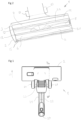
- Fig. 1 - 3 illustrate an embodiment of a vacuum cleaner nozzle according to the present invention.
- the vacuum cleaner nozzle 1 comprises a nozzle housing 2, wheels 21 and a nozzle outlet 20.
- the nozzle outlet 20 is adapted for being connected to the suction hose of a vacuum cleaner (see Fig 4 ) such that when the vacuum cleaner is in an operative mode, vacuum is created under the nozzle as air is sucked through the vacuum cleaner nozzle 1 via the hose to the vacuum cleaner.
- a typical vacuum cleaner is well known by the skilled man and will not be described in further detail here.
- the vacuum cleaner nozzle 1 comprises a base plate 3.
- the base plate 3 is preferably a plastic part, which has been formed by means of, e.g. injection molding in one piece, a metal part, or a combination of plastic and metal.
- the base plate 3 has a suction opening 5.
- the suction opening 5 has, in this exemplifying embodiment, a substantially rectangular shape and has a first longitudinal side 5.1 and a second longitudinal side 5.2.
- the first longitudinal side 5.1 and the second longitudinal side 5.2 are separated a distance which is herein after referred to as the suction opening width w.
- the base plate 3 is arranged such that it is facing the surface being cleaned, typically a floor.
- the longitudinal sides 5.1, 5.2 are perpendicular to the normal cleaning direction (CD), i.e. perpendicular to the movement of the nozzle 1 when it is being operated during vacuuming of a surface.
- CD normal cleaning direction
- an air duct 22 extends through the suction plate 2 to the outlet 20.
- the air duct 22 comprises a flexible tube 23, and a fixed tube 24.
- the fixed tube 24 ends at the outlet 20.
- a vacuum cleaner nozzle (1) configured to be moved over a floor surface (30) is illustrated.
- the nozzle (1) comprises a base plate (3) configured to face the floor surface (30) during operation of the nozzle 1.
- the base plate 3 comprises an elongated suction opening 5.
- the base also comprises a front portion 6 arranged in front of the suction opening 5 and a rear portion 7 arranged behind the suction opening 5.
- the front portion 6 comprises a front surface 12 having a length L1 in a direction substantially parallel to the floor surface 30 during normal use of between 5-10 mm.
- the front surface also comprises an inclined front surface 11 having a length L3 in the same direction, a direction substantially parallel to the floor surface 30 during normal use, of between 20-26 mm.
- the rear portion 7 comprises a rear surface 13 having a length L2 in a direction substantially parallel to the floor surface 30 during normal use of between 5-10 mm, and an inclined rear surface 14 having a length L4 in the same direction of between 18-24 mm.
- the front inclined surface 11 has an inclination angle a1 of between 7-11 degrees in respect of the front surface 12.
- the rear inclined surface 14 has an inclination angle a2 of between 8-12 degrees in respect of the rear surface 13.
- the lengths and inclinations of the front and rear surfaces may be independent from each other's.
- a nozzle comprises a pair of wheels 21 arranged behind the rear portion 7, and preferably behind a nozzle housing 2 is disclosed.
- the invention also covers embodiments without wheels or having different wheel arrangement, eg wheels in the base plate.
- the nozzle comprises a housing 2 arranged above the nozzle base 3.
- the housing 2 comprises a suction channel connecting the suction opening 5 to a nozzle outlet 20.
- the suction opening 5 has a length, in a direction perpendicular to the forward cleaning direction CD during normal use, of between 250-290 mm, preferably between 265-275 mm, and most preferred 270 mm.
- the suction opening has a width of between 15-30 mm, preferably between 20-25 mm, and most preferred 22 mm.
- the anterior part of the front inclined surface 11 comprises a circular arc portion 1) with a radius of between 3-5 mm, and is preferably designed to be arranged at the front of the nozzle base.
- the front surface 12 has a length, in a direction substantially parallel to the floor surface 30 during normal use, of between 6-8 mm, and preferably around 7 mm.
- the rear surface 13 has a length, in a direction substantially parallel to the floor surface 30 during normal use, of between 6-8 mm, and preferably around 7 mm.
- the inclined front surface 11 has a length in a direction perpendicular to the suction opening and parallel to the front surface of between 23-25 mm, and preferably around 24 mm.
- the inclined rear surface 14 has a length in a direction perpendicular to the suction opening and parallel to the rear surface of between 21-23 mm, and preferably around 22 mm.
- the front inclined surface 11 has an inclination angle a1 of between 8-10 degrees, and preferably around 9 degrees.
- the rear inclined surface 14 has an inclination angle a2 of between 9-11 degrees, and preferably around 10 degrees.
- the base plate 3 is made in one piece. It is also possible to make the base plate in two or more pieces.
- the nozzle in the shown embodiments is mainly a floor nozzle intended to clean floors or similar surfaces.
- the nozzle 1 in order to enhance the movement of the carpet fibers during cleaning operation, comprises at least one groove 60, 70 extending parallel to the longitudinal sides 5.1, 5.2 of the suction opening 5.
- the groove 60, 70 is formed in the base plate 3 by a recess in proximity to the suction opening 5.
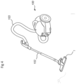
- Figure 4 illustrate a vacuum cleaner 100 comprising a nozzle 1 according to any of the embodiments.
- the nozzle 1 may be connected to a main body 104 of the vacuum cleaner 100 via a tube 102 and a hose 103.
Landscapes
- Engineering & Computer Science (AREA)
- Mechanical Engineering (AREA)
- Nozzles For Electric Vacuum Cleaners (AREA)
Abstract
The invention relates to a vacuum cleaner nozzle (1) configured to be moved over a floor surface (30). The nozzle (1) comprises a base plate (3) configured to face the floor surface (30) during operation of the nozzle (1). The base plate (3) comprises an elongated suction opening (5), a front portion (6) arranged in front of the suction opening (5) and a rear portion (7) arranged behind the suction opening (5). The front portion (6) comprises a front surface (12) having a length (L1) in a direction substantially parallel to the floor surface (30) during normal use of between 5-10 mm, and an inclined front surface (11) having a length (L3) in the same direction of between 20-26 mm. The rear portion (7) comprises a rear surface (13) having a length (L2) in a direction substantially parallel to the floor surface (30) during normal use of between 5-10 mm, and an inclined rear surface (14) having a length (L4) in the same direction of between 18-24 mm. The front inclined surface (11) has an inclination (a1) of between 7-11 degrees in respect of the front surface (12) and the rear inclined surface (14) has an inclination (a2) of between 8-12 degrees in respect of the rear surface (13). The invention also relates to a vacuum cleaner with such a nozzle.
Description
- The present invention relates generally to the field of vacuum cleaners. More specifically, the present invention is related to a nozzle for a vacuum cleaner nozzle and a vacuum cleaner with such a nozzle.
- A vacuum cleaner is a device that uses a suction force generated by a fan unit to create a partial vacuum to suck up objects like dust, particles, fibers, hair etc. usually from floors and carpets. Typically, this is done with a vacuum cleaner nozzle, which is connected via a nozzle outlet to an extension tube and/or a suction hose to a dust compartment within the body of the vacuum cleaner. The suction hose is normally engaged with a removable dust bag arranged inside the vacuum cleaner for collecting dust and foreign materials that are sucked in through the vacuum cleaner nozzle when the vacuum cleaner is in an operative mode. Thus, the dust laden air stream forwards the removed objects, via the nozzle to the hose, and to the body of the vacuum cleaner in which the removed objects are separated from the air stream in the dust bag. Alternatively, dust can be separated from the dust laden air stream using a cyclone or other suitable dust separating unit.
- An essential requirement to be met by a vacuum cleaner nozzle is a high dust pick-up level on carpets. So, in general, the vacuum cleaner nozzle should be formed such, that a maximum dust pick-up level on carpets is reached. On the other hand, a maximization of the dust pick-up level leads to a high motion resistance, i.e. due to the suction force, the vacuum cleaner nozzle can only be moved on the carpet with increased physical strength.
- A further requirement of a vacuum cleaner nozzle is to pick-up larger particles, such as small stones, at the same time as having a high pick-up of fine dust. This is especially a challenge in view of the requirement to have less powerful motors to save energy. With a low power motor it is even more important that the nozzle is optimized for dust pick-up of both fine dust and larger particles as well as having a good user experience by not having a to high motion resistance during use. With a low power motor, and thereby a lower airflow the geometry of the surface in contact with the floor becomes very important. The number of surfaces, length and inclination towards the floor need all to be optimized for the new requirements and usability.
- Drawbacks of known vacuum cleaning nozzles with a high dust pick-up level is the increased motion resistance which leads to a physically demanding cleaning of carpets as well as pushing larger particles in front of the nozzle and not picking them up. Accordingly, there is a need for improvements of existing vacuum cleaner nozzles to solves these drawbacks.
- It is an objective of embodiments of the invention to provide for an improved nozzle for a vacuum cleaner and a vacuum cleaner with an improved dust pick-up level, but with only a limited, if any, increase of motion resistance. The objective is solved by the features of the independent claim. Preferred embodiments are given in the dependent claims. If not explicitly indicated otherwise, embodiments of the invention can be freely combined with each other.
- The invention is intended for battery powered vacuum cleaners as well as mains-operated vacuum cleaners.
- According to a first aspect of the invention, the invention relates to a vacuum cleaner nozzle configured to be moved over a floor surface, wherein the nozzle comprises a base plate configured to face the floor surface during operation of the nozzle. The base plate comprises an elongated suction opening, a front portion arranged in front of the suction opening, a rear portion arranged behind the suction opening. The front portion comprises a front surface having a length in a direction substantially parallel to the floor surface during normal use of between 5-10 mm, and an inclined front surface having a length in the same direction of between 20-26 mm, and the rear portion comprises a rear surface having a length in a direction substantially parallel to the floor surface during normal use, of between 5-10 mm, and an inclined rear surface having a length in the same direction of between 18-24 mm. Furthermore, the front inclined surface has an inclination of between 7-11 degrees in respect of the front surface, and the rear inclined surface has an inclination of between 8-12 degrees in respect of the rear surface.
- Thereby, the optimization of the front portion and rear portion enhances the dust removal and large particle pick-up. Thus, an optimized dust removal is obtained.
- According to preferred embodiments the nozzle comprises a pair of wheels arranged behind the rear portion, and preferably behind a nozzle housing.
- According to preferred embodiments the nozzle comprises a housing arranged above the nozzle base, the housing comprises a suction channel connecting the suction opening to a nozzle outlet.
- According to preferred embodiments the suction opening has a length, in a direction perpendicular to the forward direction during normal use, of between 250-290 mm, preferably between 265-275 mm, and most preferred 270 mm.
- According to preferred embodiments the suction opening has a width of between 15-30 mm, preferably between 20-25 mm, and most preferred 22 mm.
- According to preferred embodiments the anterior part of the front inclined surface comprises a circular arc portion with a radius of between 3-5 mm, and preferably designed to be arranged at the front of the nozzle base.
- Thereby, the circular arc portion front enhances the dust removal in a forward cleaning direction.
- According to preferred embodiments the front surface has a length, in a direction substantially parallel to the floor surface during normal use, of between 6-8 mm, and preferably around 7 mm.
- According to preferred embodiments the rear surface has a length, in a direction substantially parallel to the floor surface during normal use, of between 6-8 mm, and preferably around 7 mm.
- According to preferred embodiments wherein the inclined front surface has a length in a direction perpendicular to the suction opening and parallel to the front surface of between 23-25 mm, and preferably around 24 mm.
- According to preferred embodiments the inclined rear surface has a length in a direction perpendicular to the suction opening and parallel to the rear surface of between 21-23 mm, and preferably around 22 mm.
- According to preferred embodiments the front inclined surface has an inclination of between 8-10 degrees, and preferably around 9 degrees.
- According to preferred embodiments the rear inclined surface has an inclination of between 9-11 degrees, and preferably around 10 degrees.
- According to preferred embodiments the base plate is made in one piece.
- Preferably, Thereby, the dust removal is enhanced, regardless of the direction of movement of said vacuum cleaner nozzle.
- The invention also refers to a vacuum cleaner comprising a nozzle according to anyone of the preceding embodiments.
- The various aspects of the invention, including its particular features and advantages, will be readily understood from the following detailed description and the accompanying drawings, in which:
- Fig. 1
- shows a top view of a vacuum cleaner nozzle according to the invention.
- Fig. 2
- shows a bottom view of the vacuum cleaner nozzle shown in
Fig 1 . - Fig. 3
- shows a sectional view along A-A of the nozzle in in
Fig 1 . - Fig. 4
- shows a vacuum cleaner according to an embodiment.
- The present invention will now be described more fully with reference to the accompanying drawings, in which example embodiments are shown. However, this invention should not be construed as limited to the embodiments set forth herein. Throughout the following description similar reference numerals have been used to denote similar elements, parts, items or features, when applicable.
-
Fig. 1 - 3 illustrate an embodiment of a vacuum cleaner nozzle according to the present invention. The vacuum cleaner nozzle 1 comprises anozzle housing 2,wheels 21 and anozzle outlet 20. Thenozzle outlet 20 is adapted for being connected to the suction hose of a vacuum cleaner (seeFig 4 ) such that when the vacuum cleaner is in an operative mode, vacuum is created under the nozzle as air is sucked through the vacuum cleaner nozzle 1 via the hose to the vacuum cleaner. The operation of a typical vacuum cleaner is well known by the skilled man and will not be described in further detail here. - The vacuum cleaner nozzle 1 comprises a
base plate 3. Thebase plate 3 is preferably a plastic part, which has been formed by means of, e.g. injection molding in one piece, a metal part, or a combination of plastic and metal. Thebase plate 3 has a suction opening 5. Thesuction opening 5 has, in this exemplifying embodiment, a substantially rectangular shape and has a first longitudinal side 5.1 and a second longitudinal side 5.2. The first longitudinal side 5.1 and the second longitudinal side 5.2 are separated a distance which is herein after referred to as the suction opening width w. - During normal operation of the nozzle 1, the
base plate 3 is arranged such that it is facing the surface being cleaned, typically a floor. - In normal operation of the nozzle 1, the longitudinal sides 5.1, 5.2 are perpendicular to the normal cleaning direction (CD), i.e. perpendicular to the movement of the nozzle 1 when it is being operated during vacuuming of a surface. Starting from the
suction opening 5, anair duct 22 extends through thesuction plate 2 to theoutlet 20. Theair duct 22 comprises a flexible tube 23, and a fixedtube 24. The fixedtube 24 ends at theoutlet 20. - In
Fig 1-3 a vacuum cleaner nozzle (1) configured to be moved over a floor surface (30) is illustrated. The nozzle (1) comprises a base plate (3) configured to face the floor surface (30) during operation of the nozzle 1. Thebase plate 3 comprises anelongated suction opening 5. The base also comprises a front portion 6 arranged in front of thesuction opening 5 and arear portion 7 arranged behind thesuction opening 5. The front portion 6 comprises afront surface 12 having a length L1 in a direction substantially parallel to thefloor surface 30 during normal use of between 5-10 mm. - The front surface also comprises an inclined
front surface 11 having a length L3 in the same direction, a direction substantially parallel to thefloor surface 30 during normal use, of between 20-26 mm. - The
rear portion 7 comprises a rear surface 13 having a length L2 in a direction substantially parallel to thefloor surface 30 during normal use of between 5-10 mm, and an inclinedrear surface 14 having a length L4 in the same direction of between 18-24 mm. - In the disclosed embodiments the front
inclined surface 11 has an inclination angle a1 of between 7-11 degrees in respect of thefront surface 12. The rearinclined surface 14 has an inclination angle a2 of between 8-12 degrees in respect of the rear surface 13. The lengths and inclinations of the front and rear surfaces may be independent from each other's. - In
fig 1-3 a nozzle comprises a pair ofwheels 21 arranged behind therear portion 7, and preferably behind anozzle housing 2 is disclosed. The invention also covers embodiments without wheels or having different wheel arrangement, eg wheels in the base plate. - The nozzle comprises a
housing 2 arranged above thenozzle base 3. Thehousing 2 comprises a suction channel connecting thesuction opening 5 to anozzle outlet 20. - The
suction opening 5 has a length, in a direction perpendicular to the forward cleaning direction CD during normal use, of between 250-290 mm, preferably between 265-275 mm, and most preferred 270 mm. - The suction opening has a width of between 15-30 mm, preferably between 20-25 mm, and most preferred 22 mm.
- The anterior part of the front
inclined surface 11 comprises a circular arc portion 1) with a radius of between 3-5 mm, and is preferably designed to be arranged at the front of the nozzle base. - The
front surface 12 has a length, in a direction substantially parallel to thefloor surface 30 during normal use, of between 6-8 mm, and preferably around 7 mm. - The rear surface 13 has a length, in a direction substantially parallel to the
floor surface 30 during normal use, of between 6-8 mm, and preferably around 7 mm. - The inclined
front surface 11 has a length in a direction perpendicular to the suction opening and parallel to the front surface of between 23-25 mm, and preferably around 24 mm. - The inclined
rear surface 14 has a length in a direction perpendicular to the suction opening and parallel to the rear surface of between 21-23 mm, and preferably around 22 mm. - The front
inclined surface 11 has an inclination angle a1 of between 8-10 degrees, and preferably around 9 degrees. - The rear
inclined surface 14 has an inclination angle a2 of between 9-11 degrees, and preferably around 10 degrees. - In
Fig 1-3 thebase plate 3 is made in one piece. It is also possible to make the base plate in two or more pieces. - The nozzle in the shown embodiments is mainly a floor nozzle intended to clean floors or similar surfaces.
- In embodiments, in order to enhance the movement of the carpet fibers during cleaning operation, the nozzle 1 comprises at least one groove 60, 70 extending parallel to the longitudinal sides 5.1, 5.2 of the
suction opening 5. Preferably, the groove 60, 70 is formed in thebase plate 3 by a recess in proximity to thesuction opening 5. -
Figure 4 illustrate avacuum cleaner 100 comprising a nozzle 1 according to any of the embodiments. The nozzle 1 may be connected to a main body 104 of thevacuum cleaner 100 via atube 102 and ahose 103. - Above, embodiments of the vacuum cleaner nozzle according to the present invention as defined in the appended claims have been described. These should be seen as merely nonlimiting examples.
- It will be appreciated that those skilled in the art can make various significant modifications and/or improvements to the embodiments of the invention described in this specification without departing from the scope of the invention as defined by the appended claims.
-
- 1 : nozzle
- 2 : Nozzle housing
- 3 : Base plate
- 5: Suction opening
- 5.1: first longitudinal edge
- 5.2: second longitudinal edge
- 6: Front portion
- 7: Rear portion
- 11 front inclined surface
- 12 Front surface
- 13 Rear surface
- 14 Rear inclined surface
- 15: Arc portion
- 20: Air outlet
- 21: Wheel/s
- 22: Air duct
- 23: Flexible tube
- 24: Fixed tube
- 30: Floor surface
- 60: groove
- 70 : groove
- 100: Vacuum cleaner
- 102: Tube
- 103: Hose
- CD : cleaning direction
- w : width of suction opening
- a1: angle of front inclined surface to front surface
- a2: angle of rear inclined surface to rear surface
Claims (15)
- A vacuum cleaner nozzle (1) configured to be moved over a floor surface (30),
wherein the nozzle (1) comprises a base plate (3) configured to face the floor surface (30) during operation of the nozzle (1),- wherein the base plate (3) comprises an elongated suction opening (5),- a front portion (6) arranged in front of the suction opening (5),- a rear portion (7) arranged behind the suction opening (5),- wherein the front portion (6) comprises a front surface (12) having a length (L1) in a direction substantially parallel to the floor surface (30) during normal use of between 5-10 mm, and an inclined front surface (11) having a length (L3) in the same direction of between 20-26 mm, and- wherein the rear portion (7) comprises a rear surface (13) having a length (L2) in a direction substantially parallel to the floor surface (30) during normal use of between 5-10 mm, and an inclined rear surface (14) having a length (L4) in the same direction of between 18-24 mm, and- the front inclined surface (11) has an inclination angle (a1) of between 7-11 degrees in respect of the front surface (12),- the rear inclined surface (14) has an inclination angle (a2) of between 8-12 degrees in respect of the rear surface (13). - A vacuum cleaner nozzle according to claim 1, wherein, the nozzle comprises a pair of wheels (21) arranged behind the rear portion (7), and preferably behind a nozzle housing (2).
- A vacuum cleaner nozzle according to any of the claims 1-2, wherein the nozzle comprises a housing (2) arranged above the nozzle base (3), the housing (2) comprises a suction channel connecting the suction opening (5) to a nozzle outlet (20).
- A vacuum cleaner nozzle according to any of the claims 1-3, wherein the suction opening (5) has a length, in a direction perpendicular to the forward cleaning direction (CD) during normal use, of between 250-290 mm, preferably between 265-275 mm, and most preferred 270 mm.
- A vacuum cleaner nozzle according to any of the claims 1-4, wherein the suction opening has a width of between 15-30 mm, preferably between 20-25 mm, and most preferred 22 mm.
- A vacuum cleaner nozzle according to any of the claims 1-5, wherein the anterior part of the front inclined surface (11) comprises a circular arc portion (15) with a radius of between 3-5 mm, and is preferably designed to be arranged at the front of the nozzle base.
- A vacuum cleaner nozzle according to any of the claims 1-6, wherein the front surface (12) has a length, in a direction substantially parallel to the floor surface (30) during normal use, of between 6-8 mm, and preferably around 7 mm.
- A vacuum cleaner nozzle according to any of the claims 1-7, wherein the rear surface (13) has a length, in a direction substantially parallel to the floor surface (30) during normal use, of between 6-8 mm, and preferably around 7 mm.
- A vacuum cleaner nozzle according to any of the claims 1-8, wherein the inclined front surface (11) has a length in a direction perpendicular to the suction opening and parallel to the floor surface (30) of between 23-25 mm, and preferably around 24 mm.
- A vacuum cleaner nozzle according to any of the claims 1-9, wherein the inclined rear surface (14) has a length in a direction perpendicular to the suction opening and parallel to the floor surface (30) of between 21-23 mm, and preferably around 22 mm.
- A vacuum cleaner nozzle according to any of the claims 1-10, wherein the front inclined surface (11) has an inclination angle (a1) of between 8-10 degrees, and preferably around 9 degrees.
- A vacuum cleaner nozzle according to any of the claims 1-11, wherein the rear inclined surface (14) has an inclination angle (a2) of between 9-11 degrees, and preferably around 10 degrees.
- A vacuum cleaner nozzle according to any of the claims 1-12, wherein the base plate (3) is made in one piece.
- A vacuum cleaner nozzle according to any of the claims 1-13, wherein the nozzle is a floor nozzle.
- A vacuum cleaner (100) comprising a vacuum cleaner nozzle (1, 1') according to any one of the preceding claims.
Applications Claiming Priority (1)
| Application Number | Priority Date | Filing Date | Title |
|---|---|---|---|
| SE2330398A SE547527C2 (en) | 2023-09-12 | 2023-09-12 | Nozzle for a vacuum cleaner and a vacuum cleaner having such a nozzle |
Publications (1)
| Publication Number | Publication Date |
|---|---|
| EP4523588A1 true EP4523588A1 (en) | 2025-03-19 |
Family
ID=92503848
Family Applications (1)
| Application Number | Title | Priority Date | Filing Date |
|---|---|---|---|
| EP24195521.0A Pending EP4523588A1 (en) | 2023-09-12 | 2024-08-21 | Nozzle for a vacuum cleaner and a vacuum cleaner having such a nozzle |
Country Status (3)
| Country | Link |
|---|---|
| EP (1) | EP4523588A1 (en) |
| CN (1) | CN119606251A (en) |
| SE (1) | SE547527C2 (en) |
Citations (3)
| Publication number | Priority date | Publication date | Assignee | Title |
|---|---|---|---|---|
| EP3087891A1 (en) * | 2015-04-29 | 2016-11-02 | Seb S.A. | Vacuum cleaner nozzle flange |
| EP3494852A1 (en) * | 2017-12-11 | 2019-06-12 | New Ermes Europe S.r.l. | Base plate for a vacuum cleaner suction head for the suction of fine dust and large debris |
| EP3639715A1 (en) * | 2018-10-15 | 2020-04-22 | Wessel-Werk GmbH | Floor nozzle for a vacuum cleaner |
Family Cites Families (8)
| Publication number | Priority date | Publication date | Assignee | Title |
|---|---|---|---|---|
| DE102007009958B4 (en) * | 2007-03-01 | 2013-08-01 | Wessel-Werk Gmbh | Sheet-metal sole and method for its design |
| DK2944242T3 (en) * | 2014-05-14 | 2019-11-11 | New Ermes Europe Srl | Suction head for a vacuum cleaner or similar with improved base plate channel |
| FR3035583B1 (en) * | 2015-04-29 | 2017-12-01 | Seb Sa | VACUUM SUCKER SOLE |
| ITUB20160903A1 (en) * | 2016-02-19 | 2017-08-19 | New Ermes Europe Srl | Base plate for suction head for vacuum cleaner or similar |
| EP3366179B1 (en) * | 2017-02-23 | 2019-07-24 | Wessel-Werk GmbH | Static floor nozzle for a vacuum cleaner |
| DE102018123465A1 (en) * | 2018-09-24 | 2020-03-26 | Wessel-Werk Gmbh | Vacuum cleaner floor nozzle arrangement |
| FR3094623B1 (en) * | 2019-04-05 | 2022-12-16 | Seb Sa | Vacuum nozzle with rear scraping rib |
| DE102019117777A1 (en) * | 2019-07-02 | 2021-01-07 | Miele & Cie. Kg | Sliding sole, vacuum cleaner nozzle and vacuum cleaner |
-
2023
- 2023-09-12 SE SE2330398A patent/SE547527C2/en unknown
-
2024
- 2024-08-21 EP EP24195521.0A patent/EP4523588A1/en active Pending
- 2024-08-30 CN CN202411211815.4A patent/CN119606251A/en active Pending
Patent Citations (3)
| Publication number | Priority date | Publication date | Assignee | Title |
|---|---|---|---|---|
| EP3087891A1 (en) * | 2015-04-29 | 2016-11-02 | Seb S.A. | Vacuum cleaner nozzle flange |
| EP3494852A1 (en) * | 2017-12-11 | 2019-06-12 | New Ermes Europe S.r.l. | Base plate for a vacuum cleaner suction head for the suction of fine dust and large debris |
| EP3639715A1 (en) * | 2018-10-15 | 2020-04-22 | Wessel-Werk GmbH | Floor nozzle for a vacuum cleaner |
Also Published As
| Publication number | Publication date |
|---|---|
| SE547527C2 (en) | 2025-09-14 |
| SE2330398A1 (en) | 2025-03-13 |
| CN119606251A (en) | 2025-03-14 |
Similar Documents
| Publication | Publication Date | Title |
|---|---|---|
| US8214967B2 (en) | Floor tool | |
| US7124467B2 (en) | Edge cleaning system for vacuum cleaner | |
| CN108289581B (en) | Suction head for vacuum cleaner and operation method thereof | |
| US20160095485A1 (en) | Vacuum cleaner including a removable dirt collection assembly | |
| EP2276384A1 (en) | Vacuum cleaner nozzle | |
| KR20180010725A (en) | Cleaner | |
| WO2021069863A1 (en) | Cleaner head for a vacuum cleaning appliance | |
| GB2441495A (en) | Suction diversion channel in vacuum cleaner head | |
| EP3010385B1 (en) | Nozzle for a vacuum cleaner and vacuum cleaner | |
| CN119606251A (en) | Suction nozzle for vacuum cleaner and vacuum cleaner having such suction nozzle | |
| JP5978913B2 (en) | Electric vacuum cleaner | |
| JP7832481B2 (en) | Nozzles and work machines | |
| JP7791976B1 (en) | Electric cleaning system | |
| JP5681776B1 (en) | Suction head and vacuum cleaner | |
| JP6306303B2 (en) | Electric vacuum cleaner | |
| JP2020039407A (en) | Suction tool and vacuum cleaner | |
| KR100783144B1 (en) | Dust bucket of vacuum cleaner | |
| JP2010252981A (en) | Suction port and vacuum cleaner | |
| JP2017018413A (en) | Electric vacuum cleaner | |
| WO2014122219A1 (en) | Vacuum cleaner nozzle with support means | |
| JP2013059414A (en) | Suction port body and vacuum cleaner | |
| JP6133179B2 (en) | Electric vacuum cleaner | |
| JP2017023349A (en) | Suction port body and vacuum cleaner | |
| JPH1043098A (en) | Vacuum cleaner floor inlet | |
| JP2002330908A (en) | Vacuum cleaner suction tool and vacuum cleaner using the same |
Legal Events
| Date | Code | Title | Description |
|---|---|---|---|
| PUAI | Public reference made under article 153(3) epc to a published international application that has entered the european phase |
Free format text: ORIGINAL CODE: 0009012 |
|
| STAA | Information on the status of an ep patent application or granted ep patent |
Free format text: STATUS: THE APPLICATION HAS BEEN PUBLISHED |
|
| AK | Designated contracting states |
Kind code of ref document: A1 Designated state(s): AL AT BE BG CH CY CZ DE DK EE ES FI FR GB GR HR HU IE IS IT LI LT LU LV MC ME MK MT NL NO PL PT RO RS SE SI SK SM TR |
|
| STAA | Information on the status of an ep patent application or granted ep patent |
Free format text: STATUS: REQUEST FOR EXAMINATION WAS MADE |
|
| 17P | Request for examination filed |
Effective date: 20250919 |