EP4523567A1 - Slide rail assembly - Google Patents
Slide rail assembly Download PDFInfo
- Publication number
- EP4523567A1 EP4523567A1 EP24175888.7A EP24175888A EP4523567A1 EP 4523567 A1 EP4523567 A1 EP 4523567A1 EP 24175888 A EP24175888 A EP 24175888A EP 4523567 A1 EP4523567 A1 EP 4523567A1
- Authority
- EP
- European Patent Office
- Prior art keywords
- rail
- feature
- compensating device
- state
- slide rail
- Prior art date
- Legal status (The legal status is an assumption and is not a legal conclusion. Google has not performed a legal analysis and makes no representation as to the accuracy of the status listed.)
- Pending
Links
Images




Classifications
-
- A—HUMAN NECESSITIES
- A47—FURNITURE; DOMESTIC ARTICLES OR APPLIANCES; COFFEE MILLS; SPICE MILLS; SUCTION CLEANERS IN GENERAL
- A47B—TABLES; DESKS; OFFICE FURNITURE; CABINETS; DRAWERS; GENERAL DETAILS OF FURNITURE
- A47B88/00—Drawers for tables, cabinets or like furniture; Guides for drawers
- A47B88/40—Sliding drawers; Slides or guides therefor
- A47B88/49—Sliding drawers; Slides or guides therefor with double extensible guides or parts
- A47B88/493—Sliding drawers; Slides or guides therefor with double extensible guides or parts with rollers, ball bearings, wheels, or the like
-
- A—HUMAN NECESSITIES
- A47—FURNITURE; DOMESTIC ARTICLES OR APPLIANCES; COFFEE MILLS; SPICE MILLS; SUCTION CLEANERS IN GENERAL
- A47B—TABLES; DESKS; OFFICE FURNITURE; CABINETS; DRAWERS; GENERAL DETAILS OF FURNITURE
- A47B88/00—Drawers for tables, cabinets or like furniture; Guides for drawers
- A47B88/40—Sliding drawers; Slides or guides therefor
- A47B88/44—Sequencing or synchronisation of drawer slides or functional units
- A47B88/443—Successive movement of rails within drawer slides, i.e. at least one rail element is not moving during the movement of other elements
-
- A—HUMAN NECESSITIES
- A47—FURNITURE; DOMESTIC ARTICLES OR APPLIANCES; COFFEE MILLS; SPICE MILLS; SUCTION CLEANERS IN GENERAL
- A47B—TABLES; DESKS; OFFICE FURNITURE; CABINETS; DRAWERS; GENERAL DETAILS OF FURNITURE
- A47B88/00—Drawers for tables, cabinets or like furniture; Guides for drawers
- A47B88/40—Sliding drawers; Slides or guides therefor
- A47B88/44—Sequencing or synchronisation of drawer slides or functional units
- A47B88/447—Simultaneous movement of rails within drawer slides, i.e. with a coordination of movement with all rail elements moving at the same time
-
- A—HUMAN NECESSITIES
- A47—FURNITURE; DOMESTIC ARTICLES OR APPLIANCES; COFFEE MILLS; SPICE MILLS; SUCTION CLEANERS IN GENERAL
- A47B—TABLES; DESKS; OFFICE FURNITURE; CABINETS; DRAWERS; GENERAL DETAILS OF FURNITURE
- A47B88/00—Drawers for tables, cabinets or like furniture; Guides for drawers
- A47B88/40—Sliding drawers; Slides or guides therefor
- A47B88/49—Sliding drawers; Slides or guides therefor with double extensible guides or parts
-
- A—HUMAN NECESSITIES
- A47—FURNITURE; DOMESTIC ARTICLES OR APPLIANCES; COFFEE MILLS; SPICE MILLS; SUCTION CLEANERS IN GENERAL
- A47B—TABLES; DESKS; OFFICE FURNITURE; CABINETS; DRAWERS; GENERAL DETAILS OF FURNITURE
- A47B2210/00—General construction of drawers, guides and guide devices
- A47B2210/0002—Guide construction for drawers
- A47B2210/0029—Guide bearing means
- A47B2210/0037—Rollers
- A47B2210/004—Rollers cages therefor, e.g. for telescopic slides
Definitions
- the present invention relates a slide rail assembly according to the pre-characterizing clause of claim 1.
- U.S. Patent No. 11,272,784 B2 it discloses a drawer pull-out guide including at least two guide rails displaceable relative to each other and a sliding carriage having load-transmitting rolling members.
- the sliding carriage is movably supported between the at least two guide rails.
- a relative position of the at least two guide rails is preset to a predetermined relative position upon a movement of the sliding carriage.
- the drawer pull-out guide further includes a compensating device for compensating an error of the relative position of the at least two guide rails, i.e., a deviation from the predetermined relative position.
- the compensating device has an actuating device and a switching device.
- the actuating device is configured to be actuated by one of the at least two guide rails for compensating the error of the relative position of the at least two guide rails.
- the switching device is configured to disengage the compensating device from the one of the at least two guide rails when the at least two guide rails is in the predetermined relative position.
- the present invention aims at providing a slide rail assembly for compensating an error of a relative position of at least two slide rails by utilizing a compensating device.
- the claimed slide rail assembly includes a first rail, a second rail, a first feature, a compensating device and a third rail.
- the first rail is displaceable along a first direction or a second direction opposite to the first direction.
- the first feature is arranged on the first rail.
- the compensating device is mounted on the second rail and movable between a first state and a second state.
- the compensating device includes a second feature.
- the second rail is movably mounted on the third rail.
- the third rail includes a supporting section and a blocking portion, and the supporting section is configured to support the second rail or the compensating device.
- the first rail displacing along a first direction drives the blocking portion of the third rail and the compensating device in the first state to block each other to stop the second rail until the first rail is displaced along the first direction over a predetermined distance to drive the first feature and the compensating device in the first state to abut against each other to drive the compensating device to move from the first state to the second state.
- the blocking portion of the third rail does not block the compensating device.
- a slide rail assembly 20 includes a first rail 22, a second rail 24, a third rail 26 and a first aid-sliding device 28.
- the slide rail assembly 20 further includes a second aid-sliding device 30.
- the second rail 24 is movably mounted between the third rail 26 and the first rail 22, and the first rail 22 and the second rail 24 are displaceable relative to each other, and/or relative to the third rail 26 along a longitudinal direction.
- the longitudinal direction can be defined by a length direction of a slide rail, e.g., the first rail 22, the second rail 24 or the third rail 26, and parallel to an X axis.
- a transverse direction can be defined by a lateral direction or a width direction of the slide rail and parallel to a Y axis.
- a vertical direction can be defined by a height direction of the slide rail and parallel to a Z axis.
- the second rail 24 is configured to be movably mounted on the third rail 26, and the first rail 22 is configured to be movably mounted on the second rail 24.
- the first aid-sliding device 28 is movably mounted between the first rail 22 and the second rail 24 for facilitating a relative displacement of the first rail 22 and the second rail 24.
- the first aid-sliding device 28 includes at least one first rotating member 32 configured to be rotatably supported between the first rail 22 and the second rail 24, and the first rotating member 32 can be a roller or a ball.
- the second aid-sliding device 30 is movably mounted between the second rail 24 and the third rail 26 for facilitating a relative displacement of the second rail 24 and the third rail 26.
- the second aid-sliding device 30 includes at least one second rotating member 34 configured to be rotatably supported between the second rail 24 and the third rail 26, and the second rotating member 34 can be a roller or a ball.
- the slide rail assembly 20 further includes a first feature 36 and a compensating device 38.
- the first feature 36 and the compensating device 38 are arranged on one and the other one of the first rail 22 and the second rail 24, respectively.
- the first feature 36 is arranged on the first rail 22, and the compensating device 38 is movably mounted on the second rail 24.
- the first feature 36 can be arranged on the first rail 22 directly or indirectly, and the compensating device 38 can be pivotally connected to the second rail 24 by a shaft member 40.
- the first rail 22 has a first end portion 22a and a second end portion 22b located opposite to the first end portion 22a
- the second rail 24 has a first end portion 24a and a second end portion 24b located opposite to the first end portion 24a.
- first end portion 22a and the second end portion 22b of the first rail 22 are a front end portion and a rear end portion of the first rail 22, respectively, and the first end portion 24a and the second end portion 24b of the second rail 24 are a front end portion and a rear end portion of the second rail 24, respectively.
- first feature 36 is a protruding structure located adjacent to the first end portion 22a of the first rail 22, and the compensating device 38 is located arranged adjacent to the first end portion 24a of the second rail 24.
- the present invention is not limited to this embodiment.
- the third rail 26 has a first end portion 26a and a second end portion 26b located opposite to the first end portion 26a.
- the first end portion 26a and the second end portion 26b of the third rail 26 are a front end portion and a rear end portion of the third rail 26, respectively.
- the third rail 26 includes a supporting section 42 and a blocking portion 44.
- the supporting section 42 extends between the first end portion 26a and the second end portion 26b of the third rail 26 along the longitudinal direction and configured to support the second rail 24 and/or the compensating device 38.
- the blocking portion 44 is a protrusion arranged on a lateral side 46 of the supporting section 42 and located adjacent to the first end portion 26a of the third rail 26.
- the present invention is not limited to this embodiment.
- the compensating device 38 includes a main body 48, a working member 50, a predetermined feature 52, a resilient member 54 and a resilient portion 56.
- the compensating device 38 further includes a recovering resilient member 58.
- the main body 48 includes a first main body portion 60 and a second main body portion 62 connected to the first main body portion 60.
- the second main body portion 62 is connected to the first main body portion 60 in a substantially perpendicular manner.
- the shaft member 40 passes through the second main body portion 62 along the lateral direction or the transverse direction for achieving a pivotal connection of the compensating device 38 and the second rail 24.
- the working member 50 is movably mounted on the main body 48.
- a second feature 64 is arranged on the working member 50 and configured to cooperate with the first feature 36.
- the working member 50 is pivotally connected to a predetermined part 68 of the first main body portion 60 by a connecting member 66.
- the working member 50 has a first end and a second end located opposite to the first end.
- the first end and the second end of the working member 50 are a front end and a rear end of the working member 50, respectively.
- the first main body portion 60 includes a blocking wall 70 located adjacent to the first end of the working member 50 for stopping the working member 50 at a working position K, and an avoiding space adjacent to the second end of the working member 50 for allowing the working member 50 to move away from the working position K.
- the predetermined feature 52 is arranged on the main body 48.
- the predetermined feature 52 can be arranged on the second main body portion 62 of the main body 48 directly or indirectly.
- the predetermined feature 52 can be a protrusion.
- the present invention is not limited to this embodiment.
- the main body 48 has a first end 48a and a second end 48b located opposite to the first end 48a.
- the first end 48a and the second end 48b of the main body 48 are a front end and a rear end of the main body 48, respectively.
- the predetermined feature 52 is spaced away from the first end 48a of the main body 48 by a distance G.
- the resilient member 54 is configured to provide a resilient force to the compensating device 38.
- a portion of the resilient member 54 is mounted inside a receiving space 72 of the first main body portion 60, and another portion of the resilient member 54 stretches out of the receiving space 72.
- the resilient portion 56 is arranged on the main body 48.
- the resilient portion 56 is an extending arm.
- the present invention is not limited to this embodiment.
- the recovering resilient member 58 is configured to provide a recovering resilient force to the working member 50, so as to drive the working member 50 to move toward the working position K.
- the compensating device 38 is in a first state S1 in response to the resilient force provided by the resilient member 54, and the working member 50 is retained at the working position K in response to the recovering resilient force provided by the recovering resilient member 58.
- the second feature 64 is spaced away from the first feature 36 by a first longitudinal distance L1
- the predetermined feature 52 is located at a position corresponding to the blocking portion 44 of the third rail 26, e.g., the predetermined feature 52 and the blocking portion 44 of the third rail 26 are aligned with each other along the longitudinal direction.
- the resilient member 54 is abutted between the main body 48 and the second rail 24, and the resilient portion 56 is located adjacent to the second rail 24.
- the present invention is not limited to this embodiment.
- the first rail 22 is located at a retracted position R relative to the third rail 26.
- the second rail 24 is configured to be displaced to a predetermined position P0 in response to a movement of the first rail 22 to the retracted position R.
- the second rail 24 might be located a position deviated from the predetermined position P0 due to repeated opening movements and retracting movements of the first rail 22 and the second rail 24 relative to the third rail 26, an operational mistake, and/or an unexpected external force.
- the second feature 64 is spaced away from the first feature 36 by a second longitudinal distance L2 less than the first longitudinal distance L1.
- the first rail 22 displacing along a first direction, e.g., an opening direction D1
- a first direction e.g., an opening direction D1
- the second rail 24 drives the first feature 36 and the second feature 64 of the compensating device 38 in the first state S1 to abut against each other to drive the second rail 24 to synchronously displace together with the first rail 22 along the opening direction D1 for a first predetermined distance, e.g., from a first position M1 to a second position M2, so as to compensate a lagging position error, i.e., a deviation between the lagging position P1 and the predetermined position P0, until the compensating device 38 is driven to pivot relative to the third rail 26 from the first state S 1 to a second state S2 along a first pivoting direction R1 by the shaft member 40.
- a first predetermined distance e.g., from a first position M1 to a second position M2
- the predetermined feature 52 of the compensating device 38 is moved away from the position corresponding to the blocking portion 44 of the third rail 26, e.g., the predetermined feature 52 of the compensating device 38 is misaligned with the blocking portion 44 of the third rail 26 along the longitudinal direction.
- a blocking relation of the blocking portion 44 of the third rail 26 and the predetermined feature 52 of the compensating device 38 is prevented for allowing a further displacement of the second rail 24 along the opening direction D1 without any obstruction because the predetermined feature 52 of the compensating device 38 is misaligned with the blocking portion 44 of the third rail 26 along the longitudinal direction.
- one of the first feature 36 and the second feature 64 includes a first guiding portion 74.
- the first guiding portion 74 can be an inclined surface or an arc surface.
- the first feature 36 includes the first guiding portion 74.
- the present invention is not limited to this embodiment.
- the compensating device 38 After the compensating device 38 exceeds the first end portion 26a of the third rail 26, the compensating device 38 is free to be driven to move from the first state S 1 as shown in FIG. 9 to the second state S2 as shown in FIG. 10 along the first pivoting direction R1 by an abutment of the first guiding portion 74 and the second feature 64.
- a guiding section 76 is formed on a connection of the supporting section 42 and the first end portion 26a of the third rail 26 for facilitating the compensating device 38 to move from the first state S1 to the second state S2 relative to the third rail 26.
- the guiding section 76 can be a chamfer edge.
- the first rail 22 and the second rail 24 can be displaced relative to the third rail 26 along the opening direction D1 individually, so as to switch the slide rail assembly 20 to an extended state as shown in FIG. 11 by locating the first rail 22 at an extended position E, e.g., a fully extended position.
- the compensating device 38 moves from the second state S2 as shown in FIG. 10 to the first state S1 as shown in FIG. 11 along a second pivoting direction R2 opposite to the first pivoting direction R1 in response to the resilient force provided by the resilient member 54.
- the resilient portion 56 is configured to abut against the second rail 24 for providing a noise-reducing effect and/or an impact-buffering effect.
- the second feature 64 is spaced away from the first feature 36 by a third longitudinal distance L3 greater than the first longitudinal distance L1.
- the first rail 22 displacing along the opening direction D1 from the retracted position R drives the blocking portion 44 of the third rail 26 and the predetermined feature 52 of the compensating device 38 in the first state S1 to block each other to stop the second rail 24, so as to compensate an advancing position error, i.e., a deviation between the advancing position P2 and the predetermined position P0, until the first rail 22 is displaced along the opening direction D1 over a second predetermined distance, e.g., a distance N from a position as shown in FIG. 13 to a position as shown in FIG.
- a second predetermined distance e.g., a distance N from a position as shown in FIG. 13 to a position as shown in FIG.
- the first feature 36 is not blocked by the second feature 64 of the compensating device 38 for allowing a further displacement of the first rail 22 along the opening direction D1.
- the first feature 36 is not blocked by the second feature 64 of the compensating device 38 for allowing a further displacement of the first rail 22 along the opening direction D1.
- the predetermined feature 52 of the compensating device 38 is moved away from the position corresponding to the blocking portion 44 of the third rail 26, e.g., the predetermined feature 52 of the compensating device 38 is misaligned with the blocking portion 44 of the third rail 26 along the longitudinal direction, such that the blocking relation of the blocking portion 44 of the third rail 26 and the predetermined feature 52 of the compensating device 38 is terminated, for allowing a further displacement of the second rail 24 along the opening direction D 1.
- the resilient member 54 is resiliently deformed, and the resilient portion 56 is moved away from the second rail 24.
- the compensating device 38 exceeds the first end portion 26a of the third rail 26, such that the compensating device 38 can be driven to move from the first state S1 as shown in FIG. 14 to the second state S2 as shown in FIG. 15 along the first pivoting direction R1 by an abutment of the first guiding portion 74 and the second feature 64.
- the first rail 22 and the second rail 24 can be displaced relative to the third rail 26 along the opening direction D1 individually to switch the slide rail assembly 20 in the extended state as shown in FIG. 11 by locating the first rail 22 at the extended position E.
- the compensating device 38 moves from the second state S2 as shown in FIG. 15 to the first state S1 as shown in FIG. 11 along the second pivoting direction R2 in response to the resilient force provided by the resilient member 54.
- the resilient portion 56 is configured to abut against the second rail 24 for providing a noise-reducing effect and/or an impact-buffering effect.
- the second rail 24 can be driven to displace back to the predetermined position P0 as shown in FIG. 6 rather than the advancing position P2 in response to the displacement of the first rail 22 from the extended position E to the retracted position R along the retracting direction D2.
- one of the first feature 36 and the second feature 64 includes a second guiding portion 78.
- the second guiding portion 78 can be an inclined surface or an arc surface.
- the first feature 36 includes the second guiding portion 78, and the second guiding portion 78 is located opposite to the first guiding portion 74.
- the first guiding portion 74 and the second guiding portion 78 are located adjacent to a front side and a rear side of the first feature 36.
- the present invention is not limited to this embodiment.
- the second guiding portion 78 is configured to abut against the working member 50 to drive the working member 50 to pivot away from the working position K along a predetermined pivoting direction r, so as to allow the first feature 36 to pass over the working member 50 along the retracting direction D2.
- the working member 50 can pivot back to the working position K in response to the recovering resilient force provided by the recovering resilient member 58.
- the slide rail assembly 20 can be adapted for a furniture.
- the third rail 26 of each of the two slide rail assemblies 20 is configured to be mounted on the cabinet body 80
- the first rail 22 of each of the two slide rail assemblies 20 is configured to be support the drawer 82.
- the slide rail assembly 20 includes the following characteristics.
Landscapes
- Drawers Of Furniture (AREA)
- Forklifts And Lifting Vehicles (AREA)
- Lift-Guide Devices, And Elevator Ropes And Cables (AREA)
- Bearings For Parts Moving Linearly (AREA)
Abstract
A slide rail assembly (20) includes a first rail (22), a second rail (24), an aid-sliding device, a compensating device (38) and a third rail (26). The aid-sliding device is movably mounted between the first rail (22) and the second rail (24). The compensating device (38) is movably mounted on the second rail (24). The second rail (24) is configured to be movably mounted on the third rail (26). The compensating device (38) is configured to compensating an error of a relative position of the first rail (22) and the second rail (24).
Description
- The present invention relates a slide rail assembly according to the pre-characterizing clause of
claim 1. - In
U.S. Patent No. 11,272,784 B2 - However, in order to meet various requirements, it becomes an important topic to provide an alternative solution for compensating an error of a relative position of at least two slide rails.
- This is mind, the present invention aims at providing a slide rail assembly for compensating an error of a relative position of at least two slide rails by utilizing a compensating device.
- This is achieved by a slide rail assembly according to
claim 1. The dependent claims pertain to corresponding further developments and improvements. - As will be seen more clearly from the detailed description following below, the claimed slide rail assembly includes a first rail, a second rail, a first feature, a compensating device and a third rail. The first rail is displaceable along a first direction or a second direction opposite to the first direction. The first feature is arranged on the first rail. The compensating device is mounted on the second rail and movable between a first state and a second state. The compensating device includes a second feature. The second rail is movably mounted on the third rail. The third rail includes a supporting section and a blocking portion, and the supporting section is configured to support the second rail or the compensating device. After the second rail is displaced to an advancing position relative to the first rail, the first rail displacing along a first direction drives the blocking portion of the third rail and the compensating device in the first state to block each other to stop the second rail until the first rail is displaced along the first direction over a predetermined distance to drive the first feature and the compensating device in the first state to abut against each other to drive the compensating device to move from the first state to the second state. When the compensating device is in the second state, the blocking portion of the third rail does not block the compensating device.
- In the following, the invention is further illustrated by way of example, taking reference to the accompanying drawings. Thereof:
-
FIG. 1 is a schematic diagram of a slide rail assembly according to an embodiment of the present invention, -
FIG. 2 is an exploded diagram of the slide rail assembly according to the embodiment of the present invention, -
FIG. 3 is a partial diagram of the slide rail assembly according to the embodiment of the present invention, -
FIG. 4 and FIG. 5 are diagrams of a compensating device at different views according to the embodiment of the present invention, -
FIG. 6 is a diagram of the slide rail assembly in a first retracted state as a second rail is located at a predetermined position relative to a first rail according to the embodiment of the present invention, -
FIG. 7 is a diagram of the slide rail assembly in a second retracted state as the second rail is located at a lagging position relative to the first rail according to the embodiment of the present invention, -
FIG. 8 is a diagram illustrating the first rail is displaced along the first direction from a position as shown inFIG. 7 to drive a first feature to abut against a second feature of the compensating device according to the embodiment of the present invention, -
FIG. 9 is a diagram illustrating the first rail is displaced along the first direction from a position as shown inFIG. 8 to drive the second rail to displace from a first position to a second position along the first direction according to the embodiment of the present invention, -
FIG. 10 is a diagram illustrating the first rail is displaced along the first direction from a position as shown inFIG. 9 to drive the compensating device to move from a first state to a second state according to the embodiment of the present invention, -
FIG. 11 is a diagram of the slide rail assembly in an extended state according to the embodiment of the present invention, -
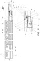
FIG. 12 is a diagram of the slide rail assembly a third retracted state as the second rail is located at an advancing position relative to the first rail according to the embodiment of the present invention, -
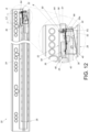
FIG. 13 is a diagram illustrating the first rail is displaced along the first direction from a position as shown inFIG. 12 to drive the blocking portion and the compensating device to block each other for stopping the second rail according to the embodiment of the present invention, -
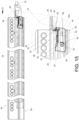
FIG. 14 is a diagram illustrating the first rail is displaced along the first direction from a position as shown inFIG. 13 to drive the first feature to abut against the second feature of the compensating device according to the embodiment of the present invention, -
FIG. 15 is a diagram illustrating the first rail is displaced along the first direction from a position as shown inFIG. 14 to drive the compensating device to move from the first state to the second state for terminating a blocking relation of the blocking portion and the compensating device according to the embodiment of the present invention, and -
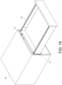
FIG. 16 is a diagram of the slide rail assembly adapted for a furniture according to the embodiment of the present invention. - In the following detailed description of the preferred embodiments, reference is made to the accompanying drawings which form a part hereof, and in which is shown by way of illustration specific embodiments in which the invention may be practiced. In this regard, directional terminology, such as "top", "bottom", "left", "right", "front", "back", etc., is used with reference to the orientation of the Figure(s) being described. The members of the present invention can be positioned in a number of different orientations. As such, the directional terminology is used for purposes of illustration and is in no way limiting. Accordingly, the drawings and descriptions will be regarded as illustrative in nature and not as restrictive. Also, if not specified, the term "connect" is intended to mean either an indirect or direct mechanical connection. Thus, if a first device is connected to a second device, that connection may be through a direct mechanical connection, or through an indirect mechanical connection via other devices and connections.
- As shown in
FIG. 1 andFIG. 2 , aslide rail assembly 20 includes afirst rail 22, asecond rail 24, athird rail 26 and a first aid-sliding device 28. Preferably, theslide rail assembly 20 further includes a second aid-sliding device 30. Thesecond rail 24 is movably mounted between thethird rail 26 and thefirst rail 22, and thefirst rail 22 and thesecond rail 24 are displaceable relative to each other, and/or relative to thethird rail 26 along a longitudinal direction. In this embodiment, by way of example, the longitudinal direction can be defined by a length direction of a slide rail, e.g., thefirst rail 22, thesecond rail 24 or thethird rail 26, and parallel to an X axis. A transverse direction can be defined by a lateral direction or a width direction of the slide rail and parallel to a Y axis. A vertical direction can be defined by a height direction of the slide rail and parallel to a Z axis. - Furthermore, the
second rail 24 is configured to be movably mounted on thethird rail 26, and thefirst rail 22 is configured to be movably mounted on thesecond rail 24. The first aid-sliding device 28 is movably mounted between thefirst rail 22 and thesecond rail 24 for facilitating a relative displacement of thefirst rail 22 and thesecond rail 24. For example, the first aid-slidingdevice 28 includes at least one first rotatingmember 32 configured to be rotatably supported between thefirst rail 22 and thesecond rail 24, and the first rotatingmember 32 can be a roller or a ball. The second aid-sliding device 30 is movably mounted between thesecond rail 24 and thethird rail 26 for facilitating a relative displacement of thesecond rail 24 and thethird rail 26. For example, the second aid-slidingdevice 30 includes at least one second rotatingmember 34 configured to be rotatably supported between thesecond rail 24 and thethird rail 26, and the second rotatingmember 34 can be a roller or a ball. - The
slide rail assembly 20 further includes afirst feature 36 and acompensating device 38. - The
first feature 36 and thecompensating device 38 are arranged on one and the other one of thefirst rail 22 and thesecond rail 24, respectively. In this embodiment, by way of example, thefirst feature 36 is arranged on thefirst rail 22, and thecompensating device 38 is movably mounted on thesecond rail 24. Specifically, thefirst feature 36 can be arranged on thefirst rail 22 directly or indirectly, and the compensatingdevice 38 can be pivotally connected to thesecond rail 24 by ashaft member 40. Preferably, thefirst rail 22 has afirst end portion 22a and asecond end portion 22b located opposite to thefirst end portion 22a, and thesecond rail 24 has afirst end portion 24a and asecond end portion 24b located opposite to thefirst end portion 24a. For example, thefirst end portion 22a and thesecond end portion 22b of thefirst rail 22 are a front end portion and a rear end portion of thefirst rail 22, respectively, and thefirst end portion 24a and thesecond end portion 24b of thesecond rail 24 are a front end portion and a rear end portion of thesecond rail 24, respectively. Preferably, thefirst feature 36 is a protruding structure located adjacent to thefirst end portion 22a of thefirst rail 22, and the compensatingdevice 38 is located arranged adjacent to thefirst end portion 24a of thesecond rail 24. However, the present invention is not limited to this embodiment. - As shown in
FIG. 3 , thethird rail 26 has afirst end portion 26a and asecond end portion 26b located opposite to thefirst end portion 26a. For example, thefirst end portion 26a and thesecond end portion 26b of thethird rail 26 are a front end portion and a rear end portion of thethird rail 26, respectively. Thethird rail 26 includes a supportingsection 42 and a blockingportion 44. The supportingsection 42 extends between thefirst end portion 26a and thesecond end portion 26b of thethird rail 26 along the longitudinal direction and configured to support thesecond rail 24 and/or the compensatingdevice 38. In this embodiment, by way of example, the blockingportion 44 is a protrusion arranged on alateral side 46 of the supportingsection 42 and located adjacent to thefirst end portion 26a of thethird rail 26. However, the present invention is not limited to this embodiment. - As shown in
FIG. 4 and FIG. 5 , the compensatingdevice 38 includes amain body 48, a workingmember 50, apredetermined feature 52, aresilient member 54 and aresilient portion 56. Preferably, the compensatingdevice 38 further includes a recoveringresilient member 58. - The
main body 48 includes a firstmain body portion 60 and a secondmain body portion 62 connected to the firstmain body portion 60. In this embodiment, by way of example, the secondmain body portion 62 is connected to the firstmain body portion 60 in a substantially perpendicular manner. However, the present invention is not limited to this embodiment. Theshaft member 40 passes through the secondmain body portion 62 along the lateral direction or the transverse direction for achieving a pivotal connection of the compensatingdevice 38 and thesecond rail 24. - The working
member 50 is movably mounted on themain body 48. Asecond feature 64 is arranged on the workingmember 50 and configured to cooperate with thefirst feature 36. Preferably, the workingmember 50 is pivotally connected to apredetermined part 68 of the firstmain body portion 60 by a connectingmember 66. Preferably, the workingmember 50 has a first end and a second end located opposite to the first end. For example, the first end and the second end of the workingmember 50 are a front end and a rear end of the workingmember 50, respectively. Preferably, the firstmain body portion 60 includes a blockingwall 70 located adjacent to the first end of the workingmember 50 for stopping the workingmember 50 at a working position K, and an avoiding space adjacent to the second end of the workingmember 50 for allowing the workingmember 50 to move away from the working position K. - As shown in
FIG. 5 , thepredetermined feature 52 is arranged on themain body 48. Thepredetermined feature 52 can be arranged on the secondmain body portion 62 of themain body 48 directly or indirectly. In this embodiment, by way of example, thepredetermined feature 52 can be a protrusion. However, the present invention is not limited to this embodiment. Preferably, themain body 48 has afirst end 48a and asecond end 48b located opposite to thefirst end 48a. For example, thefirst end 48a and thesecond end 48b of themain body 48 are a front end and a rear end of themain body 48, respectively. Preferably, thepredetermined feature 52 is spaced away from thefirst end 48a of themain body 48 by a distance G. - The
resilient member 54 is configured to provide a resilient force to the compensatingdevice 38. In this embodiment, by way of example, a portion of theresilient member 54 is mounted inside a receivingspace 72 of the firstmain body portion 60, and another portion of theresilient member 54 stretches out of the receivingspace 72. - The
resilient portion 56 is arranged on themain body 48. In this embodiment, by way of example, theresilient portion 56 is an extending arm. However, the present invention is not limited to this embodiment. - The recovering
resilient member 58 is configured to provide a recovering resilient force to the workingmember 50, so as to drive the workingmember 50 to move toward the working position K. - When the
slide rail assembly 20 is in a retracted state as shown inFIG. 6 , the compensatingdevice 38 is in a first state S1 in response to the resilient force provided by theresilient member 54, and the workingmember 50 is retained at the working position K in response to the recovering resilient force provided by the recoveringresilient member 58. Besides, as shown inFIG. 6 , at this moment, thesecond feature 64 is spaced away from thefirst feature 36 by a first longitudinal distance L1, and thepredetermined feature 52 is located at a position corresponding to the blockingportion 44 of thethird rail 26, e.g., thepredetermined feature 52 and the blockingportion 44 of thethird rail 26 are aligned with each other along the longitudinal direction. Preferably, as shown inFIG. 6 , at this moment, theresilient member 54 is abutted between themain body 48 and thesecond rail 24, and theresilient portion 56 is located adjacent to thesecond rail 24. However, the present invention is not limited to this embodiment. - Furthermore, when the
slide rail assembly 20 is in the retracted state as shown inFIG. 6 , thefirst rail 22 is located at a retracted position R relative to thethird rail 26. Ideally, when thefirst rail 22 is displaced to the retracted position R, thesecond rail 24 is configured to be displaced to a predetermined position P0 in response to a movement of thefirst rail 22 to the retracted position R. However, after a long-term usage, thesecond rail 24 might be located a position deviated from the predetermined position P0 due to repeated opening movements and retracting movements of thefirst rail 22 and thesecond rail 24 relative to thethird rail 26, an operational mistake, and/or an unexpected external force. - As shown in
FIG. 7 , when thesecond rail 24 is located at a lagging position P1 deviated from the predetermined position P0 relative to thefirst rail 22, thesecond feature 64 is spaced away from thefirst feature 36 by a second longitudinal distance L2 less than the first longitudinal distance L1. - As shown in
FIG. 7 to FIG. 10 , after thesecond rail 24 is displaced to the lagging position P1, thefirst rail 22 displacing along a first direction, e.g., an opening direction D1, from the retracted position R drives thefirst feature 36 and thesecond feature 64 of the compensatingdevice 38 in the first state S1 to abut against each other to drive thesecond rail 24 to synchronously displace together with thefirst rail 22 along the opening direction D1 for a first predetermined distance, e.g., from a first position M1 to a second position M2, so as to compensate a lagging position error, i.e., a deviation between the lagging position P1 and the predetermined position P0, until the compensatingdevice 38 is driven to pivot relative to thethird rail 26 from thefirst state S 1 to a second state S2 along a first pivoting direction R1 by theshaft member 40. In other words, when the compensatingdevice 38 is in the second state S2, a synchronous displacement relation of thesecond rail 24 and thefirst rail 22 is terminated for allowing a further displacement of thefirst rail 22 along the opening direction D1 without any obstruction because thefirst feature 36 does not abut with thesecond feature 64 of the compensatingdevice 38 in the second state S2. Besides, as shown inFIG. 10 , when the compensatingdevice 38 is in the second state S2, theresilient member 54 is resiliently deformed, and theresilient portion 56 is moved away from thesecond rail 24. In addition, as shown inFIG. 10 , when the compensatingdevice 38 is in the second state S2, thepredetermined feature 52 of the compensatingdevice 38 is moved away from the position corresponding to the blockingportion 44 of thethird rail 26, e.g., thepredetermined feature 52 of the compensatingdevice 38 is misaligned with the blockingportion 44 of thethird rail 26 along the longitudinal direction. In other words, when the compensatingdevice 38 is in the second state S2, a blocking relation of the blockingportion 44 of thethird rail 26 and thepredetermined feature 52 of the compensatingdevice 38 is prevented for allowing a further displacement of thesecond rail 24 along the opening direction D1 without any obstruction because thepredetermined feature 52 of the compensatingdevice 38 is misaligned with the blockingportion 44 of thethird rail 26 along the longitudinal direction. - Preferably, one of the
first feature 36 and thesecond feature 64 includes a first guidingportion 74. For example, the first guidingportion 74 can be an inclined surface or an arc surface. In this embodiment, by way of example, thefirst feature 36 includes the first guidingportion 74. However, the present invention is not limited to this embodiment. When thesecond rail 24 is synchronously displaced together with thefirst rail 22 along the opening direction D1 relative to thethird rail 26 from the first position M1 as shown inFIG. 8 to the second position M2 as shown inFIG. 9 , the compensatingdevice 38 is displaced along the supportingsection 42 of thethird rail 26 to exceed thefirst end portion 26a of thethird rail 26. After the compensatingdevice 38 exceeds thefirst end portion 26a of thethird rail 26, the compensatingdevice 38 is free to be driven to move from thefirst state S 1 as shown inFIG. 9 to the second state S2 as shown inFIG. 10 along the first pivoting direction R1 by an abutment of the first guidingportion 74 and thesecond feature 64. - Preferably, a guiding
section 76 is formed on a connection of the supportingsection 42 and thefirst end portion 26a of thethird rail 26 for facilitating the compensatingdevice 38 to move from the first state S1 to the second state S2 relative to thethird rail 26. For example, the guidingsection 76 can be a chamfer edge. - As shown in
FIG. 11 , after the synchronous displacement relation of thesecond rail 24 and thefirst rail 22 is terminated and the blocking relation of the blockingportion 44 of thethird rail 26 and thepredetermined feature 52 of the compensatingdevice 38 is prevented, thefirst rail 22 and thesecond rail 24 can be displaced relative to thethird rail 26 along the opening direction D1 individually, so as to switch theslide rail assembly 20 to an extended state as shown inFIG. 11 by locating thefirst rail 22 at an extended position E, e.g., a fully extended position. When theslide rail assembly 20 is in the extended state, i.e., thefirst rail 22 is located at the extended position E, thefirst end portion 22a of thefirst rail 22 and thefirst end portion 24a of thesecond rail 24 exceed thefirst end portion 24a of thesecond rail 24 and thefirst end portion 26a of thethird rail 26, respectively. - Preferably, when the
slide rail assembly 20 moves from a state as shown inFIG. 10 to the extended state as shown inFIG. 11 , the compensatingdevice 38 moves from the second state S2 as shown inFIG. 10 to the first state S1 as shown inFIG. 11 along a second pivoting direction R2 opposite to the first pivoting direction R1 in response to the resilient force provided by theresilient member 54. When the compensatingdevice 38 moves from the second state S2 to the first state S1, theresilient portion 56 is configured to abut against thesecond rail 24 for providing a noise-reducing effect and/or an impact-buffering effect. - It should be noticed that after compensation of the deviation between the lagging position P1 and the predetermined position P0 is achieved, the
second rail 24 can be driven to displace back to the predetermined position P0 as shown inFIG. 6 rather than the lagging position P1 in response to a displacement of thefirst rail 22 from the extended position E to the retracted position R along a second direction, e.g., a retracting direction D2. - As shown in
FIG. 12 , when thesecond rail 24 is located at an advancing position P2 deviated from the predetermined position P0 relative to thefirst rail 22, thesecond feature 64 is spaced away from thefirst feature 36 by a third longitudinal distance L3 greater than the first longitudinal distance L1. - As shown in
FIG. 12 to FIG. 15 , after thesecond rail 24 is displaced to the advancing position P2, thefirst rail 22 displacing along the opening direction D1 from the retracted position R drives the blockingportion 44 of thethird rail 26 and thepredetermined feature 52 of the compensatingdevice 38 in the first state S1 to block each other to stop thesecond rail 24, so as to compensate an advancing position error, i.e., a deviation between the advancing position P2 and the predetermined position P0, until thefirst rail 22 is displaced along the opening direction D1 over a second predetermined distance, e.g., a distance N from a position as shown inFIG. 13 to a position as shown inFIG. 14 , to drive thefirst feature 36 and thesecond feature 64 of the compensatingdevice 38 in the first state S1 to abut against each other to drive the compensatingdevice 38 to pivot from the first state S1 to the second state S2 along the first pivoting direction R1 by theshaft member 40. In other words, when the compensatingdevice 38 is in the second state S2, the blockingportion 44 of thethird rail 26 does not block thepredetermined feature 52 of the compensatingdevice 38. - As shown in
FIG. 15 , when the compensatingdevice 38 is in the second state S2, thefirst feature 36 is not blocked by thesecond feature 64 of the compensatingdevice 38 for allowing a further displacement of thefirst rail 22 along the opening direction D1. In addition, as shown inFIG. 15 , when the compensatingdevice 38 is in the second state S2, thepredetermined feature 52 of the compensatingdevice 38 is moved away from the position corresponding to the blockingportion 44 of thethird rail 26, e.g., thepredetermined feature 52 of the compensatingdevice 38 is misaligned with the blockingportion 44 of thethird rail 26 along the longitudinal direction, such that the blocking relation of the blockingportion 44 of thethird rail 26 and thepredetermined feature 52 of the compensatingdevice 38 is terminated, for allowing a further displacement of thesecond rail 24 along theopening direction D 1. Furthermore, as shown inFIG. 15 , when the compensatingdevice 38 is in the second state S2, theresilient member 54 is resiliently deformed, and theresilient portion 56 is moved away from thesecond rail 24. - Preferably, as shown in
FIG. 14 , when the blockingportion 44 of thethird rail 26 blocks thepredetermined feature 52 of the compensatingdevice 38, the compensatingdevice 38 exceeds thefirst end portion 26a of thethird rail 26, such that the compensatingdevice 38 can be driven to move from the first state S1 as shown inFIG. 14 to the second state S2 as shown inFIG. 15 along the first pivoting direction R1 by an abutment of the first guidingportion 74 and thesecond feature 64. - Besides, as shown in
FIG. 15 , after the blocking relation of the blockingportion 44 of thethird rail 26 and thepredetermined feature 52 of the compensatingdevice 38 is terminated, thefirst rail 22 and thesecond rail 24 can be displaced relative to thethird rail 26 along the opening direction D1 individually to switch theslide rail assembly 20 in the extended state as shown inFIG. 11 by locating thefirst rail 22 at the extended position E. - Preferably, when the
slide rail assembly 20 moves from a state as shown inFIG. 15 to the extended state as shown inFIG. 11 , the compensatingdevice 38 moves from the second state S2 as shown inFIG. 15 to the first state S1 as shown inFIG. 11 along the second pivoting direction R2 in response to the resilient force provided by theresilient member 54. When the compensatingdevice 38 moves from the second state S2 to the first state S1, theresilient portion 56 is configured to abut against thesecond rail 24 for providing a noise-reducing effect and/or an impact-buffering effect. - It should be noticed that after compensation of the deviation between the advancing position P2 and the predetermined position P0 is achieved, the
second rail 24 can be driven to displace back to the predetermined position P0 as shown inFIG. 6 rather than the advancing position P2 in response to the displacement of thefirst rail 22 from the extended position E to the retracted position R along the retracting direction D2. - Preferably, one of the
first feature 36 and thesecond feature 64 includes asecond guiding portion 78. For example, the second guidingportion 78 can be an inclined surface or an arc surface. In this embodiment, by way of example, thefirst feature 36 includes the second guidingportion 78, and the second guidingportion 78 is located opposite to the first guidingportion 74. Preferably, the first guidingportion 74 and the second guidingportion 78 are located adjacent to a front side and a rear side of thefirst feature 36. However, the present invention is not limited to this embodiment. When thefirst rail 22 is displaced from the extended position E to the retraced position R, the second guidingportion 78 is configured to abut against the workingmember 50 to drive the workingmember 50 to pivot away from the working position K along a predetermined pivoting direction r, so as to allow thefirst feature 36 to pass over the workingmember 50 along the retracting direction D2. After thefirst feature 36 passes over the workingmember 50 along the retracting direction D2, the workingmember 50 can pivot back to the working position K in response to the recovering resilient force provided by the recoveringresilient member 58. - As shown in
FIG. 11 andFIG. 16 , theslide rail assembly 20 can be adapted for a furniture. For example, there can be twoslide rail assemblies 20 mounted between adrawer 82 and acabinet body 80 symmetrically for facilitating a movement of thedrawer 82 relative to thecabinet body 80. Specifically, thethird rail 26 of each of the twoslide rail assemblies 20 is configured to be mounted on thecabinet body 80, and thefirst rail 22 of each of the twoslide rail assemblies 20 is configured to be support thedrawer 82. - In conclusion, the
slide rail assembly 20 includes the following characteristics. - 1. The
slide rail assembly 20 is capable of compensating an error of a relative position of at least two slide rails, e.g., thefirst rail 22 and thesecond rail 24, by utilizing the compensatingdevice 38. - 2. No matter whether the
second rail 24 is located at the lagging position P1, the advancing position P2 or the predetermined position P0, thefirst rail 22 displacing along the opening direction D1 from the retracted position R drives thefirst feature 36 and thesecond feature 64 of the compensatingdevice 38 in the first state S1 to abut against each other until the compensatingdevice 38 is driven to move from the first state S1 to the second state S2. - 3. When the compensating
device 38 moves from the second state S2 to the first state S1, theresilient portion 56 is configured to abut against thesecond rail 24 for providing a noise-reducing effect and/or an impact-buffering effect. - Those skilled in the art will readily observe that numerous modifications and alterations of the device and method may be made while retaining the teachings of the invention. Accordingly, the above disclosure should be construed as limited only by the metes and bounds of the appended claims.
Claims (15)
- A slide rail assembly (20) comprising:a first rail (22) displaceable along a first direction or a second direction opposite to the first direction;a second rail (24);characterized by:a first feature (36) arranged on the first rail (22);a compensating device (38) mounted on the second rail (24) and movable between a first state (S1) and a second state (S2), the compensating device (38) comprising a second feature (64); anda third rail (26), the second rail (24) being movably mounted on the third rail (26), the third rail (26) comprising a supporting section (42) and a blocking portion (44), and the supporting section (42) being configured to support the second rail (24) or the compensating device (38);wherein after the second rail (24) is displaced to an advancing position (P2) relative to the first rail (22), the first rail (22) displacing along a first direction drives the blocking portion (44) of the third rail (26) and the compensating device (38) in the first state (S1) to block each other to stop the second rail (24) until the first rail (22) is displaced along the first direction over a predetermined distance to drive the first feature (36) and the compensating device (38) in the first state (S1) to abut against each other to drive the compensating device (38) to move from the first state (S1) to the second state (S2), and when the compensating device (38) is in the second state (S2), the blocking portion (44) of the third rail (26) does not block the compensating device (38).
- The slide rail assembly (20) of claim 1, further characterized by:a first aid-sliding device (28) comprising at least one first rotating member (32) configured to be rotatably supported between the first rail (22) and the second rail (24); anda second aid-sliding device (30) comprising at least one second rotating member (34) rotatably supported between the second rail (24) and the third rail (26).
- The slide rail assembly (20) of any of claims 1 and 2, characterized in that after the second rail (24) is displaced to a lagging position (P1) relative to the first rail (22), the first rail (22) displacing along the first direction drives the first feature (36) and the second feature (64) of the compensating device (38) in the first state (S1) to abut against each other, so as to drive the second rail (24) to synchronously displace together with the first rail (22) along the first direction for another predetermined distance until the compensating device (38) is driven to move from the first state (S1) to the second state (S2).
- The slide rail assembly (20) of any of claims 1 to 3, characterized in that the compensating device (38) is pivotally connected to the second rail (24).
- The slide rail assembly (20) of any of claim 3 and 4, characterized in that one of the first feature (36) and the second feature (64) comprises a first guiding portion (74), the compensating device (38) further comprises a predetermined feature (52), after the second rail (24) is displaced to the advancing position (P2) relative to the first rail (22), the first rail (22) displacing along the first direction drives the blocking portion (44) of the third rail (26) and the predetermined feature (52) of the compensating device (38) in the first state (S1) to block each other to stop the second rail (24) until the first rail (22) is displaced along the first direction over the predetermined distance to drive the first feature (36) and the second feature (64) of the compensating device (38) in the first state (S1) to abut against each other by the first guiding portion (74), so as to drive the compensating device (38) to move from the first state (S1) to the second state (S2), and when the compensating device (38) is in the second state (S2), the blocking portion (44) of the third rail (26) does not block the predetermined feature (52) of the compensating device (38).
- The slide rail assembly (20) of any of claims 1 to 5, wherein the compensating device (38) further comprises a main body (48) and a working member (50), the working member (50) is movably mounted on the main body (48), and the second feature (64) is arranged on the working member (50).
- The slide rail assembly (20) of claim 6, characterized in that the compensating device (38) further comprises a recovering resilient member (58), the one or another one of the first feature (36) and the second feature (64) further comprises a second guiding portion (78), during a displacement of the first rail (22) along the second direction, the first feature (36) and the second feature (64) of the compensating device (38) in the first state (S1) abut against each other by the second guiding portion (78) to drive the working member (50) to move away from a working position (K) for allowing the first feature (36) to pass over the working member (50) along the second direction, and after the first feature (36) passes over the working member (50), the working member (50) moves to the working position (K) in response to a recovering resilient force provided by the recovering resilient member (58).
- The slide rail assembly (20) of any of claims 6 and 7, characterized in that the working member (50) is pivotally connected to the main body (48).
- The slide rail assembly (20) of any of claims 1 to 8, characterized in that the compensating device (38) further comprises a resilient member (54), and the compensating device (38) moves from the second state (S2) to the first state (S1) in response to a resilient force provided by the resilient member (54).
- The slide rail assembly (20) of any of claims 1 to 9, characterized in that the compensating device (38) further comprises a resilient portion (56) configured to abut against the second rail (24) when the compensating device (38) moves from the second state (S2) to the first state (S1).
- The slide rail assembly (20) of any of claims 3 to 10, characterized in that the lagging position (P1) and the advancing position (P2) are deviated from a predetermined position (P0), when the second rail (24) is located at the predetermined position (P0) relative to the first rail (22), the second feature (64) is spaced away from the first feature (36) by a first longitudinal distance (L1), when the second rail (24) is located at the lagging position (P1) deviated from the predetermined position (P0) relative to the first rail (22), the second feature (64) is spaced away from the first feature (36) by a second longitudinal distance (L2) less than the first longitudinal distance (L1), and when the second rail (24) is located at the advancing position (P2) deviated from the predetermined position (P0) relative to the first rail (22), the second feature (64) is spaced away from the first feature (36) by a third longitudinal distance (L3) greater than the first longitudinal distance (L1).
- The slide rail assembly (20) of any of claims 1 to 2, characterized in that the advancing position (P2) are deviated from a predetermined position (P0), when the second rail (24) is located at the predetermined position (P0) relative to the first rail (22), the second feature (64) is spaced away from the first feature (36) by a first longitudinal distance (L1), and when the second rail (24) is located at the advancing position (P2) deviated from the predetermined position (PO) relative to the first rail (22), the second feature (64) is spaced away from the first feature (36) by a third longitudinal distance (L3) greater than the first longitudinal distance (L1).
- The slide rail assembly (20) of any of claims 1 to 12, characterized in that the third rail (26) is configured to be mounted on a cabinet body (80), and the first rail (22) is configured to support a drawer (82).
- The slide rail assembly (20) of any of claims 1 to 13, characterized in that the first direction is an opening direction (D1), and the second direction is a retracting direction (D2).
- The slide rail assembly (20) of any of claims 1 to 14, characterized in that the second rail (24) is movably mounted between the third rail (26) and the first rail (22).
Applications Claiming Priority (1)
| Application Number | Priority Date | Filing Date | Title |
|---|---|---|---|
| TW112135589A TWI834591B (en) | 2023-09-15 | 2023-09-15 | Slide rail assembly |
Publications (1)
| Publication Number | Publication Date |
|---|---|
| EP4523567A1 true EP4523567A1 (en) | 2025-03-19 |
Family
ID=91128056
Family Applications (1)
| Application Number | Title | Priority Date | Filing Date |
|---|---|---|---|
| EP24175888.7A Pending EP4523567A1 (en) | 2023-09-15 | 2024-05-15 | Slide rail assembly |
Country Status (3)
| Country | Link |
|---|---|
| EP (1) | EP4523567A1 (en) |
| JP (1) | JP7782774B2 (en) |
| TW (1) | TWI834591B (en) |
Citations (3)
| Publication number | Priority date | Publication date | Assignee | Title |
|---|---|---|---|---|
| EP3058847A1 (en) * | 2015-02-18 | 2016-08-24 | King Slide Works Co., Ltd. | Slide rail assembly |
| US11013320B2 (en) * | 2017-08-17 | 2021-05-25 | Julius Blum Gmbh | Drawer pull-out guide |
| US11272784B2 (en) | 2017-08-17 | 2022-03-15 | Julius Blum Gmbh | Drawer pull-out guide |
Family Cites Families (3)
| Publication number | Priority date | Publication date | Assignee | Title |
|---|---|---|---|---|
| AT505120B1 (en) * | 2007-05-07 | 2012-04-15 | Blum Gmbh Julius | EXTRACTION GUIDE FOR DRAWERS |
| TWI611747B (en) * | 2016-10-12 | 2018-01-11 | 川湖科技股份有限公司 | Bracket device |
| US10736422B2 (en) * | 2018-10-04 | 2020-08-11 | King Slide Works Co., Ltd. | Slide rail assembly |
-
2023
- 2023-09-15 TW TW112135589A patent/TWI834591B/en active
-
2024
- 2024-05-15 EP EP24175888.7A patent/EP4523567A1/en active Pending
- 2024-05-16 JP JP2024080001A patent/JP7782774B2/en active Active
Patent Citations (3)
| Publication number | Priority date | Publication date | Assignee | Title |
|---|---|---|---|---|
| EP3058847A1 (en) * | 2015-02-18 | 2016-08-24 | King Slide Works Co., Ltd. | Slide rail assembly |
| US11013320B2 (en) * | 2017-08-17 | 2021-05-25 | Julius Blum Gmbh | Drawer pull-out guide |
| US11272784B2 (en) | 2017-08-17 | 2022-03-15 | Julius Blum Gmbh | Drawer pull-out guide |
Also Published As
| Publication number | Publication date |
|---|---|
| JP7782774B2 (en) | 2025-12-09 |
| JP2025043256A (en) | 2025-03-28 |
| US20250089892A1 (en) | 2025-03-20 |
| TW202512973A (en) | 2025-04-01 |
| TWI834591B (en) | 2024-03-01 |
Similar Documents
| Publication | Publication Date | Title |
|---|---|---|
| US11246410B2 (en) | Slide rail assembly | |
| EP4489537B1 (en) | Slide rail mechanism | |
| EP4570126A1 (en) | Slide rail assembly | |
| EP4477823A1 (en) | Interlock kit and related furniture assembly | |
| US12203292B2 (en) | Slide rail mechanism | |
| EP4741611A1 (en) | Slide rail mechanism | |
| EP4501174A1 (en) | Slide rail assembly | |
| EP4417088A1 (en) | Slide rail mechanism | |
| US12628950B2 (en) | Slide rail assembly | |
| US20250089892A1 (en) | Slide rail assembly | |
| EP4393349A1 (en) | Slide rail assembly | |
| EP4461160A1 (en) | Furniture assembly | |
| US12390008B2 (en) | Slide rail mechanism | |
| EP4403732A1 (en) | Slide rail mechanism | |
| EP4736711A1 (en) | Slide rail assembly | |
| CN112754197B (en) | Slide rail assembly | |
| CN210643259U (en) | Slide rail damping self-locking structure | |
| EP4529372A1 (en) | Slide rail assembly | |
| EP4635366B1 (en) | Slide rail assembly | |
| CN119655584B (en) | Sliding rail assembly | |
| JP2026085216A (en) | Slide rail mechanism | |
| JP2026079670A (en) | Slide rail assembly | |
| CN119981544A (en) | Lock structure and double door system including the same |
Legal Events
| Date | Code | Title | Description |
|---|---|---|---|
| PUAI | Public reference made under article 153(3) epc to a published international application that has entered the european phase |
Free format text: ORIGINAL CODE: 0009012 |
|
| STAA | Information on the status of an ep patent application or granted ep patent |
Free format text: STATUS: REQUEST FOR EXAMINATION WAS MADE |
|
| 17P | Request for examination filed |
Effective date: 20250207 |
|
| AK | Designated contracting states |
Kind code of ref document: A1 Designated state(s): AL AT BE BG CH CY CZ DE DK EE ES FI FR GB GR HR HU IE IS IT LI LT LU LV MC ME MK MT NL NO PL PT RO RS SE SI SK SM TR |
|
| STAA | Information on the status of an ep patent application or granted ep patent |
Free format text: STATUS: EXAMINATION IS IN PROGRESS |
|
| 17Q | First examination report despatched |
Effective date: 20250620 |