EP4521809A1 - A method for configuring orthogonal channel noise generation over l2-l1 interface - Google Patents
A method for configuring orthogonal channel noise generation over l2-l1 interface Download PDFInfo
- Publication number
- EP4521809A1 EP4521809A1 EP24198907.8A EP24198907A EP4521809A1 EP 4521809 A1 EP4521809 A1 EP 4521809A1 EP 24198907 A EP24198907 A EP 24198907A EP 4521809 A1 EP4521809 A1 EP 4521809A1
- Authority
- EP
- European Patent Office
- Prior art keywords
- ocn
- ocnsconfig
- layer
- module
- information
- Prior art date
- Legal status (The legal status is an assumption and is not a legal conclusion. Google has not performed a legal analysis and makes no representation as to the accuracy of the status listed.)
- Pending
Links
- 238000000034 method Methods 0.000 title claims abstract description 27
- 125000001651 cyanato group Chemical group [*]OC#N 0.000 claims abstract description 18
- 230000005540 biological transmission Effects 0.000 claims abstract description 7
- 238000012360 testing method Methods 0.000 claims abstract description 5
- 238000005259 measurement Methods 0.000 description 2
- 238000012986 modification Methods 0.000 description 2
- 230000004048 modification Effects 0.000 description 2
- 238000004088 simulation Methods 0.000 description 2
- 238000013507 mapping Methods 0.000 description 1
- 238000005457 optimization Methods 0.000 description 1
Images

Classifications
-
- H—ELECTRICITY
- H04—ELECTRIC COMMUNICATION TECHNIQUE
- H04W—WIRELESS COMMUNICATION NETWORKS
- H04W24/00—Supervisory, monitoring or testing arrangements
- H04W24/08—Testing, supervising or monitoring using real traffic
-
- H—ELECTRICITY
- H04—ELECTRIC COMMUNICATION TECHNIQUE
- H04W—WIRELESS COMMUNICATION NETWORKS
- H04W24/00—Supervisory, monitoring or testing arrangements
- H04W24/06—Testing, supervising or monitoring using simulated traffic
Definitions
- the present disclosure is related to 4G, 5G New Radio (NR) and 6G wireless networks, and relates more particularly to Orthogonal Channel Noise (OCN) generation.
- OFC Orthogonal Channel Noise
- Orthogonal Channel Noise simulator provides a dummy load generation for the unused resource elements (REs) of a carrier.
- Orthogonal Channel Noise (OCN) is used for simulating a loaded cell conditions in the field or in a lab when the available Physical Resource Blocks (PRBs) are not fully utilized by the connected users at a given time. This can be used by network operators or test labs to simulate a fully loaded cell site conditions even when there are not many real customers..
- OCN can be used to simulate a fully loaded cell condition, thereby enabling checking of the performance of the Open Radio Access Network Radio Unit (O-RU) in the scenario when cells are not actually fully loaded.
- Basic performance impacts at full transmission (TX) power and passive intermodulation (PIM) impacts can be verified in the field environment. This is useful for radio frequency (RF) optimizations under loaded conditions, without requiring actual user loading.
- RF radio frequency
- Layer2 (L2) needs to send configuration to Layer1 (L1), which in turn will send it to the O-RU.
- FIG. 1 illustrates an example cell deployment scenario for usage of OCNs.
- FIG. 1 shows seven cells, i.e., Cell 1 through Cell 7. If interference on Cell 1 due to other neighboring cells (i.e., Cell 2 through Cell 7) needs to be measured, then Cell 2 through Cell 7 will be configured with OCNs parameters, if these cells are not loaded fully. This will cause maximum interference possible on Cell 1, and hence even without real user equipments (UEs) present, loading conditions can be verified.
- UEs real user equipments
- the present disclosure provides interface improvements in L2-to-L1 transmission to carry the information of PRBs, power, etc., that has to be considered for interference measurement. This information will be passed only in downlink direction, hence changes are proposed in Downlink Transmission Time Interval request (DL_TTI.request) message in SCF FAPI standard.
- DL_TTI.request Downlink Transmission Time Interval request
- the OCNs parameters are sent from L2 to L1, and based on the received parameters, L1 can configure the RU and implement the fully-loaded scenario for a neighboring cell which is measuring the interference.
- L2 and L1 can be implemented as software modules running on DU (e.g., O-DU) component of gNodeB (gNB).
- DU e.g., O-DU
- gNB gNodeB
- the OCNs parameters are sent from L2 to L1, and based on the received parameters, L1 can configure the RU and implement the fully-loaded scenario for a neighboring cell which is measuring the interference.
- L2 and L1 can be implemented as software modules running on DU (e.g., O-DU) component of gNodeB (gNB).
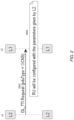
- FIG. 2 illustrates an example method of implementing OCNs configuration involving L2 and L1.
- L2 21 sends DL_TTI.request message (protocol data unit (PDU) type being OCNs) to L1 22.
- PDU protocol data unit
- L1 22 will configure the RU (e.g., O-RU) with OCNs configuration parameters contained in the DL_TTI.request message.
- the DL_TTI.request message structure (shown below) is modified to contain OCNs configuration parameters to be transmitted from L2 to L1:
- DL_TTI.request Field Type Description isOCNsConfigured Uint8_t Indicates if OCN configuration is sent in DL_TTI.Request.
- True next structure containing the OCNs parameter will be present.
- L1 need to decode the same and configure RU accordingly. False: OCNs parameters are not present hence next structure will be missing.
- OCNsConfig Structure Contains the OCNs parameters. Structure is defined below in Errore. L'origine riferimento non è stata trovata . structure.
- OCNConfig structure Components of OCNsConfig structure (included in the DL_TTI.request message) is shown in Table 1 below: TABLE 1: OCNConfig structure Field Type Each BWPPart information nrOfBwpPart uint8_t Number of bandwidth parts (BWPs) in which OCNs needs to be monitored. Value: 1 -> 8 For each Bwp Part ⁇ bwp-Size uint16_t this field signals the bandwidth part (BWP) size, e.g., as per 3GPP TS 38.213, sec 12. Number of contiguous PRBs allocated to the BWP.
- BWP bandwidth part
- 3GPP TS 38.212 section 7.3.1.2.2 bitmap of RBs, 273 rounded up to multiple of 32. This bitmap is in units of virtual resource blocks (VRBs). Least significant bit (LSB) of byte 0 of the bitmap represents the VRB 0, as per section 7.3.1.6 of 3GPP TS 38.211. startSymbollndex uint8_t Start symbol index of PDSCH mapping from the start of the slot, S. As per 3GPP TS 38.214, Table 5.1.2.1-1. Value: 0->13 Field Type nrOfSymbols uint8_t PDSCH duration in symbols, L.
- LSB least significant bit
- Precoding and Beamforming structure See, e.g., Table 3-93 of SCF FAPI v7. If the PHY supports Rel-16 see also Table 3-94 of SCF FAPI v7. For PHYs supporting FAPIv4 MU-MIMO groups, see also Table 3-95 of SCF FAPI v7. Can include specific beamforming weights and beam identifier (ID) to be applied for OCN signals on specified PRBs. powerControlOffsetProfileNR uint8_t Ratio of PDSCH EPRE to NZP CSI-RS EPRE. As per 3GPP TS 38.214, sec 5.2.2.3.1.
- L1 is configured with ProfileSSS powerControlOffsetSSProfileNR uint8_t Ratio of NZP CSI-RS EPRE to SSB/PBCH block EPRE.
- the example method according to the present disclosure enables simulation testing of wireless networks for fully loaded conditions even when actual UEs are present, which simulation testing will not require any changes in the 3GPP-defined procedures.
Landscapes
- Engineering & Computer Science (AREA)
- Computer Networks & Wireless Communication (AREA)
- Signal Processing (AREA)
- Mobile Radio Communication Systems (AREA)
Abstract
A method of implementing Orthogonal Channel Noise (OCN) testing in a wireless network for fully loaded conditions in the absence of actual user equipment (UE) loads, said wireless network including a radio unit (RU), a Layer 1 module, and a Layer 2 module connected to the Layer 1 module over a message-based interface, the method comprising: sending, by the Layer 2 module, OCN parameters to the Layer 1 module via a Downlink Transmission Time Interval request (DL_TTI.request) message; and configuring, by the Layer 1 module, the RU using the OCN parameters. In the method, i) the DL_TTI.request message contains isOCNsConfigured parameter; and ii) in the case the isOCNsConfigured parameter is set to TRUE, then the DL_TTI.Request message additionally contains OCNs configuration (OCNsConfig) information.
Description
- The present disclosure is related to 4G, 5G New Radio (NR) and 6G wireless networks, and relates more particularly to Orthogonal Channel Noise (OCN) generation.
- Orthogonal Channel Noise simulator provides a dummy load generation for the unused resource elements (REs) of a carrier. Orthogonal Channel Noise (OCN) is used for simulating a loaded cell conditions in the field or in a lab when the available Physical Resource Blocks (PRBs) are not fully utilized by the connected users at a given time. This can be used by network operators or test labs to simulate a fully loaded cell site conditions even when there are not many real customers..
- OCN can be used to simulate a fully loaded cell condition, thereby enabling checking of the performance of the Open Radio Access Network Radio Unit (O-RU) in the scenario when cells are not actually fully loaded. Basic performance impacts at full transmission (TX) power and passive intermodulation (PIM) impacts can be verified in the field environment. This is useful for radio frequency (RF) optimizations under loaded conditions, without requiring actual user loading. For simulating conditions at the O-RU, Layer2 (L2) needs to send configuration to Layer1 (L1), which in turn will send it to the O-RU.
-
FIG. 1 illustrates an example cell deployment scenario for usage of OCNs.FIG. 1 shows seven cells, i.e.,Cell 1 throughCell 7. If interference onCell 1 due to other neighboring cells (i.e., Cell 2 through Cell 7) needs to be measured, then Cell 2 throughCell 7 will be configured with OCNs parameters, if these cells are not loaded fully. This will cause maximum interference possible onCell 1, and hence even without real user equipments (UEs) present, loading conditions can be verified. - Current structures defined in Small Cell Forum (SCF) Functional Application Platform Interface (FAPI) standard v7 document does not have any information for OCNs configuration so that physical layer (PHY) can simulate the loading conditions on the RU, e.g., which physical resource block (PRB) is to be considered as loaded, etc., even when UEs are not actually present.
- Therefore, a need exists to provide interface improvements in L2-to-L1 transmission to carry the information of PRBs, power, etc., that has to be considered for interference measurement.
- The present disclosure provides interface improvements in L2-to-L1 transmission to carry the information of PRBs, power, etc., that has to be considered for interference measurement. This information will be passed only in downlink direction, hence changes are proposed in Downlink Transmission Time Interval request (DL_TTI.request) message in SCF FAPI standard.
- In an example embodiment according to the present disclosure, the OCNs parameters are sent from L2 to L1, and based on the received parameters, L1 can configure the RU and implement the fully-loaded scenario for a neighboring cell which is measuring the interference.
- In an example embodiment according to the present disclosure, L2 and L1 can be implemented as software modules running on DU (e.g., O-DU) component of gNodeB (gNB).
-
-
FIG. 1 illustrates an example cell deployment scenario for usage of OCNs. -
FIG. 2 illustrates an example method of implementing OCNs configuration involving L2 and L1. - In an example embodiment according to the present disclosure, the OCNs parameters are sent from L2 to L1, and based on the received parameters, L1 can configure the RU and implement the fully-loaded scenario for a neighboring cell which is measuring the interference. As an example, L2 and L1 can be implemented as software modules running on DU (e.g., O-DU) component of gNodeB (gNB).
-
FIG. 2 illustrates an example method of implementing OCNs configuration involving L2 and L1. As referenced by theprocess arrow 2001,L2 21 sends DL_TTI.request message (protocol data unit (PDU) type being OCNs) toL1 22. Next, referenced by 2002,L1 22 will configure the RU (e.g., O-RU) with OCNs configuration parameters contained in the DL_TTI.request message. - According to an example embodiment, the DL_TTI.request message structure (shown below) is modified to contain OCNs configuration parameters to be transmitted from L2 to L1:
DL_TTI.request:Field Type Description isOCNsConfigured Uint8_t Indicates if OCN configuration is sent in DL_TTI.Request. True: next structure containing the OCNs parameter will be present. L1 need to decode the same and configure RU accordingly. False: OCNs parameters are not present hence next structure will be missing. OCNsConfig Structure Contains the OCNs parameters. Structure is defined below in Errore. L'origine riferimento non è stata trovata. structure. - Components of OCNsConfig structure (included in the DL_TTI.request message) is shown in Table 1 below:
TABLE 1: OCNConfig structure Field Type Each BWPPart information nrOfBwpPart uint8_t Number of bandwidth parts (BWPs) in which OCNs needs to be monitored. Value: 1 -> 8 For each Bwp Part{ bwp-Size uint16_t this field signals the bandwidth part (BWP) size, e.g., as per 3GPP TS 38.213, sec 12. Number of contiguous PRBs allocated to the BWP. Value: 1->275 bwp-Start Uint16_t this field signals the bandwidth part start RB index from reference CRB, as per 3GPP TS 38.213, sec. 12. Value: 0->274 subcarrierSpacing uint8_t subcarrierSpacing, e.g., as per 3GPP TS 38.211, sec 4.2. Value:0->4 Modulation Uint8_t Modulation scheme to be used. Value 0 → QPSK 1 → 16 QAM 2 → 64 QAM 3 → 256 QAM rb-Bitmap uint8_t [36] This parameter is an array of type Uint8 which has 36 elements, i.e., 36 *8 = 288 bits. 3GPP TS 38.212, section 7.3.1.2.2 bitmap of RBs, 273 rounded up to multiple of 32. This bitmap is in units of virtual resource blocks (VRBs). Least significant bit (LSB) of byte 0 of the bitmap represents the VRB 0, as per section 7.3.1.6 of 3GPP TS 38.211. startSymbollndex uint8_t Start symbol index of PDSCH mapping from the start of the slot, S. As per 3GPP TS 38.214, Table 5.1.2.1-1. Value: 0->13 Field Type nrOfSymbols uint8_t PDSCH duration in symbols, L. As per 3GPP TS 38.214, Table 5.1.2.1-1 Value: 1->14 Precoding and Beamforming structure See, e.g., Table 3-93 of SCF FAPI v7. If the PHY supports Rel-16 see also Table 3-94 of SCF FAPI v7. For PHYs supporting FAPIv4 MU-MIMO groups, see also Table 3-95 of SCF FAPI v7. Can include specific beamforming weights and beam identifier (ID) to be applied for OCN signals on specified PRBs. powerControlOffsetProfileNR uint8_t Ratio of PDSCH EPRE to NZP CSI-RS EPRE. As per 3GPP TS 38.214, sec 5.2.2.3.1. Values: 0->23: representing -8 to 15 dB in 1dB steps 255: L1 is configured with ProfileSSS powerControlOffsetSSProfileNR uint8_t Ratio of NZP CSI-RS EPRE to SSB/PBCH block EPRE. As per 3GPP TS 38.214, sec 5.2.2.3.1 Values: 0: -3dB, 1: 0dB, 2: 3dB, 3: 6dB 255: L1 is configured with ProfileSSS } - Shown below is an example involving four slots for PDSCH and OCNs configuration sent from L2 to L1:
60% Loaded 10% Loaded No Scheduling RBs Slot0 Slot1 Slot2 Slot3 0 1 2 PDSCH 3 4 5 6 7 8 9 10 11 12 PDSCH 13 14 PDSCH 15 16 17 18 19 20 21 22 23 OCNS OCNS OCNS 24 RBs RBs OCNS RBs - In this example, 25 PRBs (RB0 to RB24) are assumed to be available for PDSCH transmission, and Slot 0 through
Slot 3 are scheduled as follows: - A) Slot 0:
- PDSCH is scheduled for first 60% of resources (15 RBs, i.e., RB0 to RB14, on all 13 symbols).
- RBBitmap in OCNsConfig will be set from RB15 to RB 24 on all 13 symbols for loading.
- B) Slot 1:
- PDSCH is scheduled for first 12% of available resources (3 RBs, i.e., RB0 to RB2, on all 13 symbols).
- RBBitmap in OCNsConfig will be set from RB3 to RB24 on all 13 symbols to make it fully loaded condition.
- C) Slot 2:
No PDSCH is scheduled, hence RBBitmap in OCNsConfig will be set from RB0 to RB 24 on all 13 symbols for simulating fully loaded condition. - D) Slot 3:
- PDSCH is scheduled for 52% of available resources (13 RBs, RB0 to RB12, on all 13 symbols).
- RBBitmap in OCNsConfig will be set from RB13 to RB24 on all 13 symbols to make it fully loaded condition.
- The example method according to the present disclosure enables simulation testing of wireless networks for fully loaded conditions even when actual UEs are present, which simulation testing will not require any changes in the 3GPP-defined procedures.
- The techniques described herein are exemplary and should not be construed as implying any limitation on the present disclosure. Various alternatives, combinations and modifications could be devised by those skilled in the art. For example, although the present disclosure has been described in the context of 4G, 5G NR and 6G wireless networks, the present disclosure is equally applicable to any wireless system. In addition, operations associated with the processes described herein can be performed in any order, unless otherwise specified or dictated by the operations themselves. The present disclosure is intended to embrace all such alternatives, modifications and variances that fall within the scope of the appended claims.
- The terms "comprises" or "comprising" are to be interpreted as specifying the presence of the stated features, integers, operations or components, but not precluding the presence of one or more other features, integers, operations or components or groups thereof. The terms "a" and "an" are indefinite articles, and as such, do not preclude embodiments having pluralities of articles.
- For the sake of completeness, the following list of acronyms is provided:
-
- CRB: Common Resource Block
- CSI-RS: Channel State Information Reference Signal
- EPRE: Energy Per Resource Element
- MU-MIMO: Multi-user, Multiple-Input, Multiple-Output
- NZP: non-zero-power
- PBCH: Physical Broadcast Channel
- PDSCH: Physical Downlink Shared Channel
- RB: Resource Block
- SSB: Synchronization Signal Block
- SSS: Secondary Synchronization Signal UE: user equipment
- UE: User Equipment
Claims (15)
- A method of implementing Orthogonal Channel Noise (OCN) testing in a wireless network for fully loaded conditions in the absence of actual user equipment (UE) loads, said wireless network including a radio unit (RU), a Layer 1 module, and a Layer 2 module connected to the Layer 1 module over a message-based interface, the method comprising:sending, by the Layer 2 module, OCN parameters to the Layer 1 module via a Downlink Transmission Time Interval request (DL_TTI.request) message; andconfiguring, by the Layer 1 module, the RU using the OCN parameters.
- The method of claim 1, wherein:i) the DL_TTl.request message contains isOCNsConfigured parameter; andii) in the case the isOCNsConfigured parameter is set to TRUE, then the DL_TTI.Request message additionally contains OCNs configuration (OCNsConfig) information.
- The method according to claim 2, wherein the Layer 1 module uses the OCNsConfig information to generate OCN on selected physical resource blocks (PRBs) using a bitmap.
- The method according to claim 2, wherein the OCNsConfig information contains subcarrier spacing information to be used by the Layer 1 module for generation of OCN.
- The method according to claim 2, wherein the OCNsConfig information contains power offset over synchronization signal block (SSB) channel to be used for resource elements (REs) carrying OCN signal.
- The method according to claim 2, wherein the OCNsConfig information contains specification of at least one bandwidth part (BWP) on which OCN is to be transmitted, said specification of the at least one BWP including a size and start resource block (RB) for the BWP.
- The method according to claim 2, wherein the OCNsConfig information contains start symbol and number of symbols over which OCN is to be transmitted.
- The method according to claim 2, wherein the OCNsConfig information contains at least one of specific beamforming weights and beam identifier (ID) to be applied for OCN signals on specified PRBs.
- The method according to claim 2, wherein the OCNsConfig information specifies a number of BWPs in which OCN is to be transmitted.
- The method according to claim 2, wherein the OCNsConfig information contains a ratio of Physical Downlink Shared Channel (PDSCH) Energy Per Resource Element (EPRE) to non-zero-power (NZP) Channel State Information Reference Signal (CSI-RS) EPRE.
- The method according to claim 9, wherein the OCNsConfig information contains specification of at least one bandwidth part (BWP) on which OCN is to be transmitted, said specification of the at least one BWP including a size and start resource block (RB) for the BWP.
- The method according to claim 10, wherein the OCNsConfig information contains subcarrier spacing information to be used by the Layer 1 module for generation of OCN.
- The method according to claim 10, wherein the OCNsConfig information contains power offset over synchronization signal block (SSB) channel to be used for resource elements (REs) carrying OCN signal.
- The method according to claim 10, wherein the OCNsConfig information contains specification of at least one bandwidth part (BWP) on which OCN is to be transmitted, said specification of the at least one BWP including a size and start resource block (RB) for the BWP.
- The method according to claim 10, wherein:i) the OCNsConfig information contains start symbol and number of symbols over which OCN is to be transmitted; and/orii) the OCNsConfig information contains at least one of specific beamforming weights and beam identifier (ID) to be applied for OCN signals on specified PRBs.
Applications Claiming Priority (2)
| Application Number | Priority Date | Filing Date | Title |
|---|---|---|---|
| IN202321060284 | 2023-09-07 | ||
| US18/823,121 US20250088295A1 (en) | 2023-09-07 | 2024-09-03 | Method for configuring orthogonal channel noise generation over l2-l1 interface |
Publications (1)
| Publication Number | Publication Date |
|---|---|
| EP4521809A1 true EP4521809A1 (en) | 2025-03-12 |
Family
ID=92711106
Family Applications (1)
| Application Number | Title | Priority Date | Filing Date |
|---|---|---|---|
| EP24198907.8A Pending EP4521809A1 (en) | 2023-09-07 | 2024-09-06 | A method for configuring orthogonal channel noise generation over l2-l1 interface |
Country Status (1)
| Country | Link |
|---|---|
| EP (1) | EP4521809A1 (en) |
Citations (2)
| Publication number | Priority date | Publication date | Assignee | Title |
|---|---|---|---|---|
| US20040203418A1 (en) * | 2002-03-28 | 2004-10-14 | Swee-Seng Ang | `Adaptive orthogonal channel noise source |
| KR20210130005A (en) * | 2020-04-21 | 2021-10-29 | 한국전자통신연구원 | Method and apparatus for fast protocol function processing in mobile communication system |
-
2024
- 2024-09-06 EP EP24198907.8A patent/EP4521809A1/en active Pending
Patent Citations (2)
| Publication number | Priority date | Publication date | Assignee | Title |
|---|---|---|---|---|
| US20040203418A1 (en) * | 2002-03-28 | 2004-10-14 | Swee-Seng Ang | `Adaptive orthogonal channel noise source |
| KR20210130005A (en) * | 2020-04-21 | 2021-10-29 | 한국전자통신연구원 | Method and apparatus for fast protocol function processing in mobile communication system |
Similar Documents
| Publication | Publication Date | Title |
|---|---|---|
| JP7848130B2 (en) | Control resource set 0 for capacity-reducing NR (New Wireless) devices | |
| US20240364403A1 (en) | Method and apparatus for transmitting channel state information | |
| CN107690760B (en) | Method for testing radio frequency (RF) packet signal transceivers in wireless signal environments | |
| US20230261830A1 (en) | Terminal, base station, and communication method | |
| EP3098984A1 (en) | Calibration method for channel simulator | |
| EP2292039A1 (en) | Transmitting node b load status information in a self organising network | |
| SG190795A1 (en) | Sub-frame configuration | |
| US11129157B2 (en) | Method for determining whether to continue to detect downlink control channel, terminal and base station | |
| CN103299680A (en) | Wireless base station device, mobile terminal device, and wireless communication method | |
| EP4106448A1 (en) | Communication method and apparatus | |
| WO2010124721A1 (en) | Optimized resource allocation signaling on a physical downlink control channel | |
| CN117546504A (en) | L1 inter-cell measurement enhancement for beam management | |
| Adda et al. | A methodology to characterize power control systems for limiting exposure to electromagnetic fields generated by massive MIMO antennas | |
| US20230291520A1 (en) | Terminal, base station, and communication method | |
| EP4322669A1 (en) | User equipment, scheduling node, method for user equipment, and method for scheduling node | |
| US20250294547A1 (en) | Multi-Panel Simultaneous PUSCH Transmission | |
| EP2381597A1 (en) | Test setup for hardware fading simulations | |
| EP4185042A1 (en) | Terminal, base station, and communication method | |
| WO2024064415A1 (en) | Codebook and non-codebook support for srs with 6 ports | |
| US20250088295A1 (en) | Method for configuring orthogonal channel noise generation over l2-l1 interface | |
| US11363559B2 (en) | Method and test system for testing an integrated access backhaul node | |
| EP4618639A1 (en) | Terminal, base station and communication method | |
| EP4542945A1 (en) | Terminal, base station, and communication method | |
| EP4561232A1 (en) | Uplink transmission method and related apparatus | |
| EP4503724A1 (en) | Base station, terminal and communication method |
Legal Events
| Date | Code | Title | Description |
|---|---|---|---|
| PUAI | Public reference made under article 153(3) epc to a published international application that has entered the european phase |
Free format text: ORIGINAL CODE: 0009012 |
|
| STAA | Information on the status of an ep patent application or granted ep patent |
Free format text: STATUS: REQUEST FOR EXAMINATION WAS MADE |
|
| 17P | Request for examination filed |
Effective date: 20240906 |
|
| AK | Designated contracting states |
Kind code of ref document: A1 Designated state(s): AL AT BE BG CH CY CZ DE DK EE ES FI FR GB GR HR HU IE IS IT LI LT LU LV MC ME MK MT NL NO PL PT RO RS SE SI SK SM TR |