EP4521737A1 - Svm video generation method and device for ship - Google Patents
Svm video generation method and device for ship Download PDFInfo
- Publication number
- EP4521737A1 EP4521737A1 EP23916465.0A EP23916465A EP4521737A1 EP 4521737 A1 EP4521737 A1 EP 4521737A1 EP 23916465 A EP23916465 A EP 23916465A EP 4521737 A1 EP4521737 A1 EP 4521737A1
- Authority
- EP
- European Patent Office
- Prior art keywords
- camera
- image
- ship
- svm
- actual
- Prior art date
- Legal status (The legal status is an assumption and is not a legal conclusion. Google has not performed a legal analysis and makes no representation as to the accuracy of the status listed.)
- Pending
Links
Images





Classifications
-
- B—PERFORMING OPERATIONS; TRANSPORTING
- B60—VEHICLES IN GENERAL
- B60R—VEHICLES, VEHICLE FITTINGS, OR VEHICLE PARTS, NOT OTHERWISE PROVIDED FOR
- B60R1/00—Optical viewing arrangements; Real-time viewing arrangements for drivers or passengers using optical image capturing systems, e.g. cameras or video systems specially adapted for use in or on vehicles
- B60R1/20—Real-time viewing arrangements for drivers or passengers using optical image capturing systems, e.g. cameras or video systems specially adapted for use in or on vehicles
- B60R1/22—Real-time viewing arrangements for drivers or passengers using optical image capturing systems, e.g. cameras or video systems specially adapted for use in or on vehicles for viewing an area outside the vehicle, e.g. the exterior of the vehicle
- B60R1/23—Real-time viewing arrangements for drivers or passengers using optical image capturing systems, e.g. cameras or video systems specially adapted for use in or on vehicles for viewing an area outside the vehicle, e.g. the exterior of the vehicle with a predetermined field of view
- B60R1/27—Real-time viewing arrangements for drivers or passengers using optical image capturing systems, e.g. cameras or video systems specially adapted for use in or on vehicles for viewing an area outside the vehicle, e.g. the exterior of the vehicle with a predetermined field of view providing all-round vision, e.g. using omnidirectional cameras
-
- B—PERFORMING OPERATIONS; TRANSPORTING
- B63—SHIPS OR OTHER WATERBORNE VESSELS; RELATED EQUIPMENT
- B63B—SHIPS OR OTHER WATERBORNE VESSELS; EQUIPMENT FOR SHIPPING
- B63B43/00—Improving safety of vessels, e.g. damage control, not otherwise provided for
- B63B43/18—Improving safety of vessels, e.g. damage control, not otherwise provided for preventing collision or grounding; reducing collision damage
-
- H—ELECTRICITY
- H04—ELECTRIC COMMUNICATION TECHNIQUE
- H04N—PICTORIAL COMMUNICATION, e.g. TELEVISION
- H04N13/00—Stereoscopic video systems; Multi-view video systems; Details thereof
- H04N13/20—Image signal generators
- H04N13/282—Image signal generators for generating image signals corresponding to three or more geometrical viewpoints, e.g. multi-view systems
-
- B—PERFORMING OPERATIONS; TRANSPORTING
- B63—SHIPS OR OTHER WATERBORNE VESSELS; RELATED EQUIPMENT
- B63B—SHIPS OR OTHER WATERBORNE VESSELS; EQUIPMENT FOR SHIPPING
- B63B43/00—Improving safety of vessels, e.g. damage control, not otherwise provided for
- B63B43/18—Improving safety of vessels, e.g. damage control, not otherwise provided for preventing collision or grounding; reducing collision damage
- B63B43/20—Feelers
-
- B—PERFORMING OPERATIONS; TRANSPORTING
- B63—SHIPS OR OTHER WATERBORNE VESSELS; RELATED EQUIPMENT
- B63B—SHIPS OR OTHER WATERBORNE VESSELS; EQUIPMENT FOR SHIPPING
- B63B49/00—Arrangements of nautical instruments or navigational aids
-
- G—PHYSICS
- G01—MEASURING; TESTING
- G01S—RADIO DIRECTION-FINDING; RADIO NAVIGATION; DETERMINING DISTANCE OR VELOCITY BY USE OF RADIO WAVES; LOCATING OR PRESENCE-DETECTING BY USE OF THE REFLECTION OR RERADIATION OF RADIO WAVES; ANALOGOUS ARRANGEMENTS USING OTHER WAVES
- G01S17/00—Systems using the reflection or reradiation of electromagnetic waves other than radio waves, e.g. lidar systems
- G01S17/88—Lidar systems specially adapted for specific applications
- G01S17/89—Lidar systems specially adapted for specific applications for mapping or imaging
-
- G—PHYSICS
- G06—COMPUTING OR CALCULATING; COUNTING
- G06T—IMAGE DATA PROCESSING OR GENERATION, IN GENERAL
- G06T3/00—Geometric image transformations in the plane of the image
- G06T3/40—Scaling of whole images or parts thereof, e.g. expanding or contracting
- G06T3/4038—Image mosaicing, e.g. composing plane images from plane sub-images
-
- G—PHYSICS
- G06—COMPUTING OR CALCULATING; COUNTING
- G06T—IMAGE DATA PROCESSING OR GENERATION, IN GENERAL
- G06T5/00—Image enhancement or restoration
- G06T5/50—Image enhancement or restoration using two or more images, e.g. averaging or subtraction
-
- H—ELECTRICITY
- H04—ELECTRIC COMMUNICATION TECHNIQUE
- H04N—PICTORIAL COMMUNICATION, e.g. TELEVISION
- H04N13/00—Stereoscopic video systems; Multi-view video systems; Details thereof
- H04N13/10—Processing, recording or transmission of stereoscopic or multi-view image signals
- H04N13/106—Processing image signals
- H04N13/156—Mixing image signals
-
- H—ELECTRICITY
- H04—ELECTRIC COMMUNICATION TECHNIQUE
- H04N—PICTORIAL COMMUNICATION, e.g. TELEVISION
- H04N13/00—Stereoscopic video systems; Multi-view video systems; Details thereof
- H04N13/10—Processing, recording or transmission of stereoscopic or multi-view image signals
- H04N13/106—Processing image signals
- H04N13/172—Processing image signals image signals comprising non-image signal components, e.g. headers or format information
- H04N13/183—On-screen display [OSD] information, e.g. subtitles or menus
-
- H—ELECTRICITY
- H04—ELECTRIC COMMUNICATION TECHNIQUE
- H04N—PICTORIAL COMMUNICATION, e.g. TELEVISION
- H04N13/00—Stereoscopic video systems; Multi-view video systems; Details thereof
- H04N13/20—Image signal generators
- H04N13/204—Image signal generators using stereoscopic image cameras
- H04N13/246—Calibration of cameras
-
- H—ELECTRICITY
- H04—ELECTRIC COMMUNICATION TECHNIQUE
- H04N—PICTORIAL COMMUNICATION, e.g. TELEVISION
- H04N23/00—Cameras or camera modules comprising electronic image sensors; Control thereof
- H04N23/60—Control of cameras or camera modules
-
- H—ELECTRICITY
- H04—ELECTRIC COMMUNICATION TECHNIQUE
- H04N—PICTORIAL COMMUNICATION, e.g. TELEVISION
- H04N23/00—Cameras or camera modules comprising electronic image sensors; Control thereof
- H04N23/90—Arrangement of cameras or camera modules, e.g. multiple cameras in TV studios or sports stadiums
-
- H—ELECTRICITY
- H04—ELECTRIC COMMUNICATION TECHNIQUE
- H04N—PICTORIAL COMMUNICATION, e.g. TELEVISION
- H04N7/00—Television systems
- H04N7/18—Closed-circuit television [CCTV] systems, i.e. systems in which the video signal is not broadcast
- H04N7/181—Closed-circuit television [CCTV] systems, i.e. systems in which the video signal is not broadcast for receiving images from a plurality of remote sources
-
- H—ELECTRICITY
- H04—ELECTRIC COMMUNICATION TECHNIQUE
- H04N—PICTORIAL COMMUNICATION, e.g. TELEVISION
- H04N7/00—Television systems
- H04N7/18—Closed-circuit television [CCTV] systems, i.e. systems in which the video signal is not broadcast
- H04N7/183—Closed-circuit television [CCTV] systems, i.e. systems in which the video signal is not broadcast for receiving images from a single remote source
-
- G—PHYSICS
- G01—MEASURING; TESTING
- G01S—RADIO DIRECTION-FINDING; RADIO NAVIGATION; DETERMINING DISTANCE OR VELOCITY BY USE OF RADIO WAVES; LOCATING OR PRESENCE-DETECTING BY USE OF THE REFLECTION OR RERADIATION OF RADIO WAVES; ANALOGOUS ARRANGEMENTS USING OTHER WAVES
- G01S17/00—Systems using the reflection or reradiation of electromagnetic waves other than radio waves, e.g. lidar systems
- G01S17/86—Combinations of lidar systems with systems other than lidar, radar or sonar, e.g. with direction finders
-
- G—PHYSICS
- G06—COMPUTING OR CALCULATING; COUNTING
- G06T—IMAGE DATA PROCESSING OR GENERATION, IN GENERAL
- G06T2207/00—Indexing scheme for image analysis or image enhancement
- G06T2207/20—Special algorithmic details
- G06T2207/20212—Image combination
- G06T2207/20221—Image fusion; Image merging
-
- H—ELECTRICITY
- H04—ELECTRIC COMMUNICATION TECHNIQUE
- H04N—PICTORIAL COMMUNICATION, e.g. TELEVISION
- H04N13/00—Stereoscopic video systems; Multi-view video systems; Details thereof
- H04N13/20—Image signal generators
- H04N13/204—Image signal generators using stereoscopic image cameras
- H04N13/243—Image signal generators using stereoscopic image cameras using three or more two-dimensional [2D] image sensors
Definitions
- Embodiments relate to a method and apparatus for generating a surround view monitoring (SVM) image for a ship. More particularly, embodiments relate to a method and apparatus for calibrating a plurality of cameras by using a virtual camera concept without pattern photographing, and generating an SVM image.
- SVM surround view monitoring
- embodiments relate to a 3-dimensional (3D) monitoring apparatus and method for a leisure boat, and more particularly, to an apparatus and method capable of obtaining a distortion-free 3D SVM screen without a separate matching process by deforming an image by using camera installation information and a light detection and ranging (LiDAR) sensor.
- 3D 3-dimensional
- AVM around view monitoring
- SVM surround view monitoring
- a ship When viewed from the top, a ship has a curved hull as a whole, with the front becoming narrower toward the head, and its height above the water is not constant. Accordingly, compared to vehicles with a rectangular shape and a constant height from the ground, it is difficult to realize practical SVM screens for spindle-shaped ships because, even when images are obtained from cameras attached to same locations as vehicles and surrounding images are matched, areas (bottom left and right of bows) with highest risks are mostly hidden as blind spots.
- Patent Document 2 in order to apply SVM of a vehicle to a ship, images are combined based on an overlapping reference point by using a boundary between the ship's hull and the water as a first reference line and a boundary between the water and the land as a second reference line.
- Patent Document 2 does not consider camera locations according to differences in shapes between vehicles and ships, and when there is an underwater object, such as a pole or a crane, between the boundaries, it is difficult to control the underwater object to be captured in an SVM image without distortion.
- a purpose of the present disclosure is to generate a real-time 2-dimensional (2D) or 3-dimensional (3D) surround view monitoring (SVM) image by matching and calibrating images obtained from a plurality of cameras with high accuracy without pattern photographing, by using a concept of virtual camera.
- 2D 2-dimensional
- 3D 3-dimensional surround view monitoring
- another purpose of the present disclosure is to provide a 3D monitoring apparatus and method for a leisure boat, which may obtain an SVM image without distortion caused by an underwater object by using a 3D projection plane having an irregular shape, which is deformed by using a light detection and ranging (LiDAR) sensor and a camera installation location suitable for a ship.
- LiDAR light detection and ranging
- a method of generating a surround view monitoring (SVM) image including: obtaining installation information of an actual camera installed on a ship; setting a virtual camera; calculating a conversion relationship between the virtual camera and the actual camera, based on the installation information of the actual camera; and generating an SVM image based on the calculated conversion relationship.
- SVM surround view monitoring
- the setting of the virtual camera may include setting the virtual camera to perpendicularly face a ground plane of a world coordinate system.
- the generating of the SVM image may include: determining a 3-dimensional (3D) projection plane, based on a shape of the ship or the installation information of the actual camera; and generating a 3D SVM image by projecting an image obtained from the actual camera on the 3D projection plane.
- the 3D projection plane may have an elliptical hemisphere or hemispherical form with a semicylindrical insert at a center thereof.
- the 3D projection plane may be an irregular projection plane in which at least one item from among a radius of a projection plane, a front-back length of a ship, a side length of a ship, a side ratio of a ship, and an inclination of a projection plane is adjustable a user input.
- the actual camera may have an installation posture inclined at 0 to 90 degrees, based on a direction perpendicular to a ground plane of a world coordinate system, and the generated SVM image may display the sea horizon in at least a portion thereof.
- the actual camera may be a blind-view camera installed to photograph a blind sector located below a waist of a spindle-shaped ship
- the generating of the SVM image may include generating the SVM image, based on a conversion relationship between the blind-view camera and the virtual camera.
- the installation information of the actual camera may include an installation location, an installation height, and an installation posture
- a plurality of the actual cameras may be provided on the ship, and two or more of the plurality of actual cameras may have different installation heights and different installation postures.
- the method may further include providing a user interface for displaying and adjusting the SVM image and the virtual camera, wherein the user interface may be an interface that allows adjustment of display settings of the SVM image, according to a user input.
- the display settings of the SVM image which are adjustable according to the user input, may include a location and yaw, pitch, roll, and scale settings of the SVM image, and the SVM image may be changed in real time as the display settings are adjusted.
- the method may further include providing a calibration setting adjustment interface for adjusting the conversion relationship between the virtual camera and the actual camera, wherein the calibration setting adjustment interface may reset, according to a user input, a pre-stored conversion relationship between the virtual camera and the actual camera.
- the method may further include: obtaining one or more point clouds through a signal reflected by being transmitted to a surrounding area of the ship, by using a light detection and ranging (LiDAR) sensor; generating, in real time, a 3D projection plane having an irregular shape for the surrounding area of the ship set by using the installation information of the actual camera and depth information of an object obtained by the LiDAR sensor; and performing image fusion of projecting images of a plurality of cameras in a viewpoint of the virtual camera located on top of the ship.
- LiDAR light detection and ranging
- the method may further include dynamically updating the 3D projection plane based on artificial intelligence or the depth information of the object obtained by the LiDAR sensor.
- an apparatus for generating a surround view monitoring (SVM) image including: a plurality of actual cameras provided on a ship and configured to photograph a surrounding area of the ship, wherein at least two actual cameras have different installation heights; and a processor configured to generate an SVM image from a plurality of images obtained from the plurality of actual cameras, by using a virtual camera that perpendicularly face a ground plane of a world coordinate system.
- SVM surround view monitoring
- a 3-dimensional (3D) surround view monitoring (SVM) image can be generated by calculating a conversion relationship between a virtual camera and actual cameras without pattern photographing.
- installation heights of SVM cameras installed on a ship can be determined differently, and installation locations and heights can be changed even after the installation.
- an SVM image can be generated in real time without pattern photographing, and an operator or user can adjust a calibration setting value.
- LiDAR light detection and ranging
- image matching can be performed by using camera installation location information without a separate camera matching process, and thus, camera installation for matching is facilitated.
- Some embodiments of the present disclosure may be represented by functional block configurations and various processing operations. Some or all of these functional blocks may be implemented by various numbers of hardware and/or software configurations that perform particular functions.
- the functional blocks of the present disclosure may be implemented by one or more microprocessors or by circuit configurations for a certain function.
- the functional blocks of the present disclosure may be implemented in various programming or scripting languages.
- the functional blocks may be implemented by algorithms executed in one or more processors.
- the present disclosure may employ general techniques for electronic environment setting, signal processing, and/or data processing. Terms such as “mechanism”, “element”, “means”, and “configuration” may be used widely and are not limited as mechanical and physical configurations.
- connection line or a connection member between components shown in drawings is merely a functional connection and/or a physical or circuit connection.
- connections between components may be represented by various functional connections, physical connections, or circuit connections that are replaceable or added.
- the terms “first” and “second” are not used in a limited sense and are used to distinguish one component from another component.
- an expression used in the singular encompasses the expression of the plural, unless it has a clearly different meaning in the context.
- the terms “comprise” and/or “comprising” used herein specify the presence of stated features or components, but do not preclude the presence or addition of one or more other features or components.
- the part when a part is “connected” to another part, the part may not only be “directly connected” to the other part, but may also be “electrically connected” to the other part with another element in between.
- FIG. 1 is a block diagram of an apparatus for generating a surround view monitoring (SVM) image, according to an embodiment of the present disclosure.
- SVM surround view monitoring
- a ship monitoring device 1000 may include a sensor 1200, a processor 130, and an input/output device 1400.
- the senor 1200 is one or more sensors installed on a ship and may include one or more sensors from among a camera, radio detection and ranging (RADAR), light detection and ranging (LiDAR), a global positioning system (GPS), an automatic identification system (AIS), sound navigation ranging (SONAR), and an inertial measurement unit (IMU), but is not limited to the examples above.
- RADAR radio detection and ranging
- LiDAR light detection and ranging
- GPS global positioning system
- AIS automatic identification system
- SONAR sound navigation ranging
- IMU inertial measurement unit
- the processor 130 may obtain installation information of an actual camera provided on the ship, set a virtual camera, calculate a conversion relationship between the virtual camera and the actual camera, based on the installation information of the actual camera, and generate an SVM image based on the calculated conversion relationship.
- the processor 130 may generate the SVM image according to an embodiment of the present disclosure, generate an image by fusing information from a plurality of sensors, generate an occupancy grid map, and reconstruct an image.
- the processor 130 may include a camera calibration unit 131. Detailed operations of the processor 130 will be described below.
- the input/output device 1400 may include an input device that obtains a user input from the ship and an output device that outputs information to be provided to a user.
- the input device may include a rudder controller, a steering wheel, a pedal, a joystick, a steering button, or a computing device including a touch screen interface
- the output device may include a visual output device such as a monitor or a head-up display, or an auditory output device such as a speaker, but examples thereof are not limited thereto.
- FIG. 2 is a flowchart of a method of generating an SVM image, according to an embodiment of the present disclosure.
- a processor 130 obtains installation information of actual cameras installed on a ship (operation 210).
- the processor 130 sets a virtual camera perpendicularly facing a ground plane of a world coordinate system (operation 220).
- the processor 130 calculates conversion relationships between the virtual camera and the actual cameras, based on the installation information of the actual cameras (operation 230).
- the processor 130 generates an SVM image based on the calculated conversion relationships (operation 240).
- the camera calibration unit 131 may calculate the conversion relationship between actual cameras and the set virtual camera, and generate the SVM image by calibrating the virtual camera and the actual cameras, based on the calculated conversion relationship.
- an image fusion unit 132 described below may perform image fusion of generating a single 3-dimensional (3D) SVM image by combining and integrating pieces of image information obtained from several sources (according to an embodiment of the present disclosure, a camera 111 and a LiDAR sensor 120).
- the camera calibration unit 131 may generate the SVM image for monitoring a surrounding area of the ship.
- the SVM image is obtained by generating one top-view image by combining a plurality of images obtained from a plurality of cameras.
- an existing method of generating an SVM image of a vehicle For example, to generate an SVM image of a vehicle, a specific pattern located around the vehicle is photographed, a homography matrix is calculated based on matching feature points, and images are matched based on the calculated homography matrix.
- the specific pattern is typically a chessboard pattern and may have at least four feature points.
- a vehicle SVM image may be generated by installing a plurality of cameras and then performing a matching process through pattern photographing.
- the pattern photographing may be performed at an end-of-line of vehicle production.
- an operator may move the vehicle over a set pattern, fix a vehicle body, and use the camera to photograph the pattern placed around the vehicle.
- an SVM image may be generated by recognizing patterns between obtained camera images, extracting feature points, estimating a correlation value (homography matrix value) between the camera images, and performing matching between the images, based on the estimated correlation value.
- the correlation value between the camera images may be derived between adjacent cameras (cameras capable of photographing a same pattern).
- the operator may fine-tune the SVM image through a screen on a diagnostic device.
- the homography matrix value which refers to the correlation value between the camera images, is a value that defines a relationship between planar objects projected on the camera, and is used to match images from individual cameras and convert the same into a single SVM top-view image.
- a value for matching an object on these two planes may be referred to as the homography matrix value.
- the homography matrix value is estimated after recognizing the pattern because defining the homography matrix value is an essential procedure to generate one top-view image, i.e., the SVM image, as if a vehicle is photographed from the top, by matching the plurality of camera images. Also, in order to estimate the homography matrix value, at least a certain number of matching pairs is required, and thus, the pattern photographing is an essential procedure.
- the camera calibration unit 131 may calculate the conversion relationship between the virtual camera and the actual cameras, based on the installation location and posture information of the cameras installed on the ship, and generate the SVM image based on the calculated conversion relationship.
- calibration between the virtual camera and the plurality of actual cameras is possible without pattern photographing of the virtual camera or drone photographing, and the SVM image may be generated based thereon.
- FIG. 3 is a diagram for describing a method of calculating a conversion relationship between a virtual camera and an actual camera, according to an embodiment of the present disclosure.
- the processor 130 may calculate a conversion relationship between a virtual camera Cv and installed actual cameras Ck1, Ck2, and Ck3 by using a concept of the virtual camera Cv, in addition to the actual cameras Ck1, Ck2, and Ck3 installed on a ship.
- calibration may be performed between the virtual camera Cv and the actual cameras Ck1, Ck2, and Ck3.
- the processor 130 may obtain installation information about the actual cameras Ck1, Ck2, and Ck3 and set the virtual camera Cv.
- the number of actual cameras may vary depending on a coverage range of a camera, and a shape and size of the ship.
- a method of calculating the conversion relationship between the virtual camera Cv and the actual cameras Ck1, Ck2, and Ck3 will be described in more detail.
- the processor 130 may obtain the installation information of the actual cameras Ck1, Ck2, and Ck3 installed on the ship.
- the processor 130 obtain, as the installation information, information about installation locations of the actual cameras Ck1, Ck2, and Ck3 in the ship, installation heights dk1, dk2, and dk3 thereof, and installation postures thereof for determining image planes Zk1, Zk2, and Zk3.
- the processor 130 may obtain the installation information of the actual cameras Ck1, Ck2, and Ck3 from an own ship database (DB) 140 or according to a user input.
- DB own ship database
- the installation information of the actual cameras Ck1, Ck2, and Ck3 stored in the own ship DB 140 may be a value stored at the time of launching of the ship or initial installation of the actual cameras Ck1, Ck2, and Ck3, or may be a value pre-input by the user.
- the processor 130 may set the posture of the virtual camera Cv such that the virtual camera Cv has an image plane Zv parallel to the ground plane of the world coordinate system.
- the virtual camera Cv is a camera virtually set by the processor 130, unlike cameras that are actually installed, and thus, a location and posture thereof may be freely set.
- a generated 2D or 3D SVM image may be an image viewed from a viewpoint of the virtual camera Cv. Accordingly, it is possible to change a principal point and a display range of the SVM image viewed from the viewpoint of the virtual camera Cv by changing the set location and posture of the virtual camera Cv.
- the virtual camera Cv has a posture perpendicular to the ground plane when an initial conversion relationship is calculated, but after the conversion relationship is calculated, a height and posture may be freely changed to provide an SVM image that matches user settings.
- the virtual camera Cv set by the processor 130 faces the ground plane perpendicularly, and thus, any point (or pattern) present on the ground plane may be transmitted to the virtual camera Cv with only a changed scale.
- the processor 130 pre-obtains the installation information of the actual cameras (installation locations, installation heights, and installation postures on the ship, in particular, a mounting location, a mounting angle, and a mounting height of a bracket), and thus, a distance between actual points (or patterns) may be calculated. Accordingly, the processor 130 may match points (or patterns) on a 2D or 3D ground plane photographed by the virtual camera, based on the calculated distance between the actual points (or patterns).
- the processor 130 may calculate a conversion relationship between the virtual camera Cv and each of the actual cameras Ck1, Ck2, and Ck3, based on the matched points (or patterns).
- the conversion relationships between the virtual camera Cv and the actual cameras are calculated separately, and thus, three conversion relationships may be calculated.
- a location, an angle, and a focal length of the virtual camera for generating an SVM image may be freely specified, and thus, the location, the angle, and the focal length of the virtual camera may be already known values.
- the focal length of the virtual camera is directly proportional to a screen magnification, and thus, a magnification conversion relationship and a posture conversion relationship between images of the actual camera and the virtual camera may be estimated based on the installation height and a camera installation posture value of the actual camera, without having to separately photograph a pattern or capture an image by using a drone or the like.
- the processor 130 may generate an SVM image based on an installation angle and installation posture value of the actual camera, without pattern or drone photographing.
- the conversion relationship between the virtual camera and the actual camera may be calculated by using the concept of the virtual camera even without the drone photographing or pattern photographing, and the calculated conversion relationship may be used to generate an SVM image from an image obtained from the actual camera.
- the processor 130 calculates the conversion relationship based on the assumption that the virtual camera faces a virtual point on a ground plane at a virtually specified angle, and thus, an SVM image may be generated as if the virtual camera faces the virtual point by using only the installation information of the actual camera without a feature point from the pattern photographing.
- an SVM image obtained by calibrating a plurality of cameras may be generated by estimating the conversion relationship between the virtual camera and the actual camera (for example, a homography matrix value H) by using a simple equation, without pattern photographing.
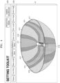
- FIG. 4 illustrates an example of a 3D projection plane and a projection plane editing screen, according to an embodiment of the present disclosure.
- FIG. 4 illustrates an example of a user interface providing a projection plane screen 41, a setting menu 420, and a projection plane editing menu 430, according to an embodiment of the present disclosure.
- the projection plane screen 410 displays a 3D projection plane on which images obtained by SVM cameras installed on a ship may be projected.
- An existing SVM image for a vehicle is generated by projecting and matching a plurality of captured images onto a hemispherical projection plane, based on a homography value calculated through pattern photographing.
- a vehicle has a small aspect ratio, and thus, it is possible to generate an SVM image that covers almost all angles around the vehicle with only four front, back, left, and right cameras, and even if a hemispherical projection plane is applied, distortion of a photographed object may be low.
- a ship has a large aspect ratio compared to a vehicle, and considering a coverage area of a camera, one or more SVM cameras need be installed on a side of the ship. Thus, when projecting a camera image on a hemispherical projection plane such as the ship, distortion of a photographed object may occur.
- the processor 130 may generate a 3D SVM image by projecting a plurality of obtained camera images onto an irregular 3D projection plane, based on conversion relationships between a plurality of cameras.
- the 3D projection plane generated around the ship S may have a hemispherical form with a semicylindrical insert.
- an embodiment is not limited thereto, and an elliptical hemisphere capable of effectively displaying a surrounding area of the ship may be the 3D projection plane of the present disclosure.
- the processor of the present disclosure can calculate the conversion relationship between the virtual camera and the actual camera image, so it determines the projection plane of the combined shape of a semicylinder and a hemisphere, and places and matches the actual camera images on the projection plane to create a 3D image.
- SVM images can be generated.
- a shape of the 3D projection plane may be determined based on a shape of the ship or installation information of the plurality of cameras.
- the shape of the ship or the installation information of the plurality of cameras may be obtained from the own ship DB 140 or obtained according to a user input value.
- an existing method of generating an SVM image through pattern photographing only identifies a relationship between adjacent cameras, and thus, it is not possible to freely set a projection plane, and arrange and match images on the projection plane, as in an embodiment of the present disclosure.
- the 3D projection plane may be a 3D projection plane generated to project images generated by eight cameras installed on the ship S.
- the 3D projection plane may include first to eighth areas 411 to 418, and the areas may respectively correspond to the eight cameras installed on the ship S.
- the first area 411 may be an area where an image obtained from a bow camera of the ship is projected
- the second and third areas 412 and 413 may be areas where images obtained from blind-view cameras installed to photograph blind sectors on left and right sides of the bow of the ship are projected
- the eighth area 418 may be an area where an image obtained from a stern-side camera of the ship is projected.
- the projection plane on which the SVM image according to an embodiment of the present disclosure is projected may be set to include the horizon.
- an existing SVM image it is impossible to generate an SVM image including the horizon when a camera is installed to face perpendicularly downward.
- by setting installation postures such that actual cameras face the floor obliquely rather than perpendicularly it is possible to generate a 3D projection plane in the form of hemisphere or elliptical hemisphere and include a horizontal plane to an image projected on the generated 3D projection plane.
- an angle of the actual camera being installed may be freely selected.
- a camera installation posture may be 45 degrees considering a region of interest (ROI).
- an overlapping area between areas in the 3D projection plane.
- the overlapping area indicates an area where some photographing areas overlap each other depending on a coverage range of an installed camera, and for example, an overlapping area 419 may be present between the first area 411 and the third area 413.
- An image naturally stitched through calibration between cameras according to deriving of a conversion relationship described above may be displayed in the overlapping area, and when images are misaligned due to internal or external factor of the ship, a calibration setting may be changed through a user input.
- the setting menu 420 and the projection plane editing menu 430 may be additionally displayed.
- the setting menu 420 may include a menu for changing a projection plane view setting (PROJECTION MODEL) and a calibration setting menu (CAMERA CALIBRATION).
- the projection plane editing menu 430 may provide, as menus, items for editing a 3D projection plane displayed on the projection plane screen 410.
- the processor 130 may generate an SVM image by projecting camera images onto an irregular 3D projection plane, and at this time, settings of a shape and inclination of the irregular 3D projection plane may be adjusted by a user input.
- a user may adjust a curvature or radius of a projection plane through a Radius item of the projection plane editing menu, remove a portion of the projection plane by adjusting a ratio of cropping an image through a Crop Ratio item, set a base length of the ship through a Base Length item, adjust a side ratio in front of the ship through a Side Ratio (Bow) item, adjust a side ratio at the rear of the ship through a Side Ratio (Stern) item, adjust a length of sides of the ship through a Side Center item, adjust a side length of the ship through a Side Length item, emphasize or reduce an upper portion of the ship by adjusting an inclination of the projection plane through an Over Angle item, and emphasize or reduce a lower portion of the ship by adjusting an inclination of the projection plane through an Under Angle item.
- a Radius item of the projection plane editing menu remove a portion of the projection plane by adjusting a ratio of cropping an image through a Crop Ratio item, set
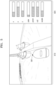
- FIG. 5 illustrates an example of a user interface for displaying and adjusting an SVM image, according to an embodiment of the present disclosure.
- the processor 130 may generate 2D and 3D SVM images in real time.
- a transformation matrix homoography matrix
- the present disclosure may calibrate a plurality of cameras by using a concept of a virtual camera and generate an SVM image.
- a conversion relationship between images of a virtual camera and an actual camera may be calculated by applying a concept of the virtual camera, and thus, even if an installation location or installation posture of a camera is changed, only a new SVM image may be generated in real time as long as changed location and posture information is present.
- the generated SVM image is a top-view SVM image in which the virtual camera located at the top of a ship looks down on the ship and surroundings.
- an entire area of an SVM image projected on a 3D projection plane, as shown in FIG. 3 may be displayed as the SVM image of the virtual camera.
- it is possible to adjust, in real time, an area and principal point in the SVM image, which are shown to a user, and thus, a user interface as if a location and posture of a camera are adjusted in real time may be provided.
- the user interface of FIG. 5 for displaying and adjusting an SVM image may include an image display area 510 and an adjustment area 520.
- an interface for selecting an SVM camera desired to be adjusted may be additionally provided.
- the embodiment of FIG. 5 is an example in which a selected SVM camera is a bow camera 501 and an SVM image is displayed based on the bow camera 501.
- the SVM image displayed in the image display area 510 may be an SVM image that uses a specific point of an image captured by the bow camera 501 as a principal point.
- a partial area, rather than the entire area, of the SVM image projected on the 3D projection plane may be displayed as the SVM image of the virtual camera.
- the principal point and scale of the displayed SVM image may be changed by controlling an installation posture and scale of the virtual camera.
- a partial area of the 3D projection plane with a specific point in an area captured by a specific camera (bow camera) as the principal point is displayed in the image display area 510 as the SVM image of the virtual camera.
- a camera may be installed to face an area of most interest when the ship sails.
- actual cameras may be installed such that principal points of cameras face points of most interest during sailing, for example, a camera installed on the bow may be installed to face an angle inclined 45 degrees downward from the horizon.
- a camera is unable to be installed to face a point desired by the user depending on a type of the ship, or where the user wants to change a principal point of an already installed camera at his/her discretion.
- a user interface that has a same effect as adjusting a posture and scale of an actual camera may be provided.
- the user may adjust the SVM image by adjusting each parameter (x, y, z, yaw, pitch, roll, or scale) item in the image adjustment area 520.
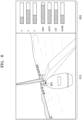
- FIG. 6 illustrates an example of an SVM image adjusted by a user, according to an embodiment of the present disclosure.
- an SVM display area 610 in FIG. 6 displays an SVM image when a user adjusts yaw and scale values.
- an image adjustment area 620 of FIG. 6 like FIG. 5 , the user may input x, y, z, yaw, pitch, roll, and scale values.
- An installation posture and scale of a virtual camera may be changed according to a user input in the image adjustment area 620.
- an SVM image rotated by about 30 degrees in a yaw direction and having a larger scale compared to FIG. 5 may be provided in the image display area 610 ( SVM ).
- an image provided in the image display area 610 may be an image in which a roll value and a pitch value of a bow camera 601 are changed.
- a scale and a principal point viewed by the virtual camera are changed with respect to an SVM image, in which images obtained by calibrating a plurality of cameras are projected on a 3D projection plane, and thus, a same effect as changing the installation posture and scale of the actual camera may be obtained.
- the image adjustment areas 520 and 560 of FIGS. 5 and 6 may be provided for direct camera calibration by an operator or user.
- the operator or user may directly perform calibration by selecting the calibration setting menu (CAMERA CALIBRATION).
- the processor 130 of the present disclosure may generate an SVM image by automatically calibrating cameras using only installation information of actual cameras by using a concept of a virtual camera.
- a user interface for changing pre-stored calibration settings is required.
- a user interface for adjusting pre-stored conversion relationships between the virtual camera and the actual cameras may be additionally provided.
- the user interface for adjusting the calibration settings may be similar to the image display and adjustment interface of FIG. 5 or 6 .
- an error or misalignment in calibration may be mainly found in an overlapping area between camera images.
- images are not stitched correctly in the overlapping area 419 between the first area 411 and the third area 413 in FIG. 4 and are misaligned.
- the user may correct the misaligned calibration settings by directly adjusting location, yaw, pitch, roll, and scale settings of the image through the image adjustment interface.
- the user or operator may view an SVM image in an interface environment such as FIG. 5 or 6 and adjust camera calibration misalignment, and the pre-stored conversion relationships between the virtual camera and the actual cameras may be reset by an input of the user or operator.
- FIG. 7 is a diagram showing an example of a camera being installed on a ship, according to an embodiment of the present disclosure
- FIG. 8 is a diagram showing an example of the ship of FIG. 7 viewed from the side.
- FIGS. 7 and 8 illustrate a ship 1 shown in FIGS. 7 and 8
- a ship 1 shown in FIGS. 7 and 8 is a leisure boat
- embodiments of the present disclosure are not necessarily limited thereto and any form, size, and type of ships may be applied.
- FIG. 7 illustrates a top view of a leisure boat, on which cameras 111a to 111d are installed, viewed from the top
- the FIG. 8 illustrates a side view of a leisure boat viewed from the side.
- installation locations of the cameras 111a, 111b, 111c, and 111d may include at least the top of a cabin of the leisure boat, a bow of the leisure boat, a stern of the leisure boat, and a center portion of a line connecting the top of the cabin and the bow by projecting the top of the cabin and the bow on a surface of the sea.
- the camera 111a may be installed at a bow installation location. At this time, the camera 111a may be installed at an edge corner of the bow, and may be installed such that other obstacles are not captured in an image of the camera 111a.
- the camera 111a installed on the bow may be installed at an angle in a range of 0 to 90 degrees in a direction of the water, preferably at 45 degrees, so as to capture the horizon.
- the camera 111d may be installed at a stern-side installation location of the leisure boat. At this time, the camera 111d may be installed at a location corresponding to a high point of the stern and may be installed such that no obstacles are located below the installation posture of the camera 111d. Like the camera 111a installed at the bow, the camera 111d installed at the stern may be installed at an angle in a range of 0 to 90 degrees, preferably at 45 degrees, so as to capture the horizon.
- the camera may be installed at a side location 111c of the leisure boat.
- the required number of cameras 111c installed at the side locations may be determined according to installation heights of the cameras and a camera angle of view.
- a coverage area of the camera 111c installed at the side location may be set to 4.5 times the camera installation height, and the installation location may be determined such that the coverage areas of the cameras 111c minimize a blind sector.
- the camera 111c installed on the side may be installed at an angle in a range of 0 to 90 degrees in the direction of the water, preferably at 45 degrees.
- the blind-view camera 111b capable of photographing a blind sector of the leisure boat may each be installed on the left and right sides below a curve of the bow.
- Ships have long bows, and thus blind sectors are easily formed at the bows.
- unlike vehicles that have brakes and thus can stop quickly ships do not have brakes.
- blind spots are also large, and in particular, collisions in blind spots may occur frequently due to characteristics of ships, which have spindle shapes at the bottoms. Accordingly, in a case of a ship having a spindle-shaped or bell-shaped bottom portion, when a camera is installed only on a deck of the ship, a blind sector may occur and there is a high possibility that a collision accident will occur in the blind sector.
- the camera 111b may be installed below the curve of the blind sector to photograph the blind sector. Meanwhile, the camera 111b installed below the curve, according to an embodiment, does not need to face the horizon (because the camera installed at the bow described above is already photographing the horizon), and may be installed to perpendicularly face the water surface.
- the blind-view camera 111b may be installed in a center portion of a line 112 connecting the top of the cabin and the bow by projecting the same on the surface of the sea. Accordingly, the top of the cabin and the bow may be perpendicularly connected to the horizontal plane by using drawing information stored in the own ship DB 140, the straight line 112 connecting points in contact with the horizontal plane may be set, and both ends of the line 112 may be connected to the top of cabin, thereby forming a triangle, and the center of the line 112 may be perpendicularly connected to install the camera 111b at a portion in contact with a hypotenuse of the triangle.
- installation heights of cameras installed on the ship may be different as shown in FIG. 8
- an SVM image of the leisure boat may be generated by calibrating the cameras with different installation heights.
- an SVM image is generated by using a virtual camera, and thus locations and heights of actual cameras may be freely set.
- a blind spot occurred during approaching/berthing may be minimized even for a ship with nay shape, and information about surrounding situation recognition may be provided.
- installation information of an image capturing unit 110 may be stored in the own ship DB 140.
- An installation location of the camera 111 may be obtained by using a drawing of the ship input from the own ship DB 140, and an installation posture of the camera 111 may be obtained through a manual input of the user or from the own ship DB 140 stored through an input of the user.
- the installation posture of the camera 111 may be obtained by extracting a horizontal plane from an image obtained by the image capturing unit 110 and calculating an angle of the camera 111 with respect to the horizontal plane.
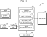
- FIG. 9 illustrates a ship including an apparatus for generating an SVM image, according to another embodiment of the present disclosure.
- FIG. 9 is a modified example of FIG. 1 , and redundant description will be omitted.
- a ship monitoring device or an apparatus 100 for generating an SVM image may include the image capturing unit 110 including the plurality of cameras 111 installed on a ship and photographing a surrounding area of the ship, the LiDAR sensor 120 obtaining one or more point clouds through a signal reflected by being transmitted to the surrounding area of the ship, and the processor 130 generating an SVM image by projecting, in a viewpoint of a virtual camera located at the top of the ship, an image of the image capturing unit 110 on an irregular 3D projection plane about the surrounding area of the ship, which is set by using installation information of the image capturing unit 110 and LiDAR data obtained by the LiDAR sensor 120.
- Blocks of FIGS. 1 and 9 are divided conceptually to facilitate the description of the present disclosure, and interpretation of embodiments of the present disclosure is not limited to the division of the blocks.
- the processor 130 may include, in addition to the camera calibration unit 131 described above, the image fusion unit 132 projecting an image on the pre-set 3D projection plane of the surrounding area of the ship, according to distance information obtained by the LiDAR sensor 120 and the installation information of the image capturing unit 110.
- the processor 130 may include an image reconstruction unit 134 deforming a 3D projection plane corresponding to a point of the image, where an object is identified, by using information about the length of the object, obtained by the LiDAR sensor 120, and stitching the image.
- the processor 130 may further include an occupancy grid map generation unit 133 generating an occupancy grid map obtained by displaying, on a 3D projection plane split into a plurality of lattices, a lattice with a detected object as an occupancy grid by using the LiDAR data.
- the ship 1 may be a ship of any shape and may particularly include a small ship such as a leisure boat.
- installation information includes an installation location or installation posture of the camera 111 in the ship 1, wherein the installation location is a relative coordinate location of each camera 111 with a center of the ship 1 as the origin and the installation posture may include an angle at which the camera 111 is mounted or a direction in which the camera 111 faces.
- image stitching may be performed without having to perform a separate camera matching process before and after installation of the cameras 111a, 111b, 111c, and 111d, by using the installation information of the image capturing unit 110 and the LiDAR data obtained by the LiDAR sensor 120.
- the LiDAR sensor 120 may be arranged at the center of the ship 1 or at the top of the cabin.
- the image fusion unit 132 may project the image on the pre-set 3D projection plane of the surrounding area of the ship according to the distance information obtained by the LiDAR sensor 120 and the installation information of the image capturing unit 110, and the image reconstruction unit 134 may deform the 3D projection plane corresponding to the point of the image, where the object is identified, by using the information about the length of the object, obtained by the LiDAR sensor 120. Image distortion may be prevented through intentional deformation and image stitching.
- a reason distortion occurs in an SVM image of the prior art is because a camera image uses a 3D projection plane with a pre-set regular shape, and for example, a hemispherical projection plane where the ship 1 is located at a point of contact with the floor is used.
- a projection plane of a regular shape is used without considering the object, the object with the long length is projected on an SVM image in an unrealistically large size.
- the irregular 3D projection plane of the surrounding area of the ship may be intentionally deformed by using distance information between the ship 1 and an underwater object 2, obtained by the LiDAR sensor 120, or length information of the underwater object 2.
- the distance information between the ship 1 and the underwater object 2, obtained by the LiDAR sensor 120 is mapped with an image of the underwater object 2, captured by the image capturing unit 110, and the image is projected on the 3D projection plane according to the distance information, i.e., when the 3D projection plane is deformed according to the distance information and the image is projected on the deformed 3D projection plane, a 3D SVM image without distortion may be obtained.
- the image in which the underwater object 2 is photographed may be projected on the 3D projection plane, and a portion of the 3D projection plane, on which the image including the underwater object 2 is projected, may be deformed according to the length of the underwater object 2, considering presence of the underwater object 2 and the length of the underwater object 2, obtained by the LiDAR sensor 120, thereby preventing distortion of the 3D SVM image caused by the presence of the underwater object 2.
- the image fusion unit 132 may three-dimensionally convert a 2D image according to the LiDAR data by applying calibration between the LiDAR sensor 120 and the image capturing unit 110, and fuse the image with the LiDAR data.
- Data may be fused by matching a plane on which an image is projected with a virtual plane generated from 3D coordinates of LiDAR data.
- the occupancy grid map generation unit 133 may divide the fused data into a plurality of lattices and display an area where the underwater object 2 is present as an occupancy grid.
- the image reconstruction unit 134 may deform a 3D projection plane corresponding to the lattice indicated by the occupancy grid and stitch an image projected on the 3D projection plane of an irregular shape.
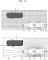
- FIG. 10 illustrates a portion of a 3D projection plane before deformation is reflected and a LiDAR sensor range 122 where the LiDAR sensor 120 detects the underwater object 2, and as shown in FIG. 9 , when an image is projected on the 3D projection plane based on the ship 1, the underwater object 2 located in the surrounding area of the ship may also be projected.
- an area where the underwater object 2 is estimated to be present as shown in an upper diagram of FIG. 10 may be displayed as an occupancy grid, and deformation may be applied to a corresponding 3D projection plane.
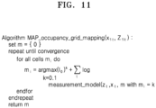
- the occupancy grid map generation unit 133 may generate an occupancy grid map by using a maximum a posteriori estimation algorithm.
- occupancy grid map information robust against noise caused by relatively slow-moving ship movement and waves, ripples, and the like may be configured, an occupancy grid may be estimated from an occupancy grid map, and a 3D projection plane corresponding to the estimated occupancy grid may be deformed.
- an optimization calculation for applying an occupancy grid map in real time may be performed by using LiDAR data obtained in real time from the LiDAR sensor 120 by performing a maximum a posteriori estimation algorithm.
- the processor 130 may further include a filtering unit 121 performing filtering on data obtained by the LiDAR sensor 120 by applying a intensity filter.
- a resolution may be too high, resulting in a waste of resources or memory of a computing device. Accordingly, for processing the large amount of LiDAR data, granularity may be changed such that only bearing angle actually applied on a ship may be processed.
- the resolution may be reduced by increasing density of the LiDAR data, which secures a 360-degree point cloud about a surrounding area of the ship, from 1 degree to 2 degrees.
- the ship 1 detects the underwater object 2 in an outdoor environment where there is sunlight or reflected light reflected from an object, and thus, in order to stably obtain LiDAR data in a strong lighting environment in the outdoor environment, the intensity filter may be applied. By filtering out information about areas with high distortion, data throughput may be reduced and stability may be improved.
- a 3D SVM image may be quickly obtained through the above-described processes without a separate matching process, and the 3D SVM image may be displayed on a display unit 150.
- the display unit 150 may be a multi-function display (MFD) device previously installed on the ship 1.
- MFD multi-function display
- the 3D SVM image may be transmitted not only to the MFD device of the ship 1 but also to a separate mobile device, thereby promoting user convenience.
- the image capturing unit 110 may decompress an image obtained by the camera 111 and then perform image pre-processing to perform data fusion, stitching, and the like.
- image pre-processing to perform data fusion, stitching, and the like.
- image stitching may be performed without separate camera matching even on a ship that is unable to pre-photograph a pattern that may serve as a standard as in a vehicle, and as shown in FIG. 3 , a 3D SVM image may be obtained even while horizontal levels of a bow and a stern continuously change during sailing. Intuitive information about surroundings of the ship may be provided to a powerboat driver, and thus convenience and safety of the driver may be increased.
- a ship 3D monitoring method may include photographing a surrounding area of a leisure boat by using the image capturing unit 110 (shown in FIG.9 ) installed on the leisure boat (operation S610), obtaining one or more point clouds through a signal reflected by being transmitted to the surrounding area of the leisure boat by using the LiDAR sensor 120 (shown in FIG. 12 ).
- Operations S630 and S640 may include projecting the image on a pre-set 3D projection plane of the surrounding area of the ship, according to distance information obtained by the LiDAR sensor 120 and the installation information of the image capturing unit 110, and deforming a 3D projection plane corresponding to a point of the image, where an object is identified, by using information about a length of the object, obtained by the LiDAR sensor 120, and stitching the image.
- the ship 3D monitoring method may further include generating an occupancy grid map obtained by displaying, on the 3D projection plane split into a plurality of lattices, a lattice with a detected object as an occupancy grid by using the LiDAR data.
- the lattice displayed as the occupancy grid may be deformed and the image may be stitched.
- the generating of the occupancy grid map may include generating the occupancy grid map by using a maximum a posteriori estimation algorithm. Details that overlap those described above are omitted.
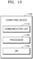
- FIG. 13 illustrates a computing device according to an embodiment.
- a server 1100 of FIG. 13 may include a communication unit 1110, a processor 1120, and a DB 1130.
- the processor 1120 may physically or conceptually include the processor 130 of FIG. 1 or the processor 130 of FIG. 9
- the DB 1130 may include the own ship DB 140. Only components related to an embodiment are shown in the computing device 1100 of FIG. 12 . Accordingly, it would be obvious to one of ordinary skill in the art that the server 1100 may further include general-purpose components other than the components shown in FIG. 12 .
- the communication unit 1110 may include one or more components enabling wired/wireless communication with other nodes.
- the communication unit 1110 may include a short-range wireless communication unit (not shown), a mobile communication unit (not shown), and a broadcast receiving unit (not shown).
- the DB 1130 is hardware storing various types of data processed in the computing device 1100, and may store a program for processes and control by the processor 1120.
- the DB 1130 may store ship information, camera installation information, and the like.
- the DB 1130 may include random access memory (RAM) such as dynamic random access memory (DRAM) or static random access memory (SRAM), read-only memory (ROM), electrically erasable programmable read-only memory (EEPROM), CD-ROM, Blu-ray or another optical disk storage, hard disk drive (HDD), solid state drive (SSD), or flash memory.
- RAM random access memory
- DRAM dynamic random access memory
- SRAM static random access memory
- ROM read-only memory
- EEPROM electrically erasable programmable read-only memory
- CD-ROM compact disc-read-only memory
- Blu-ray or another optical disk storage hard disk drive (HDD), solid state drive (SSD), or flash memory.
- the processor 1120 controls overall operations of the computing device 1100.
- the processor 1120 may execute programs stored in the DB 1130 to control an input unit (not shown), a display (not shown), the communication unit 1110, and the DB 1130, in general.
- the processor 1120 may execute the programs stored in the DB 1130 to control operations of the computing device 1100.
- the processor 1120 may be realized by using at least one of an application-specific integrated circuit (ASIC), a digital signal processor (DSP), a digital signal processing device (DSPD), a programmable logic device (PLD), a field programmable gate array (FPGA), a controller, a micro-controller, a microprocessor, and electric units for performing other functions.
- ASIC application-specific integrated circuit
- DSP digital signal processor
- DSPD digital signal processing device
- PLD programmable logic device
- FPGA field programmable gate array
- controller a micro-controller
- microprocessor a microprocessor
- the embodiments according to the present disclosure may be implemented in a form of a computer program executable by various components on a computer, and such a computer program may be recorded in a computer-readable medium.
- the computer-readable medium may include hardware devices specially designed to store and execute program instructions, such as magnetic media, such as a hard disk, a floppy disk, and a magnetic tape, optical recording media, such as CD-ROM and DVD, magnetooptical media such as a floptical disk, and read-only memory (ROM), random-access memory (RAM), and a flash memory.
- the computer program may be specially designed for the present disclosure or well known to one of ordinary skill in the computer software field.
- Examples of the computer program include not only machine codes generated by a compiler, but also high-level language codes executable by a computer by using an interpreter or the like.
- a method may be provided by being included in a computer program product.
- the computer program products are products that can be traded between sellers and buyers.
- the computer program product may be distributed in a form of machine-readable storage medium (for example, a compact disc read-only memory (CD-ROM)), or distributed through an application store (for example, Play Store TM ) or directly or online between two user devices (for example, download or upload).
- an application store for example, Play Store TM
- online distribution at least a part of the computer program product may be at least temporarily stored or temporarily generated in the machine-readable storage medium such as a server of a manufacturer, a server of an application store, or a memory of a relay server.
Landscapes
- Engineering & Computer Science (AREA)
- Multimedia (AREA)
- Signal Processing (AREA)
- Physics & Mathematics (AREA)
- Mechanical Engineering (AREA)
- General Physics & Mathematics (AREA)
- Ocean & Marine Engineering (AREA)
- Combustion & Propulsion (AREA)
- Chemical & Material Sciences (AREA)
- Theoretical Computer Science (AREA)
- Remote Sensing (AREA)
- Radar, Positioning & Navigation (AREA)
- Health & Medical Sciences (AREA)
- Public Health (AREA)
- Electromagnetism (AREA)
- Computer Networks & Wireless Communication (AREA)
- Human Computer Interaction (AREA)
- Closed-Circuit Television Systems (AREA)
- Image Processing (AREA)
- Studio Devices (AREA)
Abstract
Description
- Embodiments relate to a method and apparatus for generating a surround view monitoring (SVM) image for a ship. More particularly, embodiments relate to a method and apparatus for calibrating a plurality of cameras by using a virtual camera concept without pattern photographing, and generating an SVM image.
- In addition, embodiments relate to a 3-dimensional (3D) monitoring apparatus and method for a leisure boat, and more particularly, to an apparatus and method capable of obtaining a distortion-free 3D SVM screen without a separate matching process by deforming an image by using camera installation information and a light detection and ranging (LiDAR) sensor.
- Recently, monitoring systems using around view monitoring (AVM) and surround view monitoring (SVM) screens have been introduced to vehicles. This is a technology that installs cameras on front, rear, left, and right sides of a vehicle to photograph the front, rear, left, and right sides of the vehicle, and then combines such camera images to provide a top view.
- In
prior Patent Document 1, pixels of a wide-angle image input from a camera are mapped to corresponding coordinates and images are combined based on valid pixels, thereby minimizing distortion such as image quality deterioration that occurs when the wide-angle image is converted into a narrow-angle image. Recently, attempts have been made to apply SVM images to ships so as to complement ship environments where continuous forward watching is not possible, but it is difficult to apply SVM systems of vehicles to the ships due to differences between ships and vehicles. - When viewed from the top, a ship has a curved hull as a whole, with the front becoming narrower toward the head, and its height above the water is not constant. Accordingly, compared to vehicles with a rectangular shape and a constant height from the ground, it is difficult to realize practical SVM screens for spindle-shaped ships because, even when images are obtained from cameras attached to same locations as vehicles and surrounding images are matched, areas (bottom left and right of bows) with highest risks are mostly hidden as blind spots.
- In addition, ships do not have uniform shapes and there is a large height difference between installation locations of mounted cameras, but existing vehicle SVM is mostly installed at similar heights and similar locations (front, rear, below a left sideview mirror, and below a right sideview mirror), and thus camera installation locations according to ships are not considered. Moreover, unlike vehicles that have elements that serve as mapping standards, such as lanes or crosswalks, it is very difficult for ships to simply map pre-set pixels in an image to corresponding coordinates.
- Accordingly, it is difficult to apply a matching process for SVM image combination for vehicles to ships, and even if a camera matching process is performed before floating ships on the water, distortion is still very large when the SVM image combination is performed during sailing because, unlike vehicles traveling on a static horizontal road, ships are rigid bodies maintained above fluid by buoyancy, and thus, the centers of gravity and states of ships change before and after setting ships afloat, and bows is lifted depending on speeds of ships.
- In
Patent Document 2, in order to apply SVM of a vehicle to a ship, images are combined based on an overlapping reference point by using a boundary between the ship's hull and the water as a first reference line and a boundary between the water and the land as a second reference line. - However,
Patent Document 2 does not consider camera locations according to differences in shapes between vehicles and ships, and when there is an underwater object, such as a pole or a crane, between the boundaries, it is difficult to control the underwater object to be captured in an SVM image without distortion. - (Patent Document 1)
KR 10-2441052 B1 - (Patent Document 2)
KR 10-2052013 B1 - A purpose of the present disclosure is to generate a real-time 2-dimensional (2D) or 3-dimensional (3D) surround view monitoring (SVM) image by matching and calibrating images obtained from a plurality of cameras with high accuracy without pattern photographing, by using a concept of virtual camera.
- Also, another purpose of the present disclosure is to provide a 3D monitoring apparatus and method for a leisure boat, which may obtain an SVM image without distortion caused by an underwater object by using a 3D projection plane having an irregular shape, which is deformed by using a light detection and ranging (LiDAR) sensor and a camera installation location suitable for a ship.
- Aspects of the present disclosure are not limited to those mentioned above, and other aspects and advantages of the present disclosure, which are not mentioned, will be understood from descriptions below and will become more apparent by embodiments of the present disclosure. In addition, the aspects and advantages of the present disclosure will be realized through means and combinations thereof in the claims.
- According to an embodiment of the present disclosure, provided is a method of generating a surround view monitoring (SVM) image, including: obtaining installation information of an actual camera installed on a ship; setting a virtual camera; calculating a conversion relationship between the virtual camera and the actual camera, based on the installation information of the actual camera; and generating an SVM image based on the calculated conversion relationship.
- In the present disclosure, the setting of the virtual camera may include setting the virtual camera to perpendicularly face a ground plane of a world coordinate system.
- In the present disclosure, the generating of the SVM image may include: determining a 3-dimensional (3D) projection plane, based on a shape of the ship or the installation information of the actual camera; and generating a 3D SVM image by projecting an image obtained from the actual camera on the 3D projection plane.
- In the present disclosure, the 3D projection plane may have an elliptical hemisphere or hemispherical form with a semicylindrical insert at a center thereof.
- In the present disclosure, the 3D projection plane may be an irregular projection plane in which at least one item from among a radius of a projection plane, a front-back length of a ship, a side length of a ship, a side ratio of a ship, and an inclination of a projection plane is adjustable a user input.
- In the present disclosure, the actual camera may have an installation posture inclined at 0 to 90 degrees, based on a direction perpendicular to a ground plane of a world coordinate system, and the generated SVM image may display the sea horizon in at least a portion thereof.
- In the present disclosure, the actual camera may be a blind-view camera installed to photograph a blind sector located below a waist of a spindle-shaped ship, and the generating of the SVM image may include generating the SVM image, based on a conversion relationship between the blind-view camera and the virtual camera.
- In the present disclosure, the installation information of the actual camera may include an installation location, an installation height, and an installation posture, and in the present disclosure, a plurality of the actual cameras may be provided on the ship, and two or more of the plurality of actual cameras may have different installation heights and different installation postures.
- In the present disclosure, the method may further include providing a user interface for displaying and adjusting the SVM image and the virtual camera, wherein the user interface may be an interface that allows adjustment of display settings of the SVM image, according to a user input.
- In the present disclosure, the display settings of the SVM image, which are adjustable according to the user input, may include a location and yaw, pitch, roll, and scale settings of the SVM image, and the SVM image may be changed in real time as the display settings are adjusted.
- In the present disclosure, the method may further include providing a calibration setting adjustment interface for adjusting the conversion relationship between the virtual camera and the actual camera, wherein the calibration setting adjustment interface may reset, according to a user input, a pre-stored conversion relationship between the virtual camera and the actual camera.
- In the present disclosure, the method may further include: obtaining one or more point clouds through a signal reflected by being transmitted to a surrounding area of the ship, by using a light detection and ranging (LiDAR) sensor; generating, in real time, a 3D projection plane having an irregular shape for the surrounding area of the ship set by using the installation information of the actual camera and depth information of an object obtained by the LiDAR sensor; and performing image fusion of projecting images of a plurality of cameras in a viewpoint of the virtual camera located on top of the ship.
- In the present disclosure, the method may further include dynamically updating the 3D projection plane based on artificial intelligence or the depth information of the object obtained by the LiDAR sensor.
- According to another embodiment of the present disclosure, provided is an apparatus for generating a surround view monitoring (SVM) image, including: a plurality of actual cameras provided on a ship and configured to photograph a surrounding area of the ship, wherein at least two actual cameras have different installation heights; and a processor configured to generate an SVM image from a plurality of images obtained from the plurality of actual cameras, by using a virtual camera that perpendicularly face a ground plane of a world coordinate system.
- According to the above-described technical solutions of the present disclosure, a 3-dimensional (3D) surround view monitoring (SVM) image can be generated by calculating a conversion relationship between a virtual camera and actual cameras without pattern photographing.
- According to an embodiment of the present disclosure, installation heights of SVM cameras installed on a ship can be determined differently, and installation locations and heights can be changed even after the installation.
- According to an embodiment of the present disclosure, even when installation information of an actual camera is changed, an SVM image can be generated in real time without pattern photographing, and an operator or user can adjust a calibration setting value.
- According to an embodiment of the present disclosure, by intentionally deforming a 3D projection plane, on which a captured image is projected, by using light detection and ranging (LiDAR) data obtained through a LiDAR sensor, image distortion can be prevented in a coastal area where many underwater objects are detected, in particular, in a berthing area.
- According to an embodiment of the present disclosure, image matching can be performed by using camera installation location information without a separate camera matching process, and thus, camera installation for matching is facilitated.
- Purposes of the present disclosure are not limited to those mentioned above, and other purposes that are not mentioned will be clearly understood by one of ordinary skill in the art from the following description.
-
-
FIG. 1 is a block diagram of an apparatus for generating a surround view monitoring (SVM) image, according to an embodiment of the present disclosure. -
FIG. 2 is a flowchart of a method of generating an SVM image, according to an embodiment of the present disclosure. -
FIG. 3 is a diagram for describing a method of calculating a conversion relationship between a virtual camera and an actual camera, according to an embodiment of the present disclosure. -
FIG. 4 illustrates an example of a 3-dimensional (3D) projection plane and a projection plane editing screen, according to an embodiment of the present disclosure. -
FIG. 5 illustrates an example of a user interface for displaying and adjusting an SVM image, according to an embodiment of the present disclosure. -
FIG. 6 illustrates an example of an SVM image adjusted by a user, according to an embodiment of the present disclosure. -
FIG. 7 is a diagram showing an example of a camera being installed on a ship, according to an embodiment of the present disclosure, andFIG. 8 is a diagram showing an example of the ship ofFIG. 7 viewed from the side. -
FIG. 9 is a block diagram of an apparatus for generating an SVM image, according to another embodiment of the present disclosure. -
FIG. 10 is a conceptual diagram showing an occupancy grid map and a sensing range of a light detection and ranging (LiDAR) sensor, according to an embodiment of the present disclosure. -
FIG. 11 is a diagram showing a maximum posterior probability estimation algorithm according to an embodiment of the present disclosure. -
FIG. 12 is a flowchart of a 3D monitoring method for a ship, according to an embodiment of the present disclosure. -
FIG. 13 illustrates a computing device according to an embodiment of the present disclosure. - Advantages and features of the present disclosure and methods of accomplishing the same may be understood more readily by reference to the following detailed description of the embodiments and the accompanying drawings. However, it should be understood that the present disclosure is not limited to the embodiments presented below, but may be implemented in various different forms, and include all transformations, equivalents, and substitutes included in the spirit and scope of the present disclosure.
- Also, the terms used in the present specification are only used to describe specific embodiments, and are not intended to limit the present disclosure. An expression used in the singular encompasses the expression in the plural, unless it has a clearly different meaning in the context. In the present specification, it is to be understood that terms such as "including" or "having", etc., are intended to indicate the existence of the features, numbers, steps, actions, components, parts, or combinations thereof disclosed in the specification, and are not intended to preclude the possibility that one or more other features, numbers, steps, actions, components, parts, or combinations thereof may exist or may be added.
- Some embodiments of the present disclosure may be represented by functional block configurations and various processing operations. Some or all of these functional blocks may be implemented by various numbers of hardware and/or software configurations that perform particular functions. For example, the functional blocks of the present disclosure may be implemented by one or more microprocessors or by circuit configurations for a certain function. Also, for example, the functional blocks of the present disclosure may be implemented in various programming or scripting languages. The functional blocks may be implemented by algorithms executed in one or more processors. In addition, the present disclosure may employ general techniques for electronic environment setting, signal processing, and/or data processing. Terms such as "mechanism", "element", "means", and "configuration" may be used widely and are not limited as mechanical and physical configurations.
- In addition, a connection line or a connection member between components shown in drawings is merely a functional connection and/or a physical or circuit connection. In an actual device, connections between components may be represented by various functional connections, physical connections, or circuit connections that are replaceable or added.
- In addition, various changes may be made to some embodiments of the present disclosure, and thus, specific embodiments will be illustrated in drawings and described in detail in the detailed description. Effects and features of the embodiments and methods of achieving the same will become apparent with reference to details described in detail with reference to the drawings. However, the embodiments are not limited to those described below, and may be implemented in various forms.
- In the following embodiments, the terms "first" and "second" are not used in a limited sense and are used to distinguish one component from another component. In the following embodiments, an expression used in the singular encompasses the expression of the plural, unless it has a clearly different meaning in the context. In the following embodiments, it will be further understood that the terms "comprise" and/or "comprising" used herein specify the presence of stated features or components, but do not preclude the presence or addition of one or more other features or components. In the following embodiments, when a part is "connected" to another part, the part may not only be "directly connected" to the other part, but may also be "electrically connected" to the other part with another element in between.
- Hereinafter, embodiments will be described in detail with reference to the accompanying drawings, and in the following description with reference to the drawings, like reference numerals refer to like elements and redundant descriptions thereof will be omitted.
-
FIG. 1 is a block diagram of an apparatus for generating a surround view monitoring (SVM) image, according to an embodiment of the present disclosure. - As shown in
FIG. 1 , aship monitoring device 1000 according to an embodiment of the present disclosure may include asensor 1200, aprocessor 130, and an input/output device 1400. - First, the
sensor 1200 is one or more sensors installed on a ship and may include one or more sensors from among a camera, radio detection and ranging (RADAR), light detection and ranging (LiDAR), a global positioning system (GPS), an automatic identification system (AIS), sound navigation ranging (SONAR), and an inertial measurement unit (IMU), but is not limited to the examples above. - According to an embodiment of the present disclosure, the
processor 130 may obtain installation information of an actual camera provided on the ship, set a virtual camera, calculate a conversion relationship between the virtual camera and the actual camera, based on the installation information of the actual camera, and generate an SVM image based on the calculated conversion relationship. According to another embodiment, theprocessor 130 may generate the SVM image according to an embodiment of the present disclosure, generate an image by fusing information from a plurality of sensors, generate an occupancy grid map, and reconstruct an image. In this regard, theprocessor 130 may include acamera calibration unit 131. Detailed operations of theprocessor 130 will be described below. - The input/
output device 1400 may include an input device that obtains a user input from the ship and an output device that outputs information to be provided to a user. For example, the input device may include a rudder controller, a steering wheel, a pedal, a joystick, a steering button, or a computing device including a touch screen interface, and the output device may include a visual output device such as a monitor or a head-up display, or an auditory output device such as a speaker, but examples thereof are not limited thereto. -
FIG. 2 is a flowchart of a method of generating an SVM image, according to an embodiment of the present disclosure. - Referring to
FIG. 2 , first, aprocessor 130 obtains installation information of actual cameras installed on a ship (operation 210). - Then, the
processor 130 sets a virtual camera perpendicularly facing a ground plane of a world coordinate system (operation 220). - Then, the
processor 130 calculates conversion relationships between the virtual camera and the actual cameras, based on the installation information of the actual cameras (operation 230). - Then, the
processor 130 generates an SVM image based on the calculated conversion relationships (operation 240). - In the following specification, in relation to the method of generating an SVM image, described in
FIG. 2 , an embodiment of generating the SVM image by performing calibration by using a concept of the virtual camera, reconstructing the generated SVM image by using a LiDAR sensor, and generating an occupancy grid map will be described in further detail. - First, the
camera calibration unit 131 may calculate the conversion relationship between actual cameras and the set virtual camera, and generate the SVM image by calibrating the virtual camera and the actual cameras, based on the calculated conversion relationship. Unlike thecamera calibration unit 131, animage fusion unit 132 described below may perform image fusion of generating a single 3-dimensional (3D) SVM image by combining and integrating pieces of image information obtained from several sources (according to an embodiment of the present disclosure, acamera 111 and a LiDAR sensor 120). - In detail, the
camera calibration unit 131 according to an embodiment of the present disclosure may generate the SVM image for monitoring a surrounding area of the ship. Here, the SVM image is obtained by generating one top-view image by combining a plurality of images obtained from a plurality of cameras. - In this regard, there is an existing method of generating an SVM image of a vehicle. For example, to generate an SVM image of a vehicle, a specific pattern located around the vehicle is photographed, a homography matrix is calculated based on matching feature points, and images are matched based on the calculated homography matrix. At this time, the specific pattern is typically a chessboard pattern and may have at least four feature points.
- More specifically, a vehicle SVM image may be generated by installing a plurality of cameras and then performing a matching process through pattern photographing. The pattern photographing may be performed at an end-of-line of vehicle production. At the end-of-line of vehicle production, after assembling a vehicle and installing a camera, an operator may move the vehicle over a set pattern, fix a vehicle body, and use the camera to photograph the pattern placed around the vehicle. Also, an SVM image may be generated by recognizing patterns between obtained camera images, extracting feature points, estimating a correlation value (homography matrix value) between the camera images, and performing matching between the images, based on the estimated correlation value. At this time, the correlation value between the camera images may be derived between adjacent cameras (cameras capable of photographing a same pattern). Also, the operator may fine-tune the SVM image through a screen on a diagnostic device.
- In the above description, the homography matrix value, which refers to the correlation value between the camera images, is a value that defines a relationship between planar objects projected on the camera, and is used to match images from individual cameras and convert the same into a single SVM top-view image. In other words, when a pattern on a certain plane is photographed at a specific angle and the same pattern is photographed at another angle, a value for matching an object on these two planes may be referred to as the homography matrix value.
- In such an existing image matching method, the homography matrix value is estimated after recognizing the pattern because defining the homography matrix value is an essential procedure to generate one top-view image, i.e., the SVM image, as if a vehicle is photographed from the top, by matching the plurality of camera images. Also, in order to estimate the homography matrix value, at least a certain number of matching pairs is required, and thus, the pattern photographing is an essential procedure.
- However, in relation to the method of generating an SVM image of a ship, it is difficult to arrange a fixed pattern on the water around the ship, like a vehicle. In other words, the ship is unable to be located on a fixed floor like a vehicle, and it is difficult to arrange a specific pattern on the water in reality. In addition, even if camera calibration is performed at the time of ship building, when the ship is actually floated on the water, an angle formed by a camera with an actual water surface may change according to the ship's center of gravity, and thus, the camera calibration using a pattern may lead to inaccurate results.
- In this regard, existing technology uses a method of flying a drone above a ship to obtain actual top photographs, but spaces and costs are restricted.
- Accordingly, the
camera calibration unit 131 according to an embodiment of the present disclosure may calculate the conversion relationship between the virtual camera and the actual cameras, based on the installation location and posture information of the cameras installed on the ship, and generate the SVM image based on the calculated conversion relationship. In other words, according to an embodiment of the present disclosure, calibration between the virtual camera and the plurality of actual cameras is possible without pattern photographing of the virtual camera or drone photographing, and the SVM image may be generated based thereon. -
FIG. 3 is a diagram for describing a method of calculating a conversion relationship between a virtual camera and an actual camera, according to an embodiment of the present disclosure. - According to an embodiment of the present disclosure, first, the
processor 130 may calculate a conversion relationship between a virtual camera Cv and installed actual cameras Ck1, Ck2, and Ck3 by using a concept of the virtual camera Cv, in addition to the actual cameras Ck1, Ck2, and Ck3 installed on a ship. In other words, according to an embodiment of the present disclosure, calibration may be performed between the virtual camera Cv and the actual cameras Ck1, Ck2, and Ck3. - Referring to
FIG. 3 , theprocessor 130 may obtain installation information about the actual cameras Ck1, Ck2, and Ck3 and set the virtual camera Cv. In the embodiment ofFIG. 2 , only three actual cameras are illustrated, but according to another embodiment, it is obvious that the number of actual cameras may vary depending on a coverage range of a camera, and a shape and size of the ship. Hereinafter, a method of calculating the conversion relationship between the virtual camera Cv and the actual cameras Ck1, Ck2, and Ck3 will be described in more detail. - First, according to an embodiment of the present disclosure, the
processor 130 may obtain the installation information of the actual cameras Ck1, Ck2, and Ck3 installed on the ship. In detail, theprocessor 130 obtain, as the installation information, information about installation locations of the actual cameras Ck1, Ck2, and Ck3 in the ship, installation heights dk1, dk2, and dk3 thereof, and installation postures thereof for determining image planes Zk1, Zk2, and Zk3. Here, theprocessor 130 may obtain the installation information of the actual cameras Ck1, Ck2, and Ck3 from an own ship database (DB) 140 or according to a user input. The installation information of the actual cameras Ck1, Ck2, and Ck3 stored in theown ship DB 140 may be a value stored at the time of launching of the ship or initial installation of the actual cameras Ck1, Ck2, and Ck3, or may be a value pre-input by the user. - The
processor 130 may set the virtual camera Cv that has a set height dv and posture perpendicular to a ground plane (Z=0) of a world coordinate system. In other words, theprocessor 130 may set the posture of the virtual camera Cv such that the virtual camera Cv has an image plane Zv parallel to the ground plane of the world coordinate system. According to an embodiment of the present disclosure, the virtual camera Cv is a camera virtually set by theprocessor 130, unlike cameras that are actually installed, and thus, a location and posture thereof may be freely set. - According to an embodiment of the present disclosure, a generated 2D or 3D SVM image may be an image viewed from a viewpoint of the virtual camera Cv. Accordingly, it is possible to change a principal point and a display range of the SVM image viewed from the viewpoint of the virtual camera Cv by changing the set location and posture of the virtual camera Cv. In other words, the virtual camera Cv has a posture perpendicular to the ground plane when an initial conversion relationship is calculated, but after the conversion relationship is calculated, a height and posture may be freely changed to provide an SVM image that matches user settings.
- The
processor 130 may convert a plane imaged by the actual cameras Ck1, Ck2, and Ck3 such that Z=0 in the world coordinate system. In other words, the actual cameras Ck1, Ck2, and Ck3 have different installation postures, and thus, the individual image planes Zk1, Zk2, and Zk3 may also be different, and theprocessor 130 according to an embodiment of the present disclosure may convert the plane imaged by the actual cameras such that Z=0. In this case, any point (or pattern) photographed by each of the actual cameras Ck1, Ck2, and Ck3 may be a point that is present on Z=0. - The virtual camera Cv set by the
processor 130 faces the ground plane perpendicularly, and thus, any point (or pattern) present on the ground plane may be transmitted to the virtual camera Cv with only a changed scale. Meanwhile, as described above, theprocessor 130 pre-obtains the installation information of the actual cameras (installation locations, installation heights, and installation postures on the ship, in particular, a mounting location, a mounting angle, and a mounting height of a bracket), and thus, a distance between actual points (or patterns) may be calculated. Accordingly, theprocessor 130 may match points (or patterns) on a 2D or 3D ground plane photographed by the virtual camera, based on the calculated distance between the actual points (or patterns). Theprocessor 130 may calculate a conversion relationship between the virtual camera Cv and each of the actual cameras Ck1, Ck2, and Ck3, based on the matched points (or patterns). In the embodiment ofFIG. 2 , the conversion relationships between the virtual camera Cv and the actual cameras are calculated separately, and thus, three conversion relationships may be calculated. - In detail, a location, an angle, and a focal length of the virtual camera for generating an SVM image may be freely specified, and thus, the location, the angle, and the focal length of the virtual camera may be already known values. In addition, the focal length of the virtual camera is directly proportional to a screen magnification, and thus, a magnification conversion relationship and a posture conversion relationship between images of the actual camera and the virtual camera may be estimated based on the installation height and a camera installation posture value of the actual camera, without having to separately photograph a pattern or capture an image by using a drone or the like. In other words, the
processor 130 may generate an SVM image based on an installation angle and installation posture value of the actual camera, without pattern or drone photographing. - In a same manner as described above, according to an embodiment of the present disclosure, the conversion relationship between the virtual camera and the actual camera may be calculated by using the concept of the virtual camera even without the drone photographing or pattern photographing, and the calculated conversion relationship may be used to generate an SVM image from an image obtained from the actual camera.
- In other words, when calculating the conversion relationship, the
processor 130 calculates the conversion relationship based on the assumption that the virtual camera faces a virtual point on a ground plane at a virtually specified angle, and thus, an SVM image may be generated as if the virtual camera faces the virtual point by using only the installation information of the actual camera without a feature point from the pattern photographing. Thus, according to an embodiment of the present disclosure, an SVM image obtained by calibrating a plurality of cameras may be generated by estimating the conversion relationship between the virtual camera and the actual camera (for example, a homography matrix value H) by using a simple equation, without pattern photographing. -
FIG. 4 illustrates an example of a 3D projection plane and a projection plane editing screen, according to an embodiment of the present disclosure. -
FIG. 4 illustrates an example of a user interface providing aprojection plane screen 41, asetting menu 420, and a projectionplane editing menu 430, according to an embodiment of the present disclosure. Referring toFIG. 4 , the projection plane screen 410 displays a 3D projection plane on which images obtained by SVM cameras installed on a ship may be projected. - An existing SVM image for a vehicle is generated by projecting and matching a plurality of captured images onto a hemispherical projection plane, based on a homography value calculated through pattern photographing. A vehicle has a small aspect ratio, and thus, it is possible to generate an SVM image that covers almost all angles around the vehicle with only four front, back, left, and right cameras, and even if a hemispherical projection plane is applied, distortion of a photographed object may be low. However, a ship has a large aspect ratio compared to a vehicle, and considering a coverage area of a camera, one or more SVM cameras need be installed on a side of the ship. Thus, when projecting a camera image on a hemispherical projection plane such as the ship, distortion of a photographed object may occur.
- Thus, according to an embodiment of the present disclosure, the
processor 130 may generate a 3D SVM image by projecting a plurality of obtained camera images onto an irregular 3D projection plane, based on conversion relationships between a plurality of cameras. In particular, according to an embodiment of the present disclosure, as illustrated by the projection plane screen 410 ofFIG. 4 , the 3D projection plane generated around the ship S may have a hemispherical form with a semicylindrical insert. Alternatively, an embodiment is not limited thereto, and an elliptical hemisphere capable of effectively displaying a surrounding area of the ship may be the 3D projection plane of the present disclosure. - In more detail, as described above, the processor of the present disclosure can calculate the conversion relationship between the virtual camera and the actual camera image, so it determines the projection plane of the combined shape of a semicylinder and a hemisphere, and places and matches the actual camera images on the projection plane to create a 3D image. SVM images can be generated. At this time, a shape of the 3D projection plane according to an embodiment may be determined based on a shape of the ship or installation information of the plurality of cameras. The shape of the ship or the installation information of the plurality of cameras may be obtained from the
own ship DB 140 or obtained according to a user input value. On the other hand, an existing method of generating an SVM image through pattern photographing only identifies a relationship between adjacent cameras, and thus, it is not possible to freely set a projection plane, and arrange and match images on the projection plane, as in an embodiment of the present disclosure. - In a specific embodiment, referring to
FIG. 4 , the 3D projection plane may be a 3D projection plane generated to project images generated by eight cameras installed on the ship S. Referring toFIG. 4 , the 3D projection plane may include first toeighth areas 411 to 418, and the areas may respectively correspond to the eight cameras installed on the ship S. For example, thefirst area 411 may be an area where an image obtained from a bow camera of the ship is projected, the second andthird areas eighth area 418 may be an area where an image obtained from a stern-side camera of the ship is projected. - The projection plane on which the SVM image according to an embodiment of the present disclosure is projected may be set to include the horizon. In a case of an existing SVM image, it is impossible to generate an SVM image including the horizon when a camera is installed to face perpendicularly downward. However, according to an embodiment of the present disclosure, by setting installation postures such that actual cameras face the floor obliquely rather than perpendicularly, it is possible to generate a 3D projection plane in the form of hemisphere or elliptical hemisphere and include a horizontal plane to an image projected on the generated 3D projection plane. At this time, an angle of the actual camera being installed may be freely selected. According to an embodiment of the present disclosure, a camera installation posture may be 45 degrees considering a region of interest (ROI).
- Also, according to an embodiment of the present disclosure, there may be an overlapping area between areas in the 3D projection plane. The overlapping area indicates an area where some photographing areas overlap each other depending on a coverage range of an installed camera, and for example, an overlapping
area 419 may be present between thefirst area 411 and thethird area 413. An image naturally stitched through calibration between cameras according to deriving of a conversion relationship described above may be displayed in the overlapping area, and when images are misaligned due to internal or external factor of the ship, a calibration setting may be changed through a user input. - Continuously referring to
FIG. 4 , according to an embodiment of the present disclosure, when the 3D projection plane screen 410 is provided, thesetting menu 420 and the projectionplane editing menu 430 may be additionally displayed. Thesetting menu 420 may include a menu for changing a projection plane view setting (PROJECTION MODEL) and a calibration setting menu (CAMERA CALIBRATION). - Also, the projection
plane editing menu 430 may provide, as menus, items for editing a 3D projection plane displayed on the projection plane screen 410. As described above, according to an embodiment of the present disclosure, theprocessor 130 may generate an SVM image by projecting camera images onto an irregular 3D projection plane, and at this time, settings of a shape and inclination of the irregular 3D projection plane may be adjusted by a user input. - For example, a user may adjust a curvature or radius of a projection plane through a Radius item of the projection plane editing menu, remove a portion of the projection plane by adjusting a ratio of cropping an image through a Crop Ratio item, set a base length of the ship through a Base Length item, adjust a side ratio in front of the ship through a Side Ratio (Bow) item, adjust a side ratio at the rear of the ship through a Side Ratio (Stern) item, adjust a length of sides of the ship through a Side Center item, adjust a side length of the ship through a Side Length item, emphasize or reduce an upper portion of the ship by adjusting an inclination of the projection plane through an Over Angle item, and emphasize or reduce a lower portion of the ship by adjusting an inclination of the projection plane through an Under Angle item.
-
FIG. 5 illustrates an example of a user interface for displaying and adjusting an SVM image, according to an embodiment of the present disclosure. - According to an embodiment of the present disclosure, the
processor 130 may generate 2D and 3D SVM images in real time. In an existing method of performing matching between images by obtaining feature points through pattern photographing, once a transformation matrix (homography matrix) between images is determined, it is not possible to change the transformation matrix unless pattern photographing is performed again. - On the other hand, as described above, the present disclosure may calibrate a plurality of cameras by using a concept of a virtual camera and generate an SVM image. In other words, according to an embodiment of the present disclosure, a conversion relationship between images of a virtual camera and an actual camera may be calculated by applying a concept of the virtual camera, and thus, even if an installation location or installation posture of a camera is changed, only a new SVM image may be generated in real time as long as changed location and posture information is present.
- The generated SVM image is a top-view SVM image in which the virtual camera located at the top of a ship looks down on the ship and surroundings. In other words, an entire area of an SVM image projected on a 3D projection plane, as shown in
FIG. 3 , may be displayed as the SVM image of the virtual camera. In addition, according to an embodiment of the present disclosure, it is possible to adjust, in real time, an area and principal point in the SVM image, which are shown to a user, and thus, a user interface as if a location and posture of a camera are adjusted in real time may be provided. - In a specific embodiment, the user interface of
FIG. 5 for displaying and adjusting an SVM image may include animage display area 510 and anadjustment area 520. According to another embodiment, although not shown inFIG. 5 , an interface for selecting an SVM camera desired to be adjusted may be additionally provided. The embodiment ofFIG. 5 is an example in which a selected SVM camera is abow camera 501 and an SVM image is displayed based on thebow camera 501. In particular, the SVM image displayed in theimage display area 510 may be an SVM image that uses a specific point of an image captured by thebow camera 501 as a principal point. - In other words, according to another embodiment of the present disclosure, as shown in
FIG. 5 , a partial area, rather than the entire area, of the SVM image projected on the 3D projection plane may be displayed as the SVM image of the virtual camera. In this regard, the principal point and scale of the displayed SVM image may be changed by controlling an installation posture and scale of the virtual camera. In the specific embodiment ofFIG. 5 , a partial area of the 3D projection plane with a specific point in an area captured by a specific camera (bow camera) as the principal point is displayed in theimage display area 510 as the SVM image of the virtual camera. - In this regard, according to an embodiment of the present disclosure, a camera may be installed to face an area of most interest when the ship sails. In other words, actual cameras may be installed such that principal points of cameras face points of most interest during sailing, for example, a camera installed on the bow may be installed to face an angle inclined 45 degrees downward from the horizon.
- However, there may be situations where a camera is unable to be installed to face a point desired by the user depending on a type of the ship, or where the user wants to change a principal point of an already installed camera at his/her discretion. In this case, according to an embodiment of the present disclosure, by adjusting a posture of the virtual camera according to a user input, a user interface that has a same effect as adjusting a posture and scale of an actual camera may be provided. To this end, according to an embodiment of the present disclosure, the user may adjust the SVM image by adjusting each parameter (x, y, z, yaw, pitch, roll, or scale) item in the
image adjustment area 520. -
FIG. 6 illustrates an example of an SVM image adjusted by a user, according to an embodiment of the present disclosure. - Referring to
FIGS. 5 and6 , compared toFIG. 5 , anSVM display area 610 inFIG. 6 displays an SVM image when a user adjusts yaw and scale values. Referring to animage adjustment area 620 ofFIG. 6 , likeFIG. 5 , the user may input x, y, z, yaw, pitch, roll, and scale values. An installation posture and scale of a virtual camera may be changed according to a user input in theimage adjustment area 620. In the embodiment ofFIG. 6 , an SVM image rotated by about 30 degrees in a yaw direction and having a larger scale compared toFIG. 5 may be provided in the image display area 610 (SVM ). In other words, an image provided in the
image display area 610 may be an image in which a roll value and a pitch value of abow camera 601 are changed. In summary, according to an embodiment of the present disclosure, without having to change an installation posture of an actual camera, a scale and a principal point viewed by the virtual camera are changed with respect to an SVM image, in which images obtained by calibrating a plurality of cameras are projected on a 3D projection plane, and thus, a same effect as changing the installation posture and scale of the actual camera may be obtained. - According to an additional embodiment, the
image adjustment areas 520 and 560 ofFIGS. 5 and6 may be provided for direct camera calibration by an operator or user. In detail, in thesetting menu 420 ofFIG. 4 , the operator or user may directly perform calibration by selecting the calibration setting menu (CAMERA CALIBRATION). - In this regard, as described above, the
processor 130 of the present disclosure may generate an SVM image by automatically calibrating cameras using only installation information of actual cameras by using a concept of a virtual camera. However, in order for the operator to fine-tune calibration settings when launching a ship or in order for the user to directly adjust the calibration settings in a situation where an actual camera is out of posture due to internal and external environments even after the launching of the ship, a user interface for changing pre-stored calibration settings is required. - Accordingly, according to an embodiment of the present disclosure, a user interface for adjusting pre-stored conversion relationships between the virtual camera and the actual cameras, that is, calibration settings, may be additionally provided. The user interface for adjusting the calibration settings may be similar to the image display and adjustment interface of
FIG. 5 or6 . - According to an embodiment, an error or misalignment in calibration may be mainly found in an overlapping area between camera images. For example, when the calibration is misaligned, images are not stitched correctly in the overlapping
area 419 between thefirst area 411 and thethird area 413 inFIG. 4 and are misaligned. In this case, the user may correct the misaligned calibration settings by directly adjusting location, yaw, pitch, roll, and scale settings of the image through the image adjustment interface. For example, the user or operator may view an SVM image in an interface environment such asFIG. 5 or6 and adjust camera calibration misalignment, and the pre-stored conversion relationships between the virtual camera and the actual cameras may be reset by an input of the user or operator. -
FIG. 7 is a diagram showing an example of a camera being installed on a ship, according to an embodiment of the present disclosure, andFIG. 8 is a diagram showing an example of the ship ofFIG. 7 viewed from the side. - Although a
ship 1 shown inFIGS. 7 and8 is a leisure boat, embodiments of the present disclosure are not necessarily limited thereto and any form, size, and type of ships may be applied.FIG. 7 illustrates a top view of a leisure boat, on whichcameras 111a to 111d are installed, viewed from the top, and theFIG. 8 illustrates a side view of a leisure boat viewed from the side. - As shown in
FIG. 7 , according to an embodiment of the present disclosure, installation locations of thecameras - First, in a case of the leisure boat shown in
FIGS. 7 and8 , thecamera 111a may be installed at a bow installation location. At this time, thecamera 111a may be installed at an edge corner of the bow, and may be installed such that other obstacles are not captured in an image of thecamera 111a. Here, thecamera 111a installed on the bow may be installed at an angle in a range of 0 to 90 degrees in a direction of the water, preferably at 45 degrees, so as to capture the horizon. - The
camera 111d may be installed at a stern-side installation location of the leisure boat. At this time, thecamera 111d may be installed at a location corresponding to a high point of the stern and may be installed such that no obstacles are located below the installation posture of thecamera 111d. Like thecamera 111a installed at the bow, thecamera 111d installed at the stern may be installed at an angle in a range of 0 to 90 degrees, preferably at 45 degrees, so as to capture the horizon. - The camera may be installed at a
side location 111c of the leisure boat. At this time, the required number ofcameras 111c installed at the side locations may be determined according to installation heights of the cameras and a camera angle of view. According to an embodiment, a coverage area of thecamera 111c installed at the side location may be set to 4.5 times the camera installation height, and the installation location may be determined such that the coverage areas of thecameras 111c minimize a blind sector. Likewise, thecamera 111c installed on the side may be installed at an angle in a range of 0 to 90 degrees in the direction of the water, preferably at 45 degrees. - According to an additional embodiment, the blind-
view camera 111b capable of photographing a blind sector of the leisure boat may each be installed on the left and right sides below a curve of the bow. Ships have long bows, and thus blind sectors are easily formed at the bows. In addition, unlike vehicles that have brakes and thus can stop quickly, ships do not have brakes. Thus, considering that there is a greater possibility that a ship may sink due to an impact applied to a hull during a collision, it is important to generate an accurate SVM image without a blind sector. - However, because ships are much larger than vehicles, blind spots are also large, and in particular, collisions in blind spots may occur frequently due to characteristics of ships, which have spindle shapes at the bottoms. Accordingly, in a case of a ship having a spindle-shaped or bell-shaped bottom portion, when a camera is installed only on a deck of the ship, a blind sector may occur and there is a high possibility that a collision accident will occur in the blind sector.
- Thus, according to an embodiment of the present disclosure, the
camera 111b may be installed below the curve of the blind sector to photograph the blind sector. Meanwhile, thecamera 111b installed below the curve, according to an embodiment, does not need to face the horizon (because the camera installed at the bow described above is already photographing the horizon), and may be installed to perpendicularly face the water surface. - In detail, as shown in
FIG. 8 , the blind-view camera 111b may be installed in a center portion of aline 112 connecting the top of the cabin and the bow by projecting the same on the surface of the sea. Accordingly, the top of the cabin and the bow may be perpendicularly connected to the horizontal plane by using drawing information stored in theown ship DB 140, thestraight line 112 connecting points in contact with the horizontal plane may be set, and both ends of theline 112 may be connected to the top of cabin, thereby forming a triangle, and the center of theline 112 may be perpendicularly connected to install thecamera 111b at a portion in contact with a hypotenuse of the triangle. - According to an embodiment of the present disclosure, installation heights of cameras installed on the ship may be different as shown in
FIG. 8 , and an SVM image of the leisure boat may be generated by calibrating the cameras with different installation heights. - In this regard, according to an existing method of generating an SVM image through pattern photographing, a plurality of cameras need to be installed at a same height, and it is not possible to change a location or a height of a camera once the camera is installed. On the other hand, according to an embodiment of the present disclosure, an SVM image is generated by using a virtual camera, and thus locations and heights of actual cameras may be freely set. In other words, according to the present disclosure, by determining the installation locations of the
cameras - As an additional embodiment, installation information of an
image capturing unit 110, that is, an installation posture and an installation location including an installation height, may be stored in theown ship DB 140. An installation location of thecamera 111 may be obtained by using a drawing of the ship input from theown ship DB 140, and an installation posture of thecamera 111 may be obtained through a manual input of the user or from theown ship DB 140 stored through an input of the user. - According to another embodiment, the installation posture of the
camera 111 may be obtained by extracting a horizontal plane from an image obtained by theimage capturing unit 110 and calculating an angle of thecamera 111 with respect to the horizontal plane. -
FIG. 9 illustrates a ship including an apparatus for generating an SVM image, according to another embodiment of the present disclosure. -
FIG. 9 is a modified example ofFIG. 1 , and redundant description will be omitted. As shown inFIG. 9 , a ship monitoring device or anapparatus 100 for generating an SVM image, according to an embodiment of the present disclosure, may include theimage capturing unit 110 including the plurality ofcameras 111 installed on a ship and photographing a surrounding area of the ship, theLiDAR sensor 120 obtaining one or more point clouds through a signal reflected by being transmitted to the surrounding area of the ship, and theprocessor 130 generating an SVM image by projecting, in a viewpoint of a virtual camera located at the top of the ship, an image of theimage capturing unit 110 on an irregular 3D projection plane about the surrounding area of the ship, which is set by using installation information of theimage capturing unit 110 and LiDAR data obtained by theLiDAR sensor 120. Blocks ofFIGS. 1 and9 are divided conceptually to facilitate the description of the present disclosure, and interpretation of embodiments of the present disclosure is not limited to the division of the blocks. - The
processor 130 according to an embodiment of the present disclosure may include, in addition to thecamera calibration unit 131 described above, theimage fusion unit 132 projecting an image on the pre-set 3D projection plane of the surrounding area of the ship, according to distance information obtained by theLiDAR sensor 120 and the installation information of theimage capturing unit 110. - In addition, the
processor 130 may include animage reconstruction unit 134 deforming a 3D projection plane corresponding to a point of the image, where an object is identified, by using information about the length of the object, obtained by theLiDAR sensor 120, and stitching the image. - In addition, the
processor 130 according to an embodiment of the present disclosure may further include an occupancy gridmap generation unit 133 generating an occupancy grid map obtained by displaying, on a 3D projection plane split into a plurality of lattices, a lattice with a detected object as an occupancy grid by using the LiDAR data. - According to an embodiment, the
ship 1 may be a ship of any shape and may particularly include a small ship such as a leisure boat. - According to an embodiment, installation information includes an installation location or installation posture of the
camera 111 in theship 1, wherein the installation location is a relative coordinate location of eachcamera 111 with a center of theship 1 as the origin and the installation posture may include an angle at which thecamera 111 is mounted or a direction in which thecamera 111 faces. - According to an additional embodiment of the present disclosure, image stitching may be performed without having to perform a separate camera matching process before and after installation of the
cameras image capturing unit 110 and the LiDAR data obtained by theLiDAR sensor 120. In this regard, as shown inFIG. 7 , theLiDAR sensor 120 may be arranged at the center of theship 1 or at the top of the cabin. - The
image fusion unit 132 according to an embodiment of the present disclosure may project the image on the pre-set 3D projection plane of the surrounding area of the ship according to the distance information obtained by theLiDAR sensor 120 and the installation information of theimage capturing unit 110, and theimage reconstruction unit 134 may deform the 3D projection plane corresponding to the point of the image, where the object is identified, by using the information about the length of the object, obtained by theLiDAR sensor 120. Image distortion may be prevented through intentional deformation and image stitching. - A reason distortion occurs in an SVM image of the prior art is because a camera image uses a 3D projection plane with a pre-set regular shape, and for example, a hemispherical projection plane where the
ship 1 is located at a point of contact with the floor is used. When there is an object with a long length in a vertical direction around theship 1, if a projection plane of a regular shape is used without considering the object, the object with the long length is projected on an SVM image in an unrealistically large size. - Thus, according to an embodiment of the present disclosure, the irregular 3D projection plane of the surrounding area of the ship may be intentionally deformed by using distance information between the
ship 1 and anunderwater object 2, obtained by theLiDAR sensor 120, or length information of theunderwater object 2. - For example, when the distance information between the
ship 1 and theunderwater object 2, obtained by theLiDAR sensor 120, is mapped with an image of theunderwater object 2, captured by theimage capturing unit 110, and the image is projected on the 3D projection plane according to the distance information, i.e., when the 3D projection plane is deformed according to the distance information and the image is projected on the deformed 3D projection plane, a 3D SVM image without distortion may be obtained. - Alternatively, the image in which the
underwater object 2 is photographed may be projected on the 3D projection plane, and a portion of the 3D projection plane, on which the image including theunderwater object 2 is projected, may be deformed according to the length of theunderwater object 2, considering presence of theunderwater object 2 and the length of theunderwater object 2, obtained by theLiDAR sensor 120, thereby preventing distortion of the 3D SVM image caused by the presence of theunderwater object 2. - According to an embodiment of the present disclosure, the
image fusion unit 132 may three-dimensionally convert a 2D image according to the LiDAR data by applying calibration between theLiDAR sensor 120 and theimage capturing unit 110, and fuse the image with the LiDAR data. - Data may be fused by matching a plane on which an image is projected with a virtual plane generated from 3D coordinates of LiDAR data. When the fused data is input to the occupancy grid
map generation unit 133, the occupancy gridmap generation unit 133 may divide the fused data into a plurality of lattices and display an area where theunderwater object 2 is present as an occupancy grid. - Then, the
image reconstruction unit 134 may deform a 3D projection plane corresponding to the lattice indicated by the occupancy grid and stitch an image projected on the 3D projection plane of an irregular shape. -
FIG. 10 illustrates a portion of a 3D projection plane before deformation is reflected and aLiDAR sensor range 122 where theLiDAR sensor 120 detects theunderwater object 2, and as shown inFIG. 9 , when an image is projected on the 3D projection plane based on theship 1, theunderwater object 2 located in the surrounding area of the ship may also be projected. - As shown in a lower diagram of
FIG. 10 , based on a detectedobject point 123 measured by theLiDAR sensor range 122, an area where theunderwater object 2 is estimated to be present as shown in an upper diagram ofFIG. 10 may be displayed as an occupancy grid, and deformation may be applied to a corresponding 3D projection plane. - At this time, the occupancy grid
map generation unit 133 according to an embodiment of the present disclosure may generate an occupancy grid map by using a maximum a posteriori estimation algorithm. - By using the detected
object point 123, occupancy grid map information robust against noise caused by relatively slow-moving ship movement and waves, ripples, and the like may be configured, an occupancy grid may be estimated from an occupancy grid map, and a 3D projection plane corresponding to the estimated occupancy grid may be deformed. - Referring to
FIG. 11 , an optimization calculation for applying an occupancy grid map in real time may be performed by using LiDAR data obtained in real time from theLiDAR sensor 120 by performing a maximum a posteriori estimation algorithm. - According to an embodiment of the present disclosure, the
processor 130 may further include afiltering unit 121 performing filtering on data obtained by theLiDAR sensor 120 by applying a intensity filter. - When a large amount of LiDAR data is used without separate filtering, a resolution may be too high, resulting in a waste of resources or memory of a computing device. Accordingly, for processing the large amount of LiDAR data, granularity may be changed such that only bearing angle actually applied on a ship may be processed.
- For example, the resolution may be reduced by increasing density of the LiDAR data, which secures a 360-degree point cloud about a surrounding area of the ship, from 1 degree to 2 degrees.
- Also, the
ship 1 detects theunderwater object 2 in an outdoor environment where there is sunlight or reflected light reflected from an object, and thus, in order to stably obtain LiDAR data in a strong lighting environment in the outdoor environment, the intensity filter may be applied. By filtering out information about areas with high distortion, data throughput may be reduced and stability may be improved. - A 3D SVM image may be quickly obtained through the above-described processes without a separate matching process, and the 3D SVM image may be displayed on a
display unit 150. - The
display unit 150 may be a multi-function display (MFD) device previously installed on theship 1. - In addition, by installing a web computing device (not shown) capable of multi-platform transmission, the 3D SVM image may be transmitted not only to the MFD device of the
ship 1 but also to a separate mobile device, thereby promoting user convenience. - The
image capturing unit 110 may decompress an image obtained by thecamera 111 and then perform image pre-processing to perform data fusion, stitching, and the like. Here, techniques that are well known to one of ordinary skill in the art may be applied. - Accordingly, image stitching may be performed without separate camera matching even on a ship that is unable to pre-photograph a pattern that may serve as a standard as in a vehicle, and as shown in
FIG. 3 , a 3D SVM image may be obtained even while horizontal levels of a bow and a stern continuously change during sailing. Intuitive information about surroundings of the ship may be provided to a powerboat driver, and thus convenience and safety of the driver may be increased. - Meanwhile, as shown in
FIG. 12 , aship 3D monitoring method according to an embodiment of the present disclosure may include photographing a surrounding area of a leisure boat by using the image capturing unit 110 (shown inFIG.9 ) installed on the leisure boat (operation S610), obtaining one or more point clouds through a signal reflected by being transmitted to the surrounding area of the leisure boat by using the LiDAR sensor 120 (shown inFIG. 9 ) installed on the leisure boat (operation S620), setting an irregular 3D projection plane of the surrounding area of the ship by using installation information of theimage capturing unit 110 and LiDAR data obtained by the LiDAR sensor 120 (operation S630), and projecting, on the 3D projection plane, an image of theimage capturing unit 110 in a viewpoint of a virtual camera located at the top the leisure boat (operation S640). - Operations S630 and S640 according to an embodiment of the present disclosure may include projecting the image on a pre-set 3D projection plane of the surrounding area of the ship, according to distance information obtained by the
LiDAR sensor 120 and the installation information of theimage capturing unit 110, and deforming a 3D projection plane corresponding to a point of the image, where an object is identified, by using information about a length of the object, obtained by theLiDAR sensor 120, and stitching the image. - According to an embodiment of the present disclosure, the
ship 3D monitoring method may further include generating an occupancy grid map obtained by displaying, on the 3D projection plane split into a plurality of lattices, a lattice with a detected object as an occupancy grid by using the LiDAR data. In addition, in operation S640, the lattice displayed as the occupancy grid may be deformed and the image may be stitched. - The generating of the occupancy grid map, according to an embodiment of the present disclosure, may include generating the occupancy grid map by using a maximum a posteriori estimation algorithm. Details that overlap those described above are omitted.
-
FIG. 13 illustrates a computing device according to an embodiment. - A
server 1100 ofFIG. 13 may include acommunication unit 1110, aprocessor 1120, and aDB 1130. Here, theprocessor 1120 may physically or conceptually include theprocessor 130 ofFIG. 1 or theprocessor 130 ofFIG. 9 , and theDB 1130 may include theown ship DB 140. Only components related to an embodiment are shown in thecomputing device 1100 ofFIG. 12 . Accordingly, it would be obvious to one of ordinary skill in the art that theserver 1100 may further include general-purpose components other than the components shown inFIG. 12 . - The
communication unit 1110 may include one or more components enabling wired/wireless communication with other nodes. For example, thecommunication unit 1110 may include a short-range wireless communication unit (not shown), a mobile communication unit (not shown), and a broadcast receiving unit (not shown). - The
DB 1130 is hardware storing various types of data processed in thecomputing device 1100, and may store a program for processes and control by theprocessor 1120. TheDB 1130 may store ship information, camera installation information, and the like. - The
DB 1130 may include random access memory (RAM) such as dynamic random access memory (DRAM) or static random access memory (SRAM), read-only memory (ROM), electrically erasable programmable read-only memory (EEPROM), CD-ROM, Blu-ray or another optical disk storage, hard disk drive (HDD), solid state drive (SSD), or flash memory. - The
processor 1120 controls overall operations of thecomputing device 1100. For example, theprocessor 1120 may execute programs stored in theDB 1130 to control an input unit (not shown), a display (not shown), thecommunication unit 1110, and theDB 1130, in general. Theprocessor 1120 may execute the programs stored in theDB 1130 to control operations of thecomputing device 1100. - The
processor 1120 may be realized by using at least one of an application-specific integrated circuit (ASIC), a digital signal processor (DSP), a digital signal processing device (DSPD), a programmable logic device (PLD), a field programmable gate array (FPGA), a controller, a micro-controller, a microprocessor, and electric units for performing other functions. - The embodiments according to the present disclosure may be implemented in a form of a computer program executable by various components on a computer, and such a computer program may be recorded in a computer-readable medium. Here, the computer-readable medium may include hardware devices specially designed to store and execute program instructions, such as magnetic media, such as a hard disk, a floppy disk, and a magnetic tape, optical recording media, such as CD-ROM and DVD, magnetooptical media such as a floptical disk, and read-only memory (ROM), random-access memory (RAM), and a flash memory.
- The computer program may be specially designed for the present disclosure or well known to one of ordinary skill in the computer software field. Examples of the computer program include not only machine codes generated by a compiler, but also high-level language codes executable by a computer by using an interpreter or the like.
- According to an embodiment, a method according to various embodiments of the present disclosure may be provided by being included in a computer program product. The computer program products are products that can be traded between sellers and buyers. The computer program product may be distributed in a form of machine-readable storage medium (for example, a compact disc read-only memory (CD-ROM)), or distributed through an application store (for example, Play Store™) or directly or online between two user devices (for example, download or upload). In the case of online distribution, at least a part of the computer program product may be at least temporarily stored or temporarily generated in the machine-readable storage medium such as a server of a manufacturer, a server of an application store, or a memory of a relay server.
Claims (15)
- A method of generating a surround view monitoring (SVM) image, the method comprising:obtaining installation information of an actual camera installed on a ship;setting a virtual camera;calculating a conversion relationship between the virtual camera and the actual camera, based on the installation information of the actual camera; andgenerating an SVM image based on the calculated conversion relationship.
- The method of claim 1, wherein the setting of the virtual camera comprises setting the virtual camera to perpendicularly face a ground plane of a world coordinate system.
- The method of claim 1, wherein the generating of the SVM image comprises:determining a 3-dimensional (3D) projection plane, based on a shape of the ship or the installation information of the actual camera; andgenerating a 3D SVM image by projecting an image obtained from the actual camera on the 3D projection plane.
- The method of claim 3, wherein the 3D projection plane has an elliptical hemisphere or a hemispherical form with a semicylinderical insert at a center thereof.
- The method of claim 3, wherein the 3D projection plane is an irregular projection plane in which at least one item from among a radius of a projection plane, a front-back length of a ship, a side length of a ship, a side ratio of a ship, and an inclination of a projection plane is adjustable by a user input.
- The method of claim 1, wherein the actual camera has an installation posture inclined at 0 to 90 degrees, based on a direction perpendicular to a ground plane of a world coordinate system, and the generated SVM image displays the horizon in at least a portion thereof.
- The method of claim 1, wherein the actual camera is a blind-view camera installed to photograph a blind sector located below a waist of a spindle-shaped ship, and
the generating of the SVM image comprises generating the SVM image, based on a conversion relationship between the blind-view camera and the virtual camera. - The method of claim 1, wherein the installation information of the actual camera comprises an installation location, an installation height, and an installation posture.
- The method of claim 1, wherein a plurality of the actual cameras are provided on the ship, and
two or more of the plurality of actual cameras have different installation heights and different installation postures. - The method of claim 1, further comprising providing a user interface for displaying and adjusting the SVM image and the virtual camera,
wherein the user interface is an interface that allows adjustment of display settings of the SVM image, according to a user input. - The method of claim 10, wherein the display settings of the SVM image, which are adjustable according to the user input, comprise a location and yaw, pitch, roll, and scale settings of the SVM image, and the SVM image is changed in real time as the display settings are adjusted.
- The method of claim 1, further comprising providing a calibration setting adjustment interface for adjusting the conversion relationship between the virtual camera and the actual camera,
wherein the calibration setting adjustment interface resets, according to a user input, a pre-stored conversion relationship between the virtual camera and the actual camera. - The method of claim 1, further comprising:obtaining one or more point clouds through a signal reflected by being transmitted to a surrounding area of the ship, by using a light detection and ranging (LiDAR) sensor;generating, in real time, a 3D projection plane having an irregular shape for the surrounding area of the ship set by using the installation information of the actual camera and depth information of an object obtained by the LiDAR sensor; andperforming image fusion of projecting images of a plurality of cameras in a viewpoint of the virtual camera located on top of the ship.
- The method of claim 13, further comprising dynamically updating the 3D projection plane based on artificial intelligence or the depth information of the object obtained by the LiDAR sensor.
- An apparatus for generating a surround view monitoring (SVM) image, the apparatus comprising:a plurality of actual cameras provided on a ship and configured to photograph a surrounding area of the ship, wherein at least two actual cameras have different installation heights; anda processor configured to generate an SVM image from a plurality of images obtained from the plurality of actual cameras, by using a virtual camera that perpendicularly face a ground plane of a world coordinate system.
Applications Claiming Priority (3)
| Application Number | Priority Date | Filing Date | Title |
|---|---|---|---|
| KR20230004038 | 2023-01-11 | ||
| KR20230120648 | 2023-09-11 | ||
| PCT/KR2023/022033 WO2024150982A1 (en) | 2023-01-11 | 2023-12-29 | Svm video generation method and device for ship |
Publications (2)
| Publication Number | Publication Date |
|---|---|
| EP4521737A1 true EP4521737A1 (en) | 2025-03-12 |
| EP4521737A4 EP4521737A4 (en) | 2025-10-08 |
Family
ID=91897158
Family Applications (1)
| Application Number | Title | Priority Date | Filing Date |
|---|---|---|---|
| EP23916465.0A Pending EP4521737A4 (en) | 2023-01-11 | 2023-12-29 | SVM video generation method and apparatus for ships |
Country Status (4)
| Country | Link |
|---|---|
| US (2) | US12503052B2 (en) |
| EP (1) | EP4521737A4 (en) |
| KR (2) | KR102778519B1 (en) |
| WO (1) | WO2024150982A1 (en) |
Families Citing this family (7)
| Publication number | Priority date | Publication date | Assignee | Title |
|---|---|---|---|---|
| US12574487B1 (en) | 2023-09-25 | 2026-03-10 | Brunswick Corporation | Systems and methods for monitoring calibration of a vision system on a marine vessel |
| US12573051B1 (en) * | 2023-09-25 | 2026-03-10 | Brunswick Corporation | Systems and methods for monitoring calibration of a vision system on a marine vessel |
| US12583562B2 (en) * | 2023-12-06 | 2026-03-24 | Navico, Inc. | Marine mount angle calibration system and method |
| USD1123972S1 (en) * | 2024-05-03 | 2026-04-28 | Avikus Co., Ltd. | Display screen or portion thereof with transitional graphical user interface |
| KR102884342B1 (en) * | 2024-12-18 | 2025-11-13 | 한화오션 주식회사 | User Authentication System and Method |
| CN120635674A (en) * | 2025-07-11 | 2025-09-12 | 自然资源部北海预报减灾中心(自然资源部青岛海洋中心) | A ViT-based method, medium and system for extracting the name area of fishing vessels entering and leaving the port |
| CN121026158B (en) * | 2025-10-31 | 2026-01-30 | 山东科技大学 | Navigation and Positioning System and Method for Unmanned Vessels in Marine Areas with GNSS Obstruction from Offshore Photovoltaic Fields |
Family Cites Families (10)
| Publication number | Priority date | Publication date | Assignee | Title |
|---|---|---|---|---|
| DE102015205507B3 (en) * | 2015-03-26 | 2016-09-29 | Zf Friedrichshafen Ag | Rundsichtsystem for a vehicle |
| KR102441052B1 (en) | 2016-09-02 | 2022-09-06 | 현대자동차주식회사 | ABMD video conversion apparatus and method |
| KR101880437B1 (en) * | 2016-10-28 | 2018-08-17 | 한국해양과학기술원 | Unmanned surface vehicle control system for providing wide viewing angle using real camera image and virtual camera image |
| KR20190105274A (en) * | 2018-03-05 | 2019-09-17 | 한국과학기술원 | Method for rendering the virtual viewpoint image based on collaboration with a plurality of camera devices |
| DE102018203590A1 (en) * | 2018-03-09 | 2019-09-12 | Conti Temic Microelectronic Gmbh | Surroundview system with adapted projection surface |
| CN112930557B (en) * | 2018-09-26 | 2025-09-02 | 相干逻辑公司 | Any world view generation |
| KR102052013B1 (en) | 2019-06-12 | 2019-12-04 | 한국해양과학기술원 | Image composing system and camera calibration method for ship |
| KR102846689B1 (en) * | 2020-02-25 | 2025-08-19 | 현대자동차주식회사 | Method and system for vehicle floor condition monitoring |
| CN112634661A (en) * | 2020-12-25 | 2021-04-09 | 迈润智能科技(上海)有限公司 | Intelligent berthing assisting method and system, computer equipment and storage medium |
| KR102455565B1 (en) * | 2021-11-29 | 2022-10-17 | 한국해양과학기술원 | System and method for multi-image-based vessel proximity situation recognition support |
-
2023
- 2023-12-29 WO PCT/KR2023/022033 patent/WO2024150982A1/en not_active Ceased
- 2023-12-29 KR KR1020230196379A patent/KR102778519B1/en active Active
- 2023-12-29 EP EP23916465.0A patent/EP4521737A4/en active Pending
-
2024
- 2024-12-27 US US19/002,980 patent/US12503052B2/en active Active
-
2025
- 2025-03-04 KR KR1020250027793A patent/KR20250035528A/en active Pending
- 2025-10-31 US US19/375,999 patent/US20260054653A1/en active Pending
Also Published As
| Publication number | Publication date |
|---|---|
| WO2024150982A1 (en) | 2024-07-18 |
| KR20250035528A (en) | 2025-03-12 |
| US20260054653A1 (en) | 2026-02-26 |
| KR102778519B1 (en) | 2025-03-11 |
| US20250121774A1 (en) | 2025-04-17 |
| EP4521737A4 (en) | 2025-10-08 |
| KR20240112206A (en) | 2024-07-18 |
| US12503052B2 (en) | 2025-12-23 |
Similar Documents
| Publication | Publication Date | Title |
|---|---|---|
| US12503052B2 (en) | Method and apparatus for generating surround view monitoring image for ship | |
| US12424106B2 (en) | Device and method for monitoring vessel and harbor | |
| EP4089660B1 (en) | Method and device for monitoring port and ship in consideration of sea level | |
| KR102530691B1 (en) | Device and method for monitoring a berthing | |
| CN111209825B (en) | Method and device for dynamic target 3D detection | |
| JP6311020B2 (en) | Image composition system, image composition apparatus and image composition method therefor | |
| JP6840842B2 (en) | Video generator | |
| CN110998672B (en) | Image generating device and image generating method | |
| US12367650B2 (en) | Image processing apparatus, image processing method, and recording medium | |
| WO2018216535A1 (en) | Video generation device | |
| KR102265980B1 (en) | Device and method for monitoring ship and port | |
| KR20220055556A (en) | Device and method for monitoring ship and port | |
| KR20220055555A (en) | Method and device for monitoring harbor and ship | |
| JP7347936B2 (en) | A photographic device on a ship, and a ship equipped with the photographic device | |
| JP2020150459A (en) | Calibration method of the ship photography system, the ship equipped with it, and the ship photography system | |
| CN112840641A (en) | Peripheral monitoring device and peripheral monitoring method | |
| JP7328378B2 (en) | Aquatic Object Detection System, Vessel and Peripheral Object Detection System | |
| US12475620B2 (en) | Image processing device, method, and program product to combine images overlapping 3D object closest to moving body | |
| KR102763168B1 (en) | Method and apparatus for filtering false object by using plurality sensors | |
| KR101652485B1 (en) | Apparatus and method for generating 3d sonar image |
Legal Events
| Date | Code | Title | Description |
|---|---|---|---|
| STAA | Information on the status of an ep patent application or granted ep patent |
Free format text: STATUS: THE INTERNATIONAL PUBLICATION HAS BEEN MADE |
|
| PUAI | Public reference made under article 153(3) epc to a published international application that has entered the european phase |
Free format text: ORIGINAL CODE: 0009012 |
|
| STAA | Information on the status of an ep patent application or granted ep patent |
Free format text: STATUS: REQUEST FOR EXAMINATION WAS MADE |
|
| 17P | Request for examination filed |
Effective date: 20241204 |
|
| AK | Designated contracting states |
Kind code of ref document: A1 Designated state(s): AL AT BE BG CH CY CZ DE DK EE ES FI FR GB GR HR HU IE IS IT LI LT LU LV MC ME MK MT NL NO PL PT RO RS SE SI SK SM TR |
|
| A4 | Supplementary search report drawn up and despatched |
Effective date: 20250910 |
|
| RIC1 | Information provided on ipc code assigned before grant |
Ipc: H04N 13/282 20180101AFI20250904BHEP Ipc: H04N 13/243 20180101ALI20250904BHEP Ipc: H04N 13/246 20180101ALI20250904BHEP Ipc: H04N 23/90 20230101ALI20250904BHEP Ipc: H04N 7/18 20060101ALI20250904BHEP Ipc: B63B 43/20 20060101ALI20250904BHEP Ipc: G06T 7/70 20170101ALI20250904BHEP Ipc: G01S 17/89 20200101ALI20250904BHEP Ipc: G06T 3/4038 20240101ALI20250904BHEP |
|
| DAV | Request for validation of the european patent (deleted) | ||
| DAX | Request for extension of the european patent (deleted) |