EP4521564A1 - Charging terminal and charging base - Google Patents
Charging terminal and charging base Download PDFInfo
- Publication number
- EP4521564A1 EP4521564A1 EP23814659.1A EP23814659A EP4521564A1 EP 4521564 A1 EP4521564 A1 EP 4521564A1 EP 23814659 A EP23814659 A EP 23814659A EP 4521564 A1 EP4521564 A1 EP 4521564A1
- Authority
- EP
- European Patent Office
- Prior art keywords
- elastic
- charging
- charging terminal
- connecting section
- base
- Prior art date
- Legal status (The legal status is an assumption and is not a legal conclusion. Google has not performed a legal analysis and makes no representation as to the accuracy of the status listed.)
- Pending
Links
Images

Classifications
-
- H—ELECTRICITY
- H01—ELECTRIC ELEMENTS
- H01R—ELECTRICALLY-CONDUCTIVE CONNECTIONS; STRUCTURAL ASSOCIATIONS OF A PLURALITY OF MUTUALLY-INSULATED ELECTRICAL CONNECTING ELEMENTS; COUPLING DEVICES; CURRENT COLLECTORS
- H01R13/00—Details of coupling devices of the kinds covered by groups H01R12/70 or H01R24/00 - H01R33/00
- H01R13/02—Contact members
- H01R13/10—Sockets for co-operation with pins or blades
- H01R13/11—Resilient sockets
- H01R13/111—Resilient sockets co-operating with pins having a circular transverse section
-
- B—PERFORMING OPERATIONS; TRANSPORTING
- B60—VEHICLES IN GENERAL
- B60L—PROPULSION OF ELECTRICALLY-PROPELLED VEHICLES; SUPPLYING ELECTRIC POWER FOR AUXILIARY EQUIPMENT OF ELECTRICALLY-PROPELLED VEHICLES; ELECTRODYNAMIC BRAKE SYSTEMS FOR VEHICLES IN GENERAL; MAGNETIC SUSPENSION OR LEVITATION FOR VEHICLES; MONITORING OPERATING VARIABLES OF ELECTRICALLY-PROPELLED VEHICLES; ELECTRIC SAFETY DEVICES FOR ELECTRICALLY-PROPELLED VEHICLES
- B60L53/00—Methods of charging batteries, specially adapted for electric vehicles; Charging stations or on-board charging equipment therefor; Exchange of energy storage elements in electric vehicles
- B60L53/10—Methods of charging batteries, specially adapted for electric vehicles; Charging stations or on-board charging equipment therefor; Exchange of energy storage elements in electric vehicles characterised by the energy transfer between the charging station and the vehicle
- B60L53/14—Conductive energy transfer
- B60L53/16—Connectors, e.g. plugs or sockets, specially adapted for charging electric vehicles
-
- H—ELECTRICITY
- H01—ELECTRIC ELEMENTS
- H01R—ELECTRICALLY-CONDUCTIVE CONNECTIONS; STRUCTURAL ASSOCIATIONS OF A PLURALITY OF MUTUALLY-INSULATED ELECTRICAL CONNECTING ELEMENTS; COUPLING DEVICES; CURRENT COLLECTORS
- H01R13/00—Details of coupling devices of the kinds covered by groups H01R12/70 or H01R24/00 - H01R33/00
- H01R13/46—Bases; Cases
- H01R13/50—Bases; Cases formed as an integral body
-
- H—ELECTRICITY
- H01—ELECTRIC ELEMENTS
- H01R—ELECTRICALLY-CONDUCTIVE CONNECTIONS; STRUCTURAL ASSOCIATIONS OF A PLURALITY OF MUTUALLY-INSULATED ELECTRICAL CONNECTING ELEMENTS; COUPLING DEVICES; CURRENT COLLECTORS
- H01R13/00—Details of coupling devices of the kinds covered by groups H01R12/70 or H01R24/00 - H01R33/00
- H01R13/62—Means for facilitating engagement or disengagement of coupling parts or for holding them in engagement
- H01R13/627—Snap or like fastening
- H01R13/6277—Snap or like fastening comprising annular latching means, e.g. ring snapping in an annular groove
-
- H—ELECTRICITY
- H01—ELECTRIC ELEMENTS
- H01R—ELECTRICALLY-CONDUCTIVE CONNECTIONS; STRUCTURAL ASSOCIATIONS OF A PLURALITY OF MUTUALLY-INSULATED ELECTRICAL CONNECTING ELEMENTS; COUPLING DEVICES; CURRENT COLLECTORS
- H01R13/00—Details of coupling devices of the kinds covered by groups H01R12/70 or H01R24/00 - H01R33/00
- H01R13/02—Contact members
- H01R13/03—Contact members characterised by the material, e.g. plating, or coating materials
-
- Y—GENERAL TAGGING OF NEW TECHNOLOGICAL DEVELOPMENTS; GENERAL TAGGING OF CROSS-SECTIONAL TECHNOLOGIES SPANNING OVER SEVERAL SECTIONS OF THE IPC; TECHNICAL SUBJECTS COVERED BY FORMER USPC CROSS-REFERENCE ART COLLECTIONS [XRACs] AND DIGESTS
- Y02—TECHNOLOGIES OR APPLICATIONS FOR MITIGATION OR ADAPTATION AGAINST CLIMATE CHANGE
- Y02T—CLIMATE CHANGE MITIGATION TECHNOLOGIES RELATED TO TRANSPORTATION
- Y02T10/00—Road transport of goods or passengers
- Y02T10/60—Other road transportation technologies with climate change mitigation effect
- Y02T10/70—Energy storage systems for electromobility, e.g. batteries
-
- Y—GENERAL TAGGING OF NEW TECHNOLOGICAL DEVELOPMENTS; GENERAL TAGGING OF CROSS-SECTIONAL TECHNOLOGIES SPANNING OVER SEVERAL SECTIONS OF THE IPC; TECHNICAL SUBJECTS COVERED BY FORMER USPC CROSS-REFERENCE ART COLLECTIONS [XRACs] AND DIGESTS
- Y02—TECHNOLOGIES OR APPLICATIONS FOR MITIGATION OR ADAPTATION AGAINST CLIMATE CHANGE
- Y02T—CLIMATE CHANGE MITIGATION TECHNOLOGIES RELATED TO TRANSPORTATION
- Y02T10/00—Road transport of goods or passengers
- Y02T10/60—Other road transportation technologies with climate change mitigation effect
- Y02T10/7072—Electromobility specific charging systems or methods for batteries, ultracapacitors, supercapacitors or double-layer capacitors
-
- Y—GENERAL TAGGING OF NEW TECHNOLOGICAL DEVELOPMENTS; GENERAL TAGGING OF CROSS-SECTIONAL TECHNOLOGIES SPANNING OVER SEVERAL SECTIONS OF THE IPC; TECHNICAL SUBJECTS COVERED BY FORMER USPC CROSS-REFERENCE ART COLLECTIONS [XRACs] AND DIGESTS
- Y02—TECHNOLOGIES OR APPLICATIONS FOR MITIGATION OR ADAPTATION AGAINST CLIMATE CHANGE
- Y02T—CLIMATE CHANGE MITIGATION TECHNOLOGIES RELATED TO TRANSPORTATION
- Y02T90/00—Enabling technologies or technologies with a potential or indirect contribution to GHG emissions mitigation
- Y02T90/10—Technologies relating to charging of electric vehicles
- Y02T90/14—Plug-in electric vehicles
Definitions
- the present disclosure relates to the technical field of charging bases, and more specifically, to a charging terminal and a charging base.
- a charging base is mounted to a new energy vehicle.
- a head of a charging gun of the power supply end needs to be inserted into a charging interface of the charging base of the new energy vehicle.
- an embodiment of the present disclosure provides a charging terminal.
- the charging terminal includes a connecting base and an insertion portion.
- the charging terminal is arranged inside the charging base.
- the connecting base is configured to connect to a cable of the charging base.
- the insertion portion includes multiple elastic pieces arranged at intervals along a circumferential direction of the charging terminal.
- An insertion hole configured to allow insertion of the pin terminal of a charging gun is formed on inner sides of the multiple elastic pieces.
- Each of the elastic pieces includes a main elastic piece and an elastic transition piece.
- the elastic transition piece is connected between the main elastic piece and the connecting base.
- a concave surface recessed toward an axis of the insertion hole is arranged on an outer peripheral surface of the elastic transition piece.
- the elastic transition piece is configured to retract the main elastic piece, to cause multiple main elastic pieces to tend to converge toward a central shaft is of the insertion hole, to cause the multiple main elastic pieces to be tightly attached to an outer peripheral surface of the pin terminal of the charging gun.
- the concave surface extends along a circumferential direction of the charging terminal.
- concave surfaces of multiple elastic transition pieces are on a same circumference.
- the concave surfaces of the multiple elastic transition pieces form an annular structure.
- the multiple elastic pieces are arranged at intervals.
- a slit is formed between two adjacent elastic pieces.
- a section size of the connecting base is greater than a section size of the main elastic piece.
- a first end of the elastic transition piece is connected with the connecting base.
- a second end of the elastic transition piece is connected with the main elastic piece.
- a section size of the first end of the elastic transition piece is greater than a section size of the second end of the elastic transition piece.
- the main elastic piece includes a first connecting section, a second connecting section and a third connecting section.
- An end of the first connecting section is connected with the elastic transition piece.
- the second connecting section is connected between an other end of the first connecting section and the third connecting section.
- a thickness of the second connecting section is less than a thickness of the first connecting section and a thickness of the third connecting section.
- a length of the first connecting section is greater than a length of the second connecting section.
- the length of the second connecting section is greater than a length of the third connecting section.
- an inclined guide surface is arranged on the third connecting section.
- the inclined guide surface is inclined from an inner side surface of the third connecting section toward an outer side surface.
- the connecting base includes a connecting base body and a connecting hole provided inside the connecting base body.
- the connecting hole is configured to connect to the cable of the charging base.
- a conductive layer is arranged on an inner wall of the connecting hole.
- the conductive layer is a tin layer.
- the connecting base further includes an annular groove provided on the connecting base body.
- the annular groove is configured to be engaged with the charging base.
- the concave surface extends along a circumferential direction of the charging terminal.
- concave surfaces of multiple elastic transition pieces are on a same circumference.
- the concave surfaces of the multiple elastic transition pieces form an annular structure.
- the main elastic piece includes a first connecting section, a second connecting section and a third connecting section.
- An end of the first connecting section is connected with the elastic transition piece.
- the second connecting section is connected between an other end of the first connecting section and the third connecting section.
- a thickness of the second connecting section is less than a thickness of the first connecting section and a thickness of the third connecting section.
- an embodiment of the present disclosure provides a charging base.
- the charging base includes a charging base housing and the above charging terminal.
- a cavity for accommodating the charging terminal is provided in the charging base housing.
- a gap exists between an inner wall of the cavity and the charging terminal.
- a technical problem to be resolved in the present disclosure is as follows: For a problem that it cannot be determined whether an existing charging gun is in proper contact with a charging base when the charging gun is inserted into a charging base, a charging terminal and a charging base are provided.
- an elastic transition piece is arranged on an end of an elastic piece.
- the elastic transition piece is in a shape of a concave surface.
- the elastic transition piece has a retracting effect on a main elastic piece.
- multiple elastic pieces converge toward a central shaft of the insertion hole, which can enhance elasticity and rebound forces of the elastic pieces, and the multiple elastic pieces can clamp the pin terminal, to form a clamping structure, ensure that the charging gun is in proper contact, and avoid local heating as a result of insufficient contact.
- an embodiment of the present disclosure provides a charging terminal.
- the charging terminal includes a connecting base 1 and an insertion portion 2.
- the charging terminal is arranged inside the charging base.
- the connecting base 1 is configured to connect to a cable of the charging base.
- the connecting base 1 and the cable are connected with each other inside the charging base.
- the insertion portion 2 includes multiple elastic pieces 22 arranged at intervals along a circumferential direction of the charging terminal.
- An insertion hole 21 configured to allow insertion of a pin terminal 3 of a charging gun is formed on inner sides of the multiple elastic pieces 22. When the charging gun is inserted into and mates with the charging base, the pin terminal 3 is inserted into the insertion hole 21, to charge a new energy vehicle.
- Each of the elastic pieces 22 includes a main elastic piece and an elastic transition piece 221.
- the elastic transition piece 221 is connected between the main elastic piece and the connecting base 1.
- a right end part of the main elastic piece is connected with a left end part of the elastic transition piece 221
- a right end part of the elastic transition piece 221 is connected with a left end part of the connecting base 1.
- Left and right are distinguished based on a left/right direction in FIG. 1 .
- a concave surface 225 recessed toward an axis of the insertion hole 21 is arranged on an outer peripheral surface of the elastic transition piece 221.
- the concave surface 225 is connected between an outer peripheral surface of the main elastic piece and an outer peripheral surface of the connecting base 1, to form a transition connecting between the main elastic piece and the connecting base 1.
- the outer peripheral surface of the elastic transition piece 221 is designed in a shape of a concave surface. The elastic transition piece 221 can retract the main elastic piece, to cause multiple main elastic pieces to tend to converge toward a central shaft of the insertion hole 21, to cause the multiple main elastic pieces to be tightly attached to an outer peripheral surface of the pin terminal 3 of the charging gun.
- the elastic transition piece 221 is arranged on an end of the elastic piece 22.
- the elastic transition piece 221 is in the shape of the concave surface.
- the elastic transition piece 221 has the retracting effect on the main elastic piece.
- the multiple elastic pieces 22 converge toward the central shaft, which can enhance elasticity and rebound forces of the elastic pieces 22, and the multiple elastic pieces 22 can clamp the pin terminal 3, to form a clamping structure, ensure that the charging gun is in proper contact, and avoid local heating as a result of insufficient contact.
- the elastic pieces 22 can clamp the pin terminal 3, during the insertion of the pin terminal 3, the charging terminal can scrape off an oxide layer and a foreign object on a surface of the pin terminal 3, so that the pin terminal 3 of the charging gun becomes smooth with use. In this way, a problem of heating up of the pin terminal 3 of the charging gun as a result of an increased resistance after oxidation is resolved.
- the multiple elastic pieces 22 are arranged at intervals, and a slit 23 is formed between two adjacent elastic pieces 22.
- the insertion portion 2 can tightly clamp the pin terminal 3.
- adaptability can be improved.
- the insertion and mating between the charging base and the charging gun can be achieved.
- 2 to 8 elastic pieces 22 are arranged.
- 6 elastic pieces 22 are arranged.
- the concave surface 225 extends along the circumferential direction of the charging terminal. Concave surfaces 225 of multiple elastic transition pieces 221 are on a same circumference. Multiple concave surfaces 225 form an annular structure. A sectional shape of the concave surface may include but is not limited to, a V shape, a U shape, and an arc shape. Optionally, the concave surface 225 is a concave curved surface.
- a section size of the connecting base 1 is greater than a section size of the main elastic piece.
- a first end of the elastic transition piece 221 is connected with the connecting base 1.
- a second end of the elastic transition piece 221 is connected with the main elastic piece.
- a section size of the first end of the elastic transition piece 221 is greater than a section size of the second end of the elastic transition piece 221.
- a middle part of the elastic transition piece 221 is recessed toward the central shaft of the insertion hole 21, so that the entire elastic transition piece 221 is in a shape of the concave curved surface.
- the elastic piece 22 has a relatively desirable rebound force when being deformed as a result of outward expansion, the elastic piece 22 can recover well after the pin terminal 3 is unplugged, and full contact between the pin terminal 3 and the charging terminal is not affected after next insertion of the pin terminal 3.
- an end of the insertion hole 21 is open and an other end is enclosed.
- the open end of the insertion hole 21 is configured to allow insertion of the pin terminal 3.
- the enclosed end of the insertion hole 21 extends to a connecting base body 11.
- the main elastic piece includes a first connecting section 222, a second connecting section 223 and a third connecting section 224.
- An end of the first connecting section 222 is connected with the elastic transition piece 221.
- the concave surface 225 is connected with an outer surface of the first connecting section 222.
- the second connecting section 223 is connected between an other end of the first connecting section 222 and the third connecting section 224.
- a thickness of the second connecting section 223 is less than a thickness of the first connecting section 222 and a thickness of the third connecting section 224.
- a length of the first connecting section 222 is greater than a length of the second connecting section 223.
- the length of the second connecting section 223 is greater than a length of the third connecting section 224.
- the length and the thickness of the first connecting section 222 are slightly larger, which can ensure rigidity of the elastic piece 22, and prevent a situation in which the elastic piece 22 does not easily recover from deformation as a result of insufficient rigidity of the elastic piece 22.
- the length and the thickness of the second connecting section 223 are slightly small, and the second connecting section is arranged close to the open end of the insertion hole 21, which can ensure elasticity of the elastic piece 22, have a certain degree of deformation, and can tightly clamp the pin terminal 3.
- the elastic piece 22 can resist deformation and recover from deformation while clamping tightly the pin terminal 3, such that subsequent insertions of the pin terminal 3 are not affected, and a service life is improved.
- the connecting base 1 includes the connecting base body 11 and a connecting hole 12 provided inside the connecting base body 11.
- the connecting hole 12 is configured to connect to the cable of the charging base.
- a shape and a size of the connecting hole 12 may be determined based on an actual case.
- the size of the connecting hole 12 can have specific impact on a current carrying capacity of the charging terminal.
- a conductive layer 14 is arranged on an inner wall of the connecting hole 12.
- the current carrying capacity of the charging terminal can be enhanced, and the current carrying capacity can be increased to 320 A.
- the conductive layer 14 is a tin layer.
- the connecting base 1 further includes an annular groove 13 provided on the connecting base body 11.
- the annular groove 13 is engaged with the charging base, which can prevent the charging terminal from moving along the axial direction.
- an embodiment of the present disclosure provides a charging base.
- the charging base includes a charging base housing 4 and the above charging terminal.
- the charging terminal is arranged in the charging base housing 4. Multiple types of terminals are arranged on the charging base. Each terminal may adopt a structure the same as the charging terminal.
- a cavity 41 for accommodating the charging terminal is provided in the charging base housing 4.
- a gap 15 exists between an inner wall of the cavity 41 and the charging terminal, so that the charging terminal is not tightly clamped in the cavity 41.
Landscapes
- Engineering & Computer Science (AREA)
- Power Engineering (AREA)
- Transportation (AREA)
- Mechanical Engineering (AREA)
- Charge And Discharge Circuits For Batteries Or The Like (AREA)
- Connector Housings Or Holding Contact Members (AREA)
Abstract
Description
- The present disclosure claims priority to
Chinese Patent Application No. 202221338538.X, filed on May 31, 2022 - The present disclosure relates to the technical field of charging bases, and more specifically, to a charging terminal and a charging base.
- A charging base is mounted to a new energy vehicle. When an existing charging base is connected to a power supply end for charging, a head of a charging gun of the power supply end needs to be inserted into a charging interface of the charging base of the new energy vehicle.
- However, when an existing charging gun is inserted into a charging base, it cannot be determined whether the charging gun is in proper contact. Insufficient contact causes a small contact area of the conductors, resulting in a significant increase in a local heat generation amount of the conductors. In addition, during charging, hot plugging may be performed for the charging gun, affecting user safety.
- According to an aspect, an embodiment of the present disclosure provides a charging terminal. The charging terminal includes a connecting base and an insertion portion. The charging terminal is arranged inside the charging base. The connecting base is configured to connect to a cable of the charging base. The insertion portion includes multiple elastic pieces arranged at intervals along a circumferential direction of the charging terminal. An insertion hole configured to allow insertion of the pin terminal of a charging gun is formed on inner sides of the multiple elastic pieces.
- Each of the elastic pieces includes a main elastic piece and an elastic transition piece. The elastic transition piece is connected between the main elastic piece and the connecting base. A concave surface recessed toward an axis of the insertion hole is arranged on an outer peripheral surface of the elastic transition piece.
- When the pin terminal of the charging gun is inserted into the insertion hole, the multiple elastic pieces expand outward. The elastic transition piece is configured to retract the main elastic piece, to cause multiple main elastic pieces to tend to converge toward a central shaft is of the insertion hole, to cause the multiple main elastic pieces to be tightly attached to an outer peripheral surface of the pin terminal of the charging gun.
- Optionally, the concave surface extends along a circumferential direction of the charging terminal. concave surfaces of multiple elastic transition pieces are on a same circumference. The concave surfaces of the multiple elastic transition pieces form an annular structure.
- Optionally, the multiple elastic pieces are arranged at intervals. A slit is formed between two adjacent elastic pieces.
- Optionally, a section size of the connecting base is greater than a section size of the main elastic piece. A first end of the elastic transition piece is connected with the connecting base. A second end of the elastic transition piece is connected with the main elastic piece. A section size of the first end of the elastic transition piece is greater than a section size of the second end of the elastic transition piece.
- Optionally, the main elastic piece includes a first connecting section, a second connecting section and a third connecting section. An end of the first connecting section is connected with the elastic transition piece. The second connecting section is connected between an other end of the first connecting section and the third connecting section. Along a radial direction of the insertion hole, a thickness of the second connecting section is less than a thickness of the first connecting section and a thickness of the third connecting section.
- Optionally, a length of the first connecting section is greater than a length of the second connecting section. The length of the second connecting section is greater than a length of the third connecting section.
- Optionally, an inclined guide surface is arranged on the third connecting section. The inclined guide surface is inclined from an inner side surface of the third connecting section toward an outer side surface.
- Optionally, the connecting base includes a connecting base body and a connecting hole provided inside the connecting base body. The connecting hole is configured to connect to the cable of the charging base.
- Optionally, a conductive layer is arranged on an inner wall of the connecting hole.
- Optionally, the conductive layer is a tin layer.
- Optionally, the connecting base further includes an annular groove provided on the connecting base body. The annular groove is configured to be engaged with the charging base.
- Optionally, an end of the insertion hole is open. An other end is enclosed. The open end of the insertion hole is configured to allow insertion of the pin terminal. The enclosed end of the insertion hole extends to the connecting base body.
- According to another aspect, an embodiment of the present disclosure provides a charging terminal. The charging terminal includes a connecting base and an insertion portion. The insertion portion includes multiple elastic pieces arranged at intervals along a circumferential direction of the charging terminal. An insertion hole is formed on inner sides of the multiple elastic pieces.
- Each of the elastic pieces includes a main elastic piece and an elastic transition piece. The elastic transition piece is connected between the main elastic piece and the connecting base. A concave surface recessed toward an axis of the insertion hole is arranged on an outer peripheral surface of the elastic transition piece.
- Optionally, the concave surface extends along a circumferential direction of the charging terminal. concave surfaces of multiple elastic transition pieces are on a same circumference. The concave surfaces of the multiple elastic transition pieces form an annular structure.
- Optionally, a section size of the connecting base is greater than a section size of the main elastic piece. A first end of the elastic transition piece is connected with the connecting base. A second end of the elastic transition piece is connected with the main elastic piece. A section size of the first end of the elastic transition piece is greater than a section size of the second end of the elastic transition piece.
- Optionally, the main elastic piece includes a first connecting section, a second connecting section and a third connecting section. An end of the first connecting section is connected with the elastic transition piece. The second connecting section is connected between an other end of the first connecting section and the third connecting section. Along a radial direction of the insertion hole, a thickness of the second connecting section is less than a thickness of the first connecting section and a thickness of the third connecting section.
- Optionally, an inclined guide surface is arranged on the third connecting section. The inclined guide surface is inclined from an inner side surface of the third connecting section toward an outer side surface.
- Optionally, the connecting base includes a connecting base body and a connecting hole provided inside the connecting base body.
- According to another aspect, an embodiment of the present disclosure provides a charging base. The charging base includes a charging base housing and the above charging terminal.
- Optionally, a cavity for accommodating the charging terminal is provided in the charging base housing. A gap exists between an inner wall of the cavity and the charging terminal.
-
-
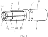
FIG. 1 is a schematic diagram of a charging terminal according to an embodiment of the present disclosure; and -
FIG. 2 is a schematic diagram of mating between a charging base and a charging gun according to an embodiment of the present disclosure. - The reference numerals in the specification are as follows:
- 1. Connecting base; 11. Connecting base body; 12. Connecting hole; 13. Annular groove; 14. Conductive layer; 15. Gap
- 2. Insertion portion; 21. Insertion hole; 22. Elastic piece; 221. Elastic transition piece; 222. First connecting section; 223. Second connecting section; 224. Third connecting section; 2241. Inclined guide surface; 23. Slit; 225. concave surface;
- 3. Pin terminal;
- 4. Charging base housing; 41. Cavity.
- To make the technical problems to be resolved in the present disclosure, technical solutions, and beneficial effects of the present disclosure clearer, the present disclosure is further described in detail below with reference to drawings and embodiments. It should be understood that the specific embodiments described herein are merely used for explaining the present disclosure, but are not intended to limit the present disclosure.
- A technical problem to be resolved in the present disclosure is as follows: For a problem that it cannot be determined whether an existing charging gun is in proper contact with a charging base when the charging gun is inserted into a charging base, a charging terminal and a charging base are provided.
- In the charging terminal provided in the embodiments of the present disclosure, an elastic transition piece is arranged on an end of an elastic piece. The elastic transition piece is in a shape of a concave surface. When a pin terminal is inserted into an insertion hole, and the elastic piece is expanded to exhibit a slight deformation, the elastic transition piece has a retracting effect on a main elastic piece. In this way, multiple elastic pieces converge toward a central shaft of the insertion hole, which can enhance elasticity and rebound forces of the elastic pieces, and the multiple elastic pieces can clamp the pin terminal, to form a clamping structure, ensure that the charging gun is in proper contact, and avoid local heating as a result of insufficient contact.
- As shown in
FIG. 1 to FIG. 2 , according to an aspect, an embodiment of the present disclosure provides a charging terminal. The charging terminal includes a connecting base 1 and aninsertion portion 2. The charging terminal is arranged inside the charging base. The connecting base 1 is configured to connect to a cable of the charging base. The connecting base 1 and the cable are connected with each other inside the charging base. Theinsertion portion 2 includes multipleelastic pieces 22 arranged at intervals along a circumferential direction of the charging terminal. Aninsertion hole 21 configured to allow insertion of apin terminal 3 of a charging gun is formed on inner sides of the multipleelastic pieces 22. When the charging gun is inserted into and mates with the charging base, thepin terminal 3 is inserted into theinsertion hole 21, to charge a new energy vehicle. - Each of the
elastic pieces 22 includes a main elastic piece and anelastic transition piece 221. Theelastic transition piece 221 is connected between the main elastic piece and the connecting base 1. In an axial direction of the charging terminal, a right end part of the main elastic piece is connected with a left end part of theelastic transition piece 221, and a right end part of theelastic transition piece 221 is connected with a left end part of the connecting base 1. Left and right are distinguished based on a left/right direction inFIG. 1 . Aconcave surface 225 recessed toward an axis of theinsertion hole 21 is arranged on an outer peripheral surface of theelastic transition piece 221. Theconcave surface 225 is connected between an outer peripheral surface of the main elastic piece and an outer peripheral surface of the connecting base 1, to form a transition connecting between the main elastic piece and the connecting base 1. When thepin terminal 3 of the charging gun is inserted into theinsertion hole 21, the multipleelastic pieces 22 expand outward. Multipleelastic pieces 22 around theinsertion hole 21 are expanded as a result of the insertion of thepin terminal 3, and therefore theelastic pieces 22 are deformed. The outer peripheral surface of theelastic transition piece 221 is designed in a shape of a concave surface. Theelastic transition piece 221 can retract the main elastic piece, to cause multiple main elastic pieces to tend to converge toward a central shaft of theinsertion hole 21, to cause the multiple main elastic pieces to be tightly attached to an outer peripheral surface of thepin terminal 3 of the charging gun. - In the charging terminal provided in the embodiments of the present disclosure, the
elastic transition piece 221 is arranged on an end of theelastic piece 22. Theelastic transition piece 221 is in the shape of the concave surface. When thepin terminal 3 is inserted into theinsertion hole 21, and theelastic piece 22 is expanded to exhibit a slight deformation, theelastic transition piece 221 has the retracting effect on the main elastic piece. In this way, the multipleelastic pieces 22 converge toward the central shaft, which can enhance elasticity and rebound forces of theelastic pieces 22, and the multipleelastic pieces 22 can clamp thepin terminal 3, to form a clamping structure, ensure that the charging gun is in proper contact, and avoid local heating as a result of insufficient contact. - Furthermore, since the
elastic pieces 22 can clamp thepin terminal 3, during the insertion of thepin terminal 3, the charging terminal can scrape off an oxide layer and a foreign object on a surface of thepin terminal 3, so that thepin terminal 3 of the charging gun becomes smooth with use. In this way, a problem of heating up of thepin terminal 3 of the charging gun as a result of an increased resistance after oxidation is resolved. - In an embodiment, as shown in
FIG. 1 , the multipleelastic pieces 22 are arranged at intervals, and aslit 23 is formed between two adjacentelastic pieces 22. In this way, theinsertion portion 2 can tightly clamp thepin terminal 3. In addition, adaptability can be improved. When a size error of thepin terminal 3 is excessively large, the insertion and mating between the charging base and the charging gun can be achieved. - In an embodiment, 2 to 8
elastic pieces 22 are arranged. Optionally, in this embodiment, 6elastic pieces 22 are arranged. - In an embodiment, the
concave surface 225 extends along the circumferential direction of the charging terminal.Concave surfaces 225 of multipleelastic transition pieces 221 are on a same circumference. Multipleconcave surfaces 225 form an annular structure. A sectional shape of the concave surface may include but is not limited to, a V shape, a U shape, and an arc shape. Optionally, theconcave surface 225 is a concave curved surface. - In an embodiment, as shown in
FIG. 1 andFIG. 2 , a section size of the connecting base 1 is greater than a section size of the main elastic piece. A first end of theelastic transition piece 221 is connected with the connecting base 1. A second end of theelastic transition piece 221 is connected with the main elastic piece. A section size of the first end of theelastic transition piece 221 is greater than a section size of the second end of theelastic transition piece 221. A middle part of theelastic transition piece 221 is recessed toward the central shaft of theinsertion hole 21, so that the entireelastic transition piece 221 is in a shape of the concave curved surface. In this way, theelastic piece 22 has a relatively desirable rebound force when being deformed as a result of outward expansion, theelastic piece 22 can recover well after thepin terminal 3 is unplugged, and full contact between thepin terminal 3 and the charging terminal is not affected after next insertion of thepin terminal 3. - In an embodiment, as shown in
FIG. 2 , an end of theinsertion hole 21 is open and an other end is enclosed. The open end of theinsertion hole 21 is configured to allow insertion of thepin terminal 3. The enclosed end of theinsertion hole 21 extends to a connectingbase body 11. - In an embodiment, as shown in
FIG. 1 andFIG. 2 , the main elastic piece includes a first connectingsection 222, a second connectingsection 223 and a third connectingsection 224. An end of the first connectingsection 222 is connected with theelastic transition piece 221. Theconcave surface 225 is connected with an outer surface of the first connectingsection 222. The second connectingsection 223 is connected between an other end of the first connectingsection 222 and the third connectingsection 224. Along a radial direction of theinsertion hole 21, a thickness of the second connectingsection 223 is less than a thickness of the first connectingsection 222 and a thickness of the third connectingsection 224. A length of the first connectingsection 222 is greater than a length of the second connectingsection 223. The length of the second connectingsection 223 is greater than a length of the third connectingsection 224. The length and the thickness of the first connectingsection 222 are slightly larger, which can ensure rigidity of theelastic piece 22, and prevent a situation in which theelastic piece 22 does not easily recover from deformation as a result of insufficient rigidity of theelastic piece 22. The length and the thickness of the second connectingsection 223 are slightly small, and the second connecting section is arranged close to the open end of theinsertion hole 21, which can ensure elasticity of theelastic piece 22, have a certain degree of deformation, and can tightly clamp thepin terminal 3. Through reasonable distribution of the rigidity and the elasticity of theelastic piece 22, theelastic piece 22 can resist deformation and recover from deformation while clamping tightly thepin terminal 3, such that subsequent insertions of thepin terminal 3 are not affected, and a service life is improved. - In an embodiment, as shown in
FIG. 1 andFIG. 2 , aninclined guide surface 2241 is arranged on the third connectingsection 224. Along a radial direction of the charging terminal, theinclined guide surface 2241 is inclined from an inner surface of the third connectingsection 224 toward the outer surface, so that the open end of theinsertion hole 21 is in a shape of a trumpet away from theinsertion hole 21, which facilitates the insertion of thepin terminal 3. Theinclined guide surface 2241 has a guiding effect during the insertion of thepin terminal 3, to guide an insertion direction of thepin terminal 3. - In an embodiment, as shown in
FIG. 1 andFIG. 2 , the connecting base 1 includes the connectingbase body 11 and a connectinghole 12 provided inside the connectingbase body 11. The connectinghole 12 is configured to connect to the cable of the charging base. A shape and a size of the connectinghole 12 may be determined based on an actual case. The size of the connectinghole 12 can have specific impact on a current carrying capacity of the charging terminal. - In an embodiment, a
conductive layer 14 is arranged on an inner wall of the connectinghole 12. Through arrangement of theconductive layer 14, the current carrying capacity of the charging terminal can be enhanced, and the current carrying capacity can be increased to 320 A. Through the increase of the current carrying capacity of the charging terminal, a temperature change curve of the charging gun during charging is optimized, to prevent a high temperature from generating an adverse effect on a head of the charging gun. Optionally, theconductive layer 14 is a tin layer. - In an embodiment, as shown in
FIG. 1 , the connecting base 1 further includes anannular groove 13 provided on the connectingbase body 11. Theannular groove 13 is engaged with the charging base, which can prevent the charging terminal from moving along the axial direction. - According to an aspect, an embodiment of the present disclosure provides a charging base. The charging base includes a charging
base housing 4 and the above charging terminal. The charging terminal is arranged in the chargingbase housing 4. Multiple types of terminals are arranged on the charging base. Each terminal may adopt a structure the same as the charging terminal. - In an embodiment, as shown in
FIG. 2 , acavity 41 for accommodating the charging terminal is provided in the chargingbase housing 4. Agap 15 exists between an inner wall of thecavity 41 and the charging terminal, so that the charging terminal is not tightly clamped in thecavity 41. When an insertion position of thepin terminal 3 is not on a centerline of thecavity 41, the charging terminal slightly moves following the position of thepin terminal 3, to reduce damage to the charging terminal. - The above descriptions are merely exemplary embodiments of the present disclosure, but are not intended to limit the present disclosure. Any modification, equivalent replacement, improvement, and the like made within the spirit and principle of the present disclosure shall fall within the protection scope of the present disclosure.
Claims (20)
- A charging terminal, comprising a connecting base (1) and an insertion portion (2), the charging terminal being arranged inside a charging base, the connecting base (1) being configured to connect to a cable of the charging base, the insertion portion (2) comprising a plurality of elastic pieces (22) arranged at intervals along a circumferential direction of the charging terminal, and an insertion hole (21) configured to allow insertion of a pin terminal (3) of a charging gun being formed on inner sides of the plurality of elastic pieces (22);each of the elastic pieces (22) comprising a main elastic piece and an elastic transition piece (221), the elastic transition piece (221) being connected between the main elastic piece and the connecting base (1), and a concave surface (225) recessed toward an axis of the insertion hole (21) being arranged on an outer peripheral surface of the elastic transition piece (221); andwhen the pin terminal (3) of the charging gun is inserted into the insertion hole (21), the plurality of elastic pieces (22) expanding outward, and the elastic transition piece (221) being configured to retract the main elastic piece, to cause a plurality of main elastic pieces to tend to converge toward a central shaft of the insertion hole (21), to cause the plurality of main elastic pieces to be tightly attached to an outer peripheral surface of the pin terminal (3) of the charging gun.
- The charging terminal according to claim 1, wherein the concave surface (225) extends along a circumferential direction of the charging terminal; concave surfaces (225) of a plurality of elastic transition pieces (221) are on a same circumference; and the concave surfaces (225) of the plurality of elastic transition pieces (221) form an annular structure.
- The charging terminal according to claim 1 or 2, wherein the plurality of elastic pieces are arranged at intervals; and a slit (23) is formed between two adjacent elastic pieces.
- The charging terminal according to any of claims 1 to 3, wherein a section size of the connecting base (1) is greater than a section size of the main elastic piece; a first end of the elastic transition piece (221) is connected with the connecting base (1); a second end of the elastic transition piece (221) is connected with the main elastic piece; and a section size of the first end of the elastic transition piece (221) is greater than a section size of the second end of the elastic transition piece (221).
- The charging terminal according to any of claims 1 to 4, wherein the main elastic piece comprises a first connecting section (222), a second connecting section (223), and a third connecting section (224); an end of the first connecting section (222) is connected with the elastic transition piece (221); the second connecting section (223) is connected between an other end of the first connecting section (222) and the third connecting section (224); and along a radial direction of the insertion hole (21), a thickness of the second connecting section (223) is less than a thickness of the first connecting section (222) and a thickness of the third connecting section (224).
- The charging terminal according to claim 5, wherein a length of the first connecting section (222) is greater than a length of the second connecting section (223); and the length of the second connecting section (223) is greater than a length of the third connecting section (224).
- The charging terminal according to claim 5 or 6, wherein an inclined guide surface (2241) is arranged on the third connecting section (224); and the inclined guide surface (2241) is inclined from an inner side surface of the third connecting section (224) toward an outer side surface.
- The charging terminal according to any of claims 1 to 7, wherein the connecting base (1) comprises a connecting base body (11) and a connecting hole (12) provided inside the connecting base body; and the connecting hole (12) is configured to connect to the cable of the charging base.
- The charging terminal according to claim 8, wherein a conductive layer (14) is arranged on an inner wall of the connecting hole (12).
- The charging terminal according to claim 9, wherein the conductive layer (14) is a tin layer.
- The charging terminal according to any of claims 8 to 10, wherein the connecting base (1) further comprises an annular groove (13) provided on the connecting base body (11); and the annular groove (13) is configured to be engaged with the charging base.
- The charging terminal according to any of claims 1 to 11, wherein an end of the insertion hole (21) is open an other end is enclosed; the open end of the insertion hole (21) is configured to allow insertion of the pin terminal (3); and the enclosed end of the insertion hole (21) extends to the connecting base body (11).
- A charging terminal, comprising a connecting base (1) and an insertion portion (2), the insertion portion (2) comprising a plurality of elastic pieces (22) arranged at intervals along a circumferential direction of the charging terminal, and an insertion hole (21) being formed on inner sides of the plurality of elastic pieces (22); and
each of the elastic pieces (22) comprising a main elastic piece and an elastic transition piece (221), the elastic transition piece (221) being connected between the main elastic piece and the connecting base (1), and a concave surface (225) recessed toward an axis of the insertion hole (21) being arranged on an outer peripheral surface of the elastic transition piece (221). - The charging terminal according to claim 13, wherein the concave surface (225) extends along a circumferential direction of the charging terminal; concave surfaces (225) of a plurality of elastic transition pieces (221) are on a same circumference; and the concave surfaces (225) of the plurality of elastic transition pieces (221) form an annular structure.
- The charging terminal according to claim 13 or 14, wherein a section size of the connecting base (1) is greater than a section size of the main elastic piece; a first end of the elastic transition piece (221) is connected with the connecting base (1); a second end of the elastic transition piece (221) is connected with the main elastic piece; and a section size of the first end of the elastic transition piece (221) is greater than a section size of the second end of the elastic transition piece (221).
- The charging terminal according to any of claims 13 to 15, wherein the main elastic piece comprises a first connecting section (222), a second connecting section (223), and a third connecting section (224); an end of the first connecting section (222) is connected with the elastic transition piece (221); the second connecting section (223) is connected between an other end of the first connecting section (222) and the third connecting section (224); and along a radial direction of the insertion hole (21), a thickness of the second connecting section (223) is less than a thickness of the first connecting section (222) and a thickness of the third connecting section (224).
- The charging terminal according to claim 16, wherein an inclined guide surface (2241) is arranged on the third connecting section (224); and the inclined guide surface (2241) is inclined from an inner side surface of the third connecting section (224) toward an outer side surface.
- The charging terminal according to any of claims 13 to 17, wherein the connecting base (1) comprises a connecting base body (11) and a connecting hole (12) provided inside the connecting base body.
- A charging base, comprising a charging base housing (4) and the charging terminal according to any of claims 1 to 12 or the charging terminal according to any of claims 13 to 18.
- The charging base according to claim 19, wherein a cavity (41) for accommodating the charging terminal is provided in the charging base housing; and a gap (15) exists between an inner wall of the cavity and the charging terminal.
Applications Claiming Priority (2)
| Application Number | Priority Date | Filing Date | Title |
|---|---|---|---|
| CN202221338538.XU CN217788913U (en) | 2022-05-31 | 2022-05-31 | Charging terminal and charging seat |
| PCT/CN2023/077358 WO2023231460A1 (en) | 2022-05-31 | 2023-02-21 | Charging terminal and charging base |
Publications (2)
| Publication Number | Publication Date |
|---|---|
| EP4521564A1 true EP4521564A1 (en) | 2025-03-12 |
| EP4521564A4 EP4521564A4 (en) | 2025-08-06 |
Family
ID=83918775
Family Applications (1)
| Application Number | Title | Priority Date | Filing Date |
|---|---|---|---|
| EP23814659.1A Pending EP4521564A4 (en) | 2022-05-31 | 2023-02-21 | CHARGING DEVICE AND CHARGING BASE |
Country Status (4)
| Country | Link |
|---|---|
| US (1) | US20250050757A1 (en) |
| EP (1) | EP4521564A4 (en) |
| CN (1) | CN217788913U (en) |
| WO (1) | WO2023231460A1 (en) |
Families Citing this family (2)
| Publication number | Priority date | Publication date | Assignee | Title |
|---|---|---|---|---|
| CN217788913U (en) * | 2022-05-31 | 2022-11-11 | 比亚迪股份有限公司 | Charging terminal and charging seat |
| CN116724881B (en) * | 2023-06-30 | 2024-07-09 | 广西壮族自治区农业科学院 | Sugarcane pollinator |
Family Cites Families (11)
| Publication number | Priority date | Publication date | Assignee | Title |
|---|---|---|---|---|
| JP5229507B2 (en) * | 2010-03-30 | 2013-07-03 | 株式会社デンソー | Vehicle distance sensor |
| CN208797260U (en) * | 2018-09-25 | 2019-04-26 | 深圳乔合里科技股份有限公司 | Detachable cradle |
| CN209169444U (en) * | 2018-12-12 | 2019-07-26 | 深圳市沃尔新能源电气科技股份有限公司 | Connect female terminal, socket and electric connector |
| WO2020235355A1 (en) * | 2019-05-22 | 2020-11-26 | 住友電装株式会社 | Connection terminal and connector |
| CN214898976U (en) * | 2021-03-31 | 2021-11-26 | 柏绍文 | Practical electric connector and electric connection mechanism |
| CN113131253B (en) * | 2021-04-14 | 2022-07-26 | 惠州尼索科连接技术有限公司 | Split type jack |
| CN215184555U (en) * | 2021-05-31 | 2021-12-14 | 深圳市沃尔新能源电气科技股份有限公司 | Connecting terminal, charging seat and electric automobile |
| CN113410686A (en) * | 2021-07-15 | 2021-09-17 | 长春捷翼汽车零部件有限公司 | Plug-in terminal |
| CN113410687A (en) * | 2021-07-15 | 2021-09-17 | 长春捷翼汽车零部件有限公司 | Plug terminal, plug connection structure and plug terminal assembly |
| CN215896789U (en) * | 2021-09-15 | 2022-02-22 | 长春捷翼汽车零部件有限公司 | Charging seat and motor vehicle of terminal high accuracy centering |
| CN217788913U (en) * | 2022-05-31 | 2022-11-11 | 比亚迪股份有限公司 | Charging terminal and charging seat |
-
2022
- 2022-05-31 CN CN202221338538.XU patent/CN217788913U/en active Active
-
2023
- 2023-02-21 WO PCT/CN2023/077358 patent/WO2023231460A1/en not_active Ceased
- 2023-02-21 EP EP23814659.1A patent/EP4521564A4/en active Pending
-
2024
- 2024-10-28 US US18/928,558 patent/US20250050757A1/en active Pending
Also Published As
| Publication number | Publication date |
|---|---|
| WO2023231460A1 (en) | 2023-12-07 |
| CN217788913U (en) | 2022-11-11 |
| US20250050757A1 (en) | 2025-02-13 |
| EP4521564A4 (en) | 2025-08-06 |
Similar Documents
| Publication | Publication Date | Title |
|---|---|---|
| US20250050757A1 (en) | Charging terminal and charging base | |
| CN101785152B (en) | Separable loadbreak connector and system | |
| CN116154509A (en) | Connector | |
| US7037127B2 (en) | Low force electrical contact | |
| CN218513727U (en) | Jack and connector using the jack | |
| CN113131253B (en) | Split type jack | |
| CN106887735A (en) | A kind of electric connector and its wire spring socket | |
| CN218070267U (en) | Electric connection terminal | |
| WO2024045612A1 (en) | Welding-free jack used for circuit board | |
| CN212380615U (en) | Claw spring assembling jack component for electric connector | |
| WO2024198905A1 (en) | Cylindrical terminal, electrically conductive structure, and charging base | |
| CN118156874A (en) | A connection structure, a charging seat and an electric transmission structure | |
| CN114725713B (en) | Jack contact and use connector of the jack contact | |
| CN213520395U (en) | Double-drum spring structure of contact pin plug bush | |
| CN108879161A (en) | A kind of high current terminal structure | |
| CN223066500U (en) | Spring claw contact piece with anti-falling structure | |
| CN221783474U (en) | Charging needle conductor on charging gun, charging gun | |
| CN223390803U (en) | Replaceable split groove terminal | |
| CN223729066U (en) | Electric connector and electric connection kit | |
| CN114628193A (en) | Contact assembly of arc extinguish chamber and manufacturing method of moving arc contact of arc extinguish chamber | |
| CN223858474U (en) | Charging terminal and socket with split groove structure | |
| CN219843171U (en) | Terminal plug-in structure and electric device | |
| CN223052550U (en) | Conductive ring for shaft | |
| CN221407703U (en) | Plug bush and electric connector | |
| CN221353208U (en) | Spring plate socket terminal |
Legal Events
| Date | Code | Title | Description |
|---|---|---|---|
| STAA | Information on the status of an ep patent application or granted ep patent |
Free format text: STATUS: THE INTERNATIONAL PUBLICATION HAS BEEN MADE |
|
| PUAI | Public reference made under article 153(3) epc to a published international application that has entered the european phase |
Free format text: ORIGINAL CODE: 0009012 |
|
| STAA | Information on the status of an ep patent application or granted ep patent |
Free format text: STATUS: REQUEST FOR EXAMINATION WAS MADE |
|
| 17P | Request for examination filed |
Effective date: 20241204 |
|
| AK | Designated contracting states |
Kind code of ref document: A1 Designated state(s): AL AT BE BG CH CY CZ DE DK EE ES FI FR GB GR HR HU IE IS IT LI LT LU LV MC ME MK MT NL NO PL PT RO RS SE SI SK SM TR |
|
| A4 | Supplementary search report drawn up and despatched |
Effective date: 20250704 |
|
| RIC1 | Information provided on ipc code assigned before grant |
Ipc: H01R 13/629 20060101AFI20250630BHEP Ipc: H01R 13/64 20060101ALI20250630BHEP Ipc: H01R 13/02 20060101ALI20250630BHEP Ipc: H01R 13/11 20060101ALI20250630BHEP Ipc: B60L 53/16 20190101ALI20250630BHEP Ipc: H01R 13/03 20060101ALI20250630BHEP |
|
| DAV | Request for validation of the european patent (deleted) | ||
| DAX | Request for extension of the european patent (deleted) |