EP4521538A1 - Battery pack - Google Patents
Battery pack Download PDFInfo
- Publication number
- EP4521538A1 EP4521538A1 EP22968346.1A EP22968346A EP4521538A1 EP 4521538 A1 EP4521538 A1 EP 4521538A1 EP 22968346 A EP22968346 A EP 22968346A EP 4521538 A1 EP4521538 A1 EP 4521538A1
- Authority
- EP
- European Patent Office
- Prior art keywords
- pressure relief
- battery pack
- tray
- holes
- height direction
- Prior art date
- Legal status (The legal status is an assumption and is not a legal conclusion. Google has not performed a legal analysis and makes no representation as to the accuracy of the status listed.)
- Pending
Links
Images


Classifications
-
- H—ELECTRICITY
- H01—ELECTRIC ELEMENTS
- H01M—PROCESSES OR MEANS, e.g. BATTERIES, FOR THE DIRECT CONVERSION OF CHEMICAL ENERGY INTO ELECTRICAL ENERGY
- H01M50/00—Constructional details or processes of manufacture of the non-active parts of electrochemical cells other than fuel cells, e.g. hybrid cells
- H01M50/30—Arrangements for facilitating escape of gases
- H01M50/35—Gas exhaust passages comprising elongated, tortuous or labyrinth-shaped exhaust passages
- H01M50/367—Internal gas exhaust passages forming part of the battery cover or case; Double cover vent systems
-
- H—ELECTRICITY
- H01—ELECTRIC ELEMENTS
- H01M—PROCESSES OR MEANS, e.g. BATTERIES, FOR THE DIRECT CONVERSION OF CHEMICAL ENERGY INTO ELECTRICAL ENERGY
- H01M50/00—Constructional details or processes of manufacture of the non-active parts of electrochemical cells other than fuel cells, e.g. hybrid cells
- H01M50/20—Mountings; Secondary casings or frames; Racks, modules or packs; Suspension devices; Shock absorbers; Transport or carrying devices; Holders
- H01M50/204—Racks, modules or packs for multiple batteries or multiple cells
- H01M50/207—Racks, modules or packs for multiple batteries or multiple cells characterised by their shape
- H01M50/213—Racks, modules or packs for multiple batteries or multiple cells characterised by their shape adapted for cells having curved cross-section, e.g. round or elliptic
-
- H—ELECTRICITY
- H01—ELECTRIC ELEMENTS
- H01M—PROCESSES OR MEANS, e.g. BATTERIES, FOR THE DIRECT CONVERSION OF CHEMICAL ENERGY INTO ELECTRICAL ENERGY
- H01M10/00—Secondary cells; Manufacture thereof
- H01M10/60—Heating or cooling; Temperature control
- H01M10/65—Means for temperature control structurally associated with the cells
- H01M10/658—Means for temperature control structurally associated with the cells by thermal insulation or shielding
-
- H—ELECTRICITY
- H01—ELECTRIC ELEMENTS
- H01M—PROCESSES OR MEANS, e.g. BATTERIES, FOR THE DIRECT CONVERSION OF CHEMICAL ENERGY INTO ELECTRICAL ENERGY
- H01M50/00—Constructional details or processes of manufacture of the non-active parts of electrochemical cells other than fuel cells, e.g. hybrid cells
- H01M50/20—Mountings; Secondary casings or frames; Racks, modules or packs; Suspension devices; Shock absorbers; Transport or carrying devices; Holders
- H01M50/244—Secondary casings; Racks; Suspension devices; Carrying devices; Holders characterised by their mounting method
-
- H—ELECTRICITY
- H01—ELECTRIC ELEMENTS
- H01M—PROCESSES OR MEANS, e.g. BATTERIES, FOR THE DIRECT CONVERSION OF CHEMICAL ENERGY INTO ELECTRICAL ENERGY
- H01M50/00—Constructional details or processes of manufacture of the non-active parts of electrochemical cells other than fuel cells, e.g. hybrid cells
- H01M50/20—Mountings; Secondary casings or frames; Racks, modules or packs; Suspension devices; Shock absorbers; Transport or carrying devices; Holders
- H01M50/249—Mountings; Secondary casings or frames; Racks, modules or packs; Suspension devices; Shock absorbers; Transport or carrying devices; Holders specially adapted for aircraft or vehicles, e.g. cars or trains
-
- H—ELECTRICITY
- H01—ELECTRIC ELEMENTS
- H01M—PROCESSES OR MEANS, e.g. BATTERIES, FOR THE DIRECT CONVERSION OF CHEMICAL ENERGY INTO ELECTRICAL ENERGY
- H01M50/00—Constructional details or processes of manufacture of the non-active parts of electrochemical cells other than fuel cells, e.g. hybrid cells
- H01M50/20—Mountings; Secondary casings or frames; Racks, modules or packs; Suspension devices; Shock absorbers; Transport or carrying devices; Holders
- H01M50/258—Modular batteries; Casings provided with means for assembling
-
- H—ELECTRICITY
- H01—ELECTRIC ELEMENTS
- H01M—PROCESSES OR MEANS, e.g. BATTERIES, FOR THE DIRECT CONVERSION OF CHEMICAL ENERGY INTO ELECTRICAL ENERGY
- H01M50/00—Constructional details or processes of manufacture of the non-active parts of electrochemical cells other than fuel cells, e.g. hybrid cells
- H01M50/20—Mountings; Secondary casings or frames; Racks, modules or packs; Suspension devices; Shock absorbers; Transport or carrying devices; Holders
- H01M50/262—Mountings; Secondary casings or frames; Racks, modules or packs; Suspension devices; Shock absorbers; Transport or carrying devices; Holders with fastening means, e.g. locks
-
- H—ELECTRICITY
- H01—ELECTRIC ELEMENTS
- H01M—PROCESSES OR MEANS, e.g. BATTERIES, FOR THE DIRECT CONVERSION OF CHEMICAL ENERGY INTO ELECTRICAL ENERGY
- H01M50/00—Constructional details or processes of manufacture of the non-active parts of electrochemical cells other than fuel cells, e.g. hybrid cells
- H01M50/20—Mountings; Secondary casings or frames; Racks, modules or packs; Suspension devices; Shock absorbers; Transport or carrying devices; Holders
- H01M50/289—Mountings; Secondary casings or frames; Racks, modules or packs; Suspension devices; Shock absorbers; Transport or carrying devices; Holders characterised by spacing elements or positioning means within frames, racks or packs
-
- H—ELECTRICITY
- H01—ELECTRIC ELEMENTS
- H01M—PROCESSES OR MEANS, e.g. BATTERIES, FOR THE DIRECT CONVERSION OF CHEMICAL ENERGY INTO ELECTRICAL ENERGY
- H01M50/00—Constructional details or processes of manufacture of the non-active parts of electrochemical cells other than fuel cells, e.g. hybrid cells
- H01M50/30—Arrangements for facilitating escape of gases
- H01M50/35—Gas exhaust passages comprising elongated, tortuous or labyrinth-shaped exhaust passages
- H01M50/358—External gas exhaust passages located on the battery cover or case
-
- H—ELECTRICITY
- H01—ELECTRIC ELEMENTS
- H01M—PROCESSES OR MEANS, e.g. BATTERIES, FOR THE DIRECT CONVERSION OF CHEMICAL ENERGY INTO ELECTRICAL ENERGY
- H01M50/00—Constructional details or processes of manufacture of the non-active parts of electrochemical cells other than fuel cells, e.g. hybrid cells
- H01M50/30—Arrangements for facilitating escape of gases
- H01M50/383—Flame arresting or ignition-preventing means
-
- Y—GENERAL TAGGING OF NEW TECHNOLOGICAL DEVELOPMENTS; GENERAL TAGGING OF CROSS-SECTIONAL TECHNOLOGIES SPANNING OVER SEVERAL SECTIONS OF THE IPC; TECHNICAL SUBJECTS COVERED BY FORMER USPC CROSS-REFERENCE ART COLLECTIONS [XRACs] AND DIGESTS
- Y02—TECHNOLOGIES OR APPLICATIONS FOR MITIGATION OR ADAPTATION AGAINST CLIMATE CHANGE
- Y02E—REDUCTION OF GREENHOUSE GAS [GHG] EMISSIONS, RELATED TO ENERGY GENERATION, TRANSMISSION OR DISTRIBUTION
- Y02E60/00—Enabling technologies; Technologies with a potential or indirect contribution to GHG emissions mitigation
- Y02E60/10—Energy storage using batteries
Definitions
- the present disclosure relates to the technical field of battery packs, and in particular, to a battery pack.
- the demand for lightweight vehicles has been increasing.
- the endurance range has always been a bottleneck restricting performance development.
- improving the endurance range usually starts from the perspective of increasing the total energy of the battery, which usually includes increasing the energy density of the battery pack or increasing the number of modules.
- a double-layer module is usually arranged. The appearance of the double-layer module structure can effectively utilize the envelope space and improve the endurance range of electric vehicles.
- the present disclosure provides a battery pack to prevent thermal runaway from spreading.
- the battery pack includes:
- each of the supporting trays includes a tray body formed with a mounting groove and tray extension members arranged at circumferential edges of the tray body.
- Each of the tray bodies is penetrated by a plurality of the through holes along its own height direction.
- the pressure relief cavity is formed between a pair of the tray bodies arranged along the height direction, and the module bracket is arranged between a pair of the tray extension members arranged along the height direction.
- the tray extension member and the module bracket are both in a rectangular ring shape.
- it further includes: a fireproof board arranged between a pair of the tray bodies arranged along the height direction, and the through holes of the upper tray body and the through holes of the lower tray body are separated by the fireproof board.
- the box is provided with side beams and a plurality of first cross beams; where the side beams are enclosed to form a frame structure; the side beams are provided with the third pressure relief channels; the plurality of the first cross beams are arranged inside the frame structure and connected to the side beams, the plurality of the first cross beams separate a plurality of areas in the frame structure, and each of the areas is provided with the battery module.
- the first cross beam is provided with a second pressure relief channel, and the first pressure relief channel, the pressure relief hole, the second pressure relief channel and the third pressure relief channel are in communication.
- a pair of the supporting trays arranged along the height direction are symmetrically arranged, and the tray extension member located at a lower side is provided with a plurality of the pressure relief holes.
- the pressure relief holes, the second pressure relief channel and the third pressure relief channel are provided with a plurality of the pressure relief holes.
- the side beam is provided with an explosion-proof valve, and the explosion-proof valve is communicated with the third pressure relief channel.
- the module bracket and a pair of the tray extension members arranged along the height direction are connected by locking members to clamp the fireproof board.
- the battery pack provided in the embodiments of the present disclosure has the following beneficial effects:
- orientations or positional relationships indicated by terms such as “up”, “down”, “front”, “back”, “left”, “right”, “vertical”, “horizontal”, “top”, “bottom”, “inside”, “outside”, etc. are based on the orientations or positional relationships shown in the accompanying drawings, and are merely for the convenience of describing the present disclosure and simplifying the description, rather than indicating or implying that the referred device or element must have a specific orientation, be constructed and operated in a specific orientation, and therefore should not be understood as a limitation on the present disclosure.
- FIGs. 1 to 6 A battery pack and an electrical device according to the embodiments of the present disclosure will be described below with reference to FIGs. 1 to 6 .
- Some embodiments of the present disclosure will be described in detail below with reference to the accompanying drawings. In the absence of conflict, the following embodiments and features in the embodiments may be combined with each other.
- the demand for lightweight vehicles has been increasing.
- the endurance range has always been a bottleneck restricting performance development.
- improving the endurance range usually starts from the perspective of increasing the total energy of the battery, which usually includes increasing the energy density of the battery pack or increasing the number of modules.
- a double-layer module is usually arranged. The appearance of the double-layer module structure can effectively utilize the envelope space and improve the endurance range of electric vehicles.
- the battery pack in the embodiments of the present disclosure is designed with special exhaust and pressure relief structures for the double-layer module, so as to guide away these gases and flames in a directed manner when thermal runaway occurs to prevent the spread of thermal runaway.
- each support tray 11 includes a tray body 113 formed with a mounting groove and a tray extension member 114 arranged at circumferential edges of the tray body 113.
- Each tray body 113 is provided with the plurality of through holes 111 running through its own height direction.
- the pressure relief cavity 3 is formed between a pair of tray bodies 113 arranged along the height direction, and the module bracket 2 is arranged between a pair of tray extension members 114 arranged along the height direction.
- the battery module of the battery pack in the embodiments of the present disclosure is provided with a pair of support trays 11. Due to the tray body 113 with the mounting groove being formed on the support tray 11, this means that the tray body 113 itself has a certain height, so that an installation gap is formed between the pair of tray extension members 114 for installing the module bracket 2. Therefore, the cell group 12 is correspondingly installed in the mounting groove of the tray body 113, the module bracket 2 is correspondingly installed on the tray extension members 114, and the cell group 12 is relatively arranged in the module bracket 2, so that the cell group 12 and the module bracket 2 partially overlap in height, making the structure more compact, reducing the thickness of the battery pack to a certain extent, and achieving miniaturization and portability.
- the battery pack in the embodiments of the present disclosure includes battery module, a module bracket 2 and a box 6.
- the battery module includes a pair of battery assemblies 1 stacked up and down along a height direction.
- Each battery assembly 1 includes a support tray 11 and a cell group 12.
- the support tray 11 is penetrated with a plurality of through holes 111 along its own height direction.
- the pressure relief valves of a plurality of cells in the cell group 12 are arranged at the plurality of through holes 111 in a one-to-one correspondence manner, and the pressure relief valves of a pair of cell groups 12 arranged along the height direction are arranged facing each other.
- the support tray 11 is further provided with a plurality of pressure relief holes 112.
- a module bracket 2 is arranged between a pair of support trays 11 arranged along the height direction, and the module bracket 2 is provided with first pressure relief channels 21.
- a pressure relief cavity 3 is provided between a pair of support trays 11 arranged along the height direction.
- the through holes 111, the pressure relief cavity 3, the first pressure relief channels 21 and the pressure relief holes 112 are in communication.
- the battery module is arranged in the box 6.
- the box 6 is provided with third pressure relief channels 71, and the third pressure relief channels 71 are in communication with the pressure relief holes 112.
- the cells in the battery assemblies 1 are cylindrical cells. Since the pressure relief valve of the cylindrical cell is arranged at a bottom of the cell itself, the double-layer battery assemblies 1 adopt an installation structure in which the bottoms of the cells are arranged facing each other.
- the gas and flame generated will be concentrated through the through hole 111 in the pressure relief cavity 3 formed between the pair of the support trays 11 arranged along the height direction, and then the gas and flame generated will flow to the first pressure relief channel 21 of the module bracket 2, and then flow to the pressure relief hole 112 of the support tray 11, and finally flow into the third pressure relief channel 71 of the box 6.
- These gases and flames are guided away through the third pressure relief channel 71, effectively preventing the gas and flame from spreading randomly inside the battery pack, effectively preventing the spread of thermal runaway, and preventing more serious fires or explosions.
- the arrangement of a double-layer module in the battery pack can effectively improve the endurance range of electric vehicles, but it will increase the thickness of the battery pack. Therefore, in order to reduce the overall thickness of the battery pack, the structure of the support tray 11 is improved, and the installation position of the module bracket 2 is also adjusted accordingly, which reduces the thickness of the battery pack to a certain extent and achieves miniaturization and portability.
- each support tray 11 includes a tray body 113 formed with a mounting groove and a tray extension member 114 arranged at circumferential edges of the tray body 113.
- Each tray body 113 is provided with the plurality of through holes 111 running through its own height direction.
- the pressure relief cavity 3 is formed between a pair of tray bodies 113 arranged along the height direction, and the module bracket 2 is arranged between a pair of tray extension members 114 arranged along the height direction.
- the battery module of the battery pack in the embodiments of the present disclosure is provided with a pair of support trays 11. Due to the tray body 113 with the mounting groove being formed on the support tray 11, this means that the tray body 113 itself has a certain height, so that an installation gap is formed between the pair of tray extension members 114 for installing the module bracket 2. Therefore, the cell group 12 is correspondingly installed in the mounting groove of the tray body 113, the module bracket 2 is correspondingly installed on the tray extension members 114, and the cell group 12 is relatively arranged in the module bracket 2, so that the cell group 12 and the module bracket 2 partially overlap in height, making the structure more compact, reducing the thickness of the battery pack to a certain extent, and achieving miniaturization and portability.
- the tray extension member 114 and the module bracket 2 may be in a circular shape.
- the battery pack in the embodiments of the present disclosure further includes a fireproof board 5.
- the fireproof board 5 is arranged between a pair of tray bodies 113 arranged along the height direction.
- the through holes 111 of the upper tray body 113 and the through holes 111 of the tray body 113 are separated by the fireproof board 5.
- the gas and flame generated will spray toward the fireproof board 5, flow along the fireproof board 5 toward the edges of the support tray 11, then flow to the first pressure relief channel 21 of the module bracket 2, and then flow into the pressure relief hole 112 of the support tray 11, and finally flow into the third pressure relief channel 71 of the box 6.
- These gases and flames are guided away through the third pressure relief channel 71, effectively preventing the gases and flames from spreading randomly inside the battery pack, effectively preventing the spread of thermal runaway, and preventing more serious fires or explosions.
- it also effectively prevents thermal runaway caused by the gas and flame generated spraying to the bottoms of the cells of the opposite module, and prevents the thermal runaway from spreading between the double-layer module.
- the fireproof board 5 may be a mica board, for example, a high-temperature resistant mica board, which may be formed by bonding, heating and pressing mica paper and organic silicone glue, where the mica content is about 90% and the organic silicone glue content is 10%.
- the battery pack improves the structure of the box 6.
- the box 6 is provided with side beams 7 and a plurality of first cross beams 4.
- the side beams 7 are enclosed to form a frame structure.
- the side beams 7 are provided with the third pressure relief channels 71.
- the plurality of first cross beams 4 are arranged inside the frame structure and connected to the side beams 7.
- the plurality of first cross beams 4 separate a plurality of areas within the frame structure, and each of the areas is provided with the battery module.
- the first cross beam 4 is provided with a second pressure relief channel 41.
- the first pressure relief channel 21, the pressure relief hole 112, the second pressure relief channel 41 and the third pressure relief channel 71 are in communication.
- the plurality of battery modules and the plurality of first cross beams 4 of the battery pack in the embodiments of the present disclosure are arranged at staggered intervals, so that each battery module is arranged between two first cross beams 4.
- the gas and flame generated will be concentrated through the through holes 111 in the pressure relief cavity 3 formed between a pair of the support trays 11 arranged along the height direction, and then the gas and flame generated will flow to the first pressure relief channel 21 of the module bracket 2, and then flow to the pressure relief hole 112 of the support tray 11, first flow into the second pressure relief channel 41 of the first cross beam 4, and then flow into the third pressure relief channel 71 of the box 6.
- These gases and flames are guided away through the third pressure relief channel 71, effectively preventing the gas and flame from spreading randomly inside the battery pack, effectively preventing the spread of thermal runaway, and preventing more serious fires or explosions.
- the gas and flame generated by the battery module will flow to the first cross beams 4 on both sides, and then be guided away through the second pressure relief channel 41, effectively preventing the gas and flame from spreading randomly inside the battery pack, and effectively preventing the spread of thermal runaway, so as to prevent more serious fires or explosions.
- a flow guide structure of the gas and flame generated can be specifically referred to FIGs. 1 to 6 .
- the side beam 7 is provided with an exhaust hole, which is in communication with the outside of the box and the third pressure relief channel 71.
- the exhaust hole is blocked with an explosion-proof valve 72, and the explosion-proof valve 72 is in communication with the third pressure relief channel 71.
- the side beam 7 may be specifically in a concave shape.
- the gas and flame generated will flow to the second pressure relief channel 41 in the first cross beam 4, and then flow to the third pressure relief channel 71 of the side beam 7, and finally explode at the explosion-proof valve 72, automatically opens to release pressure, so as to prevent the battery pack from exploding.
- the fireproof board 5 is arranged between a pair of tray bodies 113 arranged along the height direction, the gas and flame generated would spray toward the fireproof board 5 when thermal runaway occurs. Therefore, the fireproof board 5 needs to be fixed to prevent it from deflecting caused by being sprayed during thermal runaway.
- the battery pack clamps the fireproof board 5 through a clamping structure to fix the fireproof board 5.
- the module bracket 2 and a pair of tray extension members 114 arranged along the height direction are connected by locking members 8 to clamp the fireproof board 5.
- the battery pack locks a pair of tray extension members 114 to the module bracket 2 through the locking members 8, and then clamps the fireproof board 5 through the pair of tray bodies 113 to achieve the fixation of the fireproof board 5 and prevent it from being deflecting caused by sprayed during thermal runaway.
- the locking member 8 may be specifically a bolt or a screw.
- the embodiments of the present disclosure disclose not only a battery pack, but also an electrical device including the battery pack.
- the electrical device may be, but is not limited to, a mobile phone, a tablet, a laptop, an electric toy, an electric tool, an electric vehicle, an electric car, a ship, a spacecraft, etc.
- the electric toy may include a fixed or mobile electric toy, such as a game console, an electric car toy, an electric ship toy and an electric airplane toy, etc.
- the spacecraft may include an airplane, a rocket, a space shuttle and a spaceship, etc.
- the power tool includes a metal-cutting power tool, a grinding power tool, an assembly power tool and a railway power tool, such as an electric drill, an electric grinder, an electric wrench, an electric screwdriver, an electric hammer, an impact drill, a concrete vibrator and an electric planer.
- a metal-cutting power tool such as an electric drill, an electric grinder, an electric wrench, an electric screwdriver, an electric hammer, an impact drill, a concrete vibrator and an electric planer.
Landscapes
- Chemical & Material Sciences (AREA)
- Chemical Kinetics & Catalysis (AREA)
- Electrochemistry (AREA)
- General Chemical & Material Sciences (AREA)
- Engineering & Computer Science (AREA)
- Aviation & Aerospace Engineering (AREA)
- Manufacturing & Machinery (AREA)
- Battery Mounting, Suspending (AREA)
- Gas Exhaust Devices For Batteries (AREA)
Abstract
Description
- The present disclosure claims priority to
Chinese Patent Application No. 202211598515.7, filed to the Chinese Patent Office on December 14, 2022 - The present disclosure relates to the technical field of battery packs, and in particular, to a battery pack.
- In recent years, the demand for lightweight vehicles has been increasing. Especially in the field of new energy vehicles, the endurance range has always been a bottleneck restricting performance development. In related technologies, improving the endurance range usually starts from the perspective of increasing the total energy of the battery, which usually includes increasing the energy density of the battery pack or increasing the number of modules. In order to improve the space utilization of electric vehicles, a double-layer module is usually arranged. The appearance of the double-layer module structure can effectively utilize the envelope space and improve the endurance range of electric vehicles.
- In the design process of double-layer module battery packs in related technologies, it is usually difficult to design a special exhaust and pressure relief channel due to difficulty in sealing. Due to the lack of special exhaust and pressure relief channels in the battery pack with a double-layer module, when the cells in the module experience thermal runaway, a large amount of gas accompanied by flames is instantly released from the cells. Due to the lack of directional exhaust channels to guide away these gases and flames, they will randomly spread inside the battery pack, which can easily ignite other components and cause thermal runaway in other normally used cells, causing the thermal runaway to spread and easily lead to fire or explosion, thus, there is room for improvement.
- In a aspect, the present disclosure provides a battery pack to prevent thermal runaway from spreading.
- The battery pack includes:
- a battery module, including a pair of battery assemblies stacked along a height direction;
- where each of the battery assemblies includes a support tray and a cell group; where the support tray is penetrated with a plurality of through holes along its height direction, and pressure relief valves of a plurality of single cells in the cell group are arranged at the plurality of through holes in a one-to-one correspondence manner, and the pressure relief valves of a pair of cell groups arranged along the height direction are arranged facing each other; and the support tray is further provided with a plurality of pressure relief holes;
- a module bracket is arranged between a pair of the support trays arranged along the height direction, and the module bracket is provided with first pressure relief channels; where a pressure relief cavity is arranged between a pair of the support trays arranged along the height direction, and the through holes, the pressure relief cavity, the first pressure relief channels and the pressure relief holes are in communication;
- a box, where the battery module is arranged in the box, and the box is provided with a third pressure relief channel, and the third pressure relief channel is in communication with the pressure relief holes.
- In one embodiment, each of the supporting trays includes a tray body formed with a mounting groove and tray extension members arranged at circumferential edges of the tray body. Each of the tray bodies is penetrated by a plurality of the through holes along its own height direction. The pressure relief cavity is formed between a pair of the tray bodies arranged along the height direction, and the module bracket is arranged between a pair of the tray extension members arranged along the height direction.
- In one embodiment, the tray extension member and the module bracket are both in a rectangular ring shape.
- In one embodiment, it further includes: a fireproof board arranged between a pair of the tray bodies arranged along the height direction, and the through holes of the upper tray body and the through holes of the lower tray body are separated by the fireproof board.
- In one embodiment, the box is provided with side beams and a plurality of first cross beams; where the side beams are enclosed to form a frame structure; the side beams are provided with the third pressure relief channels;
the plurality of the first cross beams are arranged inside the frame structure and connected to the side beams, the plurality of the first cross beams separate a plurality of areas in the frame structure, and each of the areas is provided with the battery module. - In one embodiment, the first cross beam is provided with a second pressure relief channel, and the first pressure relief channel, the pressure relief hole, the second pressure relief channel and the third pressure relief channel are in communication.
- In one embodiment, a pair of the supporting trays arranged along the height direction are symmetrically arranged, and the tray extension member located at a lower side is provided with a plurality of the pressure relief holes. The pressure relief holes, the second pressure relief channel and the third pressure relief channel.
- In one embodiment, the side beam is provided with an explosion-proof valve, and the explosion-proof valve is communicated with the third pressure relief channel.
- In one embodiment, the module bracket and a pair of the tray extension members arranged along the height direction are connected by locking members to clamp the fireproof board.
- In summary, the battery pack provided in the embodiments of the present disclosure has the following beneficial effects:
- In actual applications, in the double-layer battery assemblies in the battery pack of the embodiments of the present disclosure, the cells in the battery assemblies are cylindrical cells. Since the explosion-proof valve of the cylindrical cell is arranged at a bottom of the cell itself, the double-layer battery assemblies adopt an installation structure in which the bottoms of the cells are arranged facing each other. When the battery experiences thermal runaway, the gas and flame generated will be concentrated through the through hole in the pressure relief cavity formed between the pair of the support trays arranged along the height direction, and then the gas and flame generated will flow to the first pressure relief channel of the module bracket, and then flow to the pressure relief hole of the support tray, and finally flow into the third pressure relief channel of the box. These gases and flames are guided away through the third pressure relief channel, which effectively prevents the gas and flame from spreading randomly inside the battery pack, effectively prevents the spread of thermal runaway, and prevents more serious fires or explosions.
- Additional aspects and advantages of the present disclosure will be given in part in the description below, and in part will become apparent from the description below, or will be learned through the practice of the present disclosure.
-
-
FIG. 1 is a schematic structural diagram of a battery pack in embodiments of the present disclosure; -
FIG. 2 is a schematic diagram of the internal structure of a battery pack in embodiments of the present disclosure; -
FIG. 3 is a partial enlarged view of A inFIG. 2 ; -
FIG. 4 is another schematic diagram of the internal structure of a battery pack in embodiments of the present disclosure; -
FIG. 5 is a schematic structural diagram of a support tray in embodiments of the present disclosure; -
FIG. 6 is a schematic structural diagram of a module bracket in embodiments of the present disclosure; -
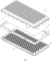
FIG. 7 is a schematic diagram of a disassembled state of a battery pack in embodiments of the present disclosure; - Reference numerals in the drawings: 1, battery assembly; 11, support tray; 111, through hole; 112, pressure relief hole; 113, tray body; 114, tray extension member; 12, cell group; 2, module bracket; 21, first pressure relief channel; 3, pressure relief cavity; 4, first cross beam; 41, second pressure relief channel; 5, fireproof board; 6, box; 7, side beam; 71, third pressure relief channel; 72, explosion-proof valve; 8, locking member.
- In the description of the present disclosure, it should be noted that orientations or positional relationships indicated by terms such as "up", "down", "front", "back", "left", "right", "vertical", "horizontal", "top", "bottom", "inside", "outside", etc., are based on the orientations or positional relationships shown in the accompanying drawings, and are merely for the convenience of describing the present disclosure and simplifying the description, rather than indicating or implying that the referred device or element must have a specific orientation, be constructed and operated in a specific orientation, and therefore should not be understood as a limitation on the present disclosure.
- Unless otherwise defined, all technical and scientific terms used herein have the same meaning as commonly understood by one of ordinary skill in the art to which this disclosure belongs. The terms used herein in the description of the present disclosure are for the purpose of describing specific embodiments only and are not intended to limit the present disclosure.
- A battery pack and an electrical device according to the embodiments of the present disclosure will be described below with reference to
FIGs. 1 to 6 . Some embodiments of the present disclosure will be described in detail below with reference to the accompanying drawings. In the absence of conflict, the following embodiments and features in the embodiments may be combined with each other. - In recent years, the demand for lightweight vehicles has been increasing. Especially in the field of new energy vehicles, the endurance range has always been a bottleneck restricting performance development. In related technologies, improving the endurance range usually starts from the perspective of increasing the total energy of the battery, which usually includes increasing the energy density of the battery pack or increasing the number of modules. In order to improve the space utilization of electric vehicles, a double-layer module is usually arranged. The appearance of the double-layer module structure can effectively utilize the envelope space and improve the endurance range of electric vehicles.
- In the design process of battery packs with double-layer modules in related technologies, it is usually difficult to design special exhaust and pressure relief channels due to difficulty in sealing. Due to the lack of special exhaust and pressure relief channels in the battery pack with a double-layer module, when the cells in the module experience thermal runaway, a large amount of gas accompanied by flames is instantly released from the cells. Due to the lack of directional exhaust channels to guide away these gases and flames, they will randomly spread inside the battery pack, which can easily ignite other components and cause thermal runaway in other normally used cells, causing the thermal runaway to spread and easily lead to fire or explosion, thus, there is room for improvement.
- In view of this, the battery pack in the embodiments of the present disclosure is designed with special exhaust and pressure relief structures for the double-layer module, so as to guide away these gases and flames in a directed manner when thermal runaway occurs to prevent the spread of thermal runaway.
- Specifically, please refer to
FIGs. 1 to 6 , in the battery pack of the embodiments of the present disclosure, eachsupport tray 11 includes atray body 113 formed with a mounting groove and atray extension member 114 arranged at circumferential edges of thetray body 113. Eachtray body 113 is provided with the plurality of throughholes 111 running through its own height direction. Thepressure relief cavity 3 is formed between a pair oftray bodies 113 arranged along the height direction, and themodule bracket 2 is arranged between a pair oftray extension members 114 arranged along the height direction. - In actual applications, the battery module of the battery pack in the embodiments of the present disclosure is provided with a pair of
support trays 11. Due to thetray body 113 with the mounting groove being formed on thesupport tray 11, this means that thetray body 113 itself has a certain height, so that an installation gap is formed between the pair oftray extension members 114 for installing themodule bracket 2. Therefore, thecell group 12 is correspondingly installed in the mounting groove of thetray body 113, themodule bracket 2 is correspondingly installed on thetray extension members 114, and thecell group 12 is relatively arranged in themodule bracket 2, so that thecell group 12 and themodule bracket 2 partially overlap in height, making the structure more compact, reducing the thickness of the battery pack to a certain extent, and achieving miniaturization and portability. - Specifically, please refer to
FIGs. 1 to 6 , the battery pack in the embodiments of the present disclosure includes battery module, amodule bracket 2 and a box 6. - In one embodiment, the battery module includes a pair of battery assemblies 1 stacked up and down along a height direction. Each battery assembly 1 includes a
support tray 11 and acell group 12. Thesupport tray 11 is penetrated with a plurality of throughholes 111 along its own height direction. The pressure relief valves of a plurality of cells in thecell group 12 are arranged at the plurality of throughholes 111 in a one-to-one correspondence manner, and the pressure relief valves of a pair ofcell groups 12 arranged along the height direction are arranged facing each other. Thesupport tray 11 is further provided with a plurality of pressure relief holes 112. Amodule bracket 2 is arranged between a pair ofsupport trays 11 arranged along the height direction, and themodule bracket 2 is provided with firstpressure relief channels 21. where apressure relief cavity 3 is provided between a pair ofsupport trays 11 arranged along the height direction. The throughholes 111, thepressure relief cavity 3, the firstpressure relief channels 21 and thepressure relief holes 112 are in communication. The battery module is arranged in the box 6. The box 6 is provided with thirdpressure relief channels 71, and the thirdpressure relief channels 71 are in communication with the pressure relief holes 112. - In actual applications, in the double-layer battery assemblies 1 in the battery pack of the embodiments of the present disclosure, the cells in the battery assemblies 1 are cylindrical cells. Since the pressure relief valve of the cylindrical cell is arranged at a bottom of the cell itself, the double-layer battery assemblies 1 adopt an installation structure in which the bottoms of the cells are arranged facing each other. When the battery experiences thermal runaway, the gas and flame generated will be concentrated through the through
hole 111 in thepressure relief cavity 3 formed between the pair of thesupport trays 11 arranged along the height direction, and then the gas and flame generated will flow to the firstpressure relief channel 21 of themodule bracket 2, and then flow to thepressure relief hole 112 of thesupport tray 11, and finally flow into the thirdpressure relief channel 71 of the box 6. These gases and flames are guided away through the thirdpressure relief channel 71, effectively preventing the gas and flame from spreading randomly inside the battery pack, effectively preventing the spread of thermal runaway, and preventing more serious fires or explosions. - It was found in further applications that the arrangement of a double-layer module in the battery pack can effectively improve the endurance range of electric vehicles, but it will increase the thickness of the battery pack. Therefore, in order to reduce the overall thickness of the battery pack, the structure of the
support tray 11 is improved, and the installation position of themodule bracket 2 is also adjusted accordingly, which reduces the thickness of the battery pack to a certain extent and achieves miniaturization and portability. - Specifically, please refer to
FIGs. 1 to 6 , in the battery pack of the embodiments of the present disclosure, eachsupport tray 11 includes atray body 113 formed with a mounting groove and atray extension member 114 arranged at circumferential edges of thetray body 113. Eachtray body 113 is provided with the plurality of throughholes 111 running through its own height direction. Thepressure relief cavity 3 is formed between a pair oftray bodies 113 arranged along the height direction, and themodule bracket 2 is arranged between a pair oftray extension members 114 arranged along the height direction. - In actual applications, the battery module of the battery pack in the embodiments of the present disclosure is provided with a pair of
support trays 11. Due to thetray body 113 with the mounting groove being formed on thesupport tray 11, this means that thetray body 113 itself has a certain height, so that an installation gap is formed between the pair oftray extension members 114 for installing themodule bracket 2. Therefore, thecell group 12 is correspondingly installed in the mounting groove of thetray body 113, themodule bracket 2 is correspondingly installed on thetray extension members 114, and thecell group 12 is relatively arranged in themodule bracket 2, so that thecell group 12 and themodule bracket 2 partially overlap in height, making the structure more compact, reducing the thickness of the battery pack to a certain extent, and achieving miniaturization and portability. - It can be understood that when the battery experiences thermal runaway, the gas and flame generated will be concentrated in the
pressure relief cavity 3, and then the gas and flame generated will flow toward edges of thesupport tray 11, then flow to the firstpressure relief channel 21 of themodule bracket 2, and then flow to thepressure relief hole 112 of thesupport tray 11, and finally flow into the thirdpressure relief channel 71 of the box 6. These gases and flames are guided away through the thirdpressure relief channel 71, effectively preventing the gas and flame from spreading randomly inside the battery pack, effectively preventing the spread of thermal runaway, and preventing more serious fires or explosions. - Existing battery packs are usually made into a square shell shape. In order to adapt to the square shell shape, in the battery pack of the embodiments of the present disclosure, the
tray extension member 114 and themodule bracket 2 are both in a rectangular ring shape. - Of course, in some other embodiments, the
tray extension member 114 and themodule bracket 2 may be in a circular shape. - It was found in further applications that due to the double-layer module configuration is employed in the battery pack, when the cells in one layer of
cell group 12 experience thermal runaway, the gas and flame generated will spray toward bottoms of the cells in anopposite cell group 12, thereby causing thermal runaway. Therefore, in order to prevent thermal runaway caused by the gas and flame generated spraying to the bottoms of the cells of the opposite module, the battery pack is blocked by setting afireproof board 5, to prevent the thermal runaway from spreading between the double-layer module. - Specifically, please refer to
FIGs. 1 to 6 , the battery pack in the embodiments of the present disclosure further includes afireproof board 5. Thefireproof board 5 is arranged between a pair oftray bodies 113 arranged along the height direction. The throughholes 111 of theupper tray body 113 and the throughholes 111 of thetray body 113 are separated by thefireproof board 5. - In actual applications, when thermal runaway occurs in the cells in one layer of
cell group 12 of the battery pack in the embodiments of the present application, the gas and flame generated will spray toward thefireproof board 5, flow along thefireproof board 5 toward the edges of thesupport tray 11, then flow to the firstpressure relief channel 21 of themodule bracket 2, and then flow into thepressure relief hole 112 of thesupport tray 11, and finally flow into the thirdpressure relief channel 71 of the box 6. These gases and flames are guided away through the thirdpressure relief channel 71, effectively preventing the gases and flames from spreading randomly inside the battery pack, effectively preventing the spread of thermal runaway, and preventing more serious fires or explosions. In addition, it also effectively prevents thermal runaway caused by the gas and flame generated spraying to the bottoms of the cells of the opposite module, and prevents the thermal runaway from spreading between the double-layer module. - The
fireproof board 5 may be a mica board, for example, a high-temperature resistant mica board, which may be formed by bonding, heating and pressing mica paper and organic silicone glue, where the mica content is about 90% and the organic silicone glue content is 10%. - It was found in further applications that in order to increase the battery capacity of the battery pack, a plurality of battery modules are usually arranged in the battery pack. In order to enable the plurality of battery modules to reasonably discharge the gas and flame generated when thermal runaway occurs, the battery pack improves the structure of the box 6.
- Specifically, please refer to
FIGs. 1 to 6 , in the battery pack in the embodiments of the present disclosure, the box 6 is provided withside beams 7 and a plurality of first cross beams 4. The side beams 7 are enclosed to form a frame structure. The side beams 7 are provided with the thirdpressure relief channels 71. The plurality offirst cross beams 4 are arranged inside the frame structure and connected to the side beams 7. The plurality offirst cross beams 4 separate a plurality of areas within the frame structure, and each of the areas is provided with the battery module. - In other embodiments, the
first cross beam 4 is provided with a secondpressure relief channel 41. The firstpressure relief channel 21, thepressure relief hole 112, the secondpressure relief channel 41 and the thirdpressure relief channel 71 are in communication. - In actual applications, the plurality of battery modules and the plurality of
first cross beams 4 of the battery pack in the embodiments of the present disclosure are arranged at staggered intervals, so that each battery module is arranged between two first cross beams 4. When the battery experiences thermal runaway, the gas and flame generated will be concentrated through the throughholes 111 in thepressure relief cavity 3 formed between a pair of thesupport trays 11 arranged along the height direction, and then the gas and flame generated will flow to the firstpressure relief channel 21 of themodule bracket 2, and then flow to thepressure relief hole 112 of thesupport tray 11, first flow into the secondpressure relief channel 41 of thefirst cross beam 4, and then flow into the thirdpressure relief channel 71 of the box 6. These gases and flames are guided away through the thirdpressure relief channel 71, effectively preventing the gas and flame from spreading randomly inside the battery pack, effectively preventing the spread of thermal runaway, and preventing more serious fires or explosions. - Moreover, from a positional point of view, the gas and flame generated by the battery module will flow to the first cross beams 4 on both sides, and then be guided away through the second
pressure relief channel 41, effectively preventing the gas and flame from spreading randomly inside the battery pack, and effectively preventing the spread of thermal runaway, so as to prevent more serious fires or explosions. - A flow guide structure of the gas and flame generated can be specifically referred to
FIGs. 1 to 6 . Theside beam 7 is provided with an exhaust hole, which is in communication with the outside of the box and the thirdpressure relief channel 71. The exhaust hole is blocked with an explosion-proof valve 72, and the explosion-proof valve 72 is in communication with the thirdpressure relief channel 71. Theside beam 7 may be specifically in a concave shape. - In actual applications, when thermal runaway occurs in the battery module, the gas and flame generated will flow to the second
pressure relief channel 41 in thefirst cross beam 4, and then flow to the thirdpressure relief channel 71 of theside beam 7, and finally explode at the explosion-proof valve 72, automatically opens to release pressure, so as to prevent the battery pack from exploding. - It was found in further applications that since the
fireproof board 5 is arranged between a pair oftray bodies 113 arranged along the height direction, the gas and flame generated would spray toward thefireproof board 5 when thermal runaway occurs. Therefore, thefireproof board 5 needs to be fixed to prevent it from deflecting caused by being sprayed during thermal runaway. The battery pack clamps thefireproof board 5 through a clamping structure to fix thefireproof board 5. - Specifically, please refer to
FIGs. 1 to 6 , in the battery pack in the embodiments of the present disclosure, themodule bracket 2 and a pair oftray extension members 114 arranged along the height direction are connected by lockingmembers 8 to clamp thefireproof board 5. - In actual application, the battery pack locks a pair of
tray extension members 114 to themodule bracket 2 through the lockingmembers 8, and then clamps thefireproof board 5 through the pair oftray bodies 113 to achieve the fixation of thefireproof board 5 and prevent it from being deflecting caused by sprayed during thermal runaway. The lockingmember 8 may be specifically a bolt or a screw. - The embodiments of the present disclosure disclose not only a battery pack, but also an electrical device including the battery pack. The electrical device may be, but is not limited to, a mobile phone, a tablet, a laptop, an electric toy, an electric tool, an electric vehicle, an electric car, a ship, a spacecraft, etc. The electric toy may include a fixed or mobile electric toy, such as a game console, an electric car toy, an electric ship toy and an electric airplane toy, etc. The spacecraft may include an airplane, a rocket, a space shuttle and a spaceship, etc. The power tool includes a metal-cutting power tool, a grinding power tool, an assembly power tool and a railway power tool, such as an electric drill, an electric grinder, an electric wrench, an electric screwdriver, an electric hammer, an impact drill, a concrete vibrator and an electric planer.
Claims (10)
- A battery pack, comprising:a battery module comprising a pair of battery assemblies (1) stacked along a height direction;wherein each of the battery assemblies (1) comprises a support tray (11) and a cell group (12); wherein the support tray (11) is penetrated with a plurality of through holes (111) along its own height direction; pressure relief valves of a plurality of cells in the cell group (12) are arranged at the plurality of through holes (111) in a one-to-one correspondence manner, and the pressure relief valves of a pair of cell groups (12) arranged along the height direction are arranged facing each other; the support tray (11) is further provided with a plurality of pressure relief holes (112);a module bracket (2) arranged between a pair of the support trays (11) arranged along the height direction; wherein the module bracket (2) is provided with first pressure relief channels (21); wherein a pressure relief cavity (3) is provided between a pair of the support trays (11) arranged along the height direction; wherein the through holes (111), the pressure relief cavity (3), the first pressure relief channels (21) and the pressure relief holes (112) are in communication;a box (6), wherein the battery module is arranged in the box (6); the box (6) is provided with third pressure relief channels (71); wherein the third pressure relief channels (71) are in communication with the pressure relief holes (112).
- The battery pack according to claim 1, wherein each of the support trays (11) comprises a tray body (113) formed with a mounting groove and tray extension members (114) arranged at circumferential edges of the tray body (113); wherein each of the tray bodies (113) is provided with the plurality of through holes (111) running through its own height direction;
the pressure relief cavity (3) is formed between a pair of tray bodies (113) arranged along the height direction, and the module bracket (2) is arranged between a pair of tray extension members (114) arranged along the height direction. - The battery pack according to claim 2, wherein the tray extension member (114) and the module bracket (2) are both in a rectangular ring shape.
- The battery pack according to claim 2, further comprising:
a fireproof board (5) arranged between a pair of the tray bodies (113) arranged along the height direction; wherein the through holes (111) of the upper tray body (113) and the through holes (111) of the lower tray body (113) are separated by the fireproof board (5). - The battery pack according to claim 4, wherein the fireproof board (5) is a mica board.
- The battery pack according to any one of claims 2 to 5, wherein the box (6) is provided with side beams (7) and a plurality of first cross beams (4); wherein the side beams (7) are enclosed to form a frame structure; the side beams (7) are provided with the third pressure relief channels (71);
the plurality of the first cross beams (4) are arranged inside the frame structure and connected to the side beams (7); the plurality of the first cross beams (4) separate a plurality of areas within the frame structure, and each of the areas is provided with the battery module. - The battery pack according to claim 6, wherein the first cross beam (4) is provided with a second pressure relief channel (41); wherein the first pressure relief channel (21), the pressure relief hole (112), the second pressure relief channel (41) and the third pressure relief channel (71) are in communication.
- The battery pack according to claim 7, wherein a pair of the support trays (11) arranged along the height direction are symmetrically arranged, and the tray extension member (114) located at a lower side is provided with the plurality of the pressure relief holes (112); wherein the pressure relief holes (112), the second pressure relief channel (41) and the third pressure relief channel (71).
- The battery pack according to claim 6, wherein the side beam (7) is provided with an explosion-proof valve (72); wherein the explosion-proof valve (72) is communicated with the third pressure relief channel (71).
- The battery pack according to claim 4 or 5, wherein the module bracket (2) and a pair of tray extension members (114) arranged along the height direction are connected by locking members (8) to clamp the fireproof board (5).
Applications Claiming Priority (2)
| Application Number | Priority Date | Filing Date | Title |
|---|---|---|---|
| CN202211598515.7A CN115966837B (en) | 2022-12-14 | 2022-12-14 | Battery pack for double-layer module |
| PCT/CN2022/144223 WO2024124645A1 (en) | 2022-12-14 | 2022-12-30 | Battery pack |
Publications (2)
| Publication Number | Publication Date |
|---|---|
| EP4521538A1 true EP4521538A1 (en) | 2025-03-12 |
| EP4521538A4 EP4521538A4 (en) | 2025-09-10 |
Family
ID=87352086
Family Applications (1)
| Application Number | Title | Priority Date | Filing Date |
|---|---|---|---|
| EP22968346.1A Pending EP4521538A4 (en) | 2022-12-14 | 2022-12-30 | Battery pack |
Country Status (7)
| Country | Link |
|---|---|
| US (1) | US20260121215A1 (en) |
| EP (1) | EP4521538A4 (en) |
| JP (1) | JP7843862B2 (en) |
| KR (1) | KR20250012583A (en) |
| CN (1) | CN115966837B (en) |
| DE (1) | DE212022000408U1 (en) |
| WO (1) | WO2024124645A1 (en) |
Families Citing this family (9)
| Publication number | Priority date | Publication date | Assignee | Title |
|---|---|---|---|---|
| CN116526059A (en) * | 2023-04-28 | 2023-08-01 | 惠州亿纬锂能股份有限公司 | Battery pack |
| CN120432800A (en) * | 2024-02-04 | 2025-08-05 | 厦门新能达科技有限公司 | Battery packs and powered devices |
| WO2025008003A1 (en) * | 2024-02-05 | 2025-01-09 | 惠州亿纬锂能股份有限公司 | Battery pack |
| EP4621951A1 (en) * | 2024-03-22 | 2025-09-24 | Eve Energy Co., Ltd. | Battery and battery pack |
| US20250309466A1 (en) | 2024-03-29 | 2025-10-02 | Eve Energy Co., Ltd. | Pressure relief structure for double-layer battery and battery pack |
| CN222735271U (en) * | 2024-05-27 | 2025-04-08 | 欣旺达动力科技股份有限公司 | Battery packs and electrical equipment |
| CN223124115U (en) * | 2024-07-31 | 2025-07-18 | 宁德时代新能源科技股份有限公司 | Battery devices and power-consuming devices |
| KR20260031509A (en) * | 2024-08-29 | 2026-03-09 | 주식회사 엘지에너지솔루션 | Battery pack, and vehicle including the same |
| CN224110417U (en) * | 2025-01-24 | 2026-04-10 | 惠州亿纬锂能股份有限公司 | Battery cell fixing support and battery pack |
Family Cites Families (18)
| Publication number | Priority date | Publication date | Assignee | Title |
|---|---|---|---|---|
| JP4965750B2 (en) | 2010-07-30 | 2012-07-04 | パナソニック株式会社 | Battery system |
| KR20150059515A (en) * | 2013-11-22 | 2015-06-01 | 주식회사 엘지화학 | Battery Pack Having Means for Venting the Gas |
| JP2017004901A (en) | 2015-06-15 | 2017-01-05 | 株式会社オートネットワーク技術研究所 | Power storage module |
| CN110190211B (en) * | 2018-12-29 | 2020-03-31 | 比亚迪股份有限公司 | Battery tray, power battery package and vehicle |
| HUE061756T2 (en) | 2019-01-09 | 2023-08-28 | Byd Co Ltd | Single cell, power battery pack, and electric vehicle |
| KR102922132B1 (en) | 2020-04-29 | 2026-02-02 | 주식회사 엘지에너지솔루션 | Battery pack and device including the same |
| CN215816098U (en) * | 2021-06-04 | 2022-02-11 | 恒大新能源技术(深圳)有限公司 | Battery pack thermal runaway protection system and battery pack |
| CN216213676U (en) * | 2021-06-28 | 2022-04-05 | 长城汽车股份有限公司 | Box, battery package and vehicle under battery package |
| CN217387415U (en) * | 2021-12-15 | 2022-09-06 | 比亚迪股份有限公司 | Battery pack and vehicle |
| CN217158419U (en) * | 2022-01-29 | 2022-08-09 | 湖北亿纬动力有限公司 | Cylindrical battery pack |
| CN216958227U (en) * | 2022-03-15 | 2022-07-12 | 胡开发 | Heat dissipation mechanism for new energy automobile battery management |
| CN217788592U (en) * | 2022-06-28 | 2022-11-11 | 湖北亿纬动力有限公司 | Battery module, battery package and vehicle |
| CN218039573U (en) * | 2022-06-28 | 2022-12-13 | 湖北亿纬动力有限公司 | A battery pack and vehicle |
| CN115101885B (en) * | 2022-06-30 | 2026-07-31 | 湖北亿纬动力有限公司 | Directional exhaust battery module, battery box and battery pack |
| CN218039525U (en) * | 2022-08-11 | 2022-12-13 | 湖北亿纬动力有限公司 | Battery module and power battery |
| CN115275501B (en) | 2022-08-19 | 2024-07-23 | 东风汽车集团股份有限公司 | An explosion-proof battery module |
| CN115425359A (en) * | 2022-09-05 | 2022-12-02 | 广汽埃安新能源汽车有限公司 | A battery thermal runaway protection device |
| CN218939939U (en) * | 2022-12-14 | 2023-04-28 | 湖北亿纬动力有限公司 | Battery Packs for Dual Layer Modules |
-
2022
- 2022-12-14 CN CN202211598515.7A patent/CN115966837B/en active Active
- 2022-12-30 WO PCT/CN2022/144223 patent/WO2024124645A1/en not_active Ceased
- 2022-12-30 JP JP2024566600A patent/JP7843862B2/en active Active
- 2022-12-30 DE DE212022000408.6U patent/DE212022000408U1/en active Active
- 2022-12-30 EP EP22968346.1A patent/EP4521538A4/en active Pending
- 2022-12-30 KR KR1020247040375A patent/KR20250012583A/en active Pending
-
2024
- 2024-12-30 US US19/004,461 patent/US20260121215A1/en active Pending
Also Published As
| Publication number | Publication date |
|---|---|
| CN115966837A (en) | 2023-04-14 |
| DE212022000408U1 (en) | 2025-03-13 |
| WO2024124645A1 (en) | 2024-06-20 |
| JP7843862B2 (en) | 2026-04-10 |
| US20260121215A1 (en) | 2026-04-30 |
| EP4521538A4 (en) | 2025-09-10 |
| JP2025517179A (en) | 2025-06-03 |
| CN115966837B (en) | 2026-07-03 |
| KR20250012583A (en) | 2025-01-24 |
Similar Documents
| Publication | Publication Date | Title |
|---|---|---|
| US20260121215A1 (en) | Battery pack | |
| EP3809487B1 (en) | Protection plate, battery cell assembly, battery module and vehicle | |
| KR102910003B1 (en) | Battery module | |
| CN113966565A (en) | Battery pack and transportation equipment | |
| CN116325302B (en) | Batteries and electrical devices | |
| US20240413473A1 (en) | Pressure relief structue, battery cell, battery, and power consuming device | |
| CN218939939U (en) | Battery Packs for Dual Layer Modules | |
| CN221327956U (en) | Battery packs and electrical equipment | |
| US12476325B2 (en) | Cell assembly unit and battery pack including the same | |
| EP4567994A1 (en) | Discharge assembly, box body, battery, and electrical device | |
| CN117219954A (en) | Battery box, battery and electrical device | |
| WO2025223115A1 (en) | Battery pack and electric device | |
| US20260011863A1 (en) | Box body, battery, and electrical device | |
| CN116073067A (en) | A kind of battery and battery pack | |
| CN223347929U (en) | Battery pack and electric equipment | |
| CN222395000U (en) | Battery pack | |
| CN220368004U (en) | Battery shell and battery | |
| CN118017141A (en) | Battery packs and electrical equipment | |
| KR102885437B1 (en) | Battery and its manufacturing method, manufacturing device and electrical device | |
| CN117791008A (en) | Battery explosion-proof structure and battery | |
| US20250070355A1 (en) | Battery and electric device | |
| CN222601186U (en) | Battery box, battery and power utilization device | |
| CN223680315U (en) | Battery box and battery device | |
| CN222620012U (en) | Battery and vehicle | |
| CN222914973U (en) | Battery assembly box, battery pack and electric equipment |
Legal Events
| Date | Code | Title | Description |
|---|---|---|---|
| STAA | Information on the status of an ep patent application or granted ep patent |
Free format text: STATUS: THE INTERNATIONAL PUBLICATION HAS BEEN MADE |
|
| PUAI | Public reference made under article 153(3) epc to a published international application that has entered the european phase |
Free format text: ORIGINAL CODE: 0009012 |
|
| STAA | Information on the status of an ep patent application or granted ep patent |
Free format text: STATUS: REQUEST FOR EXAMINATION WAS MADE |
|
| 17P | Request for examination filed |
Effective date: 20241203 |
|
| AK | Designated contracting states |
Kind code of ref document: A1 Designated state(s): AL AT BE BG CH CY CZ DE DK EE ES FI FR GB GR HR HU IE IS IT LI LT LU LV MC ME MK MT NL NO PL PT RO RS SE SI SK SM TR |
|
| STAA | Information on the status of an ep patent application or granted ep patent |
Free format text: STATUS: EXAMINATION IS IN PROGRESS |
|
| A4 | Supplementary search report drawn up and despatched |
Effective date: 20250807 |
|
| RIC1 | Information provided on ipc code assigned before grant |
Ipc: H01M 50/358 20210101AFI20250801BHEP Ipc: H01M 50/249 20210101ALI20250801BHEP Ipc: H01M 50/258 20210101ALI20250801BHEP Ipc: H01M 50/213 20210101ALI20250801BHEP Ipc: H01M 50/244 20210101ALI20250801BHEP Ipc: H01M 50/289 20210101ALI20250801BHEP Ipc: H01M 50/383 20210101ALI20250801BHEP |
|
| 17Q | First examination report despatched |
Effective date: 20250821 |
|
| DAV | Request for validation of the european patent (deleted) | ||
| DAX | Request for extension of the european patent (deleted) |