EP4521532A1 - External battery module frame, battery module, and battery pack - Google Patents
External battery module frame, battery module, and battery pack Download PDFInfo
- Publication number
- EP4521532A1 EP4521532A1 EP24813088.2A EP24813088A EP4521532A1 EP 4521532 A1 EP4521532 A1 EP 4521532A1 EP 24813088 A EP24813088 A EP 24813088A EP 4521532 A1 EP4521532 A1 EP 4521532A1
- Authority
- EP
- European Patent Office
- Prior art keywords
- battery module
- side plate
- outer frame
- battery
- hanger
- Prior art date
- Legal status (The legal status is an assumption and is not a legal conclusion. Google has not performed a legal analysis and makes no representation as to the accuracy of the status listed.)
- Pending
Links
Images


Classifications
-
- H—ELECTRICITY
- H01—ELECTRIC ELEMENTS
- H01M—PROCESSES OR MEANS, e.g. BATTERIES, FOR THE DIRECT CONVERSION OF CHEMICAL ENERGY INTO ELECTRICAL ENERGY
- H01M10/00—Secondary cells; Manufacture thereof
- H01M10/60—Heating or cooling; Temperature control
- H01M10/65—Means for temperature control structurally associated with the cells
- H01M10/653—Means for temperature control structurally associated with the cells characterised by electrically insulating or thermally conductive materials
-
- H—ELECTRICITY
- H01—ELECTRIC ELEMENTS
- H01M—PROCESSES OR MEANS, e.g. BATTERIES, FOR THE DIRECT CONVERSION OF CHEMICAL ENERGY INTO ELECTRICAL ENERGY
- H01M50/00—Constructional details or processes of manufacture of the non-active parts of electrochemical cells other than fuel cells, e.g. hybrid cells
- H01M50/20—Mountings; Secondary casings or frames; Racks, modules or packs; Suspension devices; Shock absorbers; Transport or carrying devices; Holders
- H01M50/204—Racks, modules or packs for multiple batteries or multiple cells
- H01M50/207—Racks, modules or packs for multiple batteries or multiple cells characterised by their shape
-
- H—ELECTRICITY
- H01—ELECTRIC ELEMENTS
- H01M—PROCESSES OR MEANS, e.g. BATTERIES, FOR THE DIRECT CONVERSION OF CHEMICAL ENERGY INTO ELECTRICAL ENERGY
- H01M10/00—Secondary cells; Manufacture thereof
- H01M10/60—Heating or cooling; Temperature control
- H01M10/61—Types of temperature control
- H01M10/613—Cooling or keeping cold
-
- H—ELECTRICITY
- H01—ELECTRIC ELEMENTS
- H01M—PROCESSES OR MEANS, e.g. BATTERIES, FOR THE DIRECT CONVERSION OF CHEMICAL ENERGY INTO ELECTRICAL ENERGY
- H01M10/00—Secondary cells; Manufacture thereof
- H01M10/60—Heating or cooling; Temperature control
- H01M10/65—Means for temperature control structurally associated with the cells
- H01M10/655—Solid structures for heat exchange or heat conduction
- H01M10/6554—Rods or plates
-
- H—ELECTRICITY
- H01—ELECTRIC ELEMENTS
- H01M—PROCESSES OR MEANS, e.g. BATTERIES, FOR THE DIRECT CONVERSION OF CHEMICAL ENERGY INTO ELECTRICAL ENERGY
- H01M10/00—Secondary cells; Manufacture thereof
- H01M10/60—Heating or cooling; Temperature control
- H01M10/65—Means for temperature control structurally associated with the cells
- H01M10/655—Solid structures for heat exchange or heat conduction
- H01M10/6556—Solid parts with flow channel passages or pipes for heat exchange
-
- H—ELECTRICITY
- H01—ELECTRIC ELEMENTS
- H01M—PROCESSES OR MEANS, e.g. BATTERIES, FOR THE DIRECT CONVERSION OF CHEMICAL ENERGY INTO ELECTRICAL ENERGY
- H01M10/00—Secondary cells; Manufacture thereof
- H01M10/60—Heating or cooling; Temperature control
- H01M10/65—Means for temperature control structurally associated with the cells
- H01M10/656—Means for temperature control structurally associated with the cells characterised by the type of heat-exchange fluid
- H01M10/6567—Liquids
-
- H—ELECTRICITY
- H01—ELECTRIC ELEMENTS
- H01M—PROCESSES OR MEANS, e.g. BATTERIES, FOR THE DIRECT CONVERSION OF CHEMICAL ENERGY INTO ELECTRICAL ENERGY
- H01M10/00—Secondary cells; Manufacture thereof
- H01M10/60—Heating or cooling; Temperature control
- H01M10/65—Means for temperature control structurally associated with the cells
- H01M10/658—Means for temperature control structurally associated with the cells by thermal insulation or shielding
-
- H—ELECTRICITY
- H01—ELECTRIC ELEMENTS
- H01M—PROCESSES OR MEANS, e.g. BATTERIES, FOR THE DIRECT CONVERSION OF CHEMICAL ENERGY INTO ELECTRICAL ENERGY
- H01M50/00—Constructional details or processes of manufacture of the non-active parts of electrochemical cells other than fuel cells, e.g. hybrid cells
- H01M50/20—Mountings; Secondary casings or frames; Racks, modules or packs; Suspension devices; Shock absorbers; Transport or carrying devices; Holders
- H01M50/218—Mountings; Secondary casings or frames; Racks, modules or packs; Suspension devices; Shock absorbers; Transport or carrying devices; Holders characterised by the material
- H01M50/22—Mountings; Secondary casings or frames; Racks, modules or packs; Suspension devices; Shock absorbers; Transport or carrying devices; Holders characterised by the material of the casings or racks
- H01M50/222—Inorganic material
- H01M50/224—Metals
-
- H—ELECTRICITY
- H01—ELECTRIC ELEMENTS
- H01M—PROCESSES OR MEANS, e.g. BATTERIES, FOR THE DIRECT CONVERSION OF CHEMICAL ENERGY INTO ELECTRICAL ENERGY
- H01M50/00—Constructional details or processes of manufacture of the non-active parts of electrochemical cells other than fuel cells, e.g. hybrid cells
- H01M50/20—Mountings; Secondary casings or frames; Racks, modules or packs; Suspension devices; Shock absorbers; Transport or carrying devices; Holders
- H01M50/249—Mountings; Secondary casings or frames; Racks, modules or packs; Suspension devices; Shock absorbers; Transport or carrying devices; Holders specially adapted for aircraft or vehicles, e.g. cars or trains
-
- H—ELECTRICITY
- H01—ELECTRIC ELEMENTS
- H01M—PROCESSES OR MEANS, e.g. BATTERIES, FOR THE DIRECT CONVERSION OF CHEMICAL ENERGY INTO ELECTRICAL ENERGY
- H01M50/00—Constructional details or processes of manufacture of the non-active parts of electrochemical cells other than fuel cells, e.g. hybrid cells
- H01M50/20—Mountings; Secondary casings or frames; Racks, modules or packs; Suspension devices; Shock absorbers; Transport or carrying devices; Holders
- H01M50/262—Mountings; Secondary casings or frames; Racks, modules or packs; Suspension devices; Shock absorbers; Transport or carrying devices; Holders with fastening means, e.g. locks
-
- H—ELECTRICITY
- H01—ELECTRIC ELEMENTS
- H01M—PROCESSES OR MEANS, e.g. BATTERIES, FOR THE DIRECT CONVERSION OF CHEMICAL ENERGY INTO ELECTRICAL ENERGY
- H01M50/00—Constructional details or processes of manufacture of the non-active parts of electrochemical cells other than fuel cells, e.g. hybrid cells
- H01M50/20—Mountings; Secondary casings or frames; Racks, modules or packs; Suspension devices; Shock absorbers; Transport or carrying devices; Holders
- H01M50/289—Mountings; Secondary casings or frames; Racks, modules or packs; Suspension devices; Shock absorbers; Transport or carrying devices; Holders characterised by spacing elements or positioning means within frames, racks or packs
- H01M50/293—Mountings; Secondary casings or frames; Racks, modules or packs; Suspension devices; Shock absorbers; Transport or carrying devices; Holders characterised by spacing elements or positioning means within frames, racks or packs characterised by the material
-
- H—ELECTRICITY
- H01—ELECTRIC ELEMENTS
- H01M—PROCESSES OR MEANS, e.g. BATTERIES, FOR THE DIRECT CONVERSION OF CHEMICAL ENERGY INTO ELECTRICAL ENERGY
- H01M50/00—Constructional details or processes of manufacture of the non-active parts of electrochemical cells other than fuel cells, e.g. hybrid cells
- H01M50/50—Current conducting connections for cells or batteries
- H01M50/572—Means for preventing undesired use or discharge
- H01M50/584—Means for preventing undesired use or discharge for preventing incorrect connections inside or outside the batteries
- H01M50/59—Means for preventing undesired use or discharge for preventing incorrect connections inside or outside the batteries characterised by the protection means
- H01M50/593—Spacers; Insulating plates
-
- Y—GENERAL TAGGING OF NEW TECHNOLOGICAL DEVELOPMENTS; GENERAL TAGGING OF CROSS-SECTIONAL TECHNOLOGIES SPANNING OVER SEVERAL SECTIONS OF THE IPC; TECHNICAL SUBJECTS COVERED BY FORMER USPC CROSS-REFERENCE ART COLLECTIONS [XRACs] AND DIGESTS
- Y02—TECHNOLOGIES OR APPLICATIONS FOR MITIGATION OR ADAPTATION AGAINST CLIMATE CHANGE
- Y02E—REDUCTION OF GREENHOUSE GAS [GHG] EMISSIONS, RELATED TO ENERGY GENERATION, TRANSMISSION OR DISTRIBUTION
- Y02E60/00—Enabling technologies; Technologies with a potential or indirect contribution to GHG emissions mitigation
- Y02E60/10—Energy storage using batteries
Definitions
- the present disclosure relates to the technical field of batteries, in particular to a battery module outer frame, a battery module, and a battery pack.
- An outer frame of the battery module is generally formed by enclosing the left and right side plates and the front and rear end plates together.
- CTP cell to pack
- An outer frame of the battery module is generally formed by enclosing the left and right side plates and the front and rear end plates together.
- the side plate body is usually bent to form the hanger, but this processing method may not meet the processing of complex hanger structures, and also reduces the structural strength of the side plate.
- the present disclosure provides a battery module outer frame, a battery module, and a battery pack to solve the above technical problems.
- the present disclosure provides a battery module outer frame, including:
- the present disclosure provides a battery module including a module body and the battery module outer frame as described above, and the module body is fixed in the battery module outer frame.
- the present disclosure provides a battery pack including a box and the battery module as described above, and the battery module is disposed in the box.
- a battery module outer frame provided by the present disclosure includes a side plate and an end plate.
- the side plate extends along a first direction.
- the side plate includes a side plate body and a hanger.
- the side plate body and the hanger are integrally roll formed.
- the end plate extends along a second direction.
- the end plate and the side plate body are connected by laser welding.
- the first direction is perpendicular to the second direction. Since the side plate body and the hanger are integrally roll formed, the processing of the complex hanger is satisfied, and the structural strength of the whole side plate is improved. The processing is convenient, and the manufacturing cost of the side plate is reduced.
- the end plate and the side plate body may be connected by laser welding without laser filling welding, so that the welding process between the end plate and the side plate body is simple, and the manufacturing cost of the whole battery module outer frame is reduced.
- the processing process of the battery module is simplified and the manufacturing cost of the battery module is reduced.
- the processing process of the battery pack is simplified and the manufacturing cost of the battery pack is reduced.
- the battery pack disclosed in the embodiments further includes a liquid cooling plate 200.
- the liquid cooling plate 200 is disposed at a bottom of the box 300. A bottom of the battery module 100 is disposed on the liquid cooling plate 200.
- the liquid cooling plate 200 dissipates and cools the battery module 100 by liquid cooling to ensure the normal operation of the battery module 100.
- the battery module includes a module body and a battery module outer frame 10.
- the module body 20 is fixed in the battery module outer frame 10. It should be noted that in the embodiments, the module body 20 includes a plurality of cells arranged at intervals, and two module bodies 20 are arranged at intervals in each battery module outer frame 10 in the left-right direction, so that the battery module 100 has a double-row structure. In other embodiments, more module bodies 20 may also be installed in each battery module outer frame 10.
- the battery module outer frame 10 includes a side plate 1 and an end plate 2.
- the side plate 1 extends in a first direction (the front-rear direction in the figure).
- the end plate 2 extends in a second direction (the left-right direction in the figure).
- the end plate 2 is connected to the side plate 1.
- two side plates 1 are provided at intervals in the left-right direction
- two end plates 2 are provided at intervals in the front-rear direction.
- the two side plates 1 and the two end plates 2 are jointly enclosed to form a mounting frame, and the plurality of module bodies 20 are fixed in the mounting frame.
- the side plate body stamping die and the hanger stamping die respectively, and then the hanger is welded to the side plate body.
- the manufacturing process of the side plate is complicated, and the deformation between the side plate body and the hanger is easy to occur.
- the side plate body is usually bent to form hanger, but this processing method may not meet the processing of complex hanger structures, and also reduces the structural strength of the side plate.
- the side plate 1 provided in the embodiments includes a side plate body 11 and a hanger 12.
- the side plate body 11 and the hanger 12 are integrally roll formed, and the end plate 2 and the side plate body 11 are connected by laser welding. Since the side plate body 11 and the hanger 12 are integrally roll formed, the processing of the complex hanger 12 is satisfied, and the structural strength of the whole side plate 1 is improved. The processing is convenient, and the manufacturing cost of the side plate is reduced.
- the end plate 2 and the side plate body 11 may be connected by laser welding without laser filling welding, so that the welding process between the end plate 2 and the side plate body 11 is simple, and the manufacturing cost of the whole battery module outer frame 10 is reduced.
- the side plate 1 is made of a 5-series aluminum alloy material
- the end plate 2 is made of a 6-series aluminum alloy material, thereby ensuring that the side plate body 11 and the end plate 2 may be connected only by laser welding.
- the 5-series aluminum alloy has the advantage of being lightweight.
- the battery module outer frame 10 further includes a middle plate 4 extending in the front-rear direction.
- the middle plate 4 is sandwiched between two adjacent module bodies 20.
- the middle plate 4 and the end plate 2 are connected by laser welding. Since the middle plate 4 and the end plate 2 are connected also by laser welding, the welding mode of the entire battery module outer frame 10 is unified, and it is more convenient to process and manufacture the entire battery module outer frame 10.
- the battery module outer frame 10 further includes a hot-pressed insulating film 3.
- the hot-pressed insulating film 3 is hot-pressed onto the side plate body 11, thereby ensuring the firmness of hot-pressing between the hot-pressed insulating film 3 and the side plate body 11, and ensuring the reliability of insulating by the hot-pressed insulating film 3.
- the battery module outer frame 10 further includes an upper cover 5.
- the upper cover 5 is buckled on the mounting frame and located on a top of the module body 20, so as to better realize the protection of the module body 20.
- the battery module 100 provided by the embodiments further includes a thermally conductive structural adhesive 30.
- the bottom of the module body 20 is bonded to the liquid cooling plate 200 through the thermally conductive structural adhesive 30, which not only ensures the effect of heat dissipation and cooling of the module body 20 by the liquid cooling plate 200, but also ensures the stability and reliability of the connection between the module body 20 and the liquid cooling plate 200.
- the battery module 100 further includes a connecting structural adhesive 50.
- a side portion of the hanger 12 is bonded to the cross beam 310 of the box 300 through the connecting structural adhesive 50, thereby improving the connection stiffness between the hanger 12 and the cross beam 310, reducing the mechanical connection, thereby improving the specific energy of the entire battery pack and reducing the cost.
- the battery module 100 further includes a limiting member 40 disposed at the bottom of the side plate 1.
- the limiting member 40 is used to limit the thickness of the thermally conductive structural adhesive 30 to ensure that the thickness of the thermally conductive structural adhesive 30 is within a required range, thereby ensuring the thermal conductivity of the thermally conductive structural adhesive 30.
- the limiting member 40 is a foam.
- the foam is bonded to the bottom of the side plate 1, and the bottom of the foam is in contact with the liquid cooling plate 200, so that the thickness of the thermally conductive structural adhesive 30 is limited by the thickness of the foam.
- the foam also plays a cushioning and protective role for the side plate 1.
Landscapes
- Chemical & Material Sciences (AREA)
- Chemical Kinetics & Catalysis (AREA)
- Electrochemistry (AREA)
- General Chemical & Material Sciences (AREA)
- Engineering & Computer Science (AREA)
- Manufacturing & Machinery (AREA)
- Inorganic Chemistry (AREA)
- Aviation & Aerospace Engineering (AREA)
- Battery Mounting, Suspending (AREA)
- Secondary Cells (AREA)
Abstract
This application discloses a battery module outer frame, a battery module and a battery pack. The battery module outer frame provided by this application includes a side plate and an end plate. The side plate extends along a first direction. The side plate includes a side plate body and a hanger. The side plate body and the hanger are integrally roll formed. The end plate extends along a second direction. The end plate and the side plate body are connected by laser welding. The first direction is perpendicular to the second direction.
Description
- This application claims priority to
Chinese Patent Application No. 202321659485.6 submitted to the Chinese Patent Office on June 28, 2023 - The present disclosure relates to the technical field of batteries, in particular to a battery module outer frame, a battery module, and a battery pack.
- With the development of power battery systems and the increase in energy density, the battery systems are integrated in the form of large modules and cell to pack (CTP) to improve the overall vehicle range and reduce costs. An outer frame of the battery module is generally formed by enclosing the left and right side plates and the front and rear end plates together. When manufacturing the side plate, it is usually necessary to punch out the side plate body and the hanger by using the side plate body stamping die and the hanger stamping die, respectively, and then the hanger is welded to the side plate body. The manufacturing process of the side plate is complicated, and the deformation between the side plate body and the hanger is easy to occur.
- With the development of technology, in order to facilitate the processing of the side plate, the side plate body is usually bent to form the hanger, but this processing method may not meet the processing of complex hanger structures, and also reduces the structural strength of the side plate.
- Therefore, there is an urgent need for a battery module outer frame, a battery module, and a battery pack to solve the above problems.
- The present disclosure provides a battery module outer frame, a battery module, and a battery pack to solve the above technical problems.
- In a first aspect, the present disclosure provides a battery module outer frame, including:
- a side plate extending in a first direction, in which the side plate includes a side plate body and a hanger, and the side plate body and the hanger are integrally roll formed; and
- an end plate extending in a second direction, in which the end plate is connected to the side plate body by laser welding, and the first direction is perpendicular to the second direction.
- In a second aspect, the present disclosure provides a battery module including a module body and the battery module outer frame as described above, and the module body is fixed in the battery module outer frame.
- In a third aspect, the present disclosure provides a battery pack including a box and the battery module as described above, and the battery module is disposed in the box.
- The beneficial effects of the present disclosure are as follows:
- A battery module outer frame provided by the present disclosure includes a side plate and an end plate. The side plate extends along a first direction. The side plate includes a side plate body and a hanger. The side plate body and the hanger are integrally roll formed. The end plate extends along a second direction. The end plate and the side plate body are connected by laser welding. The first direction is perpendicular to the second direction. Since the side plate body and the hanger are integrally roll formed, the processing of the complex hanger is satisfied, and the structural strength of the whole side plate is improved. The processing is convenient, and the manufacturing cost of the side plate is reduced. The end plate and the side plate body may be connected by laser welding without laser filling welding, so that the welding process between the end plate and the side plate body is simple, and the manufacturing cost of the whole battery module outer frame is reduced.
- In the battery module provided by the present disclosure, by applying the battery module outer frame, the processing process of the battery module is simplified and the manufacturing cost of the battery module is reduced.
- In the battery pack provided by the present disclosure, by applying the battery module, the processing process of the battery pack is simplified and the manufacturing cost of the battery pack is reduced.
-
-
FIG. 1 is an explosion view of the battery pack provided by some embodiments of the present disclosure. -
FIG. 2 is an explosion view of the battery module provided by some embodiments of the present disclosure. -
FIG. 3 is a partial cross-sectional view of a battery pack provided by some embodiments of the present disclosure. -
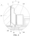
FIG. 4 is an enlarged view at A inFIG. 3 . - 100, battery module; 200, liquid cooling plate; 300, box; 310, cross beam; 10, battery module outer frame; 1, side plate; 11 side plate body; 12, hanger; 2, end plate; 3, hot-pressed insulating film; 4, middle plate; 5, upper cover; 20, module body; 30, thermally conductive structural adhesive; 40, limiting member; 50, connecting structural adhesive.
- As shown in
FIG. 1 , the embodiments provide a battery pack that may be applied to a new energy vehicle, but not limited thereto, and may also be applied to other electrical devices. Specifically, the battery pack includes abox 300 and a plurality ofbattery modules 100, and the plurality ofbattery modules 100 are integrated in thebox 300 by CTP. - In order to ensure the normal operation of the
battery module 100, the battery pack disclosed in the embodiments further includes aliquid cooling plate 200. Theliquid cooling plate 200 is disposed at a bottom of thebox 300. A bottom of thebattery module 100 is disposed on theliquid cooling plate 200. Theliquid cooling plate 200 dissipates and cools thebattery module 100 by liquid cooling to ensure the normal operation of thebattery module 100. - As shown in
FIG. 2 , the battery module includes a module body and a battery moduleouter frame 10. Themodule body 20 is fixed in the battery moduleouter frame 10. It should be noted that in the embodiments, themodule body 20 includes a plurality of cells arranged at intervals, and twomodule bodies 20 are arranged at intervals in each battery moduleouter frame 10 in the left-right direction, so that thebattery module 100 has a double-row structure. In other embodiments,more module bodies 20 may also be installed in each battery moduleouter frame 10. - Specifically, as shown in
FIG. 2 , the battery moduleouter frame 10 includes aside plate 1 and anend plate 2. Theside plate 1 extends in a first direction (the front-rear direction in the figure). Theend plate 2 extends in a second direction (the left-right direction in the figure). Theend plate 2 is connected to theside plate 1. Preferably, in the embodiments, twoside plates 1 are provided at intervals in the left-right direction, and twoend plates 2 are provided at intervals in the front-rear direction. The twoside plates 1 and the twoend plates 2 are jointly enclosed to form a mounting frame, and the plurality ofmodule bodies 20 are fixed in the mounting frame. - In the related art, when manufacturing the side plate, it is usually necessary to punch out the side plate body and the hanger by using the side plate body stamping die and the hanger stamping die, respectively, and then the hanger is welded to the side plate body. The manufacturing process of the side plate is complicated, and the deformation between the side plate body and the hanger is easy to occur. In order to facilitate the processing of the side plate, the side plate body is usually bent to form hanger, but this processing method may not meet the processing of complex hanger structures, and also reduces the structural strength of the side plate.
- In order to solve the above problems, as shown in
FIG. 2 , theside plate 1 provided in the embodiments includes aside plate body 11 and ahanger 12. Theside plate body 11 and thehanger 12 are integrally roll formed, and theend plate 2 and theside plate body 11 are connected by laser welding. Since theside plate body 11 and thehanger 12 are integrally roll formed, the processing of thecomplex hanger 12 is satisfied, and the structural strength of thewhole side plate 1 is improved. The processing is convenient, and the manufacturing cost of the side plate is reduced. Theend plate 2 and theside plate body 11 may be connected by laser welding without laser filling welding, so that the welding process between theend plate 2 and theside plate body 11 is simple, and the manufacturing cost of the whole battery moduleouter frame 10 is reduced. - It should be noted that, in the embodiments, the
side plate 1 is made of a 5-series aluminum alloy material, and theend plate 2 is made of a 6-series aluminum alloy material, thereby ensuring that theside plate body 11 and theend plate 2 may be connected only by laser welding. In addition, the 5-series aluminum alloy has the advantage of being lightweight. - Further, as shown in
FIG. 2 , the battery moduleouter frame 10 further includes amiddle plate 4 extending in the front-rear direction. Themiddle plate 4 is sandwiched between twoadjacent module bodies 20. Themiddle plate 4 and theend plate 2 are connected by laser welding. Since themiddle plate 4 and theend plate 2 are connected also by laser welding, the welding mode of the entire battery moduleouter frame 10 is unified, and it is more convenient to process and manufacture the entire battery moduleouter frame 10. - In addition, as shown in
FIG. 2 , the battery moduleouter frame 10 further includes a hot-pressedinsulating film 3. The hot-pressedinsulating film 3 is hot-pressed onto theside plate body 11, thereby ensuring the firmness of hot-pressing between the hot-pressedinsulating film 3 and theside plate body 11, and ensuring the reliability of insulating by the hot-pressedinsulating film 3. - Further, in the embodiments, the battery module
outer frame 10 further includes anupper cover 5. Theupper cover 5 is buckled on the mounting frame and located on a top of themodule body 20, so as to better realize the protection of themodule body 20. - As shown in
FIGS. 3 and4 , thebattery module 100 provided by the embodiments further includes a thermally conductivestructural adhesive 30. The bottom of themodule body 20 is bonded to theliquid cooling plate 200 through the thermally conductivestructural adhesive 30, which not only ensures the effect of heat dissipation and cooling of themodule body 20 by theliquid cooling plate 200, but also ensures the stability and reliability of the connection between themodule body 20 and theliquid cooling plate 200. - Preferably, as shown in
FIGS. 3 and4 , thebattery module 100 further includes a connectingstructural adhesive 50. A side portion of thehanger 12 is bonded to thecross beam 310 of thebox 300 through the connectingstructural adhesive 50, thereby improving the connection stiffness between thehanger 12 and thecross beam 310, reducing the mechanical connection, thereby improving the specific energy of the entire battery pack and reducing the cost. - In the embodiments, as shown in
FIG. 4 , thebattery module 100 further includes a limitingmember 40 disposed at the bottom of theside plate 1. The limitingmember 40 is used to limit the thickness of the thermally conductive structural adhesive 30 to ensure that the thickness of the thermally conductivestructural adhesive 30 is within a required range, thereby ensuring the thermal conductivity of the thermally conductivestructural adhesive 30. - Specifically, the limiting
member 40 is a foam. The foam is bonded to the bottom of theside plate 1, and the bottom of the foam is in contact with theliquid cooling plate 200, so that the thickness of the thermally conductivestructural adhesive 30 is limited by the thickness of the foam. In addition, the foam also plays a cushioning and protective role for theside plate 1.
Claims (11)
- A battery module outer frame, comprising:a side plate (1) extending in a first direction, wherein the side plate (1) comprises a side plate body (11) and a hanger (12), and the side plate body (11) and the hanger (12) are integrally roll formed; andan end plate (2) extending in a second direction, wherein the end plate (2) is connected to the side plate body (11) by laser welding, and the first direction is perpendicular to the second direction.
- The battery module outer frame of claim 1, further comprising:
a hot-pressed insulating film (3) hot-pressed onto the side plate body (11). - The battery module outer frame of claim 1, wherein two side plates (1) are provided at intervals in the second direction, two end plates (2) are provided at intervals in the first direction, and the two side plates (1) and the two end plates (2) are jointly enclosed to form a mounting frame configured to fix a plurality of module bodies (20).
- The battery module outer frame of claim 3, further comprising:
a middle plate (4) extending along the first direction, wherein the middle plate (4) is configured to be sandwiched between adj acent two of the module bodies (20), and the middle plate (4) is connected to the end plate (2) by laser welding. - The battery module outer frame of any one of claims 1 to 4, wherein the side plate (1) is made of a 5-series aluminum alloy material, and the end plate (2) is made of a 6-series aluminum alloy material.
- A battery module, wherein the battery module comprises a module body (20) and the battery module outer frame of any one of claims 1 to 5, and the module body (20) is fixed in the battery module outer frame.
- The battery module of claim 6, further comprising:
a thermally conductive structural adhesive (30), wherein a bottom of the module body (20) is bonded to a liquid cooling plate (200) through the thermally conductive structural adhesive (30). - The battery module of claim 7, wherein the battery module further comprises a limiting member (40) disposed at a bottom of the side plate (1), and the limiting member (40) is configured to limit a thickness of the thermally conductive structural adhesive (30).
- The battery module of claim 8, wherein the limiting member (40) is a foam, the foam is bonded to a bottom of the side plate (1), and a bottom of the foam is in contact with the liquid cooling plate (200).
- The battery module of claim 6, further comprising:
a connecting structural adhesive (50), wherein a side portion of the hanger (12) is bonded to a cross beam (310) of a box (300) through the connecting structural adhesive (50). - A battery pack, wherein the battery pack comprises a box (300) and the battery module of any one of claims 6 to 10, and the battery module is fixed in the box (300).
Applications Claiming Priority (2)
| Application Number | Priority Date | Filing Date | Title |
|---|---|---|---|
| CN202321659485.6U CN219959284U (en) | 2023-06-28 | 2023-06-28 | A battery module outer frame, battery module and battery pack |
| PCT/CN2024/077714 WO2025001186A1 (en) | 2023-06-28 | 2024-02-20 | External battery module frame, battery module, and battery pack |
Publications (1)
| Publication Number | Publication Date |
|---|---|
| EP4521532A1 true EP4521532A1 (en) | 2025-03-12 |
Family
ID=88546990
Family Applications (1)
| Application Number | Title | Priority Date | Filing Date |
|---|---|---|---|
| EP24813088.2A Pending EP4521532A1 (en) | 2023-06-28 | 2024-02-20 | External battery module frame, battery module, and battery pack |
Country Status (6)
| Country | Link |
|---|---|
| US (1) | US20250096384A1 (en) |
| EP (1) | EP4521532A1 (en) |
| JP (1) | JP2025524272A (en) |
| KR (1) | KR20250003638A (en) |
| CN (1) | CN219959284U (en) |
| WO (1) | WO2025001186A1 (en) |
Families Citing this family (1)
| Publication number | Priority date | Publication date | Assignee | Title |
|---|---|---|---|---|
| CN219959284U (en) * | 2023-06-28 | 2023-11-03 | 惠州亿纬锂能股份有限公司 | A battery module outer frame, battery module and battery pack |
Family Cites Families (9)
| Publication number | Priority date | Publication date | Assignee | Title |
|---|---|---|---|---|
| JPH07186734A (en) * | 1993-12-27 | 1995-07-25 | Honda Motor Co Ltd | Electric vehicle battery box structure |
| KR101669114B1 (en) * | 2012-04-30 | 2016-10-25 | 삼성에스디아이 주식회사 | Battery pack having modulization structure |
| KR102485011B1 (en) * | 2020-10-12 | 2023-01-04 | 주식회사 포스코 | Side frame for battery case |
| CN115483468A (en) * | 2021-05-31 | 2022-12-16 | 威马智慧出行科技(上海)股份有限公司 | Battery module and manufacturing method thereof |
| CN116325293A (en) * | 2021-07-12 | 2023-06-23 | 株式会社 Lg新能源 | Battery module and battery pack including the battery module |
| CN217589091U (en) * | 2021-12-22 | 2022-10-14 | 湖北亿纬动力有限公司 | Battery module structure |
| CN217589294U (en) * | 2022-05-18 | 2022-10-14 | 湖北亿纬动力有限公司 | Outer frame and battery module |
| CN115714227A (en) * | 2022-11-15 | 2023-02-24 | 中创新航科技股份有限公司 | Battery module and battery pack |
| CN219959284U (en) * | 2023-06-28 | 2023-11-03 | 惠州亿纬锂能股份有限公司 | A battery module outer frame, battery module and battery pack |
-
2023
- 2023-06-28 CN CN202321659485.6U patent/CN219959284U/en active Active
-
2024
- 2024-02-20 WO PCT/CN2024/077714 patent/WO2025001186A1/en not_active Ceased
- 2024-02-20 KR KR1020247035776A patent/KR20250003638A/en active Pending
- 2024-02-20 EP EP24813088.2A patent/EP4521532A1/en active Pending
- 2024-02-20 JP JP2024564954A patent/JP2025524272A/en active Pending
- 2024-11-29 US US18/964,263 patent/US20250096384A1/en active Pending
Also Published As
| Publication number | Publication date |
|---|---|
| CN219959284U (en) | 2023-11-03 |
| JP2025524272A (en) | 2025-07-28 |
| US20250096384A1 (en) | 2025-03-20 |
| KR20250003638A (en) | 2025-01-07 |
| WO2025001186A1 (en) | 2025-01-02 |
Similar Documents
| Publication | Publication Date | Title |
|---|---|---|
| EP3930080A1 (en) | Battery module and battery pack including same | |
| JP2005285625A (en) | Battery frame and battery pack | |
| CN214280152U (en) | Battery module and energy storage device | |
| CN210040347U (en) | Battery module and power battery | |
| US20250096384A1 (en) | Battery module outer frame, battery module and battery pack | |
| CN115149187A (en) | A battery module and electronic device | |
| CN112117411A (en) | Sandwich structure bottom plate of power battery lower box body and power battery lower box body | |
| EP4465429B1 (en) | Battery module, and battery pack and vehicle including the same | |
| US20250023168A1 (en) | Battery and electric-consuming device | |
| JP2006318871A (en) | Storage structure for battery cell | |
| JP2015201289A (en) | Power storage element | |
| KR20190000094U (en) | Photovoltaic power generation car roof | |
| JP2022545032A (en) | Battery packs and devices containing them | |
| KR20220018706A (en) | Battery module and battery pack including the same | |
| KR20220115390A (en) | Battery Module, Battery Pack, and Vehicle | |
| CN216488330U (en) | Battery module | |
| CN222749636U (en) | Lower shell structure of battery pack and battery pack | |
| CN212934716U (en) | A power battery module structure | |
| CN220692478U (en) | Busbars, battery modules and battery packs | |
| EP4075583A1 (en) | Power storage device | |
| CN114566769B (en) | Electrochemical devices, battery modules and electrical devices | |
| CN211828971U (en) | battery pack | |
| CN212209588U (en) | The battery module of the battery pack and the battery pack | |
| CN214797574U (en) | Energy storage battery structure | |
| US20250329856A1 (en) | Power storage device |
Legal Events
| Date | Code | Title | Description |
|---|---|---|---|
| STAA | Information on the status of an ep patent application or granted ep patent |
Free format text: STATUS: UNKNOWN |
|
| STAA | Information on the status of an ep patent application or granted ep patent |
Free format text: STATUS: THE INTERNATIONAL PUBLICATION HAS BEEN MADE |
|
| PUAI | Public reference made under article 153(3) epc to a published international application that has entered the european phase |
Free format text: ORIGINAL CODE: 0009012 |
|
| STAA | Information on the status of an ep patent application or granted ep patent |
Free format text: STATUS: REQUEST FOR EXAMINATION WAS MADE |
|
| 17P | Request for examination filed |
Effective date: 20241205 |
|
| AK | Designated contracting states |
Kind code of ref document: A1 Designated state(s): AL AT BE BG CH CY CZ DE DK EE ES FI FR GB GR HR HU IE IS IT LI LT LU LV MC ME MK MT NL NO PL PT RO RS SE SI SK SM TR |