EP4521512A1 - Battery system including cooling plate and method of controlling the same - Google Patents
Battery system including cooling plate and method of controlling the same Download PDFInfo
- Publication number
- EP4521512A1 EP4521512A1 EP24194376.0A EP24194376A EP4521512A1 EP 4521512 A1 EP4521512 A1 EP 4521512A1 EP 24194376 A EP24194376 A EP 24194376A EP 4521512 A1 EP4521512 A1 EP 4521512A1
- Authority
- EP
- European Patent Office
- Prior art keywords
- circulation pump
- battery
- temperature
- processor
- battery system
- Prior art date
- Legal status (The legal status is an assumption and is not a legal conclusion. Google has not performed a legal analysis and makes no representation as to the accuracy of the status listed.)
- Granted
Links
Images




Classifications
-
- H—ELECTRICITY
- H01—ELECTRIC ELEMENTS
- H01M—PROCESSES OR MEANS, e.g. BATTERIES, FOR THE DIRECT CONVERSION OF CHEMICAL ENERGY INTO ELECTRICAL ENERGY
- H01M10/00—Secondary cells; Manufacture thereof
- H01M10/60—Heating or cooling; Temperature control
- H01M10/63—Control systems
- H01M10/637—Control systems characterised by the use of reversible temperature-sensitive devices, e.g. NTC, PTC or bimetal devices; characterised by control of the internal current flowing through the cells, e.g. by switching
-
- H—ELECTRICITY
- H01—ELECTRIC ELEMENTS
- H01M—PROCESSES OR MEANS, e.g. BATTERIES, FOR THE DIRECT CONVERSION OF CHEMICAL ENERGY INTO ELECTRICAL ENERGY
- H01M10/00—Secondary cells; Manufacture thereof
- H01M10/60—Heating or cooling; Temperature control
- H01M10/61—Types of temperature control
- H01M10/613—Cooling or keeping cold
-
- A—HUMAN NECESSITIES
- A62—LIFE-SAVING; FIRE-FIGHTING
- A62C—FIRE-FIGHTING
- A62C3/00—Fire prevention, containment or extinguishing specially adapted for particular objects or places
- A62C3/16—Fire prevention, containment or extinguishing specially adapted for particular objects or places in electrical installations, e.g. cableways
-
- A—HUMAN NECESSITIES
- A62—LIFE-SAVING; FIRE-FIGHTING
- A62C—FIRE-FIGHTING
- A62C35/00—Permanently-installed equipment
- A62C35/02—Permanently-installed equipment with containers for delivering the extinguishing substance
- A62C35/10—Containers destroyed or opened by flames or heat
-
- H—ELECTRICITY
- H01—ELECTRIC ELEMENTS
- H01M—PROCESSES OR MEANS, e.g. BATTERIES, FOR THE DIRECT CONVERSION OF CHEMICAL ENERGY INTO ELECTRICAL ENERGY
- H01M10/00—Secondary cells; Manufacture thereof
- H01M10/42—Methods or arrangements for servicing or maintenance of secondary cells or secondary half-cells
- H01M10/48—Accumulators combined with arrangements for measuring, testing or indicating the condition of cells, e.g. the level or density of the electrolyte
- H01M10/482—Accumulators combined with arrangements for measuring, testing or indicating the condition of cells, e.g. the level or density of the electrolyte for several batteries or cells simultaneously or sequentially
-
- H—ELECTRICITY
- H01—ELECTRIC ELEMENTS
- H01M—PROCESSES OR MEANS, e.g. BATTERIES, FOR THE DIRECT CONVERSION OF CHEMICAL ENERGY INTO ELECTRICAL ENERGY
- H01M10/00—Secondary cells; Manufacture thereof
- H01M10/42—Methods or arrangements for servicing or maintenance of secondary cells or secondary half-cells
- H01M10/48—Accumulators combined with arrangements for measuring, testing or indicating the condition of cells, e.g. the level or density of the electrolyte
- H01M10/486—Accumulators combined with arrangements for measuring, testing or indicating the condition of cells, e.g. the level or density of the electrolyte for measuring temperature
-
- H—ELECTRICITY
- H01—ELECTRIC ELEMENTS
- H01M—PROCESSES OR MEANS, e.g. BATTERIES, FOR THE DIRECT CONVERSION OF CHEMICAL ENERGY INTO ELECTRICAL ENERGY
- H01M10/00—Secondary cells; Manufacture thereof
- H01M10/60—Heating or cooling; Temperature control
- H01M10/62—Heating or cooling; Temperature control specially adapted for specific applications
- H01M10/625—Vehicles
-
- H—ELECTRICITY
- H01—ELECTRIC ELEMENTS
- H01M—PROCESSES OR MEANS, e.g. BATTERIES, FOR THE DIRECT CONVERSION OF CHEMICAL ENERGY INTO ELECTRICAL ENERGY
- H01M10/00—Secondary cells; Manufacture thereof
- H01M10/60—Heating or cooling; Temperature control
- H01M10/63—Control systems
-
- H—ELECTRICITY
- H01—ELECTRIC ELEMENTS
- H01M—PROCESSES OR MEANS, e.g. BATTERIES, FOR THE DIRECT CONVERSION OF CHEMICAL ENERGY INTO ELECTRICAL ENERGY
- H01M10/00—Secondary cells; Manufacture thereof
- H01M10/60—Heating or cooling; Temperature control
- H01M10/63—Control systems
- H01M10/633—Control systems characterised by algorithms, flow charts, software details or the like
-
- H—ELECTRICITY
- H01—ELECTRIC ELEMENTS
- H01M—PROCESSES OR MEANS, e.g. BATTERIES, FOR THE DIRECT CONVERSION OF CHEMICAL ENERGY INTO ELECTRICAL ENERGY
- H01M10/00—Secondary cells; Manufacture thereof
- H01M10/60—Heating or cooling; Temperature control
- H01M10/63—Control systems
- H01M10/635—Control systems based on ambient temperature
-
- H—ELECTRICITY
- H01—ELECTRIC ELEMENTS
- H01M—PROCESSES OR MEANS, e.g. BATTERIES, FOR THE DIRECT CONVERSION OF CHEMICAL ENERGY INTO ELECTRICAL ENERGY
- H01M10/00—Secondary cells; Manufacture thereof
- H01M10/60—Heating or cooling; Temperature control
- H01M10/65—Means for temperature control structurally associated with the cells
- H01M10/655—Solid structures for heat exchange or heat conduction
- H01M10/6554—Rods or plates
-
- H—ELECTRICITY
- H01—ELECTRIC ELEMENTS
- H01M—PROCESSES OR MEANS, e.g. BATTERIES, FOR THE DIRECT CONVERSION OF CHEMICAL ENERGY INTO ELECTRICAL ENERGY
- H01M10/00—Secondary cells; Manufacture thereof
- H01M10/60—Heating or cooling; Temperature control
- H01M10/65—Means for temperature control structurally associated with the cells
- H01M10/655—Solid structures for heat exchange or heat conduction
- H01M10/6556—Solid parts with flow channel passages or pipes for heat exchange
-
- H—ELECTRICITY
- H01—ELECTRIC ELEMENTS
- H01M—PROCESSES OR MEANS, e.g. BATTERIES, FOR THE DIRECT CONVERSION OF CHEMICAL ENERGY INTO ELECTRICAL ENERGY
- H01M10/00—Secondary cells; Manufacture thereof
- H01M10/60—Heating or cooling; Temperature control
- H01M10/65—Means for temperature control structurally associated with the cells
- H01M10/656—Means for temperature control structurally associated with the cells characterised by the type of heat-exchange fluid
- H01M10/6567—Liquids
-
- H—ELECTRICITY
- H01—ELECTRIC ELEMENTS
- H01M—PROCESSES OR MEANS, e.g. BATTERIES, FOR THE DIRECT CONVERSION OF CHEMICAL ENERGY INTO ELECTRICAL ENERGY
- H01M10/00—Secondary cells; Manufacture thereof
- H01M10/60—Heating or cooling; Temperature control
- H01M10/65—Means for temperature control structurally associated with the cells
- H01M10/656—Means for temperature control structurally associated with the cells characterised by the type of heat-exchange fluid
- H01M10/6567—Liquids
- H01M10/6568—Liquids characterised by flow circuits, e.g. loops, located externally to the cells or cell casings
-
- H—ELECTRICITY
- H01—ELECTRIC ELEMENTS
- H01M—PROCESSES OR MEANS, e.g. BATTERIES, FOR THE DIRECT CONVERSION OF CHEMICAL ENERGY INTO ELECTRICAL ENERGY
- H01M50/00—Constructional details or processes of manufacture of the non-active parts of electrochemical cells other than fuel cells, e.g. hybrid cells
- H01M50/20—Mountings; Secondary casings or frames; Racks, modules or packs; Suspension devices; Shock absorbers; Transport or carrying devices; Holders
- H01M50/204—Racks, modules or packs for multiple batteries or multiple cells
-
- H—ELECTRICITY
- H01—ELECTRIC ELEMENTS
- H01M—PROCESSES OR MEANS, e.g. BATTERIES, FOR THE DIRECT CONVERSION OF CHEMICAL ENERGY INTO ELECTRICAL ENERGY
- H01M50/00—Constructional details or processes of manufacture of the non-active parts of electrochemical cells other than fuel cells, e.g. hybrid cells
- H01M50/20—Mountings; Secondary casings or frames; Racks, modules or packs; Suspension devices; Shock absorbers; Transport or carrying devices; Holders
- H01M50/204—Racks, modules or packs for multiple batteries or multiple cells
- H01M50/207—Racks, modules or packs for multiple batteries or multiple cells characterised by their shape
- H01M50/211—Racks, modules or packs for multiple batteries or multiple cells characterised by their shape adapted for pouch cells
-
- H—ELECTRICITY
- H01—ELECTRIC ELEMENTS
- H01M—PROCESSES OR MEANS, e.g. BATTERIES, FOR THE DIRECT CONVERSION OF CHEMICAL ENERGY INTO ELECTRICAL ENERGY
- H01M50/00—Constructional details or processes of manufacture of the non-active parts of electrochemical cells other than fuel cells, e.g. hybrid cells
- H01M50/20—Mountings; Secondary casings or frames; Racks, modules or packs; Suspension devices; Shock absorbers; Transport or carrying devices; Holders
- H01M50/258—Modular batteries; Casings provided with means for assembling
-
- H—ELECTRICITY
- H01—ELECTRIC ELEMENTS
- H01M—PROCESSES OR MEANS, e.g. BATTERIES, FOR THE DIRECT CONVERSION OF CHEMICAL ENERGY INTO ELECTRICAL ENERGY
- H01M10/00—Secondary cells; Manufacture thereof
- H01M10/60—Heating or cooling; Temperature control
- H01M10/64—Heating or cooling; Temperature control characterised by the shape of the cells
- H01M10/647—Prismatic or flat cells, e.g. pouch cells
-
- H—ELECTRICITY
- H01—ELECTRIC ELEMENTS
- H01M—PROCESSES OR MEANS, e.g. BATTERIES, FOR THE DIRECT CONVERSION OF CHEMICAL ENERGY INTO ELECTRICAL ENERGY
- H01M2200/00—Safety devices for primary or secondary batteries
- H01M2200/10—Temperature sensitive devices
-
- Y—GENERAL TAGGING OF NEW TECHNOLOGICAL DEVELOPMENTS; GENERAL TAGGING OF CROSS-SECTIONAL TECHNOLOGIES SPANNING OVER SEVERAL SECTIONS OF THE IPC; TECHNICAL SUBJECTS COVERED BY FORMER USPC CROSS-REFERENCE ART COLLECTIONS [XRACs] AND DIGESTS
- Y02—TECHNOLOGIES OR APPLICATIONS FOR MITIGATION OR ADAPTATION AGAINST CLIMATE CHANGE
- Y02E—REDUCTION OF GREENHOUSE GAS [GHG] EMISSIONS, RELATED TO ENERGY GENERATION, TRANSMISSION OR DISTRIBUTION
- Y02E60/00—Enabling technologies; Technologies with a potential or indirect contribution to GHG emissions mitigation
- Y02E60/10—Energy storage using batteries
Definitions
- Embodiments of the disclosed technology relate to a battery system and a method of controlling the same.
- secondary batteries may be charged and discharged, and thus, may be applied to various fields such as digital cameras, mobile phones, laptops, hybrid cars, electric cars, and energy storage systems (ESS).
- Examples of secondary batteries may include, among others, lithium ion batteries, nickel-cadmium batteries, nickel-metal hydride batteries, and nickel-hydrogen batteries.
- the disclosed technology may be implemented in some embodiments to provide a battery system including a battery pack capable of providing refrigerant to a battery module in which a fire occurs.
- a battery system including a cooling plate based on an example embodiment and a method of controlling may be widely applied in green technology fields such as electric vehicles, battery charging stations, and solar power generation and wind power generation using other batteries.
- a battery system including a cooling plate based on an example embodiment and a method of controlling the same may be used in eco-friendly electric vehicles, hybrid vehicles, and others to prevent climate change by suppressing air pollution and greenhouse gas emissions.
- a battery system includes a battery pack including a pack frame, a plurality of battery modules disposed within the pack frame, and a cooling plate covering the plurality of battery modules and including an accommodation space for accommodating a refrigerant, a cooling passage connected to the cooling plate, a circulation pump connected to the cooling passage and configured to circulate the refrigerant within the cooling passage and the cooling plate, a pressure sensor disposed within the cooling passage and configured to detect a pressure in the cooling passage, a plurality of temperature sensors disposed on the plurality of battery modules and configured to detect a temperature of the plurality of battery modules, and a processor electrically connected to the plurality of temperature sensors and the pressure sensor.
- the processor is configured to adjust an output of the circulation pump based on at least one of a temperature detected by one or more of the plurality of temperature sensors and pressure detected by the pressure sensor.
- the pack frame may include a compartment accommodating at least one of the plurality of battery modules.
- At least a portion of the cooling plate may be configured to melt based on a fire occurring in at least some of the plurality of battery modules. At least a portion of the refrigerant may be configured to flow into a space of a compartment in which a battery module in which the fire occurred among the plurality of battery modules is located through a melted portion of the cooling plate.
- the processor may be configured to stop an operation of the circulation pump when a temperature detected by the plurality of temperature sensors exceeds a predetermined temperature.
- the processor may be configured to stop an operation the circulation pump when a difference between temperature values detected by the plurality of temperature sensors is equal to or greater than a predetermined magnitude.
- the processor may be configured to reduce the output of the circulation pump when a temperature detected by the plurality of temperature sensors exceeds a predetermined temperature.
- the processor may be configured to increase the output of the circulation pump when the pressure detected by the pressure sensor is less than a predetermined pressure.
- the processor may be configured to reduce the output of the circulation pump when a difference between temperature values detected by the plurality of temperature sensors is equal to or greater than a predetermined magnitude.
- the processor may be configured to increase the output of the circulation pump when the pressure detected by the pressure sensor is less than a predetermined pressure.
- the battery system may further include a reserve tank connected to the cooling passage and accommodating at least a portion of the refrigerant.
- a size of a volume of the accommodation space of the cooling plate, the cooling passage, and the reserve tank may be greater than or equal to a volume inside a compartment of the pack frame.
- the battery system may include a cooling device connected to the cooling passage and configured to cool the refrigerant.
- the processor may be configured to activate or drive the circulation pump when the pressure detected by the pressure sensor is less than a predetermined pressure.
- the processor may drive the circulation pump for a predetermined time interval after a predetermined time passes after an operation of the circulation pump is stopped based on a temperature detected by the plurality of temperature sensors.
- the processor may be configured to activate or drive the circulation pump for a predetermined time interval based on the temperature detected by the temperature sensor after stopping operation of the circulation pump based on a temperature detected by the plurality of temperature sensors.
- the processor may be configured to activate or drive the circulation pump for a predetermined time interval based on the pressure detected by the pressure sensor after stopping operation of the circulation pump based on a temperature detected by the plurality of temperature sensors.
- the cooling plate may include aluminum.
- a method of controlling a battery system includes a temperature detection operation of detecting a temperature of a battery module using a temperature sensor, a temperature comparison operation of comparing the temperature detected by the temperature sensor with a predetermined temperature, a circulation pump driving stop operation of stopping driving a circulation pump when the detected temperature exceeds the predetermined temperature, a pressure comparison operation of comparing a pressure detected using a pressure sensor with a predetermined pressure, and a circulation pump driving operation of driving the circulation pump when the detected pressure is less than the predetermined pressure.
- the method of controlling a battery system may further include a circulation pump temporary driving operation of temporarily driving the circulation pump after driving of the circulation pump is stopped based on the temperature detected by the temperature sensor.
- the circulation pump temporary driving operation may be configured to operate the circulation pump for a predetermined time period after a predetermined time from the circulation pump driving stop operation.
- the circulation pump driving operation may be configured to be performed when the pressure detected by the pressure sensor is less than a predetermined value, after the circulation pump temporary driving operation.
- a battery system includes a battery pack including a pack frame, a plurality of battery modules disposed within the pack frame, and a cooling plate covering the plurality of battery modules and including an accommodation space for accommodating a refrigerant, a cooling passage connected to the cooling plate, a circulation pump connected to the cooling passage and configured to circulate the refrigerant within the cooling passage and the cooling plate, a pressure sensor disposed within the cooling passage, a plurality of temperature sensors disposed on the plurality of battery modules, and a processor electrically connected to the plurality of temperature sensors and the pressure sensor.
- the processor is configured to stop driving the circulation pump based on a temperature detected by at least some of the plurality of temperature sensors.
- the processor is configured to drive the circulation pump based on a pressure detected by the pressure sensor.
- the disclosed technology may be implemented in some embodiments to provide a battery system including a cooling plate and a method of controlling the same.
- Secondary batteries may be manufactured to include flexible pouch-type battery cells or rigid prismatic or cylindrical can-type battery cells.
- a plurality of battery cells may be formed as a stacked cell assembly.
- the cell assembly may be disposed inside a case to form a battery module, and a plurality of battery modules may be disposed inside a pack frame to form a battery pack.
- Battery packs may be used in various systems such as vehicles or energy storage systems.
- Electric vehicles, hybrid vehicles, or energy storage systems powered by an electrical energy source may include a plurality of battery cells. Therefore, if a fire starts in one battery module, it can spread to adjacent battery modules or other components. Refrigerants can be used to suppress fires occurring in battery modules. However, the amount of refrigerant that can be accommodated in a vehicle may be limited.
- the disclosed technology can be implemented in some embodiments to address these issues by providing a battery system including a battery pack capable of delaying heat propagation between battery modules.
- the disclosed technology may be implemented in some embodiments to address these issues by providing a battery system including a battery pack capable of providing refrigerant to a battery module in which a fire occurs.
- FIG. 1 is a perspective view of a battery cell based on an example embodiment.
- the sealing portion 115 may be formed by joining at least portions of the circumference of the pouch 110.
- the sealing portion 115 is formed in the form of a flange extending outwardly from the electrode accommodating portion 111 formed in the shape of a container, and may be disposed along at least a portion of the exterior of the electrode accommodating portion 111.
- the sealing portion 115 may include a first sealing portion 115a where the electrode tab 130 is located and a second sealing portion 115b where the electrode tab 130 is not located. A portion of the electrode tab 130 may be led out or exposed to the outside of the pouch 110.
- the electrode tab 130 may be covered by an insulating film 140.
- the insulating film 140 is formed of a thinner film material than a material of the electrode tab 130 and may be attached to both sides of the electrode tab 130.
- the electrode tabs 130 may be disposed on both sides of the battery cell 100 in the longitudinal direction (e.g., Y-axis direction) to face opposite directions.
- the electrode tab 130 may include a first electrode tab 130a (e.g., positive electrode tab) of a first polarity (e.g., positive electrode) facing one side of the battery cell 100 in the longitudinal direction, and a second electrode tab 130b (e.g., negative electrode tab) of a second polarity (e.g., negative electrode) facing the other side of the battery cell 100 in the longitudinal direction.
- first electrode tab 130a e.g., positive electrode tab
- a second electrode tab 130b e.g., negative electrode tab
- the sealing portion 115 may include two first sealing portions 115a on which the electrode tabs 130 are disposed and one second sealing portion 115b on which the electrode tabs 130 are not disposed.
- the electrode tab 130 may be referred to as an electrode lead.
- the electrode tab 130 may include a first electrode tab 130a facing in the first direction and a second electrode tab 130b located in the opposite direction (e.g., the second direction) of the first electrode tab 130a with respect to the electrode assembly 120.
- the electrode tabs 130 are illustrated as facing in opposite directions on both sides of the battery cell 100 in the longitudinal direction (e.g., the first direction such as Y-axis direction), but the structure of the electrode tab 130 is not limited thereto.
- two electrode tabs 130 may be arranged substantially in parallel along the longitudinal direction (e.g., Y-axis direction) of the battery cell 100.
- the sealing portions 115 may be formed to be folded at least once. By folding at least a portion of the sealing portion 115, the bonding reliability of the sealing portion 115 may be improved and the area of the sealing portion 115 may be significantly reduced.
- the sealing portions 115 based on an example embodiment, the second sealing portion 115b on which the electrode tab 130 is not disposed may be folded twice and then fixed by an adhesive member (not illustrated). The angle at which the second sealing portion 115b is bent or the number of times the second sealing portion 115b is bent may be changed. For example, in an example embodiment, the second sealing portion 115b may be folded by 90° with respect to the first sealing portion 115a (not illustrated).
- the pouch 110 is not limited to a structure in which the sealing portion 115 is formed on three sides by folding one sheet of exterior material as illustrated in FIG. 1 .
- the electrode assembly 120 may be manufactured using a variety of methods.
- an electrode assembly may be formed by repeatedly disposing a positive electrode, a negative electrode, and a separator.
- the electrode assembly may be a winding type, a stacking type, a zigzag folding type, or a stack-folding type electrode assembly.
- the battery cell 100 is illustrated as a pouch-type battery cell including the pouch 110 by way of example.
- the battery cell 100 may a shape that is different from the pouch-type battery cell.
- the battery cell 100 may be a cylindrical battery cell or a prismatic battery cell.
- FIG. 2 is a perspective view of a battery module based on an example embodiment.
- a battery module 200 may include a module case 210 that accommodates a plurality of battery cells (e.g., battery cells 100 of FIG. 1 ), and a busbar assembly 220.
- a module case 210 that accommodates a plurality of battery cells (e.g., battery cells 100 of FIG. 1 ), and a busbar assembly 220.
- the battery module 200 may include a cell assembly (not illustrated) including the plurality of battery cells 100.
- the cell assembly may be referred to as a cell stack.
- the module case 210 forms at least a portion of the exterior of the battery module 200 and may have an accommodation space for accommodating a plurality of battery cells 100.
- the module case 210 may include a cover 211 that covers the plurality of battery cells 100 and an accommodating portion 212 that surrounds the lower surface and side surfaces of the plurality of battery cells 100.
- the cover 211 may be referred to as an upper cover.
- the module case 210 may include an end plate 215 that covers some of the side surfaces of the plurality of battery cells 100.
- the end plate 215 may be connected to an end of the accommodating portion 212 in the longitudinal direction (e.g., Y-axis direction).
- the end plate 215 may cover a portion of the side of the cell assembly and at least a portion of the busbar assembly 220.
- the module case 210 may be formed of a material with high thermal conductivity, such as metal.
- the module case 210 may be formed of aluminum.
- the material of the module case 210 is not limited thereto.
- the module case 210 may be formed of polymer.
- the module case 210 may be referred to as a housing, a module housing, or a module case.
- the busbar assembly 220 may include an electrically conductive internal busbar electrically connected to the electrode tab (e.g., electrode tab 130 in FIG. 1 ) of the battery cell 100, and a busbar frame supporting the internal busbar.
- the busbar assembly 220 may include at least one terminal busbar for external electrical connection.
- the electrode tab 130 of the battery cell 100 may be electrically connected to the outside of the battery module 200 through the internal busbar and the terminal busbar.
- the terminal busbar of the busbar assembly 220 may be exposed to the outside of the module case 210 through a hole in the end plate 215.
- some parts are omitted or exaggerated in this document.
- FIG. 3 is a perspective view of a battery system based on an example embodiment.
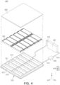
- FIG. 4 is an exploded perspective view of a battery system based on an example embodiment.
- a battery system 400 may include a battery pack 300, a cooling passage 410, a circulation pump 420, and a cooling device 430.
- the battery pack 300 may include at least one battery module (e.g., the battery module 200 of FIG. 2 ).
- the battery pack 300 may include a pack frame 310 that accommodates a plurality of battery modules 200.
- the pack frame 310 may include a compartment 311 that accommodates at least one of the plurality of battery modules 200.
- the pack frame 310 may include a partition wall 314 crossing at least some of the plurality of battery modules 200.
- the compartment 311 may be a space inside the battery pack 300 divided by the partition wall 314.
- at least some of the plurality of partition walls 314 may include venting holes for guiding the path of gas and/or flame generated in the battery module 200.
- the pack frame 310 may form at least a portion of the exterior of the battery pack 300.
- the pack frame 310 may include a bottom member 313 supporting the battery module 200 and a pack side wall 312 surrounding at least a portion of the battery module 200.
- the bottom member 313 may support the exterior material (e.g., the module case 210 of FIG. 2 ) of the battery module 200.
- the pack side wall 312 may be located between the bottom member 313 and a cooling plate 320.
- the battery pack 300 may include the cooling plate 320.
- the cooling plate 320 may cover a plurality of battery modules 200.
- the cooling plate 320 may surround the battery module 200 along with the pack side wall 312 and the bottom member 313.
- the cooling plate 320 may provide a path for refrigerant to flow.
- the cooling plate 320 may include an accommodation space 321 that accommodates refrigerant.
- the accommodation space 321 may be connected to the cooling passage 410.
- the cooling plate 320 may receive refrigerant through the cooling passage 410.
- the cooling plate 320 may be referred to as a heat sink.
- the cooling plate 320 may be in contact with or close to a portion (e.g., an upper portion) of the battery module 200.
- the battery module 200 may be heat dissipated or cooled by refrigerant flowing within the accommodation space 321 of the cooling plate 320.
- the refrigerant may be selectively applied as long as it is configured to extinguish a fire in the battery module 200.
- the refrigerant may include at least one of water, insulating coolant, foam extinguishing agent, powder extinguishing agent, or fire extinguishing gas.
- the cooling plate 320 may provide refrigerant to the battery module 200 in a thermal runaway situation of the battery module 200. For example, when the cooling plate 320 is melted, the refrigerant contained in the cooling plate 320 may be transferred to the battery module 200.
- the cooling plate 320 may be formed of a material that may melt in a thermal runaway situation of the battery module 200.
- the cooling plate 320 may include aluminum with a melting point temperature lower than the fire ignition temperature of the battery module 200.
- a portion of the cooling plate 320 located on the top of the battery module 200 where thermal runaway occurred is melted, and the refrigerant may be delivered to the compartment 311 where the battery module 200 where thermal runaway or fire has occurred is located by a melted portion of the cooling plate 320.
- the battery system 400 may include a battery pack 300 and components for cooling the battery pack 300.
- the battery system 400 may be a vehicle including the battery pack 300 or an energy storage system including the battery pack 300.
- the battery system 400 may include vehicle body. The vehicle body may accommodate the battery pack 300, the cooling passage 410, the circulation pump 420, the cooling device 430, a pressure sensor 440, a temperature sensor 450, and/or a processor 460.
- the battery system 400 may include a cooling passage 410.
- the cooling passage 410 may provide a path for refrigerant.
- the cooling passage 410 may provide a path for the refrigerant introduced into the cooling plate 320 of the battery pack 300 and/or the refrigerant discharged from the cooling plate 320.
- the cooling passage 410 may include a first flow path 411 connected to the circulation pump 420 and the battery pack 300, a second flow path 412 connected to the battery pack 300 and the cooling device 430, and a third flow path 413 connected to the cooling device 430 and the circulation pump 420.
- the structure in which the cooling passage 410 is connected to the cooling plate 320 is an example.
- the cooling passage 410 may be directly connected to the accommodation space 321 of the cooling plate 320.
- the pack frame 310 includes an empty space for the refrigerant to flow, and the cooling passage 410 may be connected to the accommodation space 321 of the cooling plate 320 through the pack frame 310.
- the battery system 400 may include the circulation pump 420.
- the circulation pump 420 may increase the pressure so that the refrigerant circulates in the cooling passage 410 and/or the cooling plate 320.
- the circulation pump 420 may be connected to the cooling passage 410.
- the battery system 400 may include the cooling device 430.
- the cooling device 430 is connected to the cooling passage 410 and may reduce the temperature of the refrigerant flowing through the cooling passage 410.
- the cooling device 430 may be a radiator or a heat dissipation device.
- FIG. 5 is a schematic diagram of a battery system based on an example embodiment.
- the battery system 400 may further include an auxiliary tank 480 spaced apart from the reserve tank 470.
- the auxiliary tank 480 may be connected to the cooling passage 410.
- the amount of refrigerant contained in the battery system 400 may be increased by the reserve tank 470 and the auxiliary tank 480, and cooling performance may be improved.
- the processor 460 may temporarily drive the circulation pump 420 after the circulation pump 420 is stopped based on the temperature detected by the temperature sensor 450. Due to the temporary operation of the circulation pump 420, the flow rate of the refrigerant in the cooling passage 410 and the cooling plate 320 may be improved. As the flow rate of the refrigerant is improved, at least a portion of the refrigerant may be sprayed to the outside of the cooling plate 320 through the melted portion of the cooling plate 320.
- Temporary operation of the circulation pump 420 may be performed based on time, pressure, and/or temperature.
- the processor 460 may operate the circulation pump 420 for a predetermined time period after a predetermined time from when the operation of the circulation pump 420 is stopped based on the temperature detected by the temperature sensor 450.
- the processor 460 may detect the pressure of the cooling passage 410 using the pressure sensor 440. When the pressure of the cooling passage 410 is less than a predetermined value, the processor 460 may operate the circulation pump 420. When the pressure of the cooling passage 410 is greater than or equal to a predetermined value, the processor 460 may maintain the circulation pump 420 in a stopped state.
- the method 500 of controlling a battery system in FIG. 6 may be a method of controlling the battery system 400 of FIGS. 3 to 5 .
- the pressure comparison operation 540 may be an operation in which the processor 460 compares the pressure detected by the pressure sensor 440 with a predetermined pressure.
- the processor 460 may compare the pressure sensed by the pressure sensor 440 with a predetermined pressure stored in memory (not illustrated).
- the pressure comparison operation 540 may be performed after or substantially simultaneously with the pressure detection operation of detecting the pressure of the cooling passage 410 using the pressure sensor 440.
- the pressure comparison operation 540 may be performed after the circulation pump driving stop operation 530.
- the circulation pump driving operation 550 may be an operation of operating the circulation pump 420 when the pressure detected by the pressure sensor 440 is less than a predetermined pressure. For example, when the pressure detected by the pressure sensor 440 is less than a predetermined pressure, the processor 460 determines that the refrigerant has leaked through the melted portion of the cooling plate 320, and may generate a signal to operate the circulation pump 420 for circulation of the refrigerant. By operating the circulation pump 420, the refrigerant may be delivered to the battery module 200 where a fire occurred through the melted portion of the cooling plate 320. At least a portion of the compartment (e.g., the compartment 311 in FIG. 4 ) where the battery module 200 where the ignition occurred is located is filled with refrigerant, and the battery module 200 in which ignition has occurred may be extinguished and/or cooled.
- the compartment e.g., the compartment 311 in FIG. 4
- the method 500 of controlling a battery system may further include a circulation pump temporary driving operation 560.
- the circulation pump temporary driving operation 560 may be an operation of temporarily driving the circulation pump 420 after the circulation pump driving stop operation 530.
- the circulation pump temporary driving operation 560 may be an operation in which the circulation pump 420 operates at least once for a predetermined time interval to flow refrigerant.
- temporary operation of the circulation pump 420 may be an operation in which the circulation pump 420 operates at least once during a predetermined time interval, or may be a state in which less power is used than the power of the circulation pump 420 in the normal operation of the circulation pump 420 (e.g., in the state of the circulation pump driving operation 550 or in the state before the circulation pump driving stop operation 530).
- the circulation pump temporary driving operation 560 may be performed based on time, pressure, and/or temperature.
- the processor 460 may generate a signal for temporary operation of the circulation pump 420 for a predetermined time period, after a predetermined time from the circulation pump driving stop operation 530.
- the processor 460 may generate a signal for temporary operation of the circulation pump 420 based on the temperature detected by the temperature sensor 450 after the circulation pump driving stop operation 530. For example, the processor 460 may generate a signal for temporary operation of the circulation pump 420 when the temperature detected by the temperature sensor 450 is higher than or equal to a predetermined temperature. As another example, the processor 460 may generate a signal for temporary operation of the circulation pump 420 when the temperature difference detected by the plurality of temperature sensors 450 is greater than a predetermined amount.
- the processor 460 may generate a signal for temporary operation of the circulation pump 420 based on the pressure detected by the pressure sensor 440 after the circulation pump driving stop operation 530. For example, when the pressure of the cooling passage 410 is less than a predetermined value, the processor 460 may generate a signal for temporary operation of the circulation pump 420.
- FIG. 7 is a flowchart illustrating a method of controlling a battery system based on an example embodiment.
- a method 600 of controlling a battery system may include a temperature detection operation 610, a temperature comparison operation 620, a circulation pump output reduction operation 630, a pressure comparison operation 640, and a circulation pump output increase operation 650.
- the method 600 of controlling a battery system in FIG. 7 may be a method of controlling the battery system 400 of FIGS. 3 to 5 .
- the temperature detection operation 510, the temperature comparison operation 520, and the pressure comparison operation 540 of FIG. 6 may be applied to the temperature detection operation 610, temperature comparison operation 620, and pressure comparison operation 640 of FIG. 7 .
- the circulation pump output reduction operation 630 may be an operation that reduces the output of the circulation pump 420 when the temperature detected by the temperature sensor 450 is greater than a predetermined temperature. For example, when the temperature detected by the temperature sensor 450 is greater than a predetermined temperature, the processor 460 may determine that a fire has occurred in at least one of the plurality of battery modules 200, and may generate a signal for reducing the output of the circulation pump 420. As the output of the circulation pump 420 is reduced, the temperature of the cooling plate 320 may increase, and a portion of the cooling plate 320 facing the battery module 200 where a fire has occurred may melt. The refrigerant flowing in the cooling plate 320 may be delivered to the battery module 200 where a fire occurred through the melted portion of the cooling plate 320.
- the circulation pump output increase operation 650 may be an operation that increases the output of the circulation pump 420 when the pressure detected by the pressure sensor 440 is less than a predetermined pressure. For example, when the pressure detected by the pressure sensor 440 is less than a predetermined pressure, the processor 460 may determine that the refrigerant has leaked through the melted portion of the cooling plate 320, and may generate a signal to increase the output of the circulation pump 420 for circulation of the refrigerant. By operating the circulation pump 420, the refrigerant may be delivered to the battery module 200 where a fire occurred through the melted portion of the cooling plate 320. At least a portion of the compartment where the battery module 200 where the ignition occurred (e.g., the compartment 311 in FIG. 4 ) is located is filled with refrigerant, and the battery module 200 in which ignition has occurred may be extinguished and/or cooled.
- a predetermined pressure For example, when the pressure detected by the pressure sensor 440 is less than a predetermined pressure, the processor 460 may determine that
- heat propagation between battery modules may be delayed or prevented.
- refrigerant may flow into a compartment in which a battery module where the fire occurred is located, and the fire in the battery module may be extinguished.
- the disclosed technology can be implemented in rechargeable secondary batteries that are widely used in battery-powered devices or systems, including, e.g., digital cameras, mobile phones, notebook computers, hybrid vehicles, electric vehicles, uninterruptible power supplies, battery storage power stations, and others including battery power storage for solar panels, wind power generators and other green tech power generators.
- the disclosed technology can be implemented in some embodiments to provide improved electrochemical devices such as a battery used in various power sources and power supplies, thereby mitigating climate changes in connection with uses of power sources and power supplies.
- Lithium secondary batteries based on the disclosed technology can be used to address various adverse effects such as air pollution and greenhouse emissions by powering electric vehicles (EVs) as alternatives to vehicles using fossil fuel-based engines and by providing battery-based energy storage systems (ESSs).
- EVs electric vehicles
- ESSs battery-based energy storage systems
Landscapes
- Engineering & Computer Science (AREA)
- Chemical & Material Sciences (AREA)
- Chemical Kinetics & Catalysis (AREA)
- Electrochemistry (AREA)
- General Chemical & Material Sciences (AREA)
- Manufacturing & Machinery (AREA)
- Automation & Control Theory (AREA)
- Health & Medical Sciences (AREA)
- Business, Economics & Management (AREA)
- Emergency Management (AREA)
- Public Health (AREA)
- Secondary Cells (AREA)
- Battery Mounting, Suspending (AREA)
Abstract
Description
- Embodiments of the disclosed technology relate to a battery system and a method of controlling the same.
- Unlike primary batteries that cannot be recharged, secondary batteries may be charged and discharged, and thus, may be applied to various fields such as digital cameras, mobile phones, laptops, hybrid cars, electric cars, and energy storage systems (ESS). Examples of secondary batteries may include, among others, lithium ion batteries, nickel-cadmium batteries, nickel-metal hydride batteries, and nickel-hydrogen batteries.
- The disclosed technology may be implemented in some embodiments to provide a battery system including a battery pack capable of delaying heat propagation between battery modules.
- The disclosed technology may be implemented in some embodiments to provide a battery system including a battery pack capable of providing refrigerant to a battery module in which a fire occurs.
- A battery system including a cooling plate based on an example embodiment and a method of controlling may be widely applied in green technology fields such as electric vehicles, battery charging stations, and solar power generation and wind power generation using other batteries. In addition, a battery system including a cooling plate based on an example embodiment and a method of controlling the same may be used in eco-friendly electric vehicles, hybrid vehicles, and others to prevent climate change by suppressing air pollution and greenhouse gas emissions.
- In some embodiments of the disclosed technology, a battery system includes a battery pack including a pack frame, a plurality of battery modules disposed within the pack frame, and a cooling plate covering the plurality of battery modules and including an accommodation space for accommodating a refrigerant, a cooling passage connected to the cooling plate, a circulation pump connected to the cooling passage and configured to circulate the refrigerant within the cooling passage and the cooling plate, a pressure sensor disposed within the cooling passage and configured to detect a pressure in the cooling passage, a plurality of temperature sensors disposed on the plurality of battery modules and configured to detect a temperature of the plurality of battery modules, and a processor electrically connected to the plurality of temperature sensors and the pressure sensor. The processor is configured to adjust an output of the circulation pump based on at least one of a temperature detected by one or more of the plurality of temperature sensors and pressure detected by the pressure sensor.
- The pack frame may include a compartment accommodating at least one of the plurality of battery modules.
- At least a portion of the cooling plate may be configured to melt based on a fire occurring in at least some of the plurality of battery modules. At least a portion of the refrigerant may be configured to flow into a space of a compartment in which a battery module in which the fire occurred among the plurality of battery modules is located through a melted portion of the cooling plate.
- The processor may be configured to stop an operation of the circulation pump when a temperature detected by the plurality of temperature sensors exceeds a predetermined temperature.
- The processor may be configured to stop an operation the circulation pump when a difference between temperature values detected by the plurality of temperature sensors is equal to or greater than a predetermined magnitude.
- The processor may be configured to reduce the output of the circulation pump when a temperature detected by the plurality of temperature sensors exceeds a predetermined temperature. The processor may be configured to increase the output of the circulation pump when the pressure detected by the pressure sensor is less than a predetermined pressure.
- The processor may be configured to reduce the output of the circulation pump when a difference between temperature values detected by the plurality of temperature sensors is equal to or greater than a predetermined magnitude. The processor may be configured to increase the output of the circulation pump when the pressure detected by the pressure sensor is less than a predetermined pressure. The battery system may further include a reserve tank connected to the cooling passage and accommodating at least a portion of the refrigerant.
- A size of a volume of the accommodation space of the cooling plate, the cooling passage, and the reserve tank may be greater than or equal to a volume inside a compartment of the pack frame.
- The battery system may include a cooling device connected to the cooling passage and configured to cool the refrigerant.
- The processor may be configured to activate or drive the circulation pump when the pressure detected by the pressure sensor is less than a predetermined pressure.
- The processor may drive the circulation pump for a predetermined time interval after a predetermined time passes after an operation of the circulation pump is stopped based on a temperature detected by the plurality of temperature sensors.
- The processor may be configured to activate or drive the circulation pump for a predetermined time interval based on the temperature detected by the temperature sensor after stopping operation of the circulation pump based on a temperature detected by the plurality of temperature sensors.
- The processor may be configured to activate or drive the circulation pump for a predetermined time interval based on the pressure detected by the pressure sensor after stopping operation of the circulation pump based on a temperature detected by the plurality of temperature sensors.
- The cooling plate may include aluminum.
- In some embodiments of the disclosed technology, a method of controlling a battery system includes a temperature detection operation of detecting a temperature of a battery module using a temperature sensor, a temperature comparison operation of comparing the temperature detected by the temperature sensor with a predetermined temperature, a circulation pump driving stop operation of stopping driving a circulation pump when the detected temperature exceeds the predetermined temperature, a pressure comparison operation of comparing a pressure detected using a pressure sensor with a predetermined pressure, and a circulation pump driving operation of driving the circulation pump when the detected pressure is less than the predetermined pressure.
- The method of controlling a battery system may further include a circulation pump temporary driving operation of temporarily driving the circulation pump after driving of the circulation pump is stopped based on the temperature detected by the temperature sensor. The circulation pump temporary driving operation may be configured to operate the circulation pump for a predetermined time period after a predetermined time from the circulation pump driving stop operation.
- The circulation pump driving operation may be configured to be performed when the pressure detected by the pressure sensor is less than a predetermined value, after the circulation pump temporary driving operation.
- In some embodiments of the disclosed technology, a battery system includes a battery pack including a pack frame, a plurality of battery modules disposed within the pack frame, and a cooling plate covering the plurality of battery modules and including an accommodation space for accommodating a refrigerant, a cooling passage connected to the cooling plate, a circulation pump connected to the cooling passage and configured to circulate the refrigerant within the cooling passage and the cooling plate, a pressure sensor disposed within the cooling passage, a plurality of temperature sensors disposed on the plurality of battery modules, and a processor electrically connected to the plurality of temperature sensors and the pressure sensor. The processor is configured to stop driving the circulation pump based on a temperature detected by at least some of the plurality of temperature sensors. The processor is configured to drive the circulation pump based on a pressure detected by the pressure sensor.
- Certain aspects, features, and advantages of the disclosed technology are illustrated by the following detailed description with reference to the accompanying drawings.
-
FIG. 1 is a perspective view of a battery cell based on an example embodiment. -
FIG. 2 is a perspective view of a battery module based on an example embodiment. -
FIG. 3 is a perspective view of a battery system based on an example embodiment. -
FIG. 4 is an exploded perspective view of a battery system based on an example embodiment. -
FIG. 5 is a schematic diagram of a battery system based on an example embodiment. -
FIG. 6 is a flowchart illustrating a method of controlling a battery system based on an example embodiment. -
FIG. 7 is a flowchart illustrating a method of controlling a battery system based on an example embodiment. - Features of the disclosed technology disclosed in this patent document are described by example embodiments with reference to the accompanying drawings.
- The disclosed technology may be implemented in some embodiments to provide a battery system including a cooling plate and a method of controlling the same.
- Hereinafter, the disclosed technology will be described in detail with reference to the attached drawings. However, this is merely illustrative and the disclosed technology is not limited to the specific embodiments described by way of example.
- Secondary batteries may be manufactured to include flexible pouch-type battery cells or rigid prismatic or cylindrical can-type battery cells. A plurality of battery cells may be formed as a stacked cell assembly.
- The cell assembly may be disposed inside a case to form a battery module, and a plurality of battery modules may be disposed inside a pack frame to form a battery pack. Battery packs may be used in various systems such as vehicles or energy storage systems.
- Electric vehicles, hybrid vehicles, or energy storage systems powered by an electrical energy source may include a plurality of battery cells. Therefore, if a fire starts in one battery module, it can spread to adjacent battery modules or other components. Refrigerants can be used to suppress fires occurring in battery modules. However, the amount of refrigerant that can be accommodated in a vehicle may be limited.
- The disclosed technology can be implemented in some embodiments to address these issues by providing a battery system including a battery pack capable of delaying heat propagation between battery modules. In addition, the disclosed technology may be implemented in some embodiments to address these issues by providing a battery system including a battery pack capable of providing refrigerant to a battery module in which a fire occurs.
-
FIG. 1 is a perspective view of a battery cell based on an example embodiment. - Referring to
FIG. 1 , abattery cell 100 may include apouch 110, anelectrode assembly 120, and anelectrode tab 130. Thebattery cell 100 may be a secondary battery. For example, thebattery cell 100 may be a lithium ion battery, but is not limited thereto. For example, thebattery cell 100 may be a nickel-cadmium battery, a nickel-metal hydride battery, or a nickel-hydrogen battery that may be charged and discharged. - The
pouch 110 may form at least a portion of the exterior of thebattery cell 100. Thepouch 110 may include an electrodeaccommodating portion 111 that accommodates theelectrode assembly 120 and a sealingportion 115 for sealing at least a portion of the circumference of theelectrode accommodating portion 111. The electrodeaccommodating portion 111 may provide a space to accommodate theelectrode assembly 120 and the electrolyte solution. - The sealing
portion 115 may be formed by joining at least portions of the circumference of thepouch 110. The sealingportion 115 is formed in the form of a flange extending outwardly from theelectrode accommodating portion 111 formed in the shape of a container, and may be disposed along at least a portion of the exterior of theelectrode accommodating portion 111. In an example embodiment, the sealingportion 115 may include afirst sealing portion 115a where theelectrode tab 130 is located and asecond sealing portion 115b where theelectrode tab 130 is not located. A portion of theelectrode tab 130 may be led out or exposed to the outside of thepouch 110. In the position in which theelectrode tab 130 is led out, to increase the sealing degree of thefirst sealing portion 115a and at the same time ensure electrical insulation, theelectrode tab 130 may be covered by an insulatingfilm 140. The insulatingfilm 140 is formed of a thinner film material than a material of theelectrode tab 130 and may be attached to both sides of theelectrode tab 130. - In an example embodiment, the
electrode tabs 130 may be disposed on both sides of thebattery cell 100 in the longitudinal direction (e.g., Y-axis direction) to face opposite directions. For example, theelectrode tab 130 may include afirst electrode tab 130a (e.g., positive electrode tab) of a first polarity (e.g., positive electrode) facing one side of thebattery cell 100 in the longitudinal direction, and asecond electrode tab 130b (e.g., negative electrode tab) of a second polarity (e.g., negative electrode) facing the other side of thebattery cell 100 in the longitudinal direction. In the example illustrated inFIG. 1 , the sealingportion 115 may include twofirst sealing portions 115a on which theelectrode tabs 130 are disposed and onesecond sealing portion 115b on which theelectrode tabs 130 are not disposed. In an example embodiment, theelectrode tab 130 may be referred to as an electrode lead. - The direction in which the
electrode tab 130 is located may be selectively designed. In an example embodiment (for example,FIG. 1 ), theelectrode tab 130 may include afirst electrode tab 130a facing in the first direction and asecond electrode tab 130b located in the opposite direction (e.g., the second direction) of thefirst electrode tab 130a with respect to theelectrode assembly 120. InFIG. 1 , theelectrode tabs 130 are illustrated as facing in opposite directions on both sides of thebattery cell 100 in the longitudinal direction (e.g., the first direction such as Y-axis direction), but the structure of theelectrode tab 130 is not limited thereto. For example, twoelectrode tabs 130 may be arranged substantially in parallel along the longitudinal direction (e.g., Y-axis direction) of thebattery cell 100. - In an example embodiment of the disclosed technology, at least some of the sealing
portions 115 may be formed to be folded at least once. By folding at least a portion of the sealingportion 115, the bonding reliability of the sealingportion 115 may be improved and the area of the sealingportion 115 may be significantly reduced. Among the sealingportions 115 based on an example embodiment, thesecond sealing portion 115b on which theelectrode tab 130 is not disposed may be folded twice and then fixed by an adhesive member (not illustrated). The angle at which thesecond sealing portion 115b is bent or the number of times thesecond sealing portion 115b is bent may be changed. For example, in an example embodiment, thesecond sealing portion 115b may be folded by 90° with respect to thefirst sealing portion 115a (not illustrated). On the other hand, thepouch 110 is not limited to a structure in which the sealingportion 115 is formed on three sides by folding one sheet of exterior material as illustrated inFIG. 1 . - In some embodiments, the
electrode assembly 120 may be manufactured using a variety of methods. In some example embodiments, an electrode assembly may be formed by repeatedly disposing a positive electrode, a negative electrode, and a separator. In some embodiments, the electrode assembly may be a winding type, a stacking type, a zigzag folding type, or a stack-folding type electrode assembly. - In some embodiments discussed in this patent document, the
battery cell 100 is illustrated as a pouch-type battery cell including thepouch 110 by way of example. In other embodiments, thebattery cell 100 may a shape that is different from the pouch-type battery cell. For example, thebattery cell 100 may be a cylindrical battery cell or a prismatic battery cell. -
FIG. 2 is a perspective view of a battery module based on an example embodiment. - Referring to
FIG. 2 , abattery module 200 may include amodule case 210 that accommodates a plurality of battery cells (e.g.,battery cells 100 ofFIG. 1 ), and abusbar assembly 220. - The
battery module 200 may include a cell assembly (not illustrated) including the plurality ofbattery cells 100. In an example embodiment, the cell assembly may be referred to as a cell stack. - The
module case 210 forms at least a portion of the exterior of thebattery module 200 and may have an accommodation space for accommodating a plurality ofbattery cells 100. For example, themodule case 210 may include acover 211 that covers the plurality ofbattery cells 100 and anaccommodating portion 212 that surrounds the lower surface and side surfaces of the plurality ofbattery cells 100. In an example embodiment, thecover 211 may be referred to as an upper cover. - The
module case 210 may include anend plate 215 that covers some of the side surfaces of the plurality ofbattery cells 100. In an example embodiment, theend plate 215 may be connected to an end of theaccommodating portion 212 in the longitudinal direction (e.g., Y-axis direction). Theend plate 215 may cover a portion of the side of the cell assembly and at least a portion of thebusbar assembly 220. - In an example embodiment, the
module case 210 may be formed of a material with high thermal conductivity, such as metal. For example, themodule case 210 may be formed of aluminum. However, the material of themodule case 210 is not limited thereto. In another embodiment, themodule case 210 may be formed of polymer. Themodule case 210 may be referred to as a housing, a module housing, or a module case. - The
busbar assembly 220 may include an electrically conductive internal busbar electrically connected to the electrode tab (e.g.,electrode tab 130 inFIG. 1 ) of thebattery cell 100, and a busbar frame supporting the internal busbar. Thebusbar assembly 220 may include at least one terminal busbar for external electrical connection. Theelectrode tab 130 of thebattery cell 100 may be electrically connected to the outside of thebattery module 200 through the internal busbar and the terminal busbar. For example, the terminal busbar of thebusbar assembly 220 may be exposed to the outside of themodule case 210 through a hole in theend plate 215. For convenience of descriptions, some parts are omitted or exaggerated in this document. -
FIG. 3 is a perspective view of a battery system based on an example embodiment.FIG. 4 is an exploded perspective view of a battery system based on an example embodiment. - Referring to
FIGS. 3 and4 , abattery system 400 may include abattery pack 300, acooling passage 410, acirculation pump 420, and acooling device 430. - The
battery pack 300 may include at least one battery module (e.g., thebattery module 200 ofFIG. 2 ). For example, thebattery pack 300 may include apack frame 310 that accommodates a plurality ofbattery modules 200. - The
pack frame 310 may include acompartment 311 that accommodates at least one of the plurality ofbattery modules 200. Thepack frame 310 may include apartition wall 314 crossing at least some of the plurality ofbattery modules 200. Thecompartment 311 may be a space inside thebattery pack 300 divided by thepartition wall 314. In an example embodiment, at least some of the plurality ofpartition walls 314 may include venting holes for guiding the path of gas and/or flame generated in thebattery module 200. - The
pack frame 310 may form at least a portion of the exterior of thebattery pack 300. Thepack frame 310 may include abottom member 313 supporting thebattery module 200 and apack side wall 312 surrounding at least a portion of thebattery module 200. Thebottom member 313 may support the exterior material (e.g., themodule case 210 ofFIG. 2 ) of thebattery module 200. Thepack side wall 312 may be located between thebottom member 313 and acooling plate 320. - The
battery pack 300 may include thecooling plate 320. Thecooling plate 320 may cover a plurality ofbattery modules 200. For example, thecooling plate 320 may surround thebattery module 200 along with thepack side wall 312 and thebottom member 313. - The
cooling plate 320 may provide a path for refrigerant to flow. For example, thecooling plate 320 may include anaccommodation space 321 that accommodates refrigerant. Theaccommodation space 321 may be connected to thecooling passage 410. For example, thecooling plate 320 may receive refrigerant through thecooling passage 410. In an example embodiment, thecooling plate 320 may be referred to as a heat sink. Thecooling plate 320 may be in contact with or close to a portion (e.g., an upper portion) of thebattery module 200. Thebattery module 200 may be heat dissipated or cooled by refrigerant flowing within theaccommodation space 321 of thecooling plate 320. - The refrigerant may be selectively applied as long as it is configured to extinguish a fire in the
battery module 200. For example, the refrigerant may include at least one of water, insulating coolant, foam extinguishing agent, powder extinguishing agent, or fire extinguishing gas. - The
cooling plate 320 may provide refrigerant to thebattery module 200 in a thermal runaway situation of thebattery module 200. For example, when thecooling plate 320 is melted, the refrigerant contained in thecooling plate 320 may be transferred to thebattery module 200. Thecooling plate 320 may be formed of a material that may melt in a thermal runaway situation of thebattery module 200. For example, thecooling plate 320 may include aluminum with a melting point temperature lower than the fire ignition temperature of thebattery module 200. In an example embodiment, a portion of thecooling plate 320 located on the top of thebattery module 200 where thermal runaway occurred is melted, and the refrigerant may be delivered to thecompartment 311 where thebattery module 200 where thermal runaway or fire has occurred is located by a melted portion of thecooling plate 320. By delivering the refrigerant to thecompartment 311 where thebattery module 200 where thermal runaway has occurred is located, the cooling efficiency of thebattery pack 300 and/or thebattery system 400 may be improved. - The
battery system 400 may include abattery pack 300 and components for cooling thebattery pack 300. For example, thebattery system 400 may be a vehicle including thebattery pack 300 or an energy storage system including thebattery pack 300. In an example embodiment, thebattery system 400 may include vehicle body. The vehicle body may accommodate thebattery pack 300, thecooling passage 410, thecirculation pump 420, thecooling device 430, apressure sensor 440, atemperature sensor 450, and/or aprocessor 460. - The
battery system 400 may include acooling passage 410. Thecooling passage 410 may provide a path for refrigerant. For example, thecooling passage 410 may provide a path for the refrigerant introduced into thecooling plate 320 of thebattery pack 300 and/or the refrigerant discharged from thecooling plate 320. In an example embodiment, thecooling passage 410 may include afirst flow path 411 connected to thecirculation pump 420 and thebattery pack 300, asecond flow path 412 connected to thebattery pack 300 and thecooling device 430, and athird flow path 413 connected to thecooling device 430 and thecirculation pump 420. - The structure in which the
cooling passage 410 is connected to thecooling plate 320 is an example. In an example embodiment, thecooling passage 410 may be directly connected to theaccommodation space 321 of thecooling plate 320. In another embodiment, thepack frame 310 includes an empty space for the refrigerant to flow, and thecooling passage 410 may be connected to theaccommodation space 321 of thecooling plate 320 through thepack frame 310. - The
battery system 400 may include thecirculation pump 420. Thecirculation pump 420 may increase the pressure so that the refrigerant circulates in thecooling passage 410 and/or thecooling plate 320. Thecirculation pump 420 may be connected to thecooling passage 410. - The
battery system 400 may include thecooling device 430. Thecooling device 430 is connected to thecooling passage 410 and may reduce the temperature of the refrigerant flowing through thecooling passage 410. For example, thecooling device 430 may be a radiator or a heat dissipation device. -
FIG. 5 is a schematic diagram of a battery system based on an example embodiment. - Referring to
FIG. 5 , thebattery system 400 may include abattery pack 300 including a plurality ofbattery modules 200, acooling passage 410, acirculation pump 420, acooling device 430, apressure sensor 440, atemperature sensor 450, and/or aprocessor 460. - Descriptions of the
battery module 200, thebattery pack 300, thecooling passage 410, thecirculation pump 420, and thecooling device 430 ofFIGS. 3 and/or 4 may be applied to thebattery module 200, thebattery pack 300, thecooling passage 410, thecirculation pump 420, and thecooling device 430 ofFIG. 5 . - The
battery system 400 may detect the temperature of thebattery module 200 using thetemperature sensor 450. For example, thebattery system 400 may include thetemperature sensor 450 disposed in a plurality ofbattery modules 200. In an example embodiment, a plurality oftemperature sensors 450 may be disposed in the plurality ofbattery modules 200, respectively. - The
battery system 400 may detect the pressure of thecooling passage 410 using thepressure sensor 440. For example, thebattery system 400 may include thepressure sensor 440 disposed within thecooling passage 410. The location where thepressure sensor 440 is disposed may be selectively changed. - The
processor 460 may control components of thebattery system 400. For example, theprocessor 460 may be electrically connected to thetemperature sensor 450 using a first signal line. Theprocessor 460 may be electrically connected to thepressure sensor 440 using asecond signal line 441. Theprocessor 460 may be electrically connected to thecirculation pump 420 using a third signal line. - The
processor 460 may control the operation of thecirculation pump 420 based on the temperature of thebattery module 200. For example, when the temperature of thebattery module 200 detected by thetemperature sensor 450 is a predetermined temperature (e.g., 200 degrees) or more, theprocessor 460 of thebattery system 400 may stop the operation of thecirculation pump 420. As another example, when the difference between the temperature values detected by the plurality oftemperature sensors 450 disposed in the plurality ofbattery modules 200, respectively, is greater than or equal to the predetermined temperature, theprocessor 460 may stop the operation of thecirculation pump 420. When thecirculation pump 420 is stopped, a portion of thecooling plate 320 may melt. For example, a portion of thecooling plate 320 adjacent to the battery module 200 (for example, trigger module) where a fire occurs may melt. - In an example embodiment, the
processor 460 may control the output of thecirculation pump 420 based on the temperature of thebattery module 200. For example, when the temperature of thebattery module 200 detected by thetemperature sensor 450 is a predetermined temperature (e.g., 200 degrees) or more, theprocessor 460 may reduce the output of thecirculation pump 420 to less than a predetermined value. As another example, when the difference between the temperature values detected by the plurality oftemperature sensors 450 disposed in the plurality ofbattery modules 200, respectively, is greater than or equal to the predetermined temperature, theprocessor 460 may reduce the output of thecirculation pump 420 to less than a predetermined value. In the case in which thecirculation pump 420 is driven with an output of less than a predetermined value, a portion of thecooling plate 320 may melt. For example, a portion of thecooling plate 320 adjacent to the battery module 200 (e.g., trigger module) where a fire occurred may melt. - The refrigerant may be delivered to the
battery module 200 where a fire occurred through the melted portion of thecooling plate 320. The melted portion of thecooling plate 320 may be a portion of thecooling plate 320 adjacent to or facing thebattery module 200 where a fire occurred, and may refer to a portion melted due to flame and/or gas generated in thebattery module 200. The refrigerant may flow into the compartment where thebattery module 200 where the fire occurred is located through the melted portion of thecooling plate 320. - As the refrigerant is delivered to the
battery module 200 where a fire occurred, heat propagation from thebattery module 200 where a fire occurred toadjacent battery modules 200 may be delayed. As the refrigerant is delivered to thebattery module 200 through the melted portion of thecooling plate 320, cooling efficiency may be improved. - The
processor 460 may control the operation of thecirculation pump 420 based on the pressure of thecooling passage 410. When refrigerant is sprayed from thecooling plate 320, the pressure of thecooling passage 410 may be reduced. When the pressure of thecooling passage 410 is reduced, the amount of refrigerant injected into thebattery module 200 may be reduced. In an example embodiment, theprocessor 460 of thebattery system 400 may operate thecirculation pump 420 when the pressure detected by thepressure sensor 440 is less than a predetermined pressure. In an example embodiment, if no pressure drop is detected or the detected pressure drop value is greater than or equal to a predetermined value (for example, 20%), compared to the pressure drop value in the normal state, theprocessor 460 may determine that the refrigerant is sprayed due to melting of thecooling plate 320. By operating thecirculation pump 420, refrigerant may be supplied to thebattery module 200 through thecooling plate 320. - Based on an example embodiment, the
processor 460 may change the output of thecirculation pump 420 based on the pressure of thecooling passage 410. For example, when the pressure detected by thepressure sensor 440 is less than a predetermined value, theprocessor 460 may increase the output of the circulation pump to greater than or equal to a predetermined value of thecirculation pump 420. Due to an increase in the output of thecirculation pump 420, refrigerant may be supplied to thebattery module 200 through thecooling plate 320. - The structure in which the
processor 460 is disposed is an example. In an example embodiment, theprocessor 460 may be disposed inside a pack frame (for example, inside thepack frame 310 inFIG. 4 ) . For example, theprocessor 460 may include a battery management system (BMS). In another embodiment, theprocessor 460 may be located outside thebattery pack 300. For example, theprocessor 460 may be mounted on a vehicle including thebattery pack 300 or an energy storage system including thebattery pack 300. - In an example embodiment, the
battery system 400 may include at least one ormore tanks battery system 400 may include areserve tank 470 connected to thecooling passage 410. The refrigerant supplied from thecirculation pump 420 may pass through thereserve tank 470 and be delivered to thebattery pack 300. - In an example embodiment, the size of the volume of the
cooling passage 410, thereserve tank 470, and theaccommodation space 321 of thecooling plate 320 may be the volume or more inside thepack frame 310 of thebattery pack 300. The internal volume of thepack frame 310 may refer to the internal volume of thecompartment 311 of thepack frame 310 or the volume of the space within thecompartment 311, excluding the volume of thebattery module 200. By forming the size of the space through which the refrigerant flows (for example, thecooling passage 410, thereserve tank 470, and/or theaccommodation space 321 of the cooling plate 320) to be larger than the internal volume of thepack frame 310, the fire extinguishing performance of thebattery system 400 may be improved. - The
battery system 400 may further include anauxiliary tank 480 spaced apart from thereserve tank 470. Theauxiliary tank 480 may be connected to thecooling passage 410. The amount of refrigerant contained in thebattery system 400 may be increased by thereserve tank 470 and theauxiliary tank 480, and cooling performance may be improved. - In an example embodiment, the
battery system 400 may include avalve 481 located between theauxiliary tank 480 and thecooling passage 410. The refrigerant contained in theauxiliary tank 480 may be delivered to thecooling passage 410 by opening thevalve 481. For example, theprocessor 460 may open thevalve 481 when the pressure of thecooling passage 410 is less than a predetermined value. - In an example embodiment, the
processor 460 may temporarily drive thecirculation pump 420 after thecirculation pump 420 is stopped based on the temperature detected by thetemperature sensor 450. Due to the temporary operation of thecirculation pump 420, the flow rate of the refrigerant in thecooling passage 410 and thecooling plate 320 may be improved. As the flow rate of the refrigerant is improved, at least a portion of the refrigerant may be sprayed to the outside of thecooling plate 320 through the melted portion of thecooling plate 320. - Temporary operation of the
circulation pump 420 may be performed based on time, pressure, and/or temperature. In an example embodiment, theprocessor 460 may operate thecirculation pump 420 for a predetermined time period after a predetermined time from when the operation of thecirculation pump 420 is stopped based on the temperature detected by thetemperature sensor 450. - In an example embodiment, the
processor 460 may generate a signal for temporary operation of thecirculation pump 420 based on a temperature detected by thetemperature sensor 450, after the operation of thecirculation pump 420 is stopped based on a temperature detected by thetemperature sensor 450. For example, theprocessor 460 may operate thecirculation pump 420 when the temperature detected by thetemperature sensor 450 is higher than or equal to a predetermined temperature. - In an example embodiment, the
processor 460 may generate a signal for temporary operation of thecirculation pump 420 based on the pressure detected by thepressure sensor 440, after the operation of thecirculation pump 420 is stopped based on the temperature detected by thetemperature sensor 450. For example, theprocessor 460 may operate thecirculation pump 420 when the pressure detected by thepressure sensor 440 is lower than or equal to a predetermined pressure. - After the temporary operation of the
circulation pump 420, theprocessor 460 may detect the pressure of thecooling passage 410 using thepressure sensor 440. When the pressure of thecooling passage 410 is less than a predetermined value, theprocessor 460 may operate thecirculation pump 420. When the pressure of thecooling passage 410 is greater than or equal to a predetermined value, theprocessor 460 may maintain thecirculation pump 420 in a stopped state. -
FIG. 6 is a flowchart illustrating the operation of a battery system based on an example embodiment. - Referring to
FIG. 6 together withFIG. 5 , amethod 500 of controlling a battery system may include atemperature detection operation 510, atemperature comparison operation 520, a circulation pump drivingstop operation 530, apressure comparison operation 540, and a circulationpump driving operation 550. - The
method 500 of controlling a battery system inFIG. 6 may be a method of controlling thebattery system 400 ofFIGS. 3 to 5 . - The
temperature detection operation 510 may be an operation of detecting the temperature of thebattery module 200 using thetemperature sensor 450. For example, thebattery system 400 may include a plurality oftemperature sensors 450 to detect temperatures of the plurality ofrespective battery modules 200. - The
temperature comparison operation 520 may be an operation in which theprocessor 460 compares the temperature detected by thetemperature sensor 450 with a predetermined temperature. For example, thebattery system 400 may include memory (not illustrated). Theprocessor 460 may compare the temperature detected by thetemperature sensor 450 with a predetermined temperature stored in memory (not illustrated). In an example embodiment, thetemperature comparison operation 520 may be replaced with an operation in which theprocessor 460 compares whether a value of difference in temperatures detected by the plurality oftemperature sensors 450 is greater than a predetermined magnitude. For example, when the difference in temperatures detected by the plurality oftemperature sensors 450 is greater than a predetermined magnitude, theprocessor 460 may determine that a fire has occurred in at least one of the plurality ofbattery modules 200 and may generate a signal to stop thecirculation pump 420. - The circulation pump driving
stop operation 530 may be an operation that stops the operation of thecirculation pump 420 when the temperature detected by thetemperature sensor 450 is greater than a predetermined temperature. For example, when the temperature detected by thetemperature sensor 450 is greater than a predetermined temperature, theprocessor 460 may determine that a fire has occurred in at least one of the plurality ofbattery modules 200, and may generate a signal for stopping thecirculation pump 420. When thecirculation pump 420 is stopped, the temperature of thecooling plate 320 may increase, and a portion of thecooling plate 320 facing thebattery module 200 where a fire has occurred may melt. The refrigerant flowing in thecooling plate 320 may be delivered to thebattery module 200 where a fire has occurred through a melted portion of thecooling plate 320. - The
pressure comparison operation 540 may be an operation in which theprocessor 460 compares the pressure detected by thepressure sensor 440 with a predetermined pressure. For example, theprocessor 460 may compare the pressure sensed by thepressure sensor 440 with a predetermined pressure stored in memory (not illustrated). Thepressure comparison operation 540 may be performed after or substantially simultaneously with the pressure detection operation of detecting the pressure of thecooling passage 410 using thepressure sensor 440. Thepressure comparison operation 540 may be performed after the circulation pump drivingstop operation 530. - The circulation
pump driving operation 550 may be an operation of operating thecirculation pump 420 when the pressure detected by thepressure sensor 440 is less than a predetermined pressure. For example, when the pressure detected by thepressure sensor 440 is less than a predetermined pressure, theprocessor 460 determines that the refrigerant has leaked through the melted portion of thecooling plate 320, and may generate a signal to operate thecirculation pump 420 for circulation of the refrigerant. By operating thecirculation pump 420, the refrigerant may be delivered to thebattery module 200 where a fire occurred through the melted portion of thecooling plate 320. At least a portion of the compartment (e.g., thecompartment 311 inFIG. 4 ) where thebattery module 200 where the ignition occurred is located is filled with refrigerant, and thebattery module 200 in which ignition has occurred may be extinguished and/or cooled. - In an example embodiment, the
method 500 of controlling a battery system may further include a circulation pumptemporary driving operation 560. The circulation pumptemporary driving operation 560 may be an operation of temporarily driving thecirculation pump 420 after the circulation pump drivingstop operation 530. For example, the circulation pumptemporary driving operation 560 may be an operation in which thecirculation pump 420 operates at least once for a predetermined time interval to flow refrigerant. By allowing the refrigerant to flow for a predetermined time through the circulation pumptemporary driving operation 560, misjudgment of pressure drop due to leakage of the refrigerant may be reduced. In an example embodiment, temporary operation of thecirculation pump 420 may be an operation in which thecirculation pump 420 operates at least once during a predetermined time interval, or may be a state in which less power is used than the power of thecirculation pump 420 in the normal operation of the circulation pump 420 (e.g., in the state of the circulationpump driving operation 550 or in the state before the circulation pump driving stop operation 530). - The circulation pump
temporary driving operation 560 may be performed based on time, pressure, and/or temperature. In an example embodiment, theprocessor 460 may generate a signal for temporary operation of thecirculation pump 420 for a predetermined time period, after a predetermined time from the circulation pump drivingstop operation 530. - In an example embodiment, the
processor 460 may generate a signal for temporary operation of thecirculation pump 420 based on the temperature detected by thetemperature sensor 450 after the circulation pump drivingstop operation 530. For example, theprocessor 460 may generate a signal for temporary operation of thecirculation pump 420 when the temperature detected by thetemperature sensor 450 is higher than or equal to a predetermined temperature. As another example, theprocessor 460 may generate a signal for temporary operation of thecirculation pump 420 when the temperature difference detected by the plurality oftemperature sensors 450 is greater than a predetermined amount. - In an example embodiment, the
processor 460 may generate a signal for temporary operation of thecirculation pump 420 based on the pressure detected by thepressure sensor 440 after the circulation pump drivingstop operation 530. For example, when the pressure of thecooling passage 410 is less than a predetermined value, theprocessor 460 may generate a signal for temporary operation of thecirculation pump 420. -
FIG. 7 is a flowchart illustrating a method of controlling a battery system based on an example embodiment. - Referring to
FIG. 7 together withFIG. 5 , amethod 600 of controlling a battery system may include atemperature detection operation 610, atemperature comparison operation 620, a circulation pumpoutput reduction operation 630, apressure comparison operation 640, and a circulation pumpoutput increase operation 650. - The
method 600 of controlling a battery system inFIG. 7 may be a method of controlling thebattery system 400 ofFIGS. 3 to 5 . Thetemperature detection operation 510, thetemperature comparison operation 520, and thepressure comparison operation 540 ofFIG. 6 may be applied to thetemperature detection operation 610,temperature comparison operation 620, andpressure comparison operation 640 ofFIG. 7 . - The circulation pump
output reduction operation 630 may be an operation that reduces the output of thecirculation pump 420 when the temperature detected by thetemperature sensor 450 is greater than a predetermined temperature. For example, when the temperature detected by thetemperature sensor 450 is greater than a predetermined temperature, theprocessor 460 may determine that a fire has occurred in at least one of the plurality ofbattery modules 200, and may generate a signal for reducing the output of thecirculation pump 420. As the output of thecirculation pump 420 is reduced, the temperature of thecooling plate 320 may increase, and a portion of thecooling plate 320 facing thebattery module 200 where a fire has occurred may melt. The refrigerant flowing in thecooling plate 320 may be delivered to thebattery module 200 where a fire occurred through the melted portion of thecooling plate 320. - The circulation pump
output increase operation 650 may be an operation that increases the output of thecirculation pump 420 when the pressure detected by thepressure sensor 440 is less than a predetermined pressure. For example, when the pressure detected by thepressure sensor 440 is less than a predetermined pressure, theprocessor 460 may determine that the refrigerant has leaked through the melted portion of thecooling plate 320, and may generate a signal to increase the output of thecirculation pump 420 for circulation of the refrigerant. By operating thecirculation pump 420, the refrigerant may be delivered to thebattery module 200 where a fire occurred through the melted portion of thecooling plate 320. At least a portion of the compartment where thebattery module 200 where the ignition occurred (e.g., thecompartment 311 inFIG. 4 ) is located is filled with refrigerant, and thebattery module 200 in which ignition has occurred may be extinguished and/or cooled. - As set forth above, in an example embodiment, heat propagation between battery modules may be delayed or prevented.
- In an example embodiment, refrigerant may flow into a compartment in which a battery module where the fire occurred is located, and the fire in the battery module may be extinguished.
- The disclosed technology can be implemented in rechargeable secondary batteries that are widely used in battery-powered devices or systems, including, e.g., digital cameras, mobile phones, notebook computers, hybrid vehicles, electric vehicles, uninterruptible power supplies, battery storage power stations, and others including battery power storage for solar panels, wind power generators and other green tech power generators. Specifically, the disclosed technology can be implemented in some embodiments to provide improved electrochemical devices such as a battery used in various power sources and power supplies, thereby mitigating climate changes in connection with uses of power sources and power supplies. Lithium secondary batteries based on the disclosed technology can be used to address various adverse effects such as air pollution and greenhouse emissions by powering electric vehicles (EVs) as alternatives to vehicles using fossil fuel-based engines and by providing battery-based energy storage systems (ESSs).
- Only a few examples and implementations are described. Other implementations, variations, improvements and enhancements may be made based on what is described and illustrated in this patent document.
Claims (15)
- A battery system comprising:a battery pack frame;a plurality of battery modules disposed within the battery pack frame;a cooling plate engaged to the battery pack frame and configured to cover the plurality of battery modules and including an accommodation space configured to accommodate a refrigerant for dissipating heat from the plurality of battery modules;a cooling passage connected to the cooling plate to conduct the refrigerant;a circulation pump connected to the cooling passage and configured to circulate the refrigerant through the cooling passage and the cooling plate;a pressure sensor disposed within the cooling passage and configured to detect a pressure in the cooling passage;a plurality of temperature sensors disposed on the plurality of battery modules and configured to detect a temperature of the plurality of battery modules; anda processor electrically connected to the plurality of temperature sensors and the pressure sensor to receive information from the temperature sensors and the pressure sensor,wherein the processor is configured to adjust an output of the circulation pump based on at least one of the temperature detected by one or more of the plurality of temperature sensors and the pressure detected by the pressure sensor.
- The battery system of claim 1, wherein the battery pack frame includes a compartment configured to accommodate at least one of the plurality of battery modules.
- The battery system of claim 2, wherein at least a portion of the cooling plate is configured to melt upon occurrence of a fire in one or more of the plurality of battery modules, and
at least a portion of the refrigerant is configured to flow into a space of the compartment corresponding to the one or more of the plurality of battery modules in which the fire occurred, through a melted portion of the cooling plate. - The battery system of any one of preceding claims, wherein the processor is configured to stop an operation of the circulation pump upon a determination that a temperature detected by the plurality of temperature sensors exceeds a predetermined temperature.
- The battery system of any one of preceding claims, wherein the processor is configured to stop an operation of the circulation pump upon a determination that a difference between temperature values detected by the plurality of temperature sensors is equal to or greater than a predetermined magnitude.
- The battery system of any one of preceding claims, wherein the processor is configured to reduce the output of the circulation pump upon a determination that the temperature detected by the plurality of temperature sensors exceeds a predetermined temperature, and
the processor is configured to increase the output of the circulation pump upon a determination that the pressure detected by the pressure sensor is less than a predetermined pressure. - The battery system of any one of preceding claims, wherein the processor is configured to reduce the output of the circulation pump upon a determination that a difference between temperature values detected by the plurality of temperature sensors is equal to or greater than a predetermined magnitude, and
the processor is configured to increase the output of the circulation pump upon a determination that the pressure detected by the pressure sensor is less than a predetermined pressure. - The battery system of any one of preceding claims, further comprising a reserve tank connected to the cooling passage and configured to accommodate at least a portion of the refrigerant.
- The battery system of claim 8, wherein a volume of the accommodation space of the cooling plate, the cooling passage, and the reserve tank is greater than or equal to a volume inside a compartment of the pack frame.
- The battery system of claim 8, further comprising an auxiliary tank connected to the cooling passage and spaced apart from the reserve tank.
- The battery system of any one of preceding claims, further comprising a cooling device connected to the cooling passage and configured to cool the refrigerant.
- The battery system of any one of preceding claims, wherein the processor is configured to activate the circulation pump upon a determination that the pressure detected by the pressure sensor is less than a predetermined pressure.
- The battery system of any one of preceding claims, wherein the processor is configured to activate the circulation pump for a predetermined time interval after a predetermined time passes after an operation of the circulation pump is stopped based on a temperature detected by the plurality of temperature sensors.
- The battery system of any one of preceding claims, wherein the processor is configured to activate the circulation pump for a predetermined time interval based on the temperature detected by the temperature sensor after stopping an operation of the circulation pump based on a temperature detected by the plurality of temperature sensors.
- The battery system of any one of preceding claims, wherein the processor is configured to activate the circulation pump for a predetermined time interval based on the pressure detected by the pressure sensor after stopping an operation of the circulation pump based on a temperature detected by the plurality of temperature sensors.
Applications Claiming Priority (1)
| Application Number | Priority Date | Filing Date | Title |
|---|---|---|---|
| KR1020230118027A KR20250035698A (en) | 2023-09-06 | 2023-09-06 | Battery system comprising cooling plate and control method thereof |
Publications (2)
| Publication Number | Publication Date |
|---|---|
| EP4521512A1 true EP4521512A1 (en) | 2025-03-12 |
| EP4521512B1 EP4521512B1 (en) | 2026-04-01 |
Family
ID=92409151
Family Applications (1)
| Application Number | Title | Priority Date | Filing Date |
|---|---|---|---|
| EP24194376.0A Active EP4521512B1 (en) | 2023-09-06 | 2024-08-13 | Battery system including cooling plate and method of controlling the same |
Country Status (4)
| Country | Link |
|---|---|
| US (1) | US20250079547A1 (en) |
| EP (1) | EP4521512B1 (en) |
| KR (1) | KR20250035698A (en) |
| CN (1) | CN119581725A (en) |
Citations (7)
| Publication number | Priority date | Publication date | Assignee | Title |
|---|---|---|---|---|
| JP2017147128A (en) * | 2016-02-17 | 2017-08-24 | 三菱重工業株式会社 | Battery module and battery system |
| EP3333932B1 (en) * | 2016-12-06 | 2019-02-13 | Samsung SDI Co., Ltd. | Battery system |
| US20220273975A1 (en) * | 2019-07-05 | 2022-09-01 | A. Svensson International Ab | Fire suppression arrangement |
| JP2022128335A (en) * | 2021-02-22 | 2022-09-01 | 小島プレス工業株式会社 | battery module |
| US20230052320A1 (en) * | 2021-08-10 | 2023-02-16 | Hyundai Motor Company | Fire Safety System for Mobility |
| WO2023135213A1 (en) * | 2022-01-14 | 2023-07-20 | Valeo Systemes Thermiques | Support for dielectric fluid circuit and corresponding thermal regulation assembly, in particular for a motor vehicle |
| KR20230124138A (en) * | 2022-02-17 | 2023-08-25 | 주식회사 엘지에너지솔루션 | Battery pack and device including the same |
-
2023
- 2023-09-06 KR KR1020230118027A patent/KR20250035698A/en active Pending
-
2024
- 2024-08-12 US US18/800,493 patent/US20250079547A1/en active Pending
- 2024-08-13 EP EP24194376.0A patent/EP4521512B1/en active Active
- 2024-08-16 CN CN202411129441.1A patent/CN119581725A/en active Pending
Patent Citations (7)
| Publication number | Priority date | Publication date | Assignee | Title |
|---|---|---|---|---|
| JP2017147128A (en) * | 2016-02-17 | 2017-08-24 | 三菱重工業株式会社 | Battery module and battery system |
| EP3333932B1 (en) * | 2016-12-06 | 2019-02-13 | Samsung SDI Co., Ltd. | Battery system |
| US20220273975A1 (en) * | 2019-07-05 | 2022-09-01 | A. Svensson International Ab | Fire suppression arrangement |
| JP2022128335A (en) * | 2021-02-22 | 2022-09-01 | 小島プレス工業株式会社 | battery module |
| US20230052320A1 (en) * | 2021-08-10 | 2023-02-16 | Hyundai Motor Company | Fire Safety System for Mobility |
| WO2023135213A1 (en) * | 2022-01-14 | 2023-07-20 | Valeo Systemes Thermiques | Support for dielectric fluid circuit and corresponding thermal regulation assembly, in particular for a motor vehicle |
| KR20230124138A (en) * | 2022-02-17 | 2023-08-25 | 주식회사 엘지에너지솔루션 | Battery pack and device including the same |
Also Published As
| Publication number | Publication date |
|---|---|
| US20250079547A1 (en) | 2025-03-06 |
| CN119581725A (en) | 2025-03-07 |
| EP4521512B1 (en) | 2026-04-01 |
| KR20250035698A (en) | 2025-03-13 |
Similar Documents
| Publication | Publication Date | Title |
|---|---|---|
| JP7652510B2 (en) | Battery module and battery pack including same | |
| KR102892942B1 (en) | Battery pack | |
| JP7546983B2 (en) | Battery module and battery pack including same | |
| KR20220102642A (en) | Batteries and related devices, manufacturing methods and manufacturing devices | |
| US20260011866A1 (en) | Battery module, battery rack, and power storage device | |
| US20240250377A1 (en) | Battery pack, and energy storage system and vehicle including the battery pack | |
| KR102894081B1 (en) | Battery pack and device including the same | |
| KR20220129323A (en) | Battery module and battery pack including same | |
| KR102867400B1 (en) | Battery module and battery pack including the same | |
| KR20220125097A (en) | Battery module and battery pack including same | |
| CA3227502A1 (en) | Battery, electric apparatus, method for preparing battery, and apparatus for preparing battery | |
| JP7353533B2 (en) | Batteries, power consuming devices, methods and equipment for manufacturing batteries | |
| US20230420798A1 (en) | Battery, electric apparatus, and method and apparatus for manufacturing battery | |
| EP4521512B1 (en) | Battery system including cooling plate and method of controlling the same | |
| US20230378600A1 (en) | Battery module, battery pack, and vehicle including the same | |
| KR20230133621A (en) | Battery pack and energy storage system including the same | |
| US20250167342A1 (en) | Battery module including support member including spray hole and battery pack including battery module | |
| KR20170095021A (en) | Battery module and battery pack including the same | |
| EP4683082A1 (en) | Battery pack and device including same | |
| RU2829325C2 (en) | Battery, electric device, method of producing battery and device for producing battery | |
| RU2835386C2 (en) | Battery housing, battery, power-consuming device, as well as method and device for manufacturing a battery | |
| US20250062483A1 (en) | Battery pack and energy storage system including same | |
| US20250260090A1 (en) | Battery Module and Battery Pack Including the Same | |
| EP4618253A1 (en) | Battery pack having ignition delay structure | |
| KR20250096443A (en) | Battery module and battery pack including the same |
Legal Events
| Date | Code | Title | Description |
|---|---|---|---|
| PUAI | Public reference made under article 153(3) epc to a published international application that has entered the european phase |
Free format text: ORIGINAL CODE: 0009012 |
|
| STAA | Information on the status of an ep patent application or granted ep patent |
Free format text: STATUS: THE APPLICATION HAS BEEN PUBLISHED |
|
| AK | Designated contracting states |
Kind code of ref document: A1 Designated state(s): AL AT BE BG CH CY CZ DE DK EE ES FI FR GB GR HR HU IE IS IT LI LT LU LV MC ME MK MT NL NO PL PT RO RS SE SI SK SM TR |
|
| STAA | Information on the status of an ep patent application or granted ep patent |
Free format text: STATUS: REQUEST FOR EXAMINATION WAS MADE |
|
| 17P | Request for examination filed |
Effective date: 20250507 |
|
| STAA | Information on the status of an ep patent application or granted ep patent |
Free format text: STATUS: EXAMINATION IS IN PROGRESS |
|
| GRAP | Despatch of communication of intention to grant a patent |
Free format text: ORIGINAL CODE: EPIDOSNIGR1 |
|
| STAA | Information on the status of an ep patent application or granted ep patent |
Free format text: STATUS: GRANT OF PATENT IS INTENDED |
|
| 17Q | First examination report despatched |
Effective date: 20251031 |
|
| INTG | Intention to grant announced |
Effective date: 20251125 |
|
| GRAS | Grant fee paid |
Free format text: ORIGINAL CODE: EPIDOSNIGR3 |
|
| GRAA | (expected) grant |
Free format text: ORIGINAL CODE: 0009210 |
|
| STAA | Information on the status of an ep patent application or granted ep patent |
Free format text: STATUS: THE PATENT HAS BEEN GRANTED |
|
| AK | Designated contracting states |
Kind code of ref document: B1 Designated state(s): AL AT BE BG CH CY CZ DE DK EE ES FI FR GB GR HR HU IE IS IT LI LT LU LV MC ME MK MT NL NO PL PT RO RS SE SI SK SM TR |
|
| REG | Reference to a national code |
Ref country code: CH Ref legal event code: F10 Free format text: ST27 STATUS EVENT CODE: U-0-0-F10-F00 (AS PROVIDED BY THE NATIONAL OFFICE) Effective date: 20260401 Ref country code: GB Ref legal event code: FG4D |
|
| P01 | Opt-out of the competence of the unified patent court (upc) registered |
Free format text: CASE NUMBER: UPC_APP_0008934_4521512/2026 Effective date: 20260306 |
|
| REG | Reference to a national code |
Ref country code: DE Ref legal event code: R096 Ref document number: 602024003606 Country of ref document: DE |
|
| REG | Reference to a national code |
Ref country code: IE Ref legal event code: FG4D |