EP4521437A1 - Surge protector - Google Patents
Surge protector Download PDFInfo
- Publication number
- EP4521437A1 EP4521437A1 EP24306352.6A EP24306352A EP4521437A1 EP 4521437 A1 EP4521437 A1 EP 4521437A1 EP 24306352 A EP24306352 A EP 24306352A EP 4521437 A1 EP4521437 A1 EP 4521437A1
- Authority
- EP
- European Patent Office
- Prior art keywords
- functional module
- positioning
- sliding
- plugging
- latching assembly
- Prior art date
- Legal status (The legal status is an assumption and is not a legal conclusion. Google has not performed a legal analysis and makes no representation as to the accuracy of the status listed.)
- Pending
Links
Images



Classifications
-
- H—ELECTRICITY
- H01—ELECTRIC ELEMENTS
- H01H—ELECTRIC SWITCHES; RELAYS; SELECTORS; EMERGENCY PROTECTIVE DEVICES
- H01H9/00—Details of switching devices, not covered by groups H01H1/00 - H01H7/00
- H01H9/20—Interlocking, locking, or latching mechanisms
- H01H9/22—Interlocking, locking, or latching mechanisms for interlocking between casing, cover, or protective shutter and mechanism for operating contacts
Definitions
- Embodiments of the present disclosure relate to the field of electrical equipment, and more particularly, to a surge protector.
- a surge protector is an electronic apparatus that provides safety protection for various electronic devices, instruments, and communication lines. When a spike current or voltage is suddenly generated in an electrical circuit or a communication line due to external disturbance, the surge protector can shunt in a very short time, thereby avoiding damage to other devices in the circuit by surge.
- the surge protector includes a functional module and a base provided for plugging and unplugging of the functional module.
- the functional module When the functional module has a replacement requirement, the functional module needs to be unplugged from the base, and at this time, the smaller a plugging force between the functional module and the base is set, the convenient it is to unplug the functional module from the base.
- the functional module may be affected by some shock and vibration in a usage environment, so as to be easily separated from the base, and therefore, an additional locking structure is required between the functional module and the base to prevent the functional module from separating from the base.
- An object of the present disclosure is to provide a surge protector to at least partially solve above problems.
- a surge protector including: a functional module; a base including a recessed part and an installation part, wherein the recessed part is provided for plugging and unplugging of the functional module in a plugging-unplugging direction; a limiting component disposed on a side wall of the functional module; and a latching assembly disposed on the installation part of the base and capable of matching with the limiting component, wherein when the latching assembly is in the unlocking position, the latching assembly allows the functional module to be plugged into and unplugged from the base in the plugging-unplugging direction, and when the latching assembly is in a locking position, the latching assembly can prevent the functional module from being plugged into and unplugged from the base in the plugging-unplugging direction.
- the functional module can be reliably limited to a fixed position by adopting a manner that the limiting component is matched with the latching assembly, so that the functional module is prevented from being separated from the base in a working process.
- the limiting component includes a guiding component, and the guiding component guides the functional module to move relative to the latching assembly in the plugging-unplugging direction when the functional module is plugged into and unplugged from the recessed part in the plugging-unplugging direction.
- the guiding component can be provided to reliably guide the functional module to be plugged into and unplugged from the recessed part in the plugging-unplugging direction.
- the latching assembly includes a sliding blocking component including a sliding main part, a first positioning part and a buckle part, the sliding main part is disposed against the installation part, and the first positioning part and the buckle part are disposed on a side of the sliding main part adjacent to the installation part; and a sliding installation groove, disposed at a position corresponding to the sliding blocking component on the installation part, wherein the sliding installation groove includes a first positioning pin groove provided for insertion of the first positioning part and a buckle sliding groove provided for insertion of the buckle part, and the first positioning pin groove and the buckle sliding groove can guide the sliding blocking component to move relative to the base in a predetermined direction when the sliding blocking component is driven by an external force in the predetermined direction.
- the sliding blocking component can be reliably guided to move relative to the base in the predetermined direction by adopting the first positioning pin groove and the buckle sliding groove.
- the first positioning pin groove is formed with a first positioning hole and a second positioning hole
- the first positioning part can be inserted into one of the first positioning hole and the second positioning hole and can move to the other one of the first positioning hole and the second positioning hole when the sliding blocking component moves in a predetermined direction.
- the first positioning part can be reliably inserted into different positions of the first positioning pin groove relative to the installation part.
- the latching assembly when the first positioning part is inserted into the first positioning hole, the latching assembly is in the unlocking position, so that the functional module can be plugged into and unplugged from the recessed part in the plugging-unplugging direction, and when the first positioning part is inserted into the second positioning hole, the latching assembly is in the locking position, so that the sliding main part of the sliding blocking component can abut against the guiding component to prevent the functional module from being plugged into and unplugged from the recessed part in the plugging-unplugging direction.
- the sliding main part of the sliding blocking component can abut against the guide and reliably prevent the functional module from being plugged into and unplugged from the recessed part in the plugging-unplugging direction.
- the limiting component includes a first slot provided for the latching assembly to extend into, and the first slot is disposed on the side wall of the functional module to prevent the functional module from being plugged into and unplugged from the recessed part in the plugging-unplugging direction when the latching assembly extends into the first slot.
- the functional module can be reliably prevented from being plugged into and unplugged from the recessed part in the plugging-unplugging direction by adopting the latching assembly with the first slot.
- the lock assembly includes: a rotating blocking component, including a rotating main part, a second positioning part, and a blocking part, the rotating main part being disposed against the installation part, the second positioning part being disposed on a side of the rotating main part adjacent to the installation part, and the blocking part being disposed on the second positioning part and extending in a direction perpendicular to an axis of the second positioning part; and a rotating installation groove including a second positioning pin groove provided for inserting of the second positioning part and a second slot provided for the blocking part to pass through, the second positioning pin groove is disposed at a position corresponding to the rotating blocking component on the installation part, the second slot is disposed on a side wall of the recessed part, and a position of the second slot coincides with a position of the first slot when the functional module is completely plugged into the recessed part.
- the blocking part can pass through the second slot and extend into the first slot, so as to reliably prevent the functional module from plugging into and unplugging from the recessed
- the rotating blocking component further includes a second driving part disposed on the rotating main part, the second driving part extends in a direction perpendicular to an axis of the second positioning part and offset relative to an extending direction of the blocking part by a predetermined angle, the second driving part can drive the rotating main part, the second positioning part and the blocking part to rotate relative to the second positioning pin groove in a rotation direction when the external force in the rotation direction is received, and the blocking part can extend into the second slot under driving of the second driving part when the functional module is completely plugged into the recessed part.
- the second driving part is provided to reliably receive the external force in the rotation direction and drive the rotating main part, the second positioning part and the blocking part to rotate relative to the second positioning pin groove in the rotation direction.
- the latching assembly when the functional module is completely plugged into the recessed part and the blocking part extends into the second slot, the latching assembly is in the locking position, so that the blocking part can abut against the second slot to prevent the functional module from being unplugged from the recessed part in the plugging-unplugging direction, and when the functional module is completely plugged into the recessed part and the blocking part does not extend into the second slot, the latching assembly is in the unlocking position, so that the functional module can be unplugged from the recessed part in the plugging-unplugging direction.
- the latching assembly can be switched to the locking position and the unlocking position respectively by controlling the blocking part to extend into and out of the second slot.
- the term “include” and variations thereof represent openness, i.e., “include but not limited to”. Unless specifically stated, the term “or” means “and/or”. The term “based on” means “based at least in part on”. The terms “an example embodiment” and “an embodiment” mean “at least one example embodiment”. The term “another embodiment” means “at least one further embodiment”. The terms “first,” “second,” and the like may refer to different or identical objects.
- a functional module may be affected by some shock and vibration in a usage environment, so as to be easily separated from the base, and therefore an additional locking structure is required between the functional module and the base to prevent the functional module from separating from the base.
- the embodiments of the present disclosure provide a surge protector, in this scheme, a limiting component is disposed on a function module of the surge protector, a latching assembly is disposed on the base, the functional module can be reliably limited to a fixed position by adopting a manner that the limiting component is matched with the latching assembly, so that the function module is prevented from being separated from the base in a working process.
- FIGS. 1 to 9 principles of the present disclosure will be described with reference to FIGS. 1 to 9 .
- FIG. 1 is a schematic structural diagram of a surge protector 200 when the latching assembly 2 is in the unlocking position according to an embodiment of the present disclosure.
- the surge protector 200 described herein generally includes a functional module 201, a base 202, a limiting component 1, and a latching assembly 2.
- the base 202 includes a recessed part 2021 and an installation part 2022.
- the recessed part 2021 is provided for plugging and unplugging of the functional module 201 in the plugging-unplugging direction X.
- the limiting component 1 is disposed on a side wall of the functional module 201.
- the latching assembly 2 is disposed on the installation part 2022 of the base 202 and capable of matching with the limiting component 1.
- the latching assembly 2 when the latching assembly 2 is in the unlocking position, the latching assembly 2 allows the functional module 201 to be plugged into and unplugged from the base 202 in the plugging-unplugging direction X.
- the limiting component 1 includes a guiding component 11, and the guiding component 11 guides the functional module 201 to move relative to the latching assembly 2 in the plugging-unplugging direction X when the functional module 201 is plugged into and unplugged from the recessed part 2021 in the plugging-unplugging direction X.
- a guiding groove 223 is provided at a position corresponding to the guiding component 11 on a side wall of the recessed part 2021.
- the guiding groove 223 can guide the guiding component 11 to move in the plugging-unplugging direction X when the functional module 201 is plugged into and unplugged from the recessed part 2021 in the plugging-unplugging direction X. It should be understood that, based on teaching provided by the present disclosure, those skilled in the art may conceive other types of guiding mechanisms to implement foregoing functions, and these implementations all fall within scope of the present disclosure.
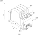
- FIG. 2 illustrates a schematic structural diagram of a surge protector 200 in a locking position of the latching assembly 2 according to an embodiment of the present disclosure.
- the latching assembly 2 includes a sliding blocking component 21.
- the sliding blocking component 21 is movable relative to the base 202 in a predetermined direction Y.
- the sliding blocking component 21 can prevent the functional module 201 from being plugged into and unplugged from the base 202 in the plugging-unplugging direction X.
- FIGS. 3 and 4 show schematic structural diagrams of a sliding blocking component 21 at different viewing angles according to an embodiment of the present disclosure.
- the sliding blocking component 21 includes a sliding main part 210, a first positioning part 211, a buckle part 212, a first driving part 213, and a second operating hole 214.
- the sliding main part 210 is disposed against the installation part 2022.
- the first positioning part 211 and the buckle part 212 are disposed on a side of the sliding main part 210 adjacent to the installation part 2022.
- the first driving part 213 is disposed on a side of the sliding main part 210 away from the installation part 2022.
- the first driving part 213 is capable of driving the sliding main part 210, the first positioning part 211, and the buckle part 212 to move relative to the installation part 2022 in the predetermined direction Y when an external force in the predetermined direction Y is received.
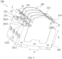
- FIG. 5 illustrates a schematic explosion diagram of a surge protector according to an embodiment of the present disclosure.
- the installation part 2022 is provided with a first operating hole 2023.
- the first operating hole 2023 is provided for an operating component to extend into to fix a circuit inside the base 202.
- a position of the second operating hole 214 on the sliding blocking component 21 corresponds to a position of the first operating hole 2023, and the position of the second operating hole 214 is aligned with the position of the first operating hole 2023 when the latching assembly 2 is in the locking position.
- a fastener such as a bolt may enter interior of the base 202 through the first operating hole 2023, and then use the operating component such as a screwdriver to extend into the first operating hole 2023 to tighten the fastener, so that the circuit in the base 202 is fixed.
- the operating component such as a screwdriver
- the latching assembly 2 includes a sliding installation groove 22.
- the sliding installation groove 22 is provided at a position on the installation part 2022 corresponding to the sliding blocking component 21.
- the sliding installation groove 22 includes a first positioning pin groove 221 provided for insertion of the first positioning part 211 and a buckle sliding groove 222 provided for insertion of the buckle part 212.
- the first positioning pin groove 221 and the buckle sliding groove 222 can guide the sliding blocking component 21 to move relative to the base 202 in the predetermined direction Y when the sliding blocking component 21 is driven by an external force in the predetermined direction Y.
- one end of the first positioning part 211 away from the sliding main part 210 is provided with a first protrusion part 2111.
- the first protrusion part 2111 can abut against the installation part 2022 when the first positioning part 211 is inserted into the first positioning pin groove 221 to prevent the first positioning part 211 from being unplugged from the first positioning pin groove 221.
- One end of the buckle part 212 away from the sliding main part 210 is provided with a second protrusion portion part 2121.
- the second protrusion part 2121 can abut against the installation part 2022 when the buckle part 212 is inserted into the buckle sliding groove 222 to prevent the buckle part 212 from being unplugged from the buckle sliding groove 222.
- the first positioning pin groove 221 is formed with a first positioning hole 2211 and a second positioning hole 2212.
- the first positioning part 211 can be inserted into one of the first positioning hole 2211 and the second positioning hole 2212 and can move to the other of the first positioning hole 2211 and the second positioning hole 2212 when the sliding blocking component 21 moves in the predetermined direction Y.
- the latching assembly 2 is in the unlocking position, and the functional module 201 can be plugged into and unplugged from the recessed part 2021 in the plugging-unplugging direction X.
- the latching assembly 2 When the first positioning part 211 is inserted into the second positioning hole 2212, the latching assembly 2 is in the locking position, and at this time, the main body portion 210 of the sliding blocking component 21 can abut against the guiding component 11 to prevent the functional module 201 from being plugged into and unplugged from the recessed part 2021 in the plugging-unplugging direction X.
- the first positioning part 211 in a process of moving the first positioning part 211 from one of the first positioning hole 2211 and the second positioning hole 2212 to the other, the first positioning part 211 deforms to pass through a gap between the first positioning hole 2211 and the second positioning hole 2212.
- FIG. 6 illustrates a schematic explosion diagram of a surge protector 200 according to another embodiment of the present disclosure.
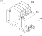
- FIG. 7 illustrates a schematic structural diagram of the surge protector 200 when the latching assembly 2 is in a locking position according to an embodiment of the present disclosure.
- the limiting component 1 includes a first slot 12 provided for the latching assembly 2 to extend into.
- the latching assembly 2 includes a rotating blocking component 23.
- the first slot 12 is disposed on the side wall of the functional module 201 to prevent the functional module 201 from being plugged into and unplugged from the recessed part 2021 in the plugging-unplugging direction X when the rotating blocking component 23 extends into the first slot 12.
- FIG. 8 illustrates a schematic structural diagram of a rotating blocking component 23 according to an embodiment of the present disclosure.
- the rotating blocking component 23 includes a rotating main part 230, a second positioning part 231, a blocking part 232, and a second driving part 233.
- the rotating main part 230 is disposed against the installation part 2022.
- the second positioning part 231 is disposed on a side of the rotating main part 230 adjacent to the installation part 2022.
- the blocking part 232 is disposed on the second positioning part 231 and extends in a direction perpendicular to an axis of the second positioning part 231.
- the second driving part 233 is disposed on the rotating main part 230, and the second driving part 233 extends in a direction perpendicular to the axis of the second positioning part 231 and offset relative to the extending direction of the blocking part 232 by a predetermined angle.
- the latching assembly 2 includes a rotating installation groove 24.
- the rotating installation groove 24 is disposed at a position corresponding to the rotating blocking component 23 on the installation part 2022.
- the rotating installation groove 24 includes a second positioning pin groove 241 provided for inserting of the second positioning part 231 and a second slot 242 provided for the blocking part 232 to pass through.
- the second positioning pin groove 241 is disposed at a position corresponding to the second positioning part 231 on the installation part 2022.
- the second slot 242 is disposed on a side wall of the recessed part 2021, and a position of the second slot 242 coincides with a position of the first slot 12 when the functional module 201 is completely plugged into the recessed part 2021.
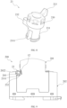
- FIG. 9 illustrates a partial cross-sectional diagram of a surge protector 200 according to another embodiment of the present disclosure.
- the second driving part 233 can drive the rotating main part 230, the second positioning part 231 and the blocking part 232 to rotate relative to the second positioning pin groove 241 in a rotation direction Z when the external force in the rotation direction Z is received, and the blocking part 232 can extend into the second slot 242 under driving of the second driving part 233 when the functional module 201 is completely plugged into the recessed part 2021.
- one end of the second positioning part 231 away from the rotating main part 230 is provided with a third protrusion part 2311.
- the third protrusion part 2311 can abut against the installation part 2022 to prevent the second positioning part 231 from being unplugged from the second positioning pin groove 241.
- the latching assembly 2 when the functional module 201 is completely plugged into the recessed part 2021 and the blocking part 232 extends into the second slot 242, the latching assembly 2 is in the locking position, so that the blocking part 232 can abut against the second slot 242 to prevent the functional module 201 from being unplugged from the recessed part 2021 in the plugging-unplugging direction X.
- the latching assembly 2 is in the unlocking position, so that the functional module 201 can be unplugged from the recessed part 2021 in the plugging-unplugging direction X.
Landscapes
- Casings For Electric Apparatus (AREA)
Abstract
Embodiments of the present disclosure provide a surge protector including a functional module; a base including a recessed part and an installation part, wherein the recessed part is provided for plugging and unplugging of the functional module in a plugging-unplugging direction; a limiting component disposed on a side wall of the functional module; and a latching assembly disposed on the installation part of the base and capable of matching with the limiting component, wherein when the latching assembly is in the unlocking position, the latching assembly allows the functional module to be plugged into and unplugged from the base in the plugging-unplugging direction, and when the latching assembly is in a locking position, the latching assembly can prevent the functional module from being plugged into and unplugged from the base in the plugging-unplugging direction.
Description
- Embodiments of the present disclosure relate to the field of electrical equipment, and more particularly, to a surge protector.
- A surge protector is an electronic apparatus that provides safety protection for various electronic devices, instruments, and communication lines. When a spike current or voltage is suddenly generated in an electrical circuit or a communication line due to external disturbance, the surge protector can shunt in a very short time, thereby avoiding damage to other devices in the circuit by surge.
- The surge protector includes a functional module and a base provided for plugging and unplugging of the functional module. When the functional module has a replacement requirement, the functional module needs to be unplugged from the base, and at this time, the smaller a plugging force between the functional module and the base is set, the convenient it is to unplug the functional module from the base. However, in a normal working process of the surge protector, the functional module may be affected by some shock and vibration in a usage environment, so as to be easily separated from the base, and therefore, an additional locking structure is required between the functional module and the base to prevent the functional module from separating from the base.
- An object of the present disclosure is to provide a surge protector to at least partially solve above problems.
- In a first aspect of the present disclosure, there is provided a surge protector, including: a functional module; a base including a recessed part and an installation part, wherein the recessed part is provided for plugging and unplugging of the functional module in a plugging-unplugging direction; a limiting component disposed on a side wall of the functional module; and a latching assembly disposed on the installation part of the base and capable of matching with the limiting component, wherein when the latching assembly is in the unlocking position, the latching assembly allows the functional module to be plugged into and unplugged from the base in the plugging-unplugging direction, and when the latching assembly is in a locking position, the latching assembly can prevent the functional module from being plugged into and unplugged from the base in the plugging-unplugging direction.
- According to the surge protector provided by the embodiments of the present disclosure, the functional module can be reliably limited to a fixed position by adopting a manner that the limiting component is matched with the latching assembly, so that the functional module is prevented from being separated from the base in a working process.
- In some embodiments, the limiting component includes a guiding component, and the guiding component guides the functional module to move relative to the latching assembly in the plugging-unplugging direction when the functional module is plugged into and unplugged from the recessed part in the plugging-unplugging direction. In such embodiments, the guiding component can be provided to reliably guide the functional module to be plugged into and unplugged from the recessed part in the plugging-unplugging direction.
- In some embodiments, the latching assembly includes a sliding blocking component including a sliding main part, a first positioning part and a buckle part, the sliding main part is disposed against the installation part, and the first positioning part and the buckle part are disposed on a side of the sliding main part adjacent to the installation part; and a sliding installation groove, disposed at a position corresponding to the sliding blocking component on the installation part, wherein the sliding installation groove includes a first positioning pin groove provided for insertion of the first positioning part and a buckle sliding groove provided for insertion of the buckle part, and the first positioning pin groove and the buckle sliding groove can guide the sliding blocking component to move relative to the base in a predetermined direction when the sliding blocking component is driven by an external force in the predetermined direction. In such embodiments, the sliding blocking component can be reliably guided to move relative to the base in the predetermined direction by adopting the first positioning pin groove and the buckle sliding groove.
- In some embodiments, the sliding blocking component further includes a first driving part disposed on a side of the sliding main part away from the installation part, and the first driving part is capable of driving the sliding main part, the first positioning part and the buckle part to move relative to the installation part in the predetermined direction when the external force in a predetermined direction is received. In such embodiments, by providing the first driving part to reliably receive the external force in the predetermined direction and drive the sliding main part, the first positioning part, and the buckle part to smoothly move relative to the installation part in the predetermined direction.
- In some embodiments, the sliding installation groove further includes a guiding groove provided for plugging of the guiding component, and the guiding groove is disposed at a position corresponding to the guiding component on a side wall of the recessed part, so as to guide the guiding component to move in the plugging-unplugging direction when the functional module is plugged into and unplugged from the recessed part in the plugging-unplugging direction. In such embodiments, the guiding groove is capable of sufficiently guiding the guiding component to move in the plugging-unplugging direction when the functional module is plugged into and unplugged from the recessed part in the plugging-unplugging direction.
- In some embodiments, the first positioning pin groove is formed with a first positioning hole and a second positioning hole, the first positioning part can be inserted into one of the first positioning hole and the second positioning hole and can move to the other one of the first positioning hole and the second positioning hole when the sliding blocking component moves in a predetermined direction. In such embodiments, by providing the first positioning hole and the second positioning hole, the first positioning part can be reliably inserted into different positions of the first positioning pin groove relative to the installation part.
- In some embodiments, when the first positioning part is inserted into the first positioning hole, the latching assembly is in the unlocking position, so that the functional module can be plugged into and unplugged from the recessed part in the plugging-unplugging direction, and when the first positioning part is inserted into the second positioning hole, the latching assembly is in the locking position, so that the sliding main part of the sliding blocking component can abut against the guiding component to prevent the functional module from being plugged into and unplugged from the recessed part in the plugging-unplugging direction. In such embodiments, the sliding main part of the sliding blocking component can abut against the guide and reliably prevent the functional module from being plugged into and unplugged from the recessed part in the plugging-unplugging direction.
- In some embodiments, the limiting component includes a first slot provided for the latching assembly to extend into, and the first slot is disposed on the side wall of the functional module to prevent the functional module from being plugged into and unplugged from the recessed part in the plugging-unplugging direction when the latching assembly extends into the first slot. In such embodiments, the functional module can be reliably prevented from being plugged into and unplugged from the recessed part in the plugging-unplugging direction by adopting the latching assembly with the first slot.
- In some embodiments, the lock assembly includes: a rotating blocking component, including a rotating main part, a second positioning part, and a blocking part, the rotating main part being disposed against the installation part, the second positioning part being disposed on a side of the rotating main part adjacent to the installation part, and the blocking part being disposed on the second positioning part and extending in a direction perpendicular to an axis of the second positioning part; and a rotating installation groove including a second positioning pin groove provided for inserting of the second positioning part and a second slot provided for the blocking part to pass through, the second positioning pin groove is disposed at a position corresponding to the rotating blocking component on the installation part, the second slot is disposed on a side wall of the recessed part, and a position of the second slot coincides with a position of the first slot when the functional module is completely plugged into the recessed part. In such embodiments, the blocking part can pass through the second slot and extend into the first slot, so as to reliably prevent the functional module from plugging into and unplugging from the recessed part in the plugging-unplugging direction.
- In some embodiments, the rotating blocking component further includes a second driving part disposed on the rotating main part, the second driving part extends in a direction perpendicular to an axis of the second positioning part and offset relative to an extending direction of the blocking part by a predetermined angle, the second driving part can drive the rotating main part, the second positioning part and the blocking part to rotate relative to the second positioning pin groove in a rotation direction when the external force in the rotation direction is received, and the blocking part can extend into the second slot under driving of the second driving part when the functional module is completely plugged into the recessed part. In such embodiments, the second driving part is provided to reliably receive the external force in the rotation direction and drive the rotating main part, the second positioning part and the blocking part to rotate relative to the second positioning pin groove in the rotation direction.
- In some embodiments, when the functional module is completely plugged into the recessed part and the blocking part extends into the second slot, the latching assembly is in the locking position, so that the blocking part can abut against the second slot to prevent the functional module from being unplugged from the recessed part in the plugging-unplugging direction, and when the functional module is completely plugged into the recessed part and the blocking part does not extend into the second slot, the latching assembly is in the unlocking position, so that the functional module can be unplugged from the recessed part in the plugging-unplugging direction. In such embodiments, the latching assembly can be switched to the locking position and the unlocking position respectively by controlling the blocking part to extend into and out of the second slot.
- It should be understood that the content described in this content section is not intended to limit key features or important features of the embodiments of the present disclosure, nor is it intended to limit a scope of the present disclosure. Other features of the present disclosure will become readily understood from following description.
- The above and other features, advantages, and aspects of various embodiments of the present disclosure will become more apparent from following detailed description taken in conjunction with drawings. In the drawings, the same or similar reference numbers refer to the same or similar elements, wherein:
-
FIG. 1 illustrates a schematic structural diagram of a surge protector when a latching assembly is in an unlocking position according to an embodiment of the present disclosure; -
FIG. 2 illustrates a schematic structural diagram of a surge protector when the latching assembly is in a locking position according to an embodiment of the present disclosure; -
FIGS. 3 and 4 illustrate schematic structural diagrams of a sliding blocking component at different viewing angles according to an embodiment of the present disclosure; -
FIG. 5 illustrates a schematic explosion diagram of a surge protector according to an embodiment of the present disclosure; -
FIG. 6 illustrates a schematic explosion diagram of a surge protector according to another embodiment of the present disclosure; -
FIG. 7 illustrates a schematic structural diagram of a surge protector when the latching assembly is in a locking position according to an embodiment of the present disclosure; -
FIG. 8 illustrates a schematic structural diagram of a rotating blocking component according to an embodiment of the present disclosure; and -
FIG. 9 illustrates a partial cross-sectional diagram of a surge protector according to another embodiment of the present disclosure. -
- 200 surge protector; 201 functional module;
- 202 base; 1 limiting component;
- 2 latching assembly; 11 guiding component;
- 12 first slot; 21 sliding blocking component;
- 22 sliding installation groove; 23 rotating blocking component;
- 24 rotating installation groove; 210 sliding main part;
- 211 first positioning part; 212 buckle part;
- 213 first driving part; 214 second operating hole;
- 221 first positioning pin groove; 222 buckle sliding groove;
- 2021 recessed part; 2022 installation part;
- 2023 first operating hole; 2211 first positioning hole;
- 2212 second positioning hole; 2111 first protrusion part;
- 2121 second protrusion part; 2311 third protrusion part;
- 241 second
positioning pin groove 242 second slot - 231 second positioning part; 230 rotating main part;
- 232 blocking part; 233 second driving part;
- 223 guiding groove; X plugging-unplugging direction;
- Y predetermined direction; Z rotation direction.
- Preferred embodiments of the present disclosure will be described in more detail below with reference to drawings. While the preferred embodiments of the present disclosure are shown in the drawings, it should be understood that the present disclosure may be implemented in various forms and should not be limited by the embodiments set forth herein. Rather, these embodiments are provided to make the present disclosure more thorough and complete, and to completely convey the scope of the present disclosure to those skilled in the art.
- As used herein, the term "include" and variations thereof represent openness, i.e., "include but not limited to". Unless specifically stated, the term "or" means "and/or". The term "based on" means "based at least in part on". The terms "an example embodiment" and "an embodiment" mean "at least one example embodiment". The term "another embodiment" means "at least one further embodiment". The terms "first," "second," and the like may refer to different or identical objects.
- As described above, in a normal working process of a surge protector, a functional module may be affected by some shock and vibration in a usage environment, so as to be easily separated from the base, and therefore an additional locking structure is required between the functional module and the base to prevent the functional module from separating from the base. The embodiments of the present disclosure provide a surge protector, in this scheme, a limiting component is disposed on a function module of the surge protector, a latching assembly is disposed on the base, the functional module can be reliably limited to a fixed position by adopting a manner that the limiting component is matched with the latching assembly, so that the function module is prevented from being separated from the base in a working process. Hereinafter, principles of the present disclosure will be described with reference to
FIGS. 1 to 9 . -
FIG. 1 is a schematic structural diagram of asurge protector 200 when the latchingassembly 2 is in the unlocking position according to an embodiment of the present disclosure. As shown inFIG. 1 , thesurge protector 200 described herein generally includes afunctional module 201, abase 202, a limitingcomponent 1, and a latchingassembly 2. Thebase 202 includes a recessedpart 2021 and aninstallation part 2022. The recessedpart 2021 is provided for plugging and unplugging of thefunctional module 201 in the plugging-unplugging direction X. The limitingcomponent 1 is disposed on a side wall of thefunctional module 201. The latchingassembly 2 is disposed on theinstallation part 2022 of thebase 202 and capable of matching with the limitingcomponent 1. - In an embodiment, as shown in
FIG. 1 , when the latchingassembly 2 is in the unlocking position, the latchingassembly 2 allows thefunctional module 201 to be plugged into and unplugged from the base 202 in the plugging-unplugging direction X. In an embodiment, as shown inFIG. 1 , the limitingcomponent 1 includes a guidingcomponent 11, and the guidingcomponent 11 guides thefunctional module 201 to move relative to the latchingassembly 2 in the plugging-unplugging direction X when thefunctional module 201 is plugged into and unplugged from the recessedpart 2021 in the plugging-unplugging direction X. A guidinggroove 223 is provided at a position corresponding to the guidingcomponent 11 on a side wall of the recessedpart 2021. The guidinggroove 223 can guide the guidingcomponent 11 to move in the plugging-unplugging direction X when thefunctional module 201 is plugged into and unplugged from the recessedpart 2021 in the plugging-unplugging direction X. It should be understood that, based on teaching provided by the present disclosure, those skilled in the art may conceive other types of guiding mechanisms to implement foregoing functions, and these implementations all fall within scope of the present disclosure. -
FIG. 2 illustrates a schematic structural diagram of asurge protector 200 in a locking position of the latchingassembly 2 according to an embodiment of the present disclosure. In an embodiment, as shown inFIGS. 1 and2 , the latchingassembly 2 includes a slidingblocking component 21. The slidingblocking component 21 is movable relative to the base 202 in a predetermined direction Y. When the latchingassembly 2 in the locking position, the slidingblocking component 21 can prevent thefunctional module 201 from being plugged into and unplugged from the base 202 in the plugging-unplugging direction X. -
FIGS. 3 and 4 show schematic structural diagrams of a slidingblocking component 21 at different viewing angles according to an embodiment of the present disclosure. In an embodiment, as shown inFIGS. 3 and 4 , the slidingblocking component 21 includes a slidingmain part 210, afirst positioning part 211, abuckle part 212, afirst driving part 213, and asecond operating hole 214. In an embodiment, as shown inFIGS. 1-4 , the slidingmain part 210 is disposed against theinstallation part 2022. Thefirst positioning part 211 and thebuckle part 212 are disposed on a side of the slidingmain part 210 adjacent to theinstallation part 2022. Thefirst driving part 213 is disposed on a side of the slidingmain part 210 away from theinstallation part 2022. Thefirst driving part 213 is capable of driving the slidingmain part 210, thefirst positioning part 211, and thebuckle part 212 to move relative to theinstallation part 2022 in the predetermined direction Y when an external force in the predetermined direction Y is received. -
FIG. 5 illustrates a schematic explosion diagram of a surge protector according to an embodiment of the present disclosure. In an embodiment, as shown inFIGS. 1 to 5 , theinstallation part 2022 is provided with afirst operating hole 2023. Thefirst operating hole 2023 is provided for an operating component to extend into to fix a circuit inside thebase 202. A position of thesecond operating hole 214 on the slidingblocking component 21 corresponds to a position of thefirst operating hole 2023, and the position of thesecond operating hole 214 is aligned with the position of thefirst operating hole 2023 when the latchingassembly 2 is in the locking position. In an embodiment, when a circuit is installed on thebase 202, a fastener such as a bolt may enter interior of the base 202 through thefirst operating hole 2023, and then use the operating component such as a screwdriver to extend into thefirst operating hole 2023 to tighten the fastener, so that the circuit in thebase 202 is fixed. It should be understood that, based on the teaching provided by the present disclosure, those skilled in the art may conceive that other devices implement the foregoing functions, and these implementations all fall within the scope of the present disclosure. - In an embodiment, as shown in
FIGS. 1 to5 , the latchingassembly 2 includes a slidinginstallation groove 22. The slidinginstallation groove 22 is provided at a position on theinstallation part 2022 corresponding to the slidingblocking component 21. The slidinginstallation groove 22 includes a firstpositioning pin groove 221 provided for insertion of thefirst positioning part 211 and abuckle sliding groove 222 provided for insertion of thebuckle part 212. The firstpositioning pin groove 221 and thebuckle sliding groove 222 can guide the slidingblocking component 21 to move relative to the base 202 in the predetermined direction Y when the slidingblocking component 21 is driven by an external force in the predetermined direction Y. - In an embodiment, as shown in
FIGS. 4 and5 , one end of thefirst positioning part 211 away from the slidingmain part 210 is provided with afirst protrusion part 2111. Thefirst protrusion part 2111 can abut against theinstallation part 2022 when thefirst positioning part 211 is inserted into the firstpositioning pin groove 221 to prevent thefirst positioning part 211 from being unplugged from the firstpositioning pin groove 221. One end of thebuckle part 212 away from the slidingmain part 210 is provided with a secondprotrusion portion part 2121. Thesecond protrusion part 2121 can abut against theinstallation part 2022 when thebuckle part 212 is inserted into thebuckle sliding groove 222 to prevent thebuckle part 212 from being unplugged from thebuckle sliding groove 222. - In an embodiment, as shown in
FIGS. 1 to 5 , the firstpositioning pin groove 221 is formed with afirst positioning hole 2211 and asecond positioning hole 2212. When the slidingblocking component 21 is inserted into the slidinginstallation groove 22, thefirst positioning part 211 can be inserted into one of thefirst positioning hole 2211 and thesecond positioning hole 2212 and can move to the other of thefirst positioning hole 2211 and thesecond positioning hole 2212 when the slidingblocking component 21 moves in the predetermined direction Y. When thefirst positioning part 211 is inserted into thefirst positioning hole 2211, the latchingassembly 2 is in the unlocking position, and thefunctional module 201 can be plugged into and unplugged from the recessedpart 2021 in the plugging-unplugging direction X. When thefirst positioning part 211 is inserted into thesecond positioning hole 2212, the latchingassembly 2 is in the locking position, and at this time, themain body portion 210 of the slidingblocking component 21 can abut against the guidingcomponent 11 to prevent thefunctional module 201 from being plugged into and unplugged from the recessedpart 2021 in the plugging-unplugging direction X. In an embodiment, in a process of moving thefirst positioning part 211 from one of thefirst positioning hole 2211 and thesecond positioning hole 2212 to the other, thefirst positioning part 211 deforms to pass through a gap between thefirst positioning hole 2211 and thesecond positioning hole 2212. It should be understood that, based on the teaching provided by the present disclosure, those skilled in the art may conceive other types of structures to implement the foregoing functions, and these implementations all fall within the scope of the present disclosure. -
FIG. 6 illustrates a schematic explosion diagram of asurge protector 200 according to another embodiment of the present disclosure.FIG. 7 illustrates a schematic structural diagram of thesurge protector 200 when the latchingassembly 2 is in a locking position according to an embodiment of the present disclosure. In an embodiment, as shown inFIGS. 6 and7 , the limitingcomponent 1 includes afirst slot 12 provided for the latchingassembly 2 to extend into. The latchingassembly 2 includes arotating blocking component 23. Thefirst slot 12 is disposed on the side wall of thefunctional module 201 to prevent thefunctional module 201 from being plugged into and unplugged from the recessedpart 2021 in the plugging-unplugging direction X when therotating blocking component 23 extends into thefirst slot 12. -
FIG. 8 illustrates a schematic structural diagram of arotating blocking component 23 according to an embodiment of the present disclosure. In an embodiment, as shown inFIG. 8 , therotating blocking component 23 includes a rotatingmain part 230, asecond positioning part 231, a blockingpart 232, and asecond driving part 233. The rotatingmain part 230 is disposed against theinstallation part 2022. Thesecond positioning part 231 is disposed on a side of the rotatingmain part 230 adjacent to theinstallation part 2022. The blockingpart 232 is disposed on thesecond positioning part 231 and extends in a direction perpendicular to an axis of thesecond positioning part 231. Thesecond driving part 233 is disposed on the rotatingmain part 230, and thesecond driving part 233 extends in a direction perpendicular to the axis of thesecond positioning part 231 and offset relative to the extending direction of the blockingpart 232 by a predetermined angle. - In an embodiment, as shown in
FIGS. 6 to 8 , the latchingassembly 2 includes arotating installation groove 24. Therotating installation groove 24 is disposed at a position corresponding to therotating blocking component 23 on theinstallation part 2022. Therotating installation groove 24 includes a secondpositioning pin groove 241 provided for inserting of thesecond positioning part 231 and asecond slot 242 provided for the blockingpart 232 to pass through. The secondpositioning pin groove 241 is disposed at a position corresponding to thesecond positioning part 231 on theinstallation part 2022. Thesecond slot 242 is disposed on a side wall of the recessedpart 2021, and a position of thesecond slot 242 coincides with a position of thefirst slot 12 when thefunctional module 201 is completely plugged into the recessedpart 2021. It should be understood that, based on the teaching provided by the present disclosure, those skilled in the art may conceive other types of structures to implement the foregoing functions, and these implementations all fall within the scope of the present disclosure. -
FIG. 9 illustrates a partial cross-sectional diagram of asurge protector 200 according to another embodiment of the present disclosure. In an embodiment, as shown inFIG. 6 to 9 , thesecond driving part 233 can drive the rotatingmain part 230, thesecond positioning part 231 and the blockingpart 232 to rotate relative to the secondpositioning pin groove 241 in a rotation direction Z when the external force in the rotation direction Z is received, and the blockingpart 232 can extend into thesecond slot 242 under driving of thesecond driving part 233 when thefunctional module 201 is completely plugged into the recessedpart 2021. - In an embodiment, as shown in
FIGS. 8 and 9 , one end of thesecond positioning part 231 away from the rotatingmain part 230 is provided with athird protrusion part 2311. Thethird protrusion part 2311 can abut against theinstallation part 2022 to prevent thesecond positioning part 231 from being unplugged from the secondpositioning pin groove 241. - In an embodiment, as shown in
FIGS. 6 to 9 , when thefunctional module 201 is completely plugged into the recessedpart 2021 and the blockingpart 232 extends into thesecond slot 242, the latchingassembly 2 is in the locking position, so that the blockingpart 232 can abut against thesecond slot 242 to prevent thefunctional module 201 from being unplugged from the recessedpart 2021 in the plugging-unplugging direction X. When thefunctional module 201 is completely plugged into the recessedpart 2021 and the blockingpart 232 does not extend into thesecond slot 242, the latchingassembly 2 is in the unlocking position, so that thefunctional module 201 can be unplugged from the recessedpart 2021 in the plugging-unplugging direction X. - Various embodiments of the present disclosure have been described above, which are exemplary, not exhaustive, and are not limited to disclosed embodiments. Many modifications and variations will be apparent to those of ordinary skill in the art without departing from the scope and spirit of illustrated embodiments. Selection of the terms used herein is intended to best explain the principles of the embodiments, practical applications, or technical improvements in the marketplace, or to enable others of ordinary skill in the art to understand the embodiments disclosed herein.
Claims (11)
- A surge protector (200), characterized by comprising:a functional module (201);a base (202) comprising a recessed part (2021) and an installation part (2022), wherein the recessed part (2021) is provided for plugging and unplugging of the functional module (201) in a plugging-unplugging direction (X);a limiting component (1) disposed on a side wall of the functional module (201); anda latching assembly (2) disposed on the installation part (2022) of the base (202) and capable of matching with the limiting component (1), wherein when the latching assembly (2) is in an unlocking position, the latching assembly (2) allows the functional module (201) to be plugged into and unplugged from the base (202) in the plugging-unplugging direction (X), and when the latching assembly (2) is in a locking position, the latching assembly (2) can prevent the functional module (201) from being plugged into and unplugged from the base (202) in the plugging-unplugging direction (X).
- The surge protector (200) of claim 1, characterized in that the limiting component (1) comprises a guiding component (11), and the guiding component (11) guides the functional module (201) to move relative to the latching assembly (2) in the plugging-unplugging direction (X) when the functional module (201) is plugged into and unplugged from the recessed part (2021) in the plugging-unplugging direction (X).
- The surge protector (200) of claim 2, characterized in that the latching assembly (2) comprises:a sliding blocking component (21) comprising a sliding main part (210), a first positioning part (211) and a buckle part (212), wherein the sliding main part (210) is disposed against the installation part (2022), and the first positioning part (211) and the buckle part (212) are disposed on a side of the sliding main part (210) adjacent to the installation part (2022); anda sliding installation groove (22) disposed at a position corresponding to the sliding blocking component (21) on the installation part (2022), wherein the sliding installation groove (22) comprises a first positioning pin groove (221) provided for insertion of the first positioning part (211) and a buckle sliding groove (222) provided for insertion of the buckle part (212), and the first positioning pin groove (221) and the buckle sliding groove (222) can guide the sliding blocking component (21) to move relative to the base (202) in a predetermined direction (Y) when the sliding blocking component (21) is driven by an external force in the predetermined direction (Y).
- The surge protector (200) of claim 3, characterized in that the sliding blocking component (21) further comprises a first driving part (213) disposed on a side of the sliding main part (210) away from the installation part (2022), and the first driving part (213) is capable of driving the sliding main part (210), the first positioning part (211) and the buckle part (212) to move relative to the installation part (2022) in the predetermined direction (Y) when the external force in the predetermined direction (Y) is received.
- The surge protector (200) of claim 3, characterized in that the sliding installation groove (22) further comprises a guiding groove (223) provided for plugging of the guiding component (11), and the guiding groove (223) is disposed at a position corresponding to the guiding component (11) on a side wall of the recessed part (2021), so as to guide the guiding component (11) to move in the plugging-unplugging direction (X) when the functional module (201) is plugged into and unplugged from the recessed part (2021) in the plugging-unplugging direction (X).
- The surge protector (200) of claim 3, characterized in that the first positioning pin groove (221) is formed with a first positioning hole (2211) and a second positioning hole (2212), the first positioning part (211) can be inserted into one of the first positioning hole (2211) and the second positioning hole (2212) and can move to the other one of the first positioning hole (2211) and the second positioning hole (2212) when the sliding blocking component (21) moves in the predetermined direction (Y).
- The surge protector (200) of claim 6, characterized in that when the first positioning part (211) is inserted into the first positioning hole (2211), the latching assembly (2) is in the unlocking position, so that the functional module (201) can be plugged into and unplugged from the recessed part (2021) in the plugging-unplugging direction (X), and when the first positioning part (211) is inserted into the second positioning hole (2212), the latching assembly (2) is in the locking position, so that the sliding main part (210) of the sliding blocking component (21) can abut against the guiding component (11) to prevent the functional module (201) from being plugged into and unplugged from the recessed part (2021) in the plugging-unplugging direction (X).
- The surge protector (200) of claim 1, characterized in that the limiting component (1) comprises a first slot (12) provided for the latching assembly (2) to extend into, and the first slot (12) is disposed on the side wall of the functional module (201) to prevent the functional module (201) from being plugged into and unplugged from the recessed part (2021) in the plugging-unplugging direction (X) when the latching assembly (2) extends into the first slot (12).
- The surge protector (200) of claim 8, characterized in that the latching assembly (2) comprises:a rotating blocking component (23) comprising a rotating main part (230), a second positioning part (231) and a blocking part (232), the rotating main part (230) being disposed against the installation part (2022), the second positioning part (231) being disposed on a side of the rotating main part (230) adjacent to the installation part (2022), and the blocking part (232) being disposed on the second positioning part (231) and extending in a direction perpendicular to an axis of the second positioning part (231); anda rotating installation groove (24) comprising a second positioning pin groove (241) provided for inserting of the second positioning part (231) and a second slot (242) provided for the blocking part (232) to pass through, the second positioning pin groove (241) is disposed at a position corresponding to the rotating blocking component (23) on the installation part (2022), the second slot (242) is disposed on a side wall of the recessed part (2021), and a position of the second slot (242) coincides with a position of the first slot (12) when the functional module (201) is completely plugged into the recessed part (2021).
- The surge protector (200) of claim 9, characterized in that the rotating blocking component (23) further comprises a second driving part (233) disposed on the rotating main part (230), the second driving part (233) extends in a direction perpendicular to the axis of the second positioning part (231) and offset relative to an extending direction of the blocking part (232) by a predetermined angle, the second driving part (233) can drive the rotating main part (230), the second positioning part (231) and the blocking part (232) to rotate relative to the second positioning pin groove (241) in a rotation direction (Z) when the external force in the rotation direction (Z) is received, and the blocking part (232) can extend into the second slot (242) under driving of the second driving part (233) when the functional module (201) is completely plugged into the recessed part (2021).
- The surge protector (200) of claim 9, characterized in that when the functional module (201) is completely plugged into the recessed part (2021) and the blocking part (232) extends into the second slot (242), the latching assembly (2) is in the locking position, so that the blocking part (232) can abut against the second slot (242) to prevent the functional module (201) from being unplugged from the recessed part (2021) in the plugging-unplugging direction (X), and when the functional module (201) is completely plugged into the recessed part (2021) and the blocking part (232) does not extend into the second slot (242), the latching assembly (2) is in the unlocking position, so that the functional module (201) can be unplugged from the recessed part (2021) in the plugging-unplugging direction (X).
Applications Claiming Priority (1)
| Application Number | Priority Date | Filing Date | Title |
|---|---|---|---|
| CN202322424120.1U CN220797802U (en) | 2023-09-06 | 2023-09-06 | Surge protector |
Publications (1)
| Publication Number | Publication Date |
|---|---|
| EP4521437A1 true EP4521437A1 (en) | 2025-03-12 |
Family
ID=90661824
Family Applications (1)
| Application Number | Title | Priority Date | Filing Date |
|---|---|---|---|
| EP24306352.6A Pending EP4521437A1 (en) | 2023-09-06 | 2024-08-12 | Surge protector |
Country Status (2)
| Country | Link |
|---|---|
| EP (1) | EP4521437A1 (en) |
| CN (1) | CN220797802U (en) |
Citations (5)
| Publication number | Priority date | Publication date | Assignee | Title |
|---|---|---|---|---|
| DE102008017423A1 (en) * | 2008-04-03 | 2009-10-15 | Phoenix Contact Gmbh & Co. Kg | Fixing device for fixing housing of surge protective device at device base in e.g. industrial installation, has detachable turning lock arranged in base part to produce form-fit locking between base part and plug part |
| CN102340136A (en) * | 2010-07-28 | 2012-02-01 | 上海电科电器科技有限公司 | Pluggable surge protector |
| EP3236548B1 (en) * | 2016-04-21 | 2021-07-07 | Raycap, Surge Protective Devices, Ltd. | Din rail device mount assemblies, systems and methods including locking mechanisms |
| US20220278487A1 (en) * | 2019-07-19 | 2022-09-01 | Dehn Se + Co Kg | Plug-in module for a rail-mounted device, and rail-mounted device |
| US20220346255A1 (en) * | 2019-10-02 | 2022-10-27 | Phoenix Contact Gmbh & Co. Kg | Electrical device having a locking device |
-
2023
- 2023-09-06 CN CN202322424120.1U patent/CN220797802U/en active Active
-
2024
- 2024-08-12 EP EP24306352.6A patent/EP4521437A1/en active Pending
Patent Citations (5)
| Publication number | Priority date | Publication date | Assignee | Title |
|---|---|---|---|---|
| DE102008017423A1 (en) * | 2008-04-03 | 2009-10-15 | Phoenix Contact Gmbh & Co. Kg | Fixing device for fixing housing of surge protective device at device base in e.g. industrial installation, has detachable turning lock arranged in base part to produce form-fit locking between base part and plug part |
| CN102340136A (en) * | 2010-07-28 | 2012-02-01 | 上海电科电器科技有限公司 | Pluggable surge protector |
| EP3236548B1 (en) * | 2016-04-21 | 2021-07-07 | Raycap, Surge Protective Devices, Ltd. | Din rail device mount assemblies, systems and methods including locking mechanisms |
| US20220278487A1 (en) * | 2019-07-19 | 2022-09-01 | Dehn Se + Co Kg | Plug-in module for a rail-mounted device, and rail-mounted device |
| US20220346255A1 (en) * | 2019-10-02 | 2022-10-27 | Phoenix Contact Gmbh & Co. Kg | Electrical device having a locking device |
Also Published As
| Publication number | Publication date |
|---|---|
| CN220797802U (en) | 2024-04-16 |
Similar Documents
| Publication | Publication Date | Title |
|---|---|---|
| US6146210A (en) | Connector assembly that prevents polarization problems and uses a single aperture to perform both latching functions and guide functions | |
| US6383036B1 (en) | Electrical plug-and-socket device comprising a fixing unit | |
| US6116941A (en) | Device for locking two mating connectors | |
| US11482810B2 (en) | Secondary securing means, electrical plug connector and electrical plug connection | |
| US20050176274A1 (en) | Modular signal and power connection device | |
| US6273735B1 (en) | Rotating turret side-entry retractable jack | |
| US10312626B2 (en) | Electrical connector with terminal alignment plate and secondary lock detection | |
| US7621680B2 (en) | In-ceiling surveillance housing | |
| US10305223B2 (en) | Connector with projecting sub-connector lance | |
| US20240026902A1 (en) | Attachment structure for attaching fan unit to main body of electrical equipment, connector connecting main body of electrical equipment and fan unit, and electrical equipment | |
| EP4300714A1 (en) | Connector assembly | |
| US7192307B1 (en) | Quick release locking latch for a panel mount connector | |
| US5026297A (en) | Electrical socket assembly for single in-line circuit package | |
| US6081419A (en) | Protection device for an electronic instrument and method | |
| CN220797802U (en) | Surge protector | |
| EP1006380A1 (en) | Electrical and/or optical connector | |
| US5251104A (en) | Enclosure latch system including a bearing surface tapering from flat to cylindrical | |
| US10631419B1 (en) | Mounting bracket for encrypted touch module | |
| US11805614B2 (en) | Contact protection cover held in a locked position by a circuit breaker | |
| US11264759B1 (en) | Connector with integrated primary lock reinforcement and terminal position assurance | |
| US20090017690A1 (en) | Electrical connector assembly and male type connector | |
| WO2023163093A1 (en) | Terminal block | |
| US20250343381A1 (en) | Attachable housing for mounting on a wall having an opening | |
| US7393212B2 (en) | Rotating power receptacle | |
| US12317433B2 (en) | Case of electronic device and unlocking method thereof |
Legal Events
| Date | Code | Title | Description |
|---|---|---|---|
| PUAI | Public reference made under article 153(3) epc to a published international application that has entered the european phase |
Free format text: ORIGINAL CODE: 0009012 |
|
| STAA | Information on the status of an ep patent application or granted ep patent |
Free format text: STATUS: THE APPLICATION HAS BEEN PUBLISHED |
|
| AK | Designated contracting states |
Kind code of ref document: A1 Designated state(s): AL AT BE BG CH CY CZ DE DK EE ES FI FR GB GR HR HU IE IS IT LI LT LU LV MC ME MK MT NL NO PL PT RO RS SE SI SK SM TR |
|
| STAA | Information on the status of an ep patent application or granted ep patent |
Free format text: STATUS: REQUEST FOR EXAMINATION WAS MADE |
|
| 17P | Request for examination filed |
Effective date: 20250910 |
|
| STAA | Information on the status of an ep patent application or granted ep patent |
Free format text: STATUS: EXAMINATION IS IN PROGRESS |