EP4521388A1 - Pixel circuit and display apparatus including the same - Google Patents
Pixel circuit and display apparatus including the same Download PDFInfo
- Publication number
- EP4521388A1 EP4521388A1 EP24198914.4A EP24198914A EP4521388A1 EP 4521388 A1 EP4521388 A1 EP 4521388A1 EP 24198914 A EP24198914 A EP 24198914A EP 4521388 A1 EP4521388 A1 EP 4521388A1
- Authority
- EP
- European Patent Office
- Prior art keywords
- transistor
- node
- electrically connected
- electrode
- voltage
- Prior art date
- Legal status (The legal status is an assumption and is not a legal conclusion. Google has not performed a legal analysis and makes no representation as to the accuracy of the status listed.)
- Pending
Links
Images









Classifications
-
- G—PHYSICS
- G09—EDUCATION; CRYPTOGRAPHY; DISPLAY; ADVERTISING; SEALS
- G09G—ARRANGEMENTS OR CIRCUITS FOR CONTROL OF INDICATING DEVICES USING STATIC MEANS TO PRESENT VARIABLE INFORMATION
- G09G3/00—Control arrangements or circuits, of interest only in connection with visual indicators other than cathode-ray tubes
- G09G3/20—Control arrangements or circuits, of interest only in connection with visual indicators other than cathode-ray tubes for presentation of an assembly of a number of characters, e.g. a page, by composing the assembly by combination of individual elements arranged in a matrix no fixed position being assigned to or needed to be assigned to the individual characters or partial characters
- G09G3/22—Control arrangements or circuits, of interest only in connection with visual indicators other than cathode-ray tubes for presentation of an assembly of a number of characters, e.g. a page, by composing the assembly by combination of individual elements arranged in a matrix no fixed position being assigned to or needed to be assigned to the individual characters or partial characters using controlled light sources
- G09G3/30—Control arrangements or circuits, of interest only in connection with visual indicators other than cathode-ray tubes for presentation of an assembly of a number of characters, e.g. a page, by composing the assembly by combination of individual elements arranged in a matrix no fixed position being assigned to or needed to be assigned to the individual characters or partial characters using controlled light sources using electroluminescent panels
- G09G3/32—Control arrangements or circuits, of interest only in connection with visual indicators other than cathode-ray tubes for presentation of an assembly of a number of characters, e.g. a page, by composing the assembly by combination of individual elements arranged in a matrix no fixed position being assigned to or needed to be assigned to the individual characters or partial characters using controlled light sources using electroluminescent panels semiconductive, e.g. using light-emitting diodes [LED]
- G09G3/3208—Control arrangements or circuits, of interest only in connection with visual indicators other than cathode-ray tubes for presentation of an assembly of a number of characters, e.g. a page, by composing the assembly by combination of individual elements arranged in a matrix no fixed position being assigned to or needed to be assigned to the individual characters or partial characters using controlled light sources using electroluminescent panels semiconductive, e.g. using light-emitting diodes [LED] organic, e.g. using organic light-emitting diodes [OLED]
- G09G3/3225—Control arrangements or circuits, of interest only in connection with visual indicators other than cathode-ray tubes for presentation of an assembly of a number of characters, e.g. a page, by composing the assembly by combination of individual elements arranged in a matrix no fixed position being assigned to or needed to be assigned to the individual characters or partial characters using controlled light sources using electroluminescent panels semiconductive, e.g. using light-emitting diodes [LED] organic, e.g. using organic light-emitting diodes [OLED] using an active matrix
- G09G3/3233—Control arrangements or circuits, of interest only in connection with visual indicators other than cathode-ray tubes for presentation of an assembly of a number of characters, e.g. a page, by composing the assembly by combination of individual elements arranged in a matrix no fixed position being assigned to or needed to be assigned to the individual characters or partial characters using controlled light sources using electroluminescent panels semiconductive, e.g. using light-emitting diodes [LED] organic, e.g. using organic light-emitting diodes [OLED] using an active matrix with pixel circuitry controlling the current through the light-emitting element
-
- G—PHYSICS
- G09—EDUCATION; CRYPTOGRAPHY; DISPLAY; ADVERTISING; SEALS
- G09G—ARRANGEMENTS OR CIRCUITS FOR CONTROL OF INDICATING DEVICES USING STATIC MEANS TO PRESENT VARIABLE INFORMATION
- G09G3/00—Control arrangements or circuits, of interest only in connection with visual indicators other than cathode-ray tubes
- G09G3/20—Control arrangements or circuits, of interest only in connection with visual indicators other than cathode-ray tubes for presentation of an assembly of a number of characters, e.g. a page, by composing the assembly by combination of individual elements arranged in a matrix no fixed position being assigned to or needed to be assigned to the individual characters or partial characters
- G09G3/22—Control arrangements or circuits, of interest only in connection with visual indicators other than cathode-ray tubes for presentation of an assembly of a number of characters, e.g. a page, by composing the assembly by combination of individual elements arranged in a matrix no fixed position being assigned to or needed to be assigned to the individual characters or partial characters using controlled light sources
- G09G3/30—Control arrangements or circuits, of interest only in connection with visual indicators other than cathode-ray tubes for presentation of an assembly of a number of characters, e.g. a page, by composing the assembly by combination of individual elements arranged in a matrix no fixed position being assigned to or needed to be assigned to the individual characters or partial characters using controlled light sources using electroluminescent panels
- G09G3/32—Control arrangements or circuits, of interest only in connection with visual indicators other than cathode-ray tubes for presentation of an assembly of a number of characters, e.g. a page, by composing the assembly by combination of individual elements arranged in a matrix no fixed position being assigned to or needed to be assigned to the individual characters or partial characters using controlled light sources using electroluminescent panels semiconductive, e.g. using light-emitting diodes [LED]
-
- G—PHYSICS
- G09—EDUCATION; CRYPTOGRAPHY; DISPLAY; ADVERTISING; SEALS
- G09G—ARRANGEMENTS OR CIRCUITS FOR CONTROL OF INDICATING DEVICES USING STATIC MEANS TO PRESENT VARIABLE INFORMATION
- G09G2300/00—Aspects of the constitution of display devices
- G09G2300/04—Structural and physical details of display devices
- G09G2300/0421—Structural details of the set of electrodes
- G09G2300/0426—Layout of electrodes and connections
-
- G—PHYSICS
- G09—EDUCATION; CRYPTOGRAPHY; DISPLAY; ADVERTISING; SEALS
- G09G—ARRANGEMENTS OR CIRCUITS FOR CONTROL OF INDICATING DEVICES USING STATIC MEANS TO PRESENT VARIABLE INFORMATION
- G09G2300/00—Aspects of the constitution of display devices
- G09G2300/08—Active matrix structure, i.e. with use of active elements, inclusive of non-linear two terminal elements, in the pixels together with light emitting or modulating elements
- G09G2300/0809—Several active elements per pixel in active matrix panels
- G09G2300/0819—Several active elements per pixel in active matrix panels used for counteracting undesired variations, e.g. feedback or autozeroing
-
- G—PHYSICS
- G09—EDUCATION; CRYPTOGRAPHY; DISPLAY; ADVERTISING; SEALS
- G09G—ARRANGEMENTS OR CIRCUITS FOR CONTROL OF INDICATING DEVICES USING STATIC MEANS TO PRESENT VARIABLE INFORMATION
- G09G2300/00—Aspects of the constitution of display devices
- G09G2300/08—Active matrix structure, i.e. with use of active elements, inclusive of non-linear two terminal elements, in the pixels together with light emitting or modulating elements
- G09G2300/0809—Several active elements per pixel in active matrix panels
- G09G2300/0842—Several active elements per pixel in active matrix panels forming a memory circuit, e.g. a dynamic memory with one capacitor
- G09G2300/0852—Several active elements per pixel in active matrix panels forming a memory circuit, e.g. a dynamic memory with one capacitor being a dynamic memory with more than one capacitor
-
- G—PHYSICS
- G09—EDUCATION; CRYPTOGRAPHY; DISPLAY; ADVERTISING; SEALS
- G09G—ARRANGEMENTS OR CIRCUITS FOR CONTROL OF INDICATING DEVICES USING STATIC MEANS TO PRESENT VARIABLE INFORMATION
- G09G2300/00—Aspects of the constitution of display devices
- G09G2300/08—Active matrix structure, i.e. with use of active elements, inclusive of non-linear two terminal elements, in the pixels together with light emitting or modulating elements
- G09G2300/0809—Several active elements per pixel in active matrix panels
- G09G2300/0842—Several active elements per pixel in active matrix panels forming a memory circuit, e.g. a dynamic memory with one capacitor
- G09G2300/0861—Several active elements per pixel in active matrix panels forming a memory circuit, e.g. a dynamic memory with one capacitor with additional control of the display period without amending the charge stored in a pixel memory, e.g. by means of additional select electrodes
-
- G—PHYSICS
- G09—EDUCATION; CRYPTOGRAPHY; DISPLAY; ADVERTISING; SEALS
- G09G—ARRANGEMENTS OR CIRCUITS FOR CONTROL OF INDICATING DEVICES USING STATIC MEANS TO PRESENT VARIABLE INFORMATION
- G09G2310/00—Command of the display device
- G09G2310/02—Addressing, scanning or driving the display screen or processing steps related thereto
- G09G2310/0243—Details of the generation of driving signals
- G09G2310/0251—Precharge or discharge of pixel before applying new pixel voltage
-
- G—PHYSICS
- G09—EDUCATION; CRYPTOGRAPHY; DISPLAY; ADVERTISING; SEALS
- G09G—ARRANGEMENTS OR CIRCUITS FOR CONTROL OF INDICATING DEVICES USING STATIC MEANS TO PRESENT VARIABLE INFORMATION
- G09G2310/00—Command of the display device
- G09G2310/02—Addressing, scanning or driving the display screen or processing steps related thereto
- G09G2310/0262—The addressing of the pixel, in a display other than an active matrix LCD, involving the control of two or more scan electrodes or two or more data electrodes, e.g. pixel voltage dependent on signals of two data electrodes
-
- G—PHYSICS
- G09—EDUCATION; CRYPTOGRAPHY; DISPLAY; ADVERTISING; SEALS
- G09G—ARRANGEMENTS OR CIRCUITS FOR CONTROL OF INDICATING DEVICES USING STATIC MEANS TO PRESENT VARIABLE INFORMATION
- G09G2310/00—Command of the display device
- G09G2310/02—Addressing, scanning or driving the display screen or processing steps related thereto
- G09G2310/0264—Details of driving circuits
- G09G2310/0267—Details of drivers for scan electrodes, other than drivers for liquid crystal, plasma or OLED displays
-
- G—PHYSICS
- G09—EDUCATION; CRYPTOGRAPHY; DISPLAY; ADVERTISING; SEALS
- G09G—ARRANGEMENTS OR CIRCUITS FOR CONTROL OF INDICATING DEVICES USING STATIC MEANS TO PRESENT VARIABLE INFORMATION
- G09G2310/00—Command of the display device
- G09G2310/02—Addressing, scanning or driving the display screen or processing steps related thereto
- G09G2310/0264—Details of driving circuits
- G09G2310/0275—Details of drivers for data electrodes, other than drivers for liquid crystal, plasma or OLED displays, not related to handling digital grey scale data or to communication of data to the pixels by means of a current
-
- G—PHYSICS
- G09—EDUCATION; CRYPTOGRAPHY; DISPLAY; ADVERTISING; SEALS
- G09G—ARRANGEMENTS OR CIRCUITS FOR CONTROL OF INDICATING DEVICES USING STATIC MEANS TO PRESENT VARIABLE INFORMATION
- G09G2310/00—Command of the display device
- G09G2310/06—Details of flat display driving waveforms
- G09G2310/061—Details of flat display driving waveforms for resetting or blanking
-
- G—PHYSICS
- G09—EDUCATION; CRYPTOGRAPHY; DISPLAY; ADVERTISING; SEALS
- G09G—ARRANGEMENTS OR CIRCUITS FOR CONTROL OF INDICATING DEVICES USING STATIC MEANS TO PRESENT VARIABLE INFORMATION
- G09G2310/00—Command of the display device
- G09G2310/08—Details of timing specific for flat panels, other than clock recovery
-
- G—PHYSICS
- G09—EDUCATION; CRYPTOGRAPHY; DISPLAY; ADVERTISING; SEALS
- G09G—ARRANGEMENTS OR CIRCUITS FOR CONTROL OF INDICATING DEVICES USING STATIC MEANS TO PRESENT VARIABLE INFORMATION
- G09G2330/00—Aspects of power supply; Aspects of display protection and defect management
- G09G2330/02—Details of power systems and of start or stop of display operation
- G09G2330/021—Power management, e.g. power saving
Definitions
- Embodiments of the disclosure relate to a pixel circuit driven according to a pulse width modulation technique, operating an internal compensation of a threshold voltage, including fewer transistors, and thus, applicable to a ultra-high resolution display apparatus and a display apparatus including the pixel circuit.
- a display apparatus includes a display panel and a display panel driver.
- the display panel includes multiple gate lines, multiple data lines, multiple emission lines and multiple pixels.
- the display panel driver includes a gate driver, a data driver, an emission driver and a driving controller.
- the gate driver outputs gate signals to the gate lines.
- the data driver outputs data voltages to the data lines.
- the emission driver outputs emission signals to the emission lines.
- the driving controller controls the gate driver, the data driver and the emission driver.
- An earlier pixel circuit driven according to a pulse width modulation technique and operating internal compensation of the threshold voltage may include nineteen or more transistors and three or more capacitors. In case that the pixel circuit includes nineteen or more transistors and three or more capacitors, the pixel circuit may not be applied to an ultra-high resolution display apparatus due to a limitation in integration.
- Embodiments of the inventive concept provide a pixel circuit driven according to a pulse width modulation technique, operating an internal compensation of a threshold voltage, including fewer transistors, and thus, applicable to a ultra-high resolution display apparatus.
- Embodiments of the inventive concept also provide a display apparatus including the pixel circuit.
- the pixel circuit may include a first transistor including a control electrode electrically connected to a first node, a first electrode electrically connected to a second node and a second electrode electrically connected to a third node, a second transistor configured to apply a first data voltage to the first transistor, a third transistor electrically connected to the first node and the third node, a fourth transistor including a control electrode electrically connected to a fourth node, a first electrode electrically connected to a fifth node and a second electrode electrically connected to a sixth node, a fifth transistor configured to apply a second data voltage to the fourth transistor, an sixth transistor electrically connected to the fourth node and the sixth node and a light emitting element that emits light based on the first data voltage and the second data voltage.
- the pixel circuit may include a first circuit, a second circuit and the light emitting element.
- the first circuit may include the first to third transistors.
- the second circuit may include the sixth to eighth transistors.
- the first circuit may be a pulse width modulation circuit for a pulse width modulation.
- the second circuit may be a constant current generation circuit for a constant current generation.
- the pixel circuit may further include a first capacitor including a first electrode that receives a sweep signal and a second electrode electrically connected to the first node.
- the pixel circuit may further include a second capacitor including a first electrode that receives a second power voltage and a second electrode electrically connected to the fourth node.
- the pixel circuit may further include a seventh transistor electrically connected to the third node and the fourth node, an eighth transistor electrically connected to the sixth node and an anode electrode of the light emitting element and a ninth transistor configured to apply an initialization voltage to the anode electrode.
- the third transistor, the seventh transistor, the sixth transistor, the eighth transistor and the ninth transistor may be turned on in an initialization period.
- the first circuit may include the first to fifth transistors and the first capacitor.
- the second circuit may include sixth to eleventh and the second capacitor.
- the third transistor, the seventh transistor, the sixth transistor, the eighth transistor and the ninth transistor may be turned on and the initialization voltage may have a first voltage in a first initialization period.
- the third transistor may be turned off, the sixth transistor, the eighth transistor and the ninth transistor may be turned on and the initialization voltage may have the first voltage in a second initialization period subsequent to the first initialization period.
- the third transistor, the sixth transistor and the eighth transistor may be turned off, the ninth transistor may be turned on and the initialization voltage may have a second voltage different from the first voltage in the third initialization period subsequent to the second initialization period.
- the third transistor, the seventh transistor, the sixth transistor, the eighth transistor and the ninth transistor may be turned on and the initialization voltage may have a first voltage in a first initialization period.
- the third transistor may be turned off, the sixth transistor, the eighth transistor and the ninth transistor may be turned on and the initialization voltage may have a second voltage different from the first voltage in a second initialization period subsequent to the first initialization period.
- the third transistor, the sixth transistor and the eighth transistor may be turned off, the ninth transistor may be turned on and the initialization voltage may have a third voltage different from the first voltage and the second voltage in a third initialization period subsequent to the second initialization period.
- the first transistor, the second transistor, the fourth transistor and the fifth transistor may be P-type transistors.
- the third transistor and the sixth transistor may be N-type transistors.
- the pixel circuit may further include a ninth transistor configured to apply an initialization voltage to an anode electrode of the light emitting element.
- the ninth transistor may be an N-type transistor.
- the pixel circuit may further include a ninth transistor configured to apply an initialization voltage to an anode electrode of the light emitting element.
- the ninth transistor may be an N-type transistor.
- the first transistor, the second transistor, the third transistor, the fourth transistor, the fifth transistor and the sixth transistor may be P-type transistors.
- the second transistor may include a control electrode that receives a first writing gate signal, a first electrode that receives the first data voltage and a second electrode electrically connected to the second node.
- the third transistor may include a control electrode that receives a second writing gate signal, a first electrode electrically connected to the first node and a second electrode electrically connected to the third node.
- the fifth transistor may include a control electrode that receives a third writing gate signal, a first electrode that receives the second data voltage and a second electrode electrically connected to the fifth node.
- the sixth transistor may include a control electrode that receives a fourth writing gate signal, a first electrode electrically connected to the fourth node and a second electrode electrically connected to the sixth node.
- the light emitting element may include an anode electrode and a cathode electrode that receives a third power voltage.
- the pixel circuit may further include a first capacitor including a first electrode that receives a sweep signal and a second electrode electrically connected to the first node, a second capacitor including a first electrode that receives a second power voltage and a second electrode electrically connected to the fourth node, a seventh transistor including a control electrode that receives a first emission signal, a first electrode that receives a first power voltage and a second electrode electrically connected to the second node, an eighth transistor including a control electrode that receives a second emission signal, a first electrode electrically connected to the third node and a second electrode electrically connected to the fourth node, a ninth transistor including a control electrode that receives the first emission signal, a first electrode that receives the second power voltage and a second electrode electrically connected to the fifth node, a tenth transistor including a control electrode that receives the second emission signal, a first electrode electrically connected
- the initialization gate signal may have an active level
- the first writing gate signal may have an inactive level
- the third writing gate signal may have an inactive level
- the second writing gate signal may have an active level
- the fourth writing gate signal may have an active level
- the first emission signal may have an inactive level
- the second emission signal may have an active level
- the sweep signal may have a first level in a first period.
- the initialization gate signal may have an inactive level
- the first writing gate signal may have an active pulse
- the third writing gate signal may have the inactive level
- the second writing gate signal may have an active pulse
- the fourth writing gate signal may have an inactive level
- the first emission signal may have the inactive level
- the second emission signal may have an inactive level
- the sweep signal may have the first level in a second period subsequent to the first period.
- the initialization gate signal may have the inactive level
- the first writing gate signal may have the inactive level
- the third writing gate signal may have an active level
- the second writing gate signal may have an inactive level
- the fourth writing gate signal may have the active level
- the first emission signal may have the inactive level
- the second emission signal may have the inactive level
- the sweep signal may have the first level in a third period subsequent to the second period.
- the initialization gate signal may have the inactive level
- the first writing gate signal may have the inactive level
- the third writing gate signal may have the inactive level
- the second writing gate signal may have the inactive level
- the fourth writing gate signal may have the inactive level
- the first emission signal may have an active level
- the second emission signal may have an active level
- the sweep signal may gradually decrease from the first level in a fourth period subsequent to the third period.
- the first power voltage may be greater than the second power voltage.
- a first electrode of the second transistor may be electrically connected to a data voltage terminal.
- a first electrode of the fifth transistor may be electrically connected to the data voltage terminal.
- a first electrode of the second transistor may be electrically connected to a first data voltage terminal.
- a first electrode of the fifth transistor may be electrically connected to a second data voltage terminal different from the first data voltage terminal.
- the display apparatus may include a display panel, a gate driver and a data driver.
- the display panel includes a pixel circuit.
- the gate driver may be configured to output a gate signal to the pixel circuit.
- the data driver may be configured to output a data voltage to the pixel circuit.
- the pixel circuit includes a first transistor including a control electrode electrically connected to a first node, a first electrode electrically connected to a second node and a second electrode electrically connected to a third node, a second transistor configured to apply a first data voltage to the first transistor, a third transistor electrically connected to the first node and the third node, a fourth transistor including a control electrode electrically connected to a fourth node, a first electrode electrically connected to a fifth node and a second electrode electrically connected to a sixth node, a fifth transistor configured to apply a second data voltage to the fourth transistor, an sixth transistor electrically connected to the fourth node and the sixth node and a light emitting element that emits light based on the first data voltage and the second data voltage.
- the pixel circuit may include eleven transistors and two capacitors.
- the pixel circuit may be driven according to the pulse width modulation technique, operate the internal compensation of the threshold voltage and include the relatively fewer transistors compared to the earlier pixel circuit, so that the high integration may be achieved.
- the pixel circuit may be applicable to an ultra-high resolution display apparatus.
- control electrode of the first transistor, the control electrode of the sixth transistor and the anode electrode of the light emitting element may be initialized in the initialization period so that the number of the transistors for the initialization may decrease and the time for initialization may be reduced.
- the illustrated embodiments are to be understood as providing features of the disclosure. Therefore, unless otherwise specified, the features, components, modules, layers, films, panels, regions, and/or aspects, etc. (hereinafter individually or collectively referred to as "elements"), of the various embodiments may be otherwise combined, separated, interchanged, and/or rearranged without departing from the inventive concepts.
- an element such as a layer
- it may be directly on, connected to, or coupled to the other element or layer or intervening elements or layers may be present.
- an element or layer is referred to as being “directly on,” “directly connected to,” or “directly coupled to” another element or layer, there are no intervening elements or layers present.
- the term “connected” may refer to physical, electrical, and/or fluid connection, with or without intervening elements.
- the X-axis, the Y-axis, and the Z-axis are not limited to three axes of a rectangular coordinate system, such as the x, y, and z axes, and may be interpreted in a broader sense.
- the X-axis, the Y-axis, and the Z-axis may be perpendicular to one another, or may represent different directions that are not perpendicular to one another.
- At least one of A and B may be construed as A only, B only, or any combination of A and B.
- at least one of X, Y, and Z and “at least one selected from the group consisting of X, Y, and Z” may be construed as X only, Y only, Z only, or any combination of two or more of X, Y, and Z.
- the term “and/or” includes any and all combinations of one or more of the associated listed items.
- Spatially relative terms such as “beneath,” “below,” “under,” “lower,” “above,” “upper,” “over,” “higher,” “side” (e.g., as in “sidewall”), and the like, may be used herein for descriptive purposes, and, thereby, to describe one elements relationship to another element(s) as illustrated in the drawings.
- Spatially relative terms are intended to encompass different orientations of an apparatus in use, operation, and/or manufacture in addition to the orientation depicted in the drawings. For example, if the apparatus in the drawings is turned over, elements described as “below” or “beneath” other elements or features would then be oriented “above” the other elements or features.
- the term “below” can encompass both an orientation of above and below.
- the apparatus may be otherwise oriented (e.g., rotated 90 degrees or at other orientations), and, as such, the spatially relative descriptors used herein interpreted accordingly.
- each block, unit, and/or module may be implemented by dedicated hardware, or as a combination of dedicated hardware to perform some functions and a processor (e.g., one or more programmed microprocessors and associated circuitry) to perform other functions.
- a processor e.g., one or more programmed microprocessors and associated circuitry
- each block, unit, and/or module of some embodiments may be physically separated into two or more interacting and discrete blocks, units, and/or modules without departing from the scope of the inventive concepts.
- the blocks, units, and/or modules of some embodiments may be physically combined into more complex blocks, units, and/or modules without departing from the scope of the inventive concepts.
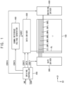
- FIG. 1 is a schematic block diagram illustrating a display apparatus according to an embodiment of the inventive concept.
- the display apparatus includes a display panel 100 and a display panel driver.
- the display panel driver includes a driving controller 200, a gate driver 300, a gamma reference voltage generator 400, a data driver 500 and an emission driver 600.
- the display panel 100 has a display region on which an image may be displayed and a peripheral region adjacent to the display region.
- the display panel 100 includes multiple gate lines GIL, GW1L, GW2L, GW3L and GW4L, multiple data lines DL, multiple emission lines EM1L and EM2L and multiple pixels electrically connected to the gate lines GIL, GW1L, GW2L, GW3L and GW4L, the data lines DL and the emission lines EM1L and EM2L.
- the gate lines GIL, GW1L, GW2L, GW3L and GW4L may extend in a first direction D1
- the data lines DL may extend in a second direction D2 intersecting the first direction D1
- the emission lines EM1L and EM2L may extend in the first direction D1.
- the driving controller 200 receives input image data IMG and an input control signal CONT from an external apparatus.
- the input image data IMG may include red image data, green image data and blue image data.
- the input image data IMG may include white image data.
- the input image data IMG may include magenta image data, cyan image data and yellow image data.
- the input control signal CONT may include a master clock signal and a data enable signal.
- the input control signal CONT may further include a vertical synchronizing signal and a horizontal synchronizing signal.
- the driving controller 200 generates a first control signal CONT1, a second control signal CONT2, a third control signal CONT3, a fourth control signal CONT4 and a data signal DATA based on the input image data IMG and the input control signal CONT.
- the driving controller 200 generates the first control signal CONT1 for controlling an operation of the gate driver 300 based on the input control signal CONT, and outputs the first control signal CONT1 to the gate driver 300.
- the first control signal CONT1 may include a vertical start signal and a gate clock signal.
- the driving controller 200 generates the second control signal CONT2 for controlling an operation of the data driver 500 based on the input control signal CONT, and outputs the second control signal CONT2 to the data driver 500.
- the second control signal CONT2 may include a horizontal start signal and a load signal.
- the driving controller 200 generates the data signal DATA based on the input image data IMG.
- the driving controller 200 outputs the data signal DATA to the data driver 500.
- the driving controller 200 generates the third control signal CONT3 for controlling an operation of the gamma reference voltage generator 400 based on the input control signal CONT, and outputs the third control signal CONT3 to the gamma reference voltage generator 400.
- the driving controller 200 generates the fourth control signal CONT4 for controlling an operation of the emission driver 600 based on the input control signal CONT, and outputs the fourth control signal CONT4 to the emission driver 600.
- the gate driver 300 generates gate signals driving the gate lines GIL, GW1L, GW2L, GW3L and GW4L in response to the first control signal CONT1 received from the driving controller 200.
- the gate driver 300 may output the gate signals to the gate lines GIL, GW1L, GW2L, GW3L and GW4L.
- the gate signals may include a data initialization gate signal, a first writing gate signal, a second writing gate signal, a third writing gate signal and a fourth writing gate signal.
- the gate driver 300 may be illustrated as a single element in FIG. 1 , the inventive concept may not be limited thereto.
- the gate signals may be outputted from plural gate driving circuits respectively.
- the gate driver 300 may be integrated on the peripheral region of the display panel 100. In an embodiment of the inventive concept, the gate driver 300 may be mounted on the peripheral region of the display panel 100.
- the gamma reference voltage generator 400 generates a gamma reference voltage VGREF in response to the third control signal CONT3 received from the driving controller 200.
- the gamma reference voltage generator 400 provides the gamma reference voltage VGREF to the data driver 500.
- the gamma reference voltage VGREF has a value corresponding to a level of the data signal DATA.
- the gamma reference voltage generator 400 may be disposed in the driving controller 200, or in the data driver 500.
- the data driver 500 receives the second control signal CONT2 and the data signal DATA from the driving controller 200, and receives the gamma reference voltages VGREF from the gamma reference voltage generator 400.
- the data driver 500 converts the data signal DATA into data voltages having an analog type using the gamma reference voltages VGREF.
- the data driver 500 outputs the data voltages to the data lines DL.
- the data driver 500 may be integrated on the peripheral region of the display panel 100. In an embodiment of the inventive concept, the data driver 500 may be mounted on the peripheral region of the display panel 100.
- the emission driver 600 generates emission signals to drive the emission lines EM1L and EM2L in response to the fourth control signal CONT4 received from the driving controller 200.
- the emission driver 600 may output the emission signals to the emission lines EM1L and EM2L.
- the emission signals may include a first emission signal and a second emission signal.
- the emission driver 600 may be integrated on the peripheral region of the display panel 100. In an embodiment of the inventive concept, the emission driver 600 may be mounted on the peripheral region of the display panel 100.
- the gate driver 300 may be illustrated to be disposed at a first side of the display panel 100 and the emission driver 600 may be illustrated to be disposed at a second side of the display panel 100 opposite to the first side in FIG. 1 for convenience of explanation, the inventive concept may not be limited thereto.
- both of the gate driver 300 and the emission driver 600 may be disposed at the first side of the display panel 100.
- both of the gate driver 300 and the emission driver 600 may be disposed at both sides of the display panel 100.
- the gate driver 300 and the emission driver 600 may be integral with each other.
- FIG. 2 is a schematic diagram of an equivalent circuit of a pixel of the display panel 100 of FIG. 1 .
- FIG. 3 is a schematic timing diagram illustrating an example of input signals applied to the pixel circuit of FIG. 2 and node signals of the pixel circuit of FIG. 2 .
- the pixel circuit includes a first circuit PC, a second circuit CC and a light emitting element EE.
- the first circuit PC may be a pulse width modulation circuit for a pulse width modulation (PWM).
- the second circuit CC may be a constant current generation circuit for a constant current generation (CCG).
- the first circuit PC may include first to fifth transistors T1, T2, T3, T4 and T5 and a first capacitor C1.
- the second circuit CC may include sixth to eleventh transistors T6, T7, T8, T9, T10 and T11 and a second capacitor C2.
- the light emitting element EE may be a light emitting diode.
- the light emitting element EE may be a micro light emitting diode.
- the pixel circuit may include a first transistor T1 including a control electrode electrically connected to a first node N1, a first electrode electrically connected to a second node N2 and a second electrode electrically connected to a third node N3, a second transistor T2 applying a first data voltage VPWM to the first transistor T1, a third transistor T3 connecting the first node N1 and the third node N3, a sixth transistor T6 including a control electrode electrically connected to a fourth node N4, a first electrode electrically connected to a fifth node N5 and a second electrode electrically connected to a sixth node N6, a seventh transistor T7 applying a second data voltage VCCG to the sixth transistor T6, an eighth transistor T8 connecting the fourth node N4 and the sixth node N6 and the light emitting element EE that emits light based on the first data voltage VPWM and the second data voltage VCCG.
- the third transistor T3 may include a control electrode receiving a third writing gate signal GW3[n], a first electrode electrically connected to the first node N1 and a second electrode electrically connected to the third node N3.
- the seventh transistor T7 may include a control electrode receiving a second writing gate signal GW2, a first electrode receiving the second data voltage VCCG and a second electrode electrically connected to the fifth node N5.
- the eighth transistor T8 may include a control electrode receiving a fourth writing gate signal GW4, a first electrode electrically connected to the fourth node N4 and a second electrode electrically connected to the sixth node N6.
- the light emitting element EE may include an anode electrode NA and a cathode electrode.
- the cathode electrode may receive a third power voltage VSS.
- the pixel circuit may further include a first capacitor C1 including a first electrode receiving a sweep signal SWEEP and a second electrode electrically connected to the first node N1, a second capacitor C2 including a first electrode receiving a second power voltage VDD_CCG and a second electrode electrically connected to the fourth node N4, a fourth transistor T4 including a control electrode receiving a first emission signal EM1, a first electrode receiving a first power voltage VDD_PWM and a second electrode electrically connected to the second node N2, a fifth transistor T5 including a control electrode receiving a second emission signal EM2, a first electrode electrically connected to the third node N3 and a second electrode electrically connected to the fourth node N4, a ninth transistor T9 including a control electrode receiving the first emission signal EM1, a first electrode receiving the second power voltage VDD_CCG and a second electrode electrically connected to the fifth node N5, a tenth transistor T10 including a control electrode receiving the second emission signal EM2, a first electrode electrically connected to the
- the pixel circuit may include eleven transistors and two capacitors.
- the first electrode of the second transistor T2 may be electrically connected to a data voltage terminal VDATA.
- the first electrode of the seventh transistor T7 may be electrically connected to the data voltage terminal VDATA.
- the first data voltage VPWM applied to the first electrode of the second transistor T2 and the second data voltage VCCG applied to the first electrode of the seventh transistor T7 may be outputted from the same voltage terminal so that the pixel circuit may be simplified and the number of voltage lines may decrease.
- the first data voltage VPWM may have the same or different voltage levels according to a light emitting intensity of each pixel.
- the second data voltage VCCG may have the same voltage level for all of the pixels.
- the second data voltage VCCG may have a first voltage level for a red pixel, a second voltage level different from the first voltage level for a green pixel and a third voltage level different from the first voltage level and the second voltage level for a blue pixel.
- the first power voltage VDD_PWM and the second power voltage VDD_CCG may be high power voltages for determining a light emitting degree of the light emitting element EE.
- the third power voltage VSS may be a low power voltage for determining the light emitting degree of the light emitting element EE.
- the first power voltage VDD_PWM and the second power voltage VDD_CCG may be greater than the third power voltage VSS.
- the first power voltage VDD_PWM may be greater than the second power voltage VDD_CCG.
- the sixth transistor T6 is turned on, the light emitting element EE may emit light.
- the first transistor T1 is turned on, the first power voltage VDD_PWM is applied to the control electrode of the sixth transistor T6.
- the sixth transistor T6 may be turned off so that the light emitting element EE stops emitting the light.
- the sixth transistor T6 may be maintained in a turned-off state more reliably.
- the initialization voltage VINT may initialize the anode electrode NA, the control electrode of the first transistor T1 and the control electrode of the sixth transistor T6.
- the light emitting element EE may be turned off.
- the first transistor T1 may be turned on.
- the initialization voltage VINT is applied to the control electrode of the sixth transistor T6, the sixth transistor T6 may be turned on.
- the first writing gate signal GW1[n] and the third writing gate signal GW3[n] may be progressive scan signals having different timings for pixel rows.
- [n] means an n-th pixel row.
- the pixel circuit of FIG. 2 receiving the first writing gate signal GW1[n] and the third writing gate signal GW3[n] may be included in the n-th pixel row.
- the initialization gate signal GI, the second writing gate signal GW2 and the fourth writing gate signal GW4 may be global scan signals having the same timing regardless of the pixel rows.
- the first emission signal EM1 and the second emission signal EM2 may be global scan signals having the same timing regardless of the pixel rows.
- a first pulse of the third writing gate signal GW3[n] may be a global scan pulse having the same timing regardless of the pixel row and a second pulse of the third writing gate signal GW3[n] may be a progressive scan pulse having a different timing according to the pixel row.
- the fifth transistor T5 may be electrically connected to the third node N3 and the fourth node N4.
- the tenth transistor T10 may be electrically connected to the sixth node N6 and the anode electrode NA of the light emitting element EE.
- the eleventh transistor T11 may apply the initialization voltage VINT to the anode electrode NA.
- some of the transistors in the pixel circuit may be P-type transistors and some of the transistors in the pixel circuit may be N-type transistors.
- the P-type transistor may be a low temperature polycrystalline silicon (LTPS) transistor.
- the N-type transistor may be an oxide semiconductor transistor.
- the first transistor T1, the second transistor T2, the sixth transistor T6 and the seventh transistor T7 may be P-type transistors.
- the third transistor T3 and the eighth transistor T8 may be N-type transistors.
- the third transistor T3 is an N-type transistor, a current leakage of the third transistor T3 may be reduced so that the level of the first data voltage VPWM applied to the control electrode of the first transistor T1 may be reliably maintained.
- the eighth transistor T8 is an N-type transistor, a current leakage of the eighth transistor T8 may be reduced so that the level of the second data voltage VCCG applied to the control electrode of the sixth transistor T6 may be reliably maintained.
- the eleventh transistor T11 may be an N-type transistor. In case that the eleventh transistor T11 is an N-type transistor, the initialization performance of the anode electrode NA may be enhanced.
- the fourth transistor T4, the fifth transistor T5, the ninth transistor T9 and the tenth transistor T10 may be P-type transistors.
- a first period DR1 may be an initialization period
- a second period DR2 may be a pulse width modulation data writing and compensation period
- a third period DR3 may be a constant current generation data writing and compensation period
- a fourth period DR4 may be a light emission period
- a fifth period DR5 may be a light emission off period.
- a width of the fourth period DR4 which may be the light emission period may be determined by a level of the pulse width modulation data VPWM.
- the sweep signal SWEEP may have a uniform level in the first period DR1, the second period DR2 and the third period DR3.
- the sweep signal SWEEP may gradually decrease in the fourth period DR4 and the fifth period DR5.
- FIG. 4 is a schematic diagram of an equivalent circuit of a pixel of FIG. 2 in the first period DR1 of a timing diagram.
- FIG. 5 is a schematic timing diagram illustrating an example of input signals applied to the pixel circuit of FIG. 2 and node signals of the pixel circuit of FIG. 2 in the first period DR1.
- FIG. 6 is a schematic diagram of an equivalent circuit of a pixel of FIG. 2 in the second period DR2 of the timing diagram.
- FIG. 7 is a schematic timing diagram illustrating an example of input signals applied to the pixel circuit of FIG. 2 and node signals of the pixel circuit of FIG. 2 in the second period DR2.
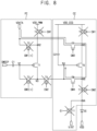
- FIG. 8 is a schematic diagram of an equivalent circuit of a pixel of FIG. 2 in the third period DR3 of the timing diagram.
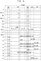
- FIG. 9 is a schematic timing diagram illustrating an example of input signals applied to the pixel circuit of FIG. 2 and node signals of the pixel circuit of FIG. 2 in the third period DR3.
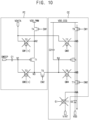
- FIG. 10 is a schematic diagram of an equivalent circuit of a pixel of FIG. 2 in the fourth period DR4 of the timing diagram.
- FIG. 11 is a schematic timing diagram illustrating an example of input signals applied to the pixel circuit of FIG. 2 and node signals of the pixel circuit of FIG. 2 in the fourth period DR4.
- FIG. 12 is a schematic diagram of an equivalent circuit of a pixel of FIG. 2 in the fifth period DR5 of the timing diagram.
- FIG. 13 is a schematic timing diagram illustrating an example of input signals applied to the pixel circuit of FIG. 2 and node signals of the pixel circuit of FIG. 2 in the fifth period DR5.
- the initialization gate signal GI may have an active level
- the first writing gate signal GW1[n] may have an inactive level
- the second writing gate signal GW2 may have an inactive level
- the third writing gate signal GW3[n] may have an active level
- the fourth writing gate signal GW4 may have an active level
- the first emission signal EM1 may have an inactive level
- the second emission signal EM2 may have an active level
- the sweep signal SWEEP may have a first level which may be a fixed level.
- the transistor receiving the initialization gate signal GI, the first writing gate signal GW1[n], the second writing gate signal GW2, the third writing gate signal GW3[n], the fourth writing gate signal GW4, the first emission signal EM1 and the second emission signal EM2 may be a P-type transistor, the active level may be a low level and the inactive level may be a high level.
- the transistor receiving the initialization gate signal GI the first writing gate signal GW1[n], the second writing gate signal GW2, the third writing gate signal GW3[n], the fourth writing gate signal GW4, the first emission signal EM1 and the second emission signal EM2 may be an N-type transistor, the active level may be a high level and the inactive level may be a low level.
- the first period DR1 may be an initialization period.
- the third transistor T3, the fifth transistor T5, the eighth transistor T8, the tenth transistor T10 and the eleventh transistor T11 may be turned on.
- the anode electrode NA may be initialized to the initialization voltage VINT through the eleventh transistor T11.
- the control electrode N4 of the sixth transistor T6 may be initialized to the initialization voltage VINT through a path of the eleventh transistor T11, the tenth transistor T10 and the eighth transistor T8.
- the control electrode N1 of the first transistor T1 may be initialized to the initialization voltage VINT through a path of the eleventh transistor T11, the tenth transistor T10, the eighth transistor T8, the fifth transistor T5 and the third transistor T3.
- the initialization gate signal GI may have an inactive level
- the first writing gate signal GW1[n] may have an active pulse
- the second writing gate signal GW2 may have the inactive level
- the third writing gate signal GW3[n] may have an active pulse
- the fourth writing gate signal GW4 may have an inactive level
- the first emission signal EM1 may have the inactive level
- the second emission signal EM2 may have an inactive level
- the sweep signal SWEEP may have the first level.
- the second period DR2 may be a pulse width modulation data writing and compensation period.
- the second transistor T2 may be turned on by the first writing gate signal GW1[n]
- the first transistor T1 may be turned on by the initialization voltage VINT from the initialization period DR1
- the third transistor T3 may be turned on by the third writing gate signal GW3[n].
- the first data voltage VPWM may be applied to the control electrode of the first transistor T1 through a path of the second transistor T2, the first transistor T1 and the third transistor T3.
- the threshold voltage VTH1 of the first transistor T1 may be compensated in the first data voltage VPWM by the third transistor T3 which may be diode-connected.
- the initialization gate signal GI may have the inactive level
- the first writing gate signal GW1[n] may have the inactive level
- the second writing gate signal GW2 may have an active level
- the third writing gate signal GW3[n] may have an inactive level
- the fourth writing gate signal GW4 may have the active level
- the first emission signal EM1 may have the inactive level
- the second emission signal EM2 may have an inactive level
- the sweep signal SWEEP may have the first level.
- the third period DR3 may be a constant current generation data writing and compensation period.
- the seventh transistor T7 may be turned on by the second writing gate signal GW2
- the sixth transistor T6 may be turned on by the initialization voltage VINT from the initialization period DR1
- the eighth transistor T8 may be turned on by the fourth writing gate signal GW4.
- the second data voltage VCCG may be applied to the control electrode of the sixth transistor T6 through a path of the seventh transistor T7, the sixth transistor T6 and the eighth transistor T8.
- the threshold voltage VTH6 of the sixth transistor T6 may be compensated in the second data voltage VCCG by the eighth transistor T8 which may be diode-connected.
- the initialization gate signal GI may have the inactive level
- the first writing gate signal GW1[n] may have the inactive level
- the second writing gate signal GW2 may have the inactive level
- the third writing gate signal GW3[n] may have the inactive level
- the fourth writing gate signal GW4 may have the inactive level
- the first emission signal EM1 may have an active level
- the second emission signal EM2 may have the active level
- the sweep signal SWEEP may gradually decrease from the first level.
- the fourth period DR4 may be a light emission period.
- the ninth transistor T9 may be turned on by the first emission signal EM1
- the sixth transistor T6 may be turned on by the second data voltage VCCG
- the tenth transistor T10 may be turned on by the second emission signal EM2.
- a current IEE may flow through a path of the ninth transistor T9, the sixth transistor T6, the tenth transistor T10 and the light emitting element EE so that the light emitting element EE may emit light.
- the initialization gate signal GI may have the inactive level
- the first writing gate signal GW1[n] may have the inactive level
- the second writing gate signal GW2 may have the inactive level
- the third writing gate signal GW3[n] may have the inactive level
- the fourth writing gate signal GW4 may have the inactive level
- the first emission signal EM1 may have the active level
- the second emission signal EM2 may have the active level
- the sweep signal SWEEP may gradually decrease.
- the fifth period DR5 may be the light emission off period.
- the first transistor T1 may be turned on at a specific time point.
- the turn-on time point may be determined by the first data voltage VPWM applied to the control electrode of the first transistor T1.
- the first power voltage VDD_PWM may be applied to the control electrode of the sixth transistor T6 along a path of the fourth transistor T4, the first transistor T1 and the fifth transistor T5.
- the sixth transistor T6 is turned off so that the light emitting current IEE stops so that the light emitting element EE stops emitting light.
- the pixel circuit may include eleven transistors and two capacitors.
- the pixel circuit may be driven according to the pulse width modulation technique, operate the internal compensation of the threshold voltage and include the relatively fewer transistors compared to the earlier pixel circuit, so that the high integration may be achieved.
- the pixel circuit may be applicable to an ultra-high resolution display apparatus.
- the control electrode of the first transistor T1, the control electrode of the sixth transistor T6 and the anode electrode NA of the light emitting element EE may be initialized in the initialization period DR1 so that the number of the transistors for the initialization may decrease and the time for initialization may be reduced.
- FIG. 14 is a schematic diagram of an equivalent circuit of a pixel of a display panel 100 of a display apparatus according to an embodiment of the inventive concept.
- the pixel circuit according to the embodiment may be substantially the same as the pixel circuit of the previous embodiment explained referring to FIG. 2 except that a first data voltage terminal applying a first data voltage and a second data voltage terminal applying a second data voltage may be separated.
- a first data voltage terminal applying a first data voltage and a second data voltage terminal applying a second data voltage may be separated.
- the pixel circuit includes a first transistor T1 including a control electrode electrically connected to a first node N1, a first electrode electrically connected to a second node N2 and a second electrode electrically connected to a third node N3, a second transistor T2 applying a first data voltage VPWM to the first transistor T1, a third transistor T3 electrically connected to the first node N1 and the third node N3, a sixth transistor T6 including a control electrode electrically connected to a fourth node N4, a first electrode electrically connected to a fifth node N5 and a second electrode electrically connected to a sixth node N6, a seventh transistor T7 applying a second data voltage VCCG to the sixth transistor T6, an eighth transistor T8 electrically connected to the fourth node N4 and the sixth node N6 and a light emitting element EE emitting a light based on the first data voltage VPWM and the second data voltage VCCG.
- a first electrode of the second transistor T2 may be electrically connected to a first data voltage terminal VDATA.
- a first electrode of the seventh transistor T7 may be electrically connected to a second data voltage terminal VCCG different from the first data voltage terminal VDATA.
- the data voltage terminal applying the first data voltage VPWM and the data voltage terminal applying the second data voltage VCCG may be separated so that a load of an amplifier of the data driver 500 and the power consumption of the data driver 500 may be reduced.
- the pixel circuit may include eleven transistors and two capacitors.
- the pixel circuit may be driven according to the pulse width modulation technique, operate the internal compensation of the threshold voltage and include the relatively fewer transistors compared to the earlier pixel circuit, so that the high integration may be achieved.
- the pixel circuit may be applicable to an ultra-high resolution display apparatus.
- the control electrode of the first transistor T1, the control electrode of the sixth transistor T6 and the anode electrode NA of the light emitting element EE may be initialized in the initialization period DR1 so that the number of the transistors for the initialization may decrease and the time for initialization may be reduced.
- FIG. 15 is a schematic diagram of an equivalent circuit of a pixel of a display panel 100 of a display apparatus according to an embodiment of the inventive concept.
- the pixel circuit according to the embodiment may be substantially the same as the pixel circuit of the previous embodiment explained referring to FIG. 2 except that the third transistor T3, the eighth transistor T8 and the eleventh transistor T11 may be P-type transistors.
- the timing diagram of the signals applied to the pixel circuit according to the embodiment may be substantially the same as the schematic timing diagram of FIG. 3 except that the active levels and the inactive levels of the control signals of the third transistor T3, the eighth transistor T8 and the eleventh transistor T11 may be inverted from the active levels and the inactive levels of the control signals of the third transistor T3, the eighth transistor T8 and the eleventh transistor T11 of FIG. 3 .
- the same reference numerals will be used to refer to the same or like parts as those described in the previous embodiment and any repetitive explanation concerning the above elements will be omitted.
- the pixel circuit includes a first transistor T1 including a control electrode electrically connected to a first node N1, a first electrode electrically connected to a second node N2 and a second electrode electrically connected to a third node N3, a second transistor T2 applying a first data voltage VPWM to the first transistor T1, a third transistor T3 electrically connected to the first node N1 and the third node N3, a sixth transistor T6 including a control electrode electrically connected to a fourth node N4, a first electrode electrically connected to a fifth node N5 and a second electrode electrically connected to a sixth node N6, a seventh transistor T7 applying a second data voltage VCCG to the sixth transistor T6, an eighth transistor T8 electrically connected to the fourth node N4 and the sixth node N6 and a light emitting element EE emitting a light based on the first data voltage VPWM and the second data voltage VCCG.
- the first transistor T1, the second transistor T2, the third transistor T3, the sixth transistor T6, the seventh transistor T7 and the eighth transistor T8 may be P-type transistors.
- the eleventh transistor T11 may be a P-type transistor.
- the fourth transistor T4, the fifth transistor T5, the ninth transistor T9 and the tenth transistor T10 may be P-type transistors.
- all of the transistors in the pixel circuit may be P-type transistors.
- a manufacturing process may be simplified and a manufacturing cost may be reduced.
- the pixel circuit may include eleven transistors and two capacitors.
- the pixel circuit may be driven according to the pulse width modulation technique, operate the internal compensation of the threshold voltage and include the relatively fewer transistors compared to the earlier pixel circuit, so that the high integration may be achieved.
- the pixel circuit may be applicable to an ultra-high resolution display apparatus.
- the control electrode of the first transistor T1, the control electrode of the sixth transistor T6 and the anode electrode NA of the light emitting element EE may be initialized in the initialization period DR1 so that the number of the transistors for the initialization may decrease and the time for initialization may be reduced.
- FIG. 16 is a schematic diagram of an equivalent circuit of a pixel of a display panel 100 of a display apparatus according to an embodiment of the inventive concept.
- the pixel circuit according to the embodiment may be substantially the same as the pixel circuit of the previous embodiment explained referring to FIG. 2 except that the eighth transistor T8 and the eleventh transistor T11 may be P-type transistors.
- the timing diagram of the signals applied to the pixel circuit according to the embodiment may be substantially the same as the timing diagram of FIG. 3 except that the active levels and the inactive levels of the control signals of the eighth transistor T8 and the eleventh transistor T11 may be inverted from the active levels and the inactive levels of the control signals of the eighth transistor T8 and the eleventh transistor T11 of FIG. 3 .
- the same reference numerals will be used to refer to the same or like parts as those described in the previous embodiment and any repetitive explanation concerning the above elements will be omitted.
- the pixel circuit includes a first transistor T1 including a control electrode electrically connected to a first node N1, a first electrode electrically connected to a second node N2 and a second electrode electrically connected to a third node N3, a second transistor T2 applying a first data voltage VPWM to the first transistor T1, a third transistor T3 electrically connected to the first node N1 and the third node N3, a sixth transistor T6 including a control electrode electrically connected to a fourth node N4, a first electrode electrically connected to a fifth node N5 and a second electrode electrically connected to a sixth node N6, a seventh transistor T7 applying a second data voltage VCCG to the sixth transistor T6, an eighth transistor T8 electrically connected to the fourth node N4 and the sixth node N6 and a light emitting element EE that emits light based on the first data voltage VPWM and the second data voltage VCCG.
- a first transistor T1 including a control electrode electrically connected to a first node N1,
- some of the transistors in the pixel circuit may be P-type transistors and some of the transistors in the pixel circuit may be N-type transistors.
- the P-type transistor may be a low temperature polycrystalline silicon (LTPS) transistor.
- the N-type transistor may be an oxide semiconductor transistor.
- the first transistor T1, the second transistor T2, the sixth transistor T6, the seventh transistor T7 and the eighth transistor T8 may be P-type transistors.
- the eleventh transistor T11 may be a P-type transistor.
- the fourth transistor T4, the fifth transistor T5, the ninth transistor T9 and the tenth transistor T10 may be P-type transistors.
- the third transistor T3 may be an N-type transistor.
- almost all of the transistors in the pixel circuit may be P-type transistors.
- a manufacturing cost may be reduced.
- the third transistor T3 is an N-type transistor, a current leakage of the third transistor T3 may be reduced so that a level of the first data voltage VPWM applied to the control electrode of the first transistor T1 may be well maintained.
- the pixel circuit may include eleven transistors and two capacitors.
- the pixel circuit may be driven according to the pulse width modulation technique, operate the internal compensation of the threshold voltage and include the relatively fewer transistors compared to the earlier pixel circuit, so that the high integration may be achieved.
- the pixel circuit may be applicable to an ultra-high resolution display apparatus.
- the control electrode of the first transistor T1, the control electrode of the sixth transistor T6 and the anode electrode NA of the light emitting element EE may be initialized in the initialization period DR1 so that the number of the transistors for the initialization may decrease and the time for initialization may be reduced.
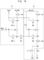
- FIG. 17 is a schematic diagram of an equivalent circuit of a pixel of a display panel of a display apparatus according to an embodiment of the inventive concept.
- the pixel circuit according to the embodiment may be substantially the same as the pixel circuit of the previous embodiment explained referring to FIG. 2 except that the eighth transistor T8 may be a P-type transistor.
- the timing diagram of the signals applied to the pixel circuit according to the embodiment may be substantially the same as the timing diagram of FIG. 3 except that the active level and the inactive level of the control signal of the eighth transistor T8 may be inverted from the active level and the inactive level of the control signal of the eighth transistor T8 of FIG. 3 .
- the same reference numerals will be used to refer to the same or like parts as those described in the previous embodiment and any repetitive explanation concerning the above elements will be omitted.
- the pixel circuit includes a first transistor T1 including a control electrode electrically connected to a first node N1, a first electrode electrically connected to a second node N2 and a second electrode electrically connected to a third node N3, a second transistor T2 applying a first data voltage VPWM to the first transistor T1, a third transistor T3 electrically connected to the first node N1 and the third node N3, a sixth transistor T6 including a control electrode electrically connected to a fourth node N4, a first electrode electrically connected to a fifth node N5 and a second electrode electrically connected to a sixth node N6, a seventh transistor T7 applying a second data voltage VCCG to the sixth transistor T6, an eighth transistor T8 electrically connected to the fourth node N4 and the sixth node N6 and a light emitting element EE that emits light based on the first data voltage VPWM and the second data voltage VCCG.
- a first transistor T1 including a control electrode electrically connected to a first node N1,
- some of the transistors in the pixel circuit may be P-type transistors and some of the transistors in the pixel circuit may be N-type transistors.
- the P-type transistor may be a low temperature polycrystalline silicon (LTPS) transistor.
- the N-type transistor may be an oxide semiconductor transistor.
- the first transistor T1, the second transistor T2, the sixth transistor T6, the seventh transistor T7 and the eighth transistor T8 may be P-type transistors.
- the fourth transistor T4, the fifth transistor T5, the ninth transistor T9 and the tenth transistor T10 may be P-type transistors.
- the third transistor T3 may be an N-type transistor.
- the eleventh transistor T11 may be an N-type transistor.
- almost all of the transistors in the pixel circuit may be P-type transistors.
- a manufacturing cost may be reduced.
- the third transistor T3 is an N-type transistor, a current leakage of the third transistor T3 may be reduced so that a level of the first data voltage VPWM applied to the control electrode of the first transistor T1 may be well maintained.
- the eleventh transistor T11 is an N-type transistor, a performance of an initialization of the anode electrode NA may be improved.
- the pixel circuit may include eleven transistors and two capacitors.
- the pixel circuit may be driven according to the pulse width modulation technique, operate the internal compensation of the threshold voltage and include the relatively fewer transistors compared to the earlier pixel circuit, so that the high integration may be achieved.
- the pixel circuit may be applicable to an ultra-high resolution display apparatus.
- the control electrode of the first transistor T1, the control electrode of the sixth transistor T6 and the anode electrode NA of the light emitting element EE may be initialized in the initialization period DR1 so that the number of the transistors for the initialization may decrease and the time for initialization may be reduced.
- FIG. 18 is a schematic timing diagram illustrating an example of input signals applied to the pixel circuit of FIG. 2 in a first period of the timing diagram.
- the pixel circuit according to the embodiment may be substantially the same as the pixel circuit of the previous embodiment explained referring to FIG. 2 .
- the timing diagram according to the embodiment may be substantially the same as the timing diagram of the previous embodiment explained referring to FIG. 3 except for the initialization period DR1.
- the same reference numerals will be used to refer to the same or like parts as those described in the previous embodiment and any repetitive explanation concerning the above elements will be omitted.
- the pixel circuit includes a first transistor T1 including a control electrode electrically connected to a first node N1, a first electrode electrically connected to a second node N2 and a second electrode electrically connected to a third node N3, a second transistor T2 applying a first data voltage VPWM to the first transistor T1, a third transistor T3 electrically connected to the first node N1 and the third node N3, a sixth transistor T6 including a control electrode electrically connected to a fourth node N4, a first electrode electrically connected to a fifth node N5 and a second electrode electrically connected to a sixth node N6, a seventh transistor T7 applying a second data voltage VCCG to the sixth transistor T6, an eighth transistor T8 electrically connected to the fourth node N4 and the sixth node N6 and a light emitting element EE that emits light based on the first data voltage VPWM and the second data voltage VCCG.
- a first transistor T1 including a control electrode electrically connected to a first node N1,
- the initialization period DR1 may include a first initialization period DA, a second initialization period DB and a third initialization period DC.
- the third transistor T3, the fifth transistor T5, the eighth transistor T8, the tenth transistor T10 and the eleventh transistor T11 may be turned on and the initialization voltage VINT may have a first voltage V1.
- the third transistor T3 may be turned off, the eighth transistor T8, the tenth transistor T10 and the eleventh transistor T11 may remain turned on and the initialization voltage VINT may still have the first voltage V1.
- the third transistor T3, the eighth transistor T8 and the tenth transistor T10 may be turned off, the eleventh transistor T11 may remain turned on and the initialization voltage VINT may have a second voltage V2 different from the first voltage V1.
- the second voltage V2 may be less than the first voltage V1.
- the control electrode of the first transistor T1 may be initialized to the first voltage V1.
- the control electrode of the sixth transistor T6 may be initialized to the first voltage V1.
- the anode electrode NA may be initialized to the second voltage V2.
- the initialization voltages VINT for the first transistor T1, the sixth transistor T6 and the anode electrode NA may be differently set so that the performance of the initialization may be improved.
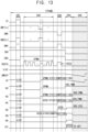
- FIG. 19 is a schematic timing diagram illustrating an example of input signals applied to the pixel circuit of FIG. 2 in a first period of the timing diagram.
- the pixel circuit according to the embodiment may be substantially the same as the pixel circuit of the previous embodiment explained referring to FIG. 2 .
- the timing diagram according to the embodiment may be substantially the same as the timing diagram of the previous embodiment explained referring to FIG. 3 except for the initialization period DR1.
- the same reference numerals will be used to refer to the same or like parts as those described in the previous embodiment and any repetitive explanation concerning the above elements will be omitted.
- the pixel circuit includes a first transistor T1 including a control electrode electrically connected to a first node N1, a first electrode electrically connected to a second node N2 and a second electrode electrically connected to a third node N3, a second transistor T2 applying a first data voltage VPWM to the first transistor T1, a third transistor T3 electrically connected to the first node N1 and the third node N3, a sixth transistor T6 including a control electrode electrically connected to a fourth node N4, a first electrode electrically connected to a fifth node N5 and a second electrode electrically connected to a sixth node N6, a seventh transistor T7 applying a second data voltage VCCG to the sixth transistor T6, an eighth transistor T8 electrically connected to the fourth node N4 and the sixth node N6 and a light emitting element EE that emits light based on the first data voltage VPWM and the second data voltage VCCG.
- a first transistor T1 including a control electrode electrically connected to a first node N1,
- the initialization period DR1 may include a first initialization period DA, a second initialization period DB and a third initialization period DC.
- the third transistor T3, the fifth transistor T5, the eighth transistor T8, the tenth transistor T10 and the eleventh transistor T11 may be turned on and the initialization voltage VINT may have a first voltage V1.
- the third transistor T3 may be turned off, the eighth transistor T8, the tenth transistor T10 and the eleventh transistor T11 may remain turned on and the initialization voltage VINT may have a second voltage V2 different from the first voltage V1.
- the third transistor T3, the eighth transistor T8 and the tenth transistor T10 may be turned off, the eleventh transistor T11 may remain turned on and the initialization voltage VINT may have a third voltage V3 different from the first voltage V1 and the second voltage V2.
- the control electrode of the first transistor T1 may be initialized to the first voltage V1.
- the control electrode of the sixth transistor T6 may be initialized to the second voltage V2.
- the anode electrode NA may be initialized to the third voltage V3.
- the initialization voltages VINT for the first transistor T1, the sixth transistor T6 and the anode electrode NA may be differently set so that the performance of the initialization may be improved.
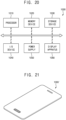
- FIG. 20 is a schematic block diagram illustrating an electronic apparatus according to an embodiment of the inventive concept.
- FIG. 21 is a schematic diagram illustrating an example in which the electronic apparatus of FIG. 20 is implemented as a smart phone.
- the electronic apparatus 1000 may include a processor 1010, a memory device 1020, a storage device 1030, an input/output (I/O) device 1040, a power supply 1050 and a display apparatus 1060.
- the display apparatus 1060 may be the display apparatus of FIG. 1 .
- the electronic apparatus 1000 may further include multiple ports for communicating with a video card, a sound card, a memory card, a universal serial bus (USB) device, other electronic apparatuses, etc.
- USB universal serial bus
- the electronic apparatus 1000 may be implemented as a smart phone 1000'.
- the electronic apparatus 1000 may not be limited thereto.
- the electronic apparatus 1000 may be implemented as a cellular phone, a video phone, a smart pad, a smart watch, a tablet PC, a car navigation system, a computer monitor, a laptop, a head mounted display (HMD) device, and the like.
- HMD head mounted display
- the processor 1010 may perform various computing functions or various tasks.
- the processor 1010 may be a microprocessor, a central processing unit (CPU), an application processor (AP), and the like.
- the processor 1010 may be electrically connected to other components via an address bus, a control bus, a data bus, etc. Further, the processor 1010 may be electrically connected to an extended bus such as a peripheral component interconnection (PCI) bus.
- PCI peripheral component interconnection
- the processor 1010 may output the input image data IMG and the input control signal CONT to the driving controller 200 of FIG. 1 .
- the memory device 1020 may store data for operations of the electronic apparatus 1000.
- the memory device 1020 may include at least one non-volatile memory device such as an erasable programmable read-only memory (EPROM) device, an electrically erasable programmable read-only memory (EEPROM) device, a flash memory device, a phase change random access memory (PRAM) device, a resistance random access memory (RRAM) device, a nano floating gate memory (NFGM) device, a polymer random access memory (PoRAM) device, a magnetic random access memory (MRAM) device, a ferroelectric random access memory (FRAM) device, and the like and/or at least one volatile memory device such as a dynamic random access memory (DRAM) device, a static random access memory (SRAM) device, a mobile DRAM device, and the like.
- DRAM dynamic random access memory
- SRAM static random access memory
- the storage device 1030 may include a solid state drive (SSD) device, a hard disk drive (HDD) device, a CD-ROM device, and the like.
- the I/O device 1040 may include an input device such as a keyboard, a keypad, a mouse device, a touch-pad, a touch-screen, and the like and an output device such as a printer, a speaker, and the like.
- the display apparatus 1060 may be included in the I/O device 1040.
- the power supply 1050 may provide power for operations of the electronic apparatus 1000.
- the display apparatus 1060 may be electrically connected to other components via the buses or other communication links.
- FIG. 22 is a schematic diagram illustrating an example in which the electronic apparatus of FIG. 20 is implemented as a smart watch.
- the electronic apparatus 1000 may be implemented as a smart watch 1000".
- the smart watch 1000" may be an example of the electronic apparatus requiring an ultra-high resolution display panel.
- the ultra-high resolution display apparatus may be implemented using the pixel circuit having the high integration.
Landscapes
- Engineering & Computer Science (AREA)
- Physics & Mathematics (AREA)
- Computer Hardware Design (AREA)
- General Physics & Mathematics (AREA)
- Theoretical Computer Science (AREA)
- Control Of Indicators Other Than Cathode Ray Tubes (AREA)
Abstract
Description
- Embodiments of the disclosure relate to a pixel circuit driven according to a pulse width modulation technique, operating an internal compensation of a threshold voltage, including fewer transistors, and thus, applicable to a ultra-high resolution display apparatus and a display apparatus including the pixel circuit.
- Generally, a display apparatus includes a display panel and a display panel driver. The display panel includes multiple gate lines, multiple data lines, multiple emission lines and multiple pixels. The display panel driver includes a gate driver, a data driver, an emission driver and a driving controller. The gate driver outputs gate signals to the gate lines. The data driver outputs data voltages to the data lines. The emission driver outputs emission signals to the emission lines. The driving controller controls the gate driver, the data driver and the emission driver.
- An earlier pixel circuit driven according to a pulse width modulation technique and operating internal compensation of the threshold voltage may include nineteen or more transistors and three or more capacitors. In case that the pixel circuit includes nineteen or more transistors and three or more capacitors, the pixel circuit may not be applied to an ultra-high resolution display apparatus due to a limitation in integration.
- Embodiments of the inventive concept provide a pixel circuit driven according to a pulse width modulation technique, operating an internal compensation of a threshold voltage, including fewer transistors, and thus, applicable to a ultra-high resolution display apparatus.
- Embodiments of the inventive concept also provide a display apparatus including the pixel circuit.
- In an embodiment of a pixel circuit according to the inventive concept, the pixel circuit may include a first transistor including a control electrode electrically connected to a first node, a first electrode electrically connected to a second node and a second electrode electrically connected to a third node, a second transistor configured to apply a first data voltage to the first transistor, a third transistor electrically connected to the first node and the third node, a fourth transistor including a control electrode electrically connected to a fourth node, a first electrode electrically connected to a fifth node and a second electrode electrically connected to a sixth node, a fifth transistor configured to apply a second data voltage to the fourth transistor, an sixth transistor electrically connected to the fourth node and the sixth node and a light emitting element that emits light based on the first data voltage and the second data voltage.
- The pixel circuit may include a first circuit, a second circuit and the light emitting element.
- The first circuit may include the first to third transistors. The second circuit may include the sixth to eighth transistors.
- The first circuit may be a pulse width modulation circuit for a pulse width modulation. The second circuit may be a constant current generation circuit for a constant current generation.
- In an embodiment, the pixel circuit may further include a first capacitor including a first electrode that receives a sweep signal and a second electrode electrically connected to the first node.
- In an embodiment, the pixel circuit may further include a second capacitor including a first electrode that receives a second power voltage and a second electrode electrically connected to the fourth node.
- In an embodiment, the pixel circuit may further include a seventh transistor electrically connected to the third node and the fourth node, an eighth transistor electrically connected to the sixth node and an anode electrode of the light emitting element and a ninth transistor configured to apply an initialization voltage to the anode electrode.
- In an embodiment, the third transistor, the seventh transistor, the sixth transistor, the eighth transistor and the ninth transistor may be turned on in an initialization period.
- The first circuit may include the first to fifth transistors and the first capacitor. The second circuit may include sixth to eleventh and the second capacitor.
- In an embodiment, the third transistor, the seventh transistor, the sixth transistor, the eighth transistor and the ninth transistor may be turned on and the initialization voltage may have a first voltage in a first initialization period. The third transistor may be turned off, the sixth transistor, the eighth transistor and the ninth transistor may be turned on and the initialization voltage may have the first voltage in a second initialization period subsequent to the first initialization period. The third transistor, the sixth transistor and the eighth transistor may be turned off, the ninth transistor may be turned on and the initialization voltage may have a second voltage different from the first voltage in the third initialization period subsequent to the second initialization period.
- In an embodiment, the second voltage may be less than the first voltage.
- In an embodiment, the third transistor, the seventh transistor, the sixth transistor, the eighth transistor and the ninth transistor may be turned on and the initialization voltage may have a first voltage in a first initialization period. The third transistor may be turned off, the sixth transistor, the eighth transistor and the ninth transistor may be turned on and the initialization voltage may have a second voltage different from the first voltage in a second initialization period subsequent to the first initialization period. The third transistor, the sixth transistor and the eighth transistor may be turned off, the ninth transistor may be turned on and the initialization voltage may have a third voltage different from the first voltage and the second voltage in a third initialization period subsequent to the second initialization period.
- In an embodiment, the first transistor, the second transistor, the fourth transistor and the fifth transistor may be P-type transistors. The third transistor and the sixth transistor may be N-type transistors.
- In an embodiment, the pixel circuit may further include a ninth transistor configured to apply an initialization voltage to an anode electrode of the light emitting element. The ninth transistor may be an N-type transistor.
- In an embodiment, the first transistor, the second transistor, the fourth transistor, the fifth transistor and the sixth transistor may be P-type transistors. The third transistor may be an N-type transistor.
- In an embodiment, the pixel circuit may further include a ninth transistor configured to apply an initialization voltage to an anode electrode of the light emitting element. The ninth transistor may be an N-type transistor.
- In an embodiment, the first transistor, the second transistor, the third transistor, the fourth transistor, the fifth transistor and the sixth transistor may be P-type transistors.
- In an embodiment, the second transistor may include a control electrode that receives a first writing gate signal, a first electrode that receives the first data voltage and a second electrode electrically connected to the second node. The third transistor may include a control electrode that receives a second writing gate signal, a first electrode electrically connected to the first node and a second electrode electrically connected to the third node. The fifth transistor may include a control electrode that receives a third writing gate signal, a first electrode that receives the second data voltage and a second electrode electrically connected to the fifth node. The sixth transistor may include a control electrode that receives a fourth writing gate signal, a first electrode electrically connected to the fourth node and a second electrode electrically connected to the sixth node. The light emitting element may include an anode electrode and a cathode electrode that receives a third power voltage. The pixel circuit may further include a first capacitor including a first electrode that receives a sweep signal and a second electrode electrically connected to the first node, a second capacitor including a first electrode that receives a second power voltage and a second electrode electrically connected to the fourth node, a seventh transistor including a control electrode that receives a first emission signal, a first electrode that receives a first power voltage and a second electrode electrically connected to the second node, an eighth transistor including a control electrode that receives a second emission signal, a first electrode electrically connected to the third node and a second electrode electrically connected to the fourth node, a ninth transistor including a control electrode that receives the first emission signal, a first electrode that receives the second power voltage and a second electrode electrically connected to the fifth node, a tenth transistor including a control electrode that receives the second emission signal, a first electrode electrically connected to the sixth node and a second electrode electrically connected to the anode electrode and an eleventh transistor including a control electrode that receives an initialization gate signal, a first electrode that receives an initialization voltage and a second electrode electrically connected to the anode electrode.
- In an embodiment, the initialization gate signal may have an active level, the first writing gate signal may have an inactive level, the third writing gate signal may have an inactive level, the second writing gate signal may have an active level, the fourth writing gate signal may have an active level, the first emission signal may have an inactive level, the second emission signal may have an active level and the sweep signal may have a first level in a first period.
- In an embodiment, the initialization gate signal may have an inactive level, the first writing gate signal may have an active pulse, the third writing gate signal may have the inactive level, the second writing gate signal may have an active pulse, the fourth writing gate signal may have an inactive level, the first emission signal may have the inactive level, the second emission signal may have an inactive level and the sweep signal may have the first level in a second period subsequent to the first period.
- In an embodiment, the initialization gate signal may have the inactive level, the first writing gate signal may have the inactive level, the third writing gate signal may have an active level, the second writing gate signal may have an inactive level, the fourth writing gate signal may have the active level, the first emission signal may have the inactive level, the second emission signal may have the inactive level and the sweep signal may have the first level in a third period subsequent to the second period.
- In an embodiment, the initialization gate signal may have the inactive level, the first writing gate signal may have the inactive level, the third writing gate signal may have the inactive level, the second writing gate signal may have the inactive level, the fourth writing gate signal may have the inactive level, the first emission signal may have an active level, the second emission signal may have an active level and the sweep signal may gradually decrease from the first level in a fourth period subsequent to the third period.
- In an embodiment, the first power voltage may be greater than the second power voltage.
- In an embodiment, a first electrode of the second transistor may be electrically connected to a data voltage terminal. A first electrode of the fifth transistor may be electrically connected to the data voltage terminal.
- In an embodiment, a first electrode of the second transistor may be electrically connected to a first data voltage terminal. A first electrode of the fifth transistor may be electrically connected to a second data voltage terminal different from the first data voltage terminal.
- In an embodiment of a display apparatus according to the inventive concept, the display apparatus may include a display panel, a gate driver and a data driver. The display panel includes a pixel circuit. The gate driver may be configured to output a gate signal to the pixel circuit. The data driver may be configured to output a data voltage to the pixel circuit. The pixel circuit includes a first transistor including a control electrode electrically connected to a first node, a first electrode electrically connected to a second node and a second electrode electrically connected to a third node, a second transistor configured to apply a first data voltage to the first transistor, a third transistor electrically connected to the first node and the third node, a fourth transistor including a control electrode electrically connected to a fourth node, a first electrode electrically connected to a fifth node and a second electrode electrically connected to a sixth node, a fifth transistor configured to apply a second data voltage to the fourth transistor, an sixth transistor electrically connected to the fourth node and the sixth node and a light emitting element that emits light based on the first data voltage and the second data voltage.
- According to the pixel circuit and the display apparatus including the pixel circuit, the pixel circuit may include eleven transistors and two capacitors. The pixel circuit may be driven according to the pulse width modulation technique, operate the internal compensation of the threshold voltage and include the relatively fewer transistors compared to the earlier pixel circuit, so that the high integration may be achieved. Thus, the pixel circuit may be applicable to an ultra-high resolution display apparatus.
- In a timing diagram of the pixel circuit, the control electrode of the first transistor, the control electrode of the sixth transistor and the anode electrode of the light emitting element may be initialized in the initialization period so that the number of the transistors for the initialization may decrease and the time for initialization may be reduced.
- The above and other features and advantages of the inventive concept will become more apparent by describing in detailed embodiments thereof with reference to the accompanying drawings, in which:
-
FIG. 1 is a schematic block diagram illustrating a display apparatus according to an embodiment of the inventive concept; -
FIG. 2 is a schematic diagram of an equivalent circuit of a pixel of the display panel ofFIG. 1 ; -
FIG. 3 is a schematic timing diagram illustrating an example of input signals applied to the pixel circuit ofFIG. 2 and node signals of the pixel circuit ofFIG. 2 ; -
FIG. 4 is a schematic diagram of an equivalent circuit of a pixel ofFIG. 2 in a first period of a timing diagram; -
FIG. 5 is a schematic timing diagram illustrating an example of input signals applied to the pixel circuit ofFIG. 2 and node signals of the pixel circuit ofFIG. 2 in the first period; -
FIG. 6 is a schematic diagram of an equivalent circuit of a pixel ofFIG. 2 in a second period of the timing diagram; -
FIG. 7 is a schematic timing diagram illustrating an example of input signals applied to the pixel circuit ofFIG. 2 and node signals of the pixel circuit ofFIG. 2 in the second period; -
FIG. 8 is a schematic diagram of an equivalent circuit of a pixel ofFIG. 2 in a third period of the timing diagram; -
FIG. 9 is a schematic timing diagram illustrating an example of input signals applied to the pixel circuit ofFIG. 2 and node signals of the pixel circuit ofFIG. 2 in the third period; -
FIG. 10 is a schematic diagram of an equivalent circuit of a pixel ofFIG. 2 in a fourth period of the timing diagram; -
FIG. 11 is a schematic timing diagram illustrating an example of input signals applied to the pixel circuit ofFIG. 2 and node signals of the pixel circuit ofFIG. 2 in the fourth period; -
FIG. 12 is a schematic diagram of an equivalent circuit of a pixel ofFIG. 2 in a fifth period of the timing diagram; -
FIG. 13 is a schematic timing diagram illustrating an example of input signals applied to the pixel circuit ofFIG. 2 and node signals of the pixel circuit ofFIG. 2 in the fifth period; -
FIG. 14 is a schematic diagram of an equivalent circuit of a pixel of a display panel of a display apparatus according to an embodiment of the inventive concept; -
FIG. 15 is a schematic diagram of an equivalent circuit of a pixel of a display panel of a display apparatus according to an embodiment of the inventive concept; -
FIG. 16 is a schematic diagram of an equivalent circuit of a pixel of a display panel of a display apparatus according to an embodiment of the inventive concept; -
FIG. 17 is a schematic diagram of an equivalent circuit of a pixel of a display panel of a display apparatus according to an embodiment of the inventive concept; -
FIG. 18 is a schematic timing diagram illustrating an example of input signals applied to the pixel circuit ofFIG. 2 in a first period of the timing diagram; -
FIG. 19 is a schematic timing diagram illustrating an example of input signals applied to the pixel circuit ofFIG. 2 in a first period of the timing diagram; -
FIG. 20 is a schematic block diagram illustrating an electronic apparatus according to an embodiment of the inventive concept; -
FIG. 21 is a schematic diagram illustrating an example in which the electronic apparatus ofFIG. 20 is implemented as a smart phone; and -
FIG. 22 is a schematic diagram illustrating an example in which the electronic apparatus ofFIG. 20 is implemented as a smart watch. - In the following description, for the purposes of explanation, numerous specific details are set forth in order to provide a thorough understanding of various embodiments or implementations of the disclosure. As used herein "embodiments" and "implementations" are interchangeable words that are non-limiting examples of devices or methods disclosed herein. It is apparent, however, that various embodiments may be practiced without these specific details or with one or more equivalent arrangements. Here, various embodiments do not have to be exclusive nor limit the disclosure. For example, specific shapes, configurations, and characteristics of an embodiment may be used or implemented in another embodiment.
- Unless otherwise specified, the illustrated embodiments are to be understood as providing features of the disclosure. Therefore, unless otherwise specified, the features, components, modules, layers, films, panels, regions, and/or aspects, etc. (hereinafter individually or collectively referred to as "elements"), of the various embodiments may be otherwise combined, separated, interchanged, and/or rearranged without departing from the inventive concepts.
- The use of cross-hatching and/or shading in the accompanying drawings is generally provided to clarify boundaries between adjacent elements. As such, neither the presence nor the absence of cross-hatching or shading conveys or indicates any preference or requirement for particular materials, material properties, dimensions, proportions, commonalities between illustrated elements, and/or any other characteristic, attribute, property, etc., of the elements, unless specified. Further, in the accompanying drawings, the size and relative sizes of elements may be exaggerated for clarity and/or descriptive purposes. When an embodiment may be implemented differently, a specific process order may be performed differently from the described order. For example, two consecutively described processes may be performed substantially at the same time or performed in an order opposite to the described order. Also, like reference numerals and/or reference characters denote like elements.
- When an element, such as a layer, is referred to as being "on," "connected to," or "coupled to" another element or layer, it may be directly on, connected to, or coupled to the other element or layer or intervening elements or layers may be present. When, however, an element or layer is referred to as being "directly on," "directly connected to," or "directly coupled to" another element or layer, there are no intervening elements or layers present. To this end, the term "connected" may refer to physical, electrical, and/or fluid connection, with or without intervening elements. Further, the X-axis, the Y-axis, and the Z-axis are not limited to three axes of a rectangular coordinate system, such as the x, y, and z axes, and may be interpreted in a broader sense. For example, the X-axis, the Y-axis, and the Z-axis may be perpendicular to one another, or may represent different directions that are not perpendicular to one another.
- For the purposes of this disclosure, "at least one of A and B" may be construed as A only, B only, or any combination of A and B. Also, "at least one of X, Y, and Z" and "at least one selected from the group consisting of X, Y, and Z" may be construed as X only, Y only, Z only, or any combination of two or more of X, Y, and Z. As used herein, the term "and/or" includes any and all combinations of one or more of the associated listed items.
- Although the terms "first," "second," etc. may be used herein to describe various types of elements, these elements should not be limited by these terms. These terms are used to distinguish one element from another element. Thus, a first element discussed below could be termed a second element without departing from the teachings of the disclosure.
- Spatially relative terms, such as "beneath," "below," "under," "lower," "above," "upper," "over," "higher," "side" (e.g., as in "sidewall"), and the like, may be used herein for descriptive purposes, and, thereby, to describe one elements relationship to another element(s) as illustrated in the drawings. Spatially relative terms are intended to encompass different orientations of an apparatus in use, operation, and/or manufacture in addition to the orientation depicted in the drawings. For example, if the apparatus in the drawings is turned over, elements described as "below" or "beneath" other elements or features would then be oriented "above" the other elements or features. Thus, the term "below" can encompass both an orientation of above and below. Furthermore, the apparatus may be otherwise oriented (e.g., rotated 90 degrees or at other orientations), and, as such, the spatially relative descriptors used herein interpreted accordingly.
- The terminology used herein is for the purpose of describing particular embodiments and is not intended to be limiting. As used herein, the singular forms, "a," "an," and "the" are intended to include the plural forms as well, unless the context clearly indicates otherwise. Moreover, the terms "comprises," "comprising," "includes," and/or "including," when used in this specification, specify the presence of stated features, integers, steps, operations, elements, components, and/or groups thereof, but do not preclude the presence or addition of one or more other features, integers, steps, operations, elements, components, and/or groups thereof. It is also noted that, as used herein, the terms "substantially," "about," and other similar terms, are used as terms of approximation and not as terms of degree, and, as such, are utilized to account for inherent deviations in measured, calculated, and/or provided values that would be recognized by one of ordinary skill in the art.
- Various embodiments are described herein with reference to sectional and/or exploded illustrations that are schematic illustrations of embodiments and/or intermediate structures. As such, variations from the shapes of the illustrations as a result, for example, of manufacturing techniques and/or tolerances, are to be expected. Thus, embodiments disclosed herein should not necessarily be construed as limited to the particular illustrated shapes of regions, but are to include deviations in shapes that result from, for instance, manufacturing. In this manner, regions illustrated in the drawings may be schematic in nature and the shapes of these regions may not reflect actual shapes of regions of a device and, as such, are not necessarily intended to be limiting.
- As customary in the field, some embodiments are described and illustrated in the accompanying drawings in terms of functional blocks, units, and/or modules. Those skilled in the art will appreciate that these blocks, units, and/or modules are physically implemented by electronic (or optical) circuits, such as logic circuits, discrete components, microprocessors, hard-wired circuits, memory elements, wiring connections, and the like, which may be formed using semiconductor-based fabrication techniques or other manufacturing technologies. In the case of the blocks, units, and/or modules being implemented by microprocessors or other similar hardware, they may be programmed and controlled using software (e.g., microcode) to perform various functions discussed herein and may optionally be driven by firmware and/or software. It is also contemplated that each block, unit, and/or module may be implemented by dedicated hardware, or as a combination of dedicated hardware to perform some functions and a processor (e.g., one or more programmed microprocessors and associated circuitry) to perform other functions. Also, each block, unit, and/or module of some embodiments may be physically separated into two or more interacting and discrete blocks, units, and/or modules without departing from the scope of the inventive concepts. Further, the blocks, units, and/or modules of some embodiments may be physically combined into more complex blocks, units, and/or modules without departing from the scope of the inventive concepts.
- Unless otherwise defined or implied herein, all terms (including technical and scientific terms) used herein have the same meaning as commonly understood by those skilled in the art to which this disclosure pertains. It will be further understood that terms, such as those defined in commonly used dictionaries, should be interpreted as having a meaning that is consistent with their meaning in the context of the relevant art and the disclosure, and should not be interpreted in an ideal or excessively formal sense unless clearly so defined herein.
- Hereinafter, the inventive concept will be explained in detail with reference to the accompanying drawings.
-
FIG. 1 is a schematic block diagram illustrating a display apparatus according to an embodiment of the inventive concept. - Referring to
FIG. 1 , the display apparatus includes adisplay panel 100 and a display panel driver. The display panel driver includes a drivingcontroller 200, agate driver 300, a gammareference voltage generator 400, adata driver 500 and anemission driver 600. - The
display panel 100 has a display region on which an image may be displayed and a peripheral region adjacent to the display region. - The
display panel 100 includes multiple gate lines GIL, GW1L, GW2L, GW3L and GW4L, multiple data lines DL, multiple emission lines EM1L and EM2L and multiple pixels electrically connected to the gate lines GIL, GW1L, GW2L, GW3L and GW4L, the data lines DL and the emission lines EM1L and EM2L. The gate lines GIL, GW1L, GW2L, GW3L and GW4L may extend in a first direction D1, the data lines DL may extend in a second direction D2 intersecting the first direction D1 and the emission lines EM1L and EM2L may extend in the first direction D1. - The driving
controller 200 receives input image data IMG and an input control signal CONT from an external apparatus. For example, the input image data IMG may include red image data, green image data and blue image data. The input image data IMG may include white image data. The input image data IMG may include magenta image data, cyan image data and yellow image data. The input control signal CONT may include a master clock signal and a data enable signal. The input control signal CONT may further include a vertical synchronizing signal and a horizontal synchronizing signal. - The driving
controller 200 generates a first control signal CONT1, a second control signal CONT2, a third control signal CONT3, a fourth control signal CONT4 and a data signal DATA based on the input image data IMG and the input control signal CONT. - The driving
controller 200 generates the first control signal CONT1 for controlling an operation of thegate driver 300 based on the input control signal CONT, and outputs the first control signal CONT1 to thegate driver 300. The first control signal CONT1 may include a vertical start signal and a gate clock signal. - The driving
controller 200 generates the second control signal CONT2 for controlling an operation of thedata driver 500 based on the input control signal CONT, and outputs the second control signal CONT2 to thedata driver 500. The second control signal CONT2 may include a horizontal start signal and a load signal. - The driving
controller 200 generates the data signal DATA based on the input image data IMG. The drivingcontroller 200 outputs the data signal DATA to thedata driver 500. - The driving
controller 200 generates the third control signal CONT3 for controlling an operation of the gammareference voltage generator 400 based on the input control signal CONT, and outputs the third control signal CONT3 to the gammareference voltage generator 400. - The driving
controller 200 generates the fourth control signal CONT4 for controlling an operation of theemission driver 600 based on the input control signal CONT, and outputs the fourth control signal CONT4 to theemission driver 600. - The
gate driver 300 generates gate signals driving the gate lines GIL, GW1L, GW2L, GW3L and GW4L in response to the first control signal CONT1 received from the drivingcontroller 200. Thegate driver 300 may output the gate signals to the gate lines GIL, GW1L, GW2L, GW3L and GW4L. The gate signals may include a data initialization gate signal, a first writing gate signal, a second writing gate signal, a third writing gate signal and a fourth writing gate signal. Although thegate driver 300 may be illustrated as a single element inFIG. 1 , the inventive concept may not be limited thereto. The gate signals may be outputted from plural gate driving circuits respectively. - In an embodiment of the inventive concept, the
gate driver 300 may be integrated on the peripheral region of thedisplay panel 100. In an embodiment of the inventive concept, thegate driver 300 may be mounted on the peripheral region of thedisplay panel 100. - The gamma
reference voltage generator 400 generates a gamma reference voltage VGREF in response to the third control signal CONT3 received from the drivingcontroller 200. The gammareference voltage generator 400 provides the gamma reference voltage VGREF to thedata driver 500. The gamma reference voltage VGREF has a value corresponding to a level of the data signal DATA. - In an embodiment, the gamma
reference voltage generator 400 may be disposed in the drivingcontroller 200, or in thedata driver 500. - The
data driver 500 receives the second control signal CONT2 and the data signal DATA from the drivingcontroller 200, and receives the gamma reference voltages VGREF from the gammareference voltage generator 400. Thedata driver 500 converts the data signal DATA into data voltages having an analog type using the gamma reference voltages VGREF. Thedata driver 500 outputs the data voltages to the data lines DL. - In an embodiment of the inventive concept, the
data driver 500 may be integrated on the peripheral region of thedisplay panel 100. In an embodiment of the inventive concept, thedata driver 500 may be mounted on the peripheral region of thedisplay panel 100. - The
emission driver 600 generates emission signals to drive the emission lines EM1L and EM2L in response to the fourth control signal CONT4 received from the drivingcontroller 200. Theemission driver 600 may output the emission signals to the emission lines EM1L and EM2L. The emission signals may include a first emission signal and a second emission signal. - In an embodiment of the inventive concept, the
emission driver 600 may be integrated on the peripheral region of thedisplay panel 100. In an embodiment of the inventive concept, theemission driver 600 may be mounted on the peripheral region of thedisplay panel 100. - Although the
gate driver 300 may be illustrated to be disposed at a first side of thedisplay panel 100 and theemission driver 600 may be illustrated to be disposed at a second side of thedisplay panel 100 opposite to the first side inFIG. 1 for convenience of explanation, the inventive concept may not be limited thereto. For example, both of thegate driver 300 and theemission driver 600 may be disposed at the first side of thedisplay panel 100. For example, both of thegate driver 300 and theemission driver 600 may be disposed at both sides of thedisplay panel 100. For example, thegate driver 300 and theemission driver 600 may be integral with each other. -
FIG. 2 is a schematic diagram of an equivalent circuit of a pixel of thedisplay panel 100 ofFIG. 1 .FIG. 3 is a schematic timing diagram illustrating an example of input signals applied to the pixel circuit ofFIG. 2 and node signals of the pixel circuit ofFIG. 2 . - Referring to
FIGS. 1 to 3 , the pixel circuit includes a first circuit PC, a second circuit CC and a light emitting element EE. - The first circuit PC may be a pulse width modulation circuit for a pulse width modulation (PWM). The second circuit CC may be a constant current generation circuit for a constant current generation (CCG).
- The first circuit PC may include first to fifth transistors T1, T2, T3, T4 and T5 and a first capacitor C1. The second circuit CC may include sixth to eleventh transistors T6, T7, T8, T9, T10 and T11 and a second capacitor C2.
- For example, the light emitting element EE may be a light emitting diode. In an embodiment, the light emitting element EE may be a micro light emitting diode.
- The pixel circuit may include a first transistor T1 including a control electrode electrically connected to a first node N1, a first electrode electrically connected to a second node N2 and a second electrode electrically connected to a third node N3, a second transistor T2 applying a first data voltage VPWM to the first transistor T1, a third transistor T3 connecting the first node N1 and the third node N3, a sixth transistor T6 including a control electrode electrically connected to a fourth node N4, a first electrode electrically connected to a fifth node N5 and a second electrode electrically connected to a sixth node N6, a seventh transistor T7 applying a second data voltage VCCG to the sixth transistor T6, an eighth transistor T8 connecting the fourth node N4 and the sixth node N6 and the light emitting element EE that emits light based on the first data voltage VPWM and the second data voltage VCCG.
- The second transistor T2 may include a control electrode receiving a first writing gate signal GW1[n], a first electrode receiving the first data voltage VPWM and a second electrode electrically connected to the second node N2.
- The third transistor T3 may include a control electrode receiving a third writing gate signal GW3[n], a first electrode electrically connected to the first node N1 and a second electrode electrically connected to the third node N3.
- The seventh transistor T7 may include a control electrode receiving a second writing gate signal GW2, a first electrode receiving the second data voltage VCCG and a second electrode electrically connected to the fifth node N5.
- The eighth transistor T8 may include a control electrode receiving a fourth writing gate signal GW4, a first electrode electrically connected to the fourth node N4 and a second electrode electrically connected to the sixth node N6.
- The light emitting element EE may include an anode electrode NA and a cathode electrode. The cathode electrode may receive a third power voltage VSS.
- The pixel circuit may further include a first capacitor C1 including a first electrode receiving a sweep signal SWEEP and a second electrode electrically connected to the first node N1, a second capacitor C2 including a first electrode receiving a second power voltage VDD_CCG and a second electrode electrically connected to the fourth node N4, a fourth transistor T4 including a control electrode receiving a first emission signal EM1, a first electrode receiving a first power voltage VDD_PWM and a second electrode electrically connected to the second node N2, a fifth transistor T5 including a control electrode receiving a second emission signal EM2, a first electrode electrically connected to the third node N3 and a second electrode electrically connected to the fourth node N4, a ninth transistor T9 including a control electrode receiving the first emission signal EM1, a first electrode receiving the second power voltage VDD_CCG and a second electrode electrically connected to the fifth node N5, a tenth transistor T10 including a control electrode receiving the second emission signal EM2, a first electrode electrically connected to the sixth node N6 and a second electrode electrically connected to the anode electrode NA and an eleventh transistor T11 including a control electrode receiving an initialization gate signal GI, a first electrode receiving an initialization voltage VINT and a second electrode electrically connected to the anode electrode NA.
- As explained above, the pixel circuit may include eleven transistors and two capacitors.
- In the embodiment, the first electrode of the second transistor T2 may be electrically connected to a data voltage terminal VDATA. The first electrode of the seventh transistor T7 may be electrically connected to the data voltage terminal VDATA. The first data voltage VPWM applied to the first electrode of the second transistor T2 and the second data voltage VCCG applied to the first electrode of the seventh transistor T7 may be outputted from the same voltage terminal so that the pixel circuit may be simplified and the number of voltage lines may decrease. The first data voltage VPWM may have the same or different voltage levels according to a light emitting intensity of each pixel. The second data voltage VCCG may have the same voltage level for all of the pixels. The second data voltage VCCG may have a first voltage level for a red pixel, a second voltage level different from the first voltage level for a green pixel and a third voltage level different from the first voltage level and the second voltage level for a blue pixel.
- For example, the first power voltage VDD_PWM and the second power voltage VDD_CCG may be high power voltages for determining a light emitting degree of the light emitting element EE. For example, the third power voltage VSS may be a low power voltage for determining the light emitting degree of the light emitting element EE. The first power voltage VDD_PWM and the second power voltage VDD_CCG may be greater than the third power voltage VSS.
- The first power voltage VDD_PWM may be greater than the second power voltage VDD_CCG. In case that the sixth transistor T6 is turned on, the light emitting element EE may emit light. In case that the first transistor T1 is turned on, the first power voltage VDD_PWM is applied to the control electrode of the sixth transistor T6. In case that the first power voltage VDD_PWM is applied to the control electrode of the sixth transistor T6, the sixth transistor T6 may be turned off so that the light emitting element EE stops emitting the light.
- In case that the first power voltage VDD_PWM is greater than the second power voltage VDD_CCG and the first power voltage VDD_PWM may be applied to the control electrode of the sixth transistor T6, the sixth transistor T6 may be maintained in a turned-off state more reliably.
- For example, the initialization voltage VINT may initialize the anode electrode NA, the control electrode of the first transistor T1 and the control electrode of the sixth transistor T6.
- In case that the initialization voltage VINT is applied to the anode electrode NA, the light emitting element EE may be turned off. In case that the initialization voltage VINT is applied to the control electrode of the first transistor T1, the first transistor T1 may be turned on. In case that the initialization voltage VINT is applied to the control electrode of the sixth transistor T6, the sixth transistor T6 may be turned on.
- The first writing gate signal GW1[n] and the third writing gate signal GW3[n] may be progressive scan signals having different timings for pixel rows. Herein, [n] means an n-th pixel row. The pixel circuit of
FIG. 2 receiving the first writing gate signal GW1[n] and the third writing gate signal GW3[n] may be included in the n-th pixel row. - The initialization gate signal GI, the second writing gate signal GW2 and the fourth writing gate signal GW4 may be global scan signals having the same timing regardless of the pixel rows. The first emission signal EM1 and the second emission signal EM2 may be global scan signals having the same timing regardless of the pixel rows.
- A first pulse of the third writing gate signal GW3[n] may be a global scan pulse having the same timing regardless of the pixel row and a second pulse of the third writing gate signal GW3[n] may be a progressive scan pulse having a different timing according to the pixel row.
- The fifth transistor T5 may be electrically connected to the third node N3 and the fourth node N4. The tenth transistor T10 may be electrically connected to the sixth node N6 and the anode electrode NA of the light emitting element EE. The eleventh transistor T11 may apply the initialization voltage VINT to the anode electrode NA.
- In the embodiment, some of the transistors in the pixel circuit may be P-type transistors and some of the transistors in the pixel circuit may be N-type transistors. For example, the P-type transistor may be a low temperature polycrystalline silicon (LTPS) transistor. For example, the N-type transistor may be an oxide semiconductor transistor.
- In the embodiment, the first transistor T1, the second transistor T2, the sixth transistor T6 and the seventh transistor T7 may be P-type transistors. In contrast, the third transistor T3 and the eighth transistor T8 may be N-type transistors.
- In case that the third transistor T3 is an N-type transistor, a current leakage of the third transistor T3 may be reduced so that the level of the first data voltage VPWM applied to the control electrode of the first transistor T1 may be reliably maintained.
- Similarly, in case that the eighth transistor T8 is an N-type transistor, a current leakage of the eighth transistor T8 may be reduced so that the level of the second data voltage VCCG applied to the control electrode of the sixth transistor T6 may be reliably maintained.
- The eleventh transistor T11 may be an N-type transistor. In case that the eleventh transistor T11 is an N-type transistor, the initialization performance of the anode electrode NA may be enhanced.
- The fourth transistor T4, the fifth transistor T5, the ninth transistor T9 and the tenth transistor T10 may be P-type transistors.
- In the timing diagram of
FIG. 3 , a first period DR1 may be an initialization period, a second period DR2 may be a pulse width modulation data writing and compensation period, a third period DR3 may be a constant current generation data writing and compensation period, a fourth period DR4 may be a light emission period and a fifth period DR5 may be a light emission off period. - A width of the fourth period DR4 which may be the light emission period may be determined by a level of the pulse width modulation data VPWM.
- The sweep signal SWEEP may have a uniform level in the first period DR1, the second period DR2 and the third period DR3. The sweep signal SWEEP may gradually decrease in the fourth period DR4 and the fifth period DR5.
-
FIG. 4 is a schematic diagram of an equivalent circuit of a pixel ofFIG. 2 in the first period DR1 of a timing diagram.FIG. 5 is a schematic timing diagram illustrating an example of input signals applied to the pixel circuit ofFIG. 2 and node signals of the pixel circuit ofFIG. 2 in the first period DR1.FIG. 6 is a schematic diagram of an equivalent circuit of a pixel ofFIG. 2 in the second period DR2 of the timing diagram.FIG. 7 is a schematic timing diagram illustrating an example of input signals applied to the pixel circuit ofFIG. 2 and node signals of the pixel circuit ofFIG. 2 in the second period DR2.FIG. 8 is a schematic diagram of an equivalent circuit of a pixel ofFIG. 2 in the third period DR3 of the timing diagram.FIG. 9 is a schematic timing diagram illustrating an example of input signals applied to the pixel circuit ofFIG. 2 and node signals of the pixel circuit ofFIG. 2 in the third period DR3.FIG. 10 is a schematic diagram of an equivalent circuit of a pixel ofFIG. 2 in the fourth period DR4 of the timing diagram.FIG. 11 is a schematic timing diagram illustrating an example of input signals applied to the pixel circuit ofFIG. 2 and node signals of the pixel circuit ofFIG. 2 in the fourth period DR4.FIG. 12 is a schematic diagram of an equivalent circuit of a pixel ofFIG. 2 in the fifth period DR5 of the timing diagram.FIG. 13 is a schematic timing diagram illustrating an example of input signals applied to the pixel circuit ofFIG. 2 and node signals of the pixel circuit ofFIG. 2 in the fifth period DR5. - Referring to
FIGS. 4 and5 , in the first period DR1, the initialization gate signal GI may have an active level, the first writing gate signal GW1[n] may have an inactive level, the second writing gate signal GW2 may have an inactive level, the third writing gate signal GW3[n] may have an active level, the fourth writing gate signal GW4 may have an active level, the first emission signal EM1 may have an inactive level, the second emission signal EM2 may have an active level and the sweep signal SWEEP may have a first level which may be a fixed level. - Herein, in case that the transistor receiving the initialization gate signal GI, the first writing gate signal GW1[n], the second writing gate signal GW2, the third writing gate signal GW3[n], the fourth writing gate signal GW4, the first emission signal EM1 and the second emission signal EM2 may be a P-type transistor, the active level may be a low level and the inactive level may be a high level. In contrast, in case that the transistor receiving the initialization gate signal GI, the first writing gate signal GW1[n], the second writing gate signal GW2, the third writing gate signal GW3[n], the fourth writing gate signal GW4, the first emission signal EM1 and the second emission signal EM2 may be an N-type transistor, the active level may be a high level and the inactive level may be a low level.
- The first period DR1 may be an initialization period. In the initialization period DR1, the third transistor T3, the fifth transistor T5, the eighth transistor T8, the tenth transistor T10 and the eleventh transistor T11 may be turned on.
- The anode electrode NA may be initialized to the initialization voltage VINT through the eleventh transistor T11. The control electrode N4 of the sixth transistor T6 may be initialized to the initialization voltage VINT through a path of the eleventh transistor T11, the tenth transistor T10 and the eighth transistor T8. The control electrode N1 of the first transistor T1 may be initialized to the initialization voltage VINT through a path of the eleventh transistor T11, the tenth transistor T10, the eighth transistor T8, the fifth transistor T5 and the third transistor T3.
- Referring to
FIGS. 6 and7 , in the second period DR2 subsequent to the first period DR1, the initialization gate signal GI may have an inactive level, the first writing gate signal GW1[n] may have an active pulse, the second writing gate signal GW2 may have the inactive level, the third writing gate signal GW3[n] may have an active pulse, the fourth writing gate signal GW4 may have an inactive level, the first emission signal EM1 may have the inactive level, the second emission signal EM2 may have an inactive level and the sweep signal SWEEP may have the first level. - The second period DR2 may be a pulse width modulation data writing and compensation period. In the pulse width modulation data writing and compensation period DR2, the second transistor T2 may be turned on by the first writing gate signal GW1[n], the first transistor T1 may be turned on by the initialization voltage VINT from the initialization period DR1 and the third transistor T3 may be turned on by the third writing gate signal GW3[n].
- In the pulse width modulation data writing and compensation period DR2, the first data voltage VPWM may be applied to the control electrode of the first transistor T1 through a path of the second transistor T2, the first transistor T1 and the third transistor T3. The threshold voltage VTH1 of the first transistor T1 may be compensated in the first data voltage VPWM by the third transistor T3 which may be diode-connected.
- Referring to
FIGS. 8 and9 , in the third period DR3 subsequent to the second period DR2, the initialization gate signal GI may have the inactive level, the first writing gate signal GW1[n] may have the inactive level, the second writing gate signal GW2 may have an active level, the third writing gate signal GW3[n] may have an inactive level, the fourth writing gate signal GW4 may have the active level, the first emission signal EM1 may have the inactive level, the second emission signal EM2 may have an inactive level and the sweep signal SWEEP may have the first level. - The third period DR3 may be a constant current generation data writing and compensation period. In the constant current generation data writing and compensation period DR3, the seventh transistor T7 may be turned on by the second writing gate signal GW2, the sixth transistor T6 may be turned on by the initialization voltage VINT from the initialization period DR1 and the eighth transistor T8 may be turned on by the fourth writing gate signal GW4.
- In the constant current generation data writing and compensation period DR3, the second data voltage VCCG may be applied to the control electrode of the sixth transistor T6 through a path of the seventh transistor T7, the sixth transistor T6 and the eighth transistor T8. The threshold voltage VTH6 of the sixth transistor T6 may be compensated in the second data voltage VCCG by the eighth transistor T8 which may be diode-connected.
- Referring to
FIGS. 10 and11 , in the fourth period DR4 subsequent to the third period DR3, the initialization gate signal GI may have the inactive level, the first writing gate signal GW1[n] may have the inactive level, the second writing gate signal GW2 may have the inactive level, the third writing gate signal GW3[n] may have the inactive level, the fourth writing gate signal GW4 may have the inactive level, the first emission signal EM1 may have an active level, the second emission signal EM2 may have the active level and the sweep signal SWEEP may gradually decrease from the first level. - The fourth period DR4 may be a light emission period. In the light emission period DR4, the ninth transistor T9 may be turned on by the first emission signal EM1, the sixth transistor T6 may be turned on by the second data voltage VCCG and the tenth transistor T10 may be turned on by the second emission signal EM2.
- In the light emission period DR4, a current IEE may flow through a path of the ninth transistor T9, the sixth transistor T6, the tenth transistor T10 and the light emitting element EE so that the light emitting element EE may emit light.
- Referring to
FIGS. 12 and13 , in the fifth period DR5 subsequent to the fourth period DR4, the initialization gate signal GI may have the inactive level, the first writing gate signal GW1[n] may have the inactive level, the second writing gate signal GW2 may have the inactive level, the third writing gate signal GW3[n] may have the inactive level, the fourth writing gate signal GW4 may have the inactive level, the first emission signal EM1 may have the active level, the second emission signal EM2 may have the active level and the sweep signal SWEEP may gradually decrease. - The fifth period DR5 may be the light emission off period. As the sweep signal SWEEP decreases, the first transistor T1 may be turned on at a specific time point. The turn-on time point may be determined by the first data voltage VPWM applied to the control electrode of the first transistor T1.
- In case that the first transistor T1 is turned on, the first power voltage VDD_PWM may be applied to the control electrode of the sixth transistor T6 along a path of the fourth transistor T4, the first transistor T1 and the fifth transistor T5.
- In case that the first power voltage VDD_PWM is applied to the control electrode of the sixth transistor T6, the sixth transistor T6 is turned off so that the light emitting current IEE stops so that the light emitting element EE stops emitting light.
- According to the embodiment, the pixel circuit may include eleven transistors and two capacitors. The pixel circuit may be driven according to the pulse width modulation technique, operate the internal compensation of the threshold voltage and include the relatively fewer transistors compared to the earlier pixel circuit, so that the high integration may be achieved. Thus, the pixel circuit may be applicable to an ultra-high resolution display apparatus.
- In the timing diagram of the pixel circuit, the control electrode of the first transistor T1, the control electrode of the sixth transistor T6 and the anode electrode NA of the light emitting element EE may be initialized in the initialization period DR1 so that the number of the transistors for the initialization may decrease and the time for initialization may be reduced.
-
FIG. 14 is a schematic diagram of an equivalent circuit of a pixel of adisplay panel 100 of a display apparatus according to an embodiment of the inventive concept. - The pixel circuit according to the embodiment may be substantially the same as the pixel circuit of the previous embodiment explained referring to
FIG. 2 except that a first data voltage terminal applying a first data voltage and a second data voltage terminal applying a second data voltage may be separated. Thus, the same reference numerals will be used to refer to the same or like parts as those described in the previous embodiment and any repetitive explanation concerning the above elements will be omitted. - Referring to
FIGS. 1 and3 to 14 , the pixel circuit includes a first transistor T1 including a control electrode electrically connected to a first node N1, a first electrode electrically connected to a second node N2 and a second electrode electrically connected to a third node N3, a second transistor T2 applying a first data voltage VPWM to the first transistor T1, a third transistor T3 electrically connected to the first node N1 and the third node N3, a sixth transistor T6 including a control electrode electrically connected to a fourth node N4, a first electrode electrically connected to a fifth node N5 and a second electrode electrically connected to a sixth node N6, a seventh transistor T7 applying a second data voltage VCCG to the sixth transistor T6, an eighth transistor T8 electrically connected to the fourth node N4 and the sixth node N6 and a light emitting element EE emitting a light based on the first data voltage VPWM and the second data voltage VCCG. - In the embodiment, a first electrode of the second transistor T2 may be electrically connected to a first data voltage terminal VDATA. A first electrode of the seventh transistor T7 may be electrically connected to a second data voltage terminal VCCG different from the first data voltage terminal VDATA.
- The data voltage terminal applying the first data voltage VPWM and the data voltage terminal applying the second data voltage VCCG may be separated so that a load of an amplifier of the
data driver 500 and the power consumption of thedata driver 500 may be reduced. - According to the embodiment, the pixel circuit may include eleven transistors and two capacitors. The pixel circuit may be driven according to the pulse width modulation technique, operate the internal compensation of the threshold voltage and include the relatively fewer transistors compared to the earlier pixel circuit, so that the high integration may be achieved. Thus, the pixel circuit may be applicable to an ultra-high resolution display apparatus.
- In the timing diagram of the pixel circuit, the control electrode of the first transistor T1, the control electrode of the sixth transistor T6 and the anode electrode NA of the light emitting element EE may be initialized in the initialization period DR1 so that the number of the transistors for the initialization may decrease and the time for initialization may be reduced.
-
FIG. 15 is a schematic diagram of an equivalent circuit of a pixel of adisplay panel 100 of a display apparatus according to an embodiment of the inventive concept. - The pixel circuit according to the embodiment may be substantially the same as the pixel circuit of the previous embodiment explained referring to
FIG. 2 except that the third transistor T3, the eighth transistor T8 and the eleventh transistor T11 may be P-type transistors. The timing diagram of the signals applied to the pixel circuit according to the embodiment may be substantially the same as the schematic timing diagram ofFIG. 3 except that the active levels and the inactive levels of the control signals of the third transistor T3, the eighth transistor T8 and the eleventh transistor T11 may be inverted from the active levels and the inactive levels of the control signals of the third transistor T3, the eighth transistor T8 and the eleventh transistor T11 ofFIG. 3 . Thus, the same reference numerals will be used to refer to the same or like parts as those described in the previous embodiment and any repetitive explanation concerning the above elements will be omitted. - Referring to
FIGS. 1 and3 to 13 and15 , the pixel circuit includes a first transistor T1 including a control electrode electrically connected to a first node N1, a first electrode electrically connected to a second node N2 and a second electrode electrically connected to a third node N3, a second transistor T2 applying a first data voltage VPWM to the first transistor T1, a third transistor T3 electrically connected to the first node N1 and the third node N3, a sixth transistor T6 including a control electrode electrically connected to a fourth node N4, a first electrode electrically connected to a fifth node N5 and a second electrode electrically connected to a sixth node N6, a seventh transistor T7 applying a second data voltage VCCG to the sixth transistor T6, an eighth transistor T8 electrically connected to the fourth node N4 and the sixth node N6 and a light emitting element EE emitting a light based on the first data voltage VPWM and the second data voltage VCCG. - In the embodiment, the first transistor T1, the second transistor T2, the third transistor T3, the sixth transistor T6, the seventh transistor T7 and the eighth transistor T8 may be P-type transistors. The eleventh transistor T11 may be a P-type transistor. The fourth transistor T4, the fifth transistor T5, the ninth transistor T9 and the tenth transistor T10 may be P-type transistors.
- As explained above, for example, in the embodiment, all of the transistors in the pixel circuit may be P-type transistors. In case that all of the transistors in the pixel circuit are P-type transistors, a manufacturing process may be simplified and a manufacturing cost may be reduced.
- According to the embodiment, the pixel circuit may include eleven transistors and two capacitors. The pixel circuit may be driven according to the pulse width modulation technique, operate the internal compensation of the threshold voltage and include the relatively fewer transistors compared to the earlier pixel circuit, so that the high integration may be achieved. Thus, the pixel circuit may be applicable to an ultra-high resolution display apparatus.
- In the timing diagram of the pixel circuit, the control electrode of the first transistor T1, the control electrode of the sixth transistor T6 and the anode electrode NA of the light emitting element EE may be initialized in the initialization period DR1 so that the number of the transistors for the initialization may decrease and the time for initialization may be reduced.
-
FIG. 16 is a schematic diagram of an equivalent circuit of a pixel of adisplay panel 100 of a display apparatus according to an embodiment of the inventive concept. - The pixel circuit according to the embodiment may be substantially the same as the pixel circuit of the previous embodiment explained referring to
FIG. 2 except that the eighth transistor T8 and the eleventh transistor T11 may be P-type transistors. The timing diagram of the signals applied to the pixel circuit according to the embodiment may be substantially the same as the timing diagram ofFIG. 3 except that the active levels and the inactive levels of the control signals of the eighth transistor T8 and the eleventh transistor T11 may be inverted from the active levels and the inactive levels of the control signals of the eighth transistor T8 and the eleventh transistor T11 ofFIG. 3 . Thus, the same reference numerals will be used to refer to the same or like parts as those described in the previous embodiment and any repetitive explanation concerning the above elements will be omitted. - Referring to
FIGS. 1 and3 to 13 and16 , the pixel circuit includes a first transistor T1 including a control electrode electrically connected to a first node N1, a first electrode electrically connected to a second node N2 and a second electrode electrically connected to a third node N3, a second transistor T2 applying a first data voltage VPWM to the first transistor T1, a third transistor T3 electrically connected to the first node N1 and the third node N3, a sixth transistor T6 including a control electrode electrically connected to a fourth node N4, a first electrode electrically connected to a fifth node N5 and a second electrode electrically connected to a sixth node N6, a seventh transistor T7 applying a second data voltage VCCG to the sixth transistor T6, an eighth transistor T8 electrically connected to the fourth node N4 and the sixth node N6 and a light emitting element EE that emits light based on the first data voltage VPWM and the second data voltage VCCG. - In the embodiment, some of the transistors in the pixel circuit may be P-type transistors and some of the transistors in the pixel circuit may be N-type transistors. For example, the P-type transistor may be a low temperature polycrystalline silicon (LTPS) transistor. For example, the N-type transistor may be an oxide semiconductor transistor.
- In the embodiment, the first transistor T1, the second transistor T2, the sixth transistor T6, the seventh transistor T7 and the eighth transistor T8 may be P-type transistors. The eleventh transistor T11 may be a P-type transistor. The fourth transistor T4, the fifth transistor T5, the ninth transistor T9 and the tenth transistor T10 may be P-type transistors.
- In contrast, the third transistor T3 may be an N-type transistor.
- As explained above, for example, in the embodiment, almost all of the transistors in the pixel circuit may be P-type transistors. In case that almost all of the transistors in the pixel circuit are P-type transistors, a manufacturing cost may be reduced.
- In case that the third transistor T3 is an N-type transistor, a current leakage of the third transistor T3 may be reduced so that a level of the first data voltage VPWM applied to the control electrode of the first transistor T1 may be well maintained.
- According to the embodiment, the pixel circuit may include eleven transistors and two capacitors. The pixel circuit may be driven according to the pulse width modulation technique, operate the internal compensation of the threshold voltage and include the relatively fewer transistors compared to the earlier pixel circuit, so that the high integration may be achieved. Thus, the pixel circuit may be applicable to an ultra-high resolution display apparatus.
- In the timing diagram of the pixel circuit, the control electrode of the first transistor T1, the control electrode of the sixth transistor T6 and the anode electrode NA of the light emitting element EE may be initialized in the initialization period DR1 so that the number of the transistors for the initialization may decrease and the time for initialization may be reduced.
-
FIG. 17 is a schematic diagram of an equivalent circuit of a pixel of a display panel of a display apparatus according to an embodiment of the inventive concept. - The pixel circuit according to the embodiment may be substantially the same as the pixel circuit of the previous embodiment explained referring to
FIG. 2 except that the eighth transistor T8 may be a P-type transistor. The timing diagram of the signals applied to the pixel circuit according to the embodiment may be substantially the same as the timing diagram ofFIG. 3 except that the active level and the inactive level of the control signal of the eighth transistor T8 may be inverted from the active level and the inactive level of the control signal of the eighth transistor T8 ofFIG. 3 . Thus, the same reference numerals will be used to refer to the same or like parts as those described in the previous embodiment and any repetitive explanation concerning the above elements will be omitted. - Referring to
FIGS. 1 and3 to 13 and17 , the pixel circuit includes a first transistor T1 including a control electrode electrically connected to a first node N1, a first electrode electrically connected to a second node N2 and a second electrode electrically connected to a third node N3, a second transistor T2 applying a first data voltage VPWM to the first transistor T1, a third transistor T3 electrically connected to the first node N1 and the third node N3, a sixth transistor T6 including a control electrode electrically connected to a fourth node N4, a first electrode electrically connected to a fifth node N5 and a second electrode electrically connected to a sixth node N6, a seventh transistor T7 applying a second data voltage VCCG to the sixth transistor T6, an eighth transistor T8 electrically connected to the fourth node N4 and the sixth node N6 and a light emitting element EE that emits light based on the first data voltage VPWM and the second data voltage VCCG. - In the embodiment, some of the transistors in the pixel circuit may be P-type transistors and some of the transistors in the pixel circuit may be N-type transistors. For example, the P-type transistor may be a low temperature polycrystalline silicon (LTPS) transistor. For example, the N-type transistor may be an oxide semiconductor transistor.
- In the embodiment, the first transistor T1, the second transistor T2, the sixth transistor T6, the seventh transistor T7 and the eighth transistor T8 may be P-type transistors. The fourth transistor T4, the fifth transistor T5, the ninth transistor T9 and the tenth transistor T10 may be P-type transistors.
- In contrast, the third transistor T3 may be an N-type transistor. The eleventh transistor T11 may be an N-type transistor.
- As explained above, for example, in the embodiment, almost all of the transistors in the pixel circuit may be P-type transistors. In case that almost all of the transistors in the pixel circuit are P-type transistors, a manufacturing cost may be reduced.
- In case that the third transistor T3 is an N-type transistor, a current leakage of the third transistor T3 may be reduced so that a level of the first data voltage VPWM applied to the control electrode of the first transistor T1 may be well maintained.
- In case that the eleventh transistor T11 is an N-type transistor, a performance of an initialization of the anode electrode NA may be improved.
- According to the embodiment, the pixel circuit may include eleven transistors and two capacitors. The pixel circuit may be driven according to the pulse width modulation technique, operate the internal compensation of the threshold voltage and include the relatively fewer transistors compared to the earlier pixel circuit, so that the high integration may be achieved. Thus, the pixel circuit may be applicable to an ultra-high resolution display apparatus.
- In the timing diagram of the pixel circuit, the control electrode of the first transistor T1, the control electrode of the sixth transistor T6 and the anode electrode NA of the light emitting element EE may be initialized in the initialization period DR1 so that the number of the transistors for the initialization may decrease and the time for initialization may be reduced.
-
FIG. 18 is a schematic timing diagram illustrating an example of input signals applied to the pixel circuit ofFIG. 2 in a first period of the timing diagram. - The pixel circuit according to the embodiment may be substantially the same as the pixel circuit of the previous embodiment explained referring to
FIG. 2 . The timing diagram according to the embodiment may be substantially the same as the timing diagram of the previous embodiment explained referring toFIG. 3 except for the initialization period DR1. Thus, the same reference numerals will be used to refer to the same or like parts as those described in the previous embodiment and any repetitive explanation concerning the above elements will be omitted. - Referring to
FIGS. 1 to 13 and18 , the pixel circuit includes a first transistor T1 including a control electrode electrically connected to a first node N1, a first electrode electrically connected to a second node N2 and a second electrode electrically connected to a third node N3, a second transistor T2 applying a first data voltage VPWM to the first transistor T1, a third transistor T3 electrically connected to the first node N1 and the third node N3, a sixth transistor T6 including a control electrode electrically connected to a fourth node N4, a first electrode electrically connected to a fifth node N5 and a second electrode electrically connected to a sixth node N6, a seventh transistor T7 applying a second data voltage VCCG to the sixth transistor T6, an eighth transistor T8 electrically connected to the fourth node N4 and the sixth node N6 and a light emitting element EE that emits light based on the first data voltage VPWM and the second data voltage VCCG. - In the embodiment, the initialization period DR1 may include a first initialization period DA, a second initialization period DB and a third initialization period DC.
- In the first initialization period DA, the third transistor T3, the fifth transistor T5, the eighth transistor T8, the tenth transistor T10 and the eleventh transistor T11 may be turned on and the initialization voltage VINT may have a first voltage V1. In the second initialization period DB subsequent to the first initialization period DA, the third transistor T3 may be turned off, the eighth transistor T8, the tenth transistor T10 and the eleventh transistor T11 may remain turned on and the initialization voltage VINT may still have the first voltage V1. In the third initialization period DC subsequent to the second initialization period DB, the third transistor T3, the eighth transistor T8 and the tenth transistor T10 may be turned off, the eleventh transistor T11 may remain turned on and the initialization voltage VINT may have a second voltage V2 different from the first voltage V1.
- In the embodiment, the second voltage V2 may be less than the first voltage V1.
- In the first initialization period DA, the control electrode of the first transistor T1 may be initialized to the first voltage V1. In the second initialization period DB, the control electrode of the sixth transistor T6 may be initialized to the first voltage V1. In the third initialization period DC, the anode electrode NA may be initialized to the second voltage V2.
- In the embodiment, the initialization voltages VINT for the first transistor T1, the sixth transistor T6 and the anode electrode NA may be differently set so that the performance of the initialization may be improved.
-
FIG. 19 is a schematic timing diagram illustrating an example of input signals applied to the pixel circuit ofFIG. 2 in a first period of the timing diagram. - The pixel circuit according to the embodiment may be substantially the same as the pixel circuit of the previous embodiment explained referring to
FIG. 2 . The timing diagram according to the embodiment may be substantially the same as the timing diagram of the previous embodiment explained referring toFIG. 3 except for the initialization period DR1. Thus, the same reference numerals will be used to refer to the same or like parts as those described in the previous embodiment and any repetitive explanation concerning the above elements will be omitted. - Referring to
FIGS. 1 to 13 and19 , the pixel circuit includes a first transistor T1 including a control electrode electrically connected to a first node N1, a first electrode electrically connected to a second node N2 and a second electrode electrically connected to a third node N3, a second transistor T2 applying a first data voltage VPWM to the first transistor T1, a third transistor T3 electrically connected to the first node N1 and the third node N3, a sixth transistor T6 including a control electrode electrically connected to a fourth node N4, a first electrode electrically connected to a fifth node N5 and a second electrode electrically connected to a sixth node N6, a seventh transistor T7 applying a second data voltage VCCG to the sixth transistor T6, an eighth transistor T8 electrically connected to the fourth node N4 and the sixth node N6 and a light emitting element EE that emits light based on the first data voltage VPWM and the second data voltage VCCG. - In the embodiment, the initialization period DR1 may include a first initialization period DA, a second initialization period DB and a third initialization period DC.
- In the first initialization period DA, the third transistor T3, the fifth transistor T5, the eighth transistor T8, the tenth transistor T10 and the eleventh transistor T11 may be turned on and the initialization voltage VINT may have a first voltage V1. In the second initialization period DB subsequent to the first initialization period DA, the third transistor T3 may be turned off, the eighth transistor T8, the tenth transistor T10 and the eleventh transistor T11 may remain turned on and the initialization voltage VINT may have a second voltage V2 different from the first voltage V1. In the third initialization period DC subsequent to the second initialization period DB, the third transistor T3, the eighth transistor T8 and the tenth transistor T10 may be turned off, the eleventh transistor T11 may remain turned on and the initialization voltage VINT may have a third voltage V3 different from the first voltage V1 and the second voltage V2.
- In the first initialization period DA, the control electrode of the first transistor T1 may be initialized to the first voltage V1. In the second initialization period DB, the control electrode of the sixth transistor T6 may be initialized to the second voltage V2. In the third initialization period DC, the anode electrode NA may be initialized to the third voltage V3.
- In the embodiment, the initialization voltages VINT for the first transistor T1, the sixth transistor T6 and the anode electrode NA may be differently set so that the performance of the initialization may be improved.
-
FIG. 20 is a schematic block diagram illustrating an electronic apparatus according to an embodiment of the inventive concept.FIG. 21 is a schematic diagram illustrating an example in which the electronic apparatus ofFIG. 20 is implemented as a smart phone. - Referring to
FIGS. 20 and 21 , theelectronic apparatus 1000 may include aprocessor 1010, amemory device 1020, astorage device 1030, an input/output (I/O)device 1040, apower supply 1050 and adisplay apparatus 1060. Here, thedisplay apparatus 1060 may be the display apparatus ofFIG. 1 . Theelectronic apparatus 1000 may further include multiple ports for communicating with a video card, a sound card, a memory card, a universal serial bus (USB) device, other electronic apparatuses, etc. - In an embodiment, as illustrated in
FIG. 21 , theelectronic apparatus 1000 may be implemented as a smart phone 1000'. However, theelectronic apparatus 1000 may not be limited thereto. For example, theelectronic apparatus 1000 may be implemented as a cellular phone, a video phone, a smart pad, a smart watch, a tablet PC, a car navigation system, a computer monitor, a laptop, a head mounted display (HMD) device, and the like. - The
processor 1010 may perform various computing functions or various tasks. Theprocessor 1010 may be a microprocessor, a central processing unit (CPU), an application processor (AP), and the like. Theprocessor 1010 may be electrically connected to other components via an address bus, a control bus, a data bus, etc. Further, theprocessor 1010 may be electrically connected to an extended bus such as a peripheral component interconnection (PCI) bus. - The
processor 1010 may output the input image data IMG and the input control signal CONT to the drivingcontroller 200 ofFIG. 1 . - The
memory device 1020 may store data for operations of theelectronic apparatus 1000. For example, thememory device 1020 may include at least one non-volatile memory device such as an erasable programmable read-only memory (EPROM) device, an electrically erasable programmable read-only memory (EEPROM) device, a flash memory device, a phase change random access memory (PRAM) device, a resistance random access memory (RRAM) device, a nano floating gate memory (NFGM) device, a polymer random access memory (PoRAM) device, a magnetic random access memory (MRAM) device, a ferroelectric random access memory (FRAM) device, and the like and/or at least one volatile memory device such as a dynamic random access memory (DRAM) device, a static random access memory (SRAM) device, a mobile DRAM device, and the like. - The
storage device 1030 may include a solid state drive (SSD) device, a hard disk drive (HDD) device, a CD-ROM device, and the like. The I/O device 1040 may include an input device such as a keyboard, a keypad, a mouse device, a touch-pad, a touch-screen, and the like and an output device such as a printer, a speaker, and the like. In some embodiments, thedisplay apparatus 1060 may be included in the I/O device 1040. Thepower supply 1050 may provide power for operations of theelectronic apparatus 1000. Thedisplay apparatus 1060 may be electrically connected to other components via the buses or other communication links. -
FIG. 22 is a schematic diagram illustrating an example in which the electronic apparatus ofFIG. 20 is implemented as a smart watch. - Referring to
FIGS. 20 and22 , theelectronic apparatus 1000 may be implemented as asmart watch 1000". Thesmart watch 1000" may be an example of the electronic apparatus requiring an ultra-high resolution display panel. - According to the pixel circuit and the display apparatus of the inventive concept as explained above, the ultra-high resolution display apparatus may be implemented using the pixel circuit having the high integration.
- The foregoing may be illustrative of the inventive concept and may not be to be construed as limiting thereof. Although a few embodiments of the inventive concept have been described, those skilled in the art will readily appreciate that many modifications may be possible in the embodiments without materially departing from the novel teachings and advantages of the inventive concept. Accordingly, all such modifications may be intended to be included within the scope of the inventive concept as defined in the claims. In the claims, means-plus-function clauses may be intended to cover the structures described herein as performing the recited function and not only structural equivalents but also equivalent structures. Therefore, it may be to be understood that the foregoing may be illustrative of the inventive concept and may not be to be construed as limited to the specific embodiments disclosed, and that modifications to the disclosed embodiments, as well as other embodiments, may be intended to be included within the scope of the appended claims. The inventive concept may be defined by the following claims, with equivalents of the claims to be included therein.
Claims (15)
- A pixel circuit comprising:a first transistor (T1) including a control electrode electrically connected to a first node, a first electrode electrically connected to a second node and a second electrode electrically connected to a third node;a second transistor (T2) configured to apply a first data voltage to the first transistor (T1);a third transistor (T3) electrically connected to the first node and the third node;a sixth transistor (T6) including a control electrode electrically connected to a fourth node, a first electrode electrically connected to a fifth node and a second electrode electrically connected to a sixth node;a seventh transistor (T7) configured to apply a second data voltage to the sixth transistor (T6);an eighth transistor (T8) electrically connected to the fourth node and the sixth node; anda light emitting element (EE) that emits light based on the first data voltage and the second data voltage.
- The pixel circuit of claim 1, further comprising:
a first capacitor (C1) including a first electrode that receives a sweep signal and a second electrode electrically connected to the first node. - The pixel circuit of claim 1 or 2, further comprising:
a second capacitor (C2) including a first electrode that receives a second power voltage and a second electrode electrically connected to the fourth node. - The pixel circuit of any of the preceding claims, further comprising:a fifth transistor (T5) electrically connected to the third node and the fourth node;a tenth transistor (T10) electrically connected to the sixth node and an anode electrode of the light emitting element (EE); andan eleventh transistor (T11) configured to apply an initialization voltage to the anode electrode, and/or wherein the third transistor (T3), the fifth transistor (T5), the eighth transistor (T8), the tenth transistor (T10) and the eleventh transistor (T11) are configured to be turned on in an initialization period.
- The pixel circuit of claim 4, whereinthe third transistor (T3), the fifth transistor (T5), , the eighth transistor (T8) and the tenth transistor (T10), and the eleventh transistor (T11) are configured to be turned on and the initialization voltage has a first voltage in a first initialization period,the third transistor (T3) is configured to be turned off, , the eighth transistor (T8), the tenth transistor (T10) and the eleventh transistor (T11) are turned on and the initialization voltage has the first voltage in a second initialization period subsequent to the first initialization period, andthe third transistor (T3), the eighth transistor (T8) and the tenth transistor (T10) are configured to be turned off, the eleventh transistor (T11) is configured to be turned on, and the initialization voltage has a second voltage different from the first voltage in a third initialization period subsequent to the second initialization period, and/or wherein the second voltage is less than the first voltage.
- The pixel circuit of claim 4 or 5, whereinthe third transistor (T3), the fifth transistor (T5), the eighth transistor (T8), the tenth transistor (T10) and the eleventh transistor (T11) are configured to be turned on and the initialization voltage has a first voltage in a first initialization period,the third transistor (T3) is configured to be turned off, the eighth transistor (T8), the tenth transistor (T10) and the eleventh transistor (T11) are configured to be turned on and the initialization voltage has a second voltage different from the first voltage in a second initialization period subsequent to the first initialization period, andthe third transistor (T3), the eighth transistor (T8) and the tenth transistor (T10) are configured to be turned off, the eleventh transistor (T11) is configured to be turned on, and the initialization voltage has a third voltage different from the first voltage and the second voltage in a third initialization period subsequent to the second initialization period.
- The pixel circuit of any of the preceding claims, whereinthe first transistor (T1), the second transistor (T2), the sixth transistor (T6) and the seventh transistor (T7) are P-type transistors, andthe third transistor (T3) and the eighth transistor (T8) are N-type transistors, and/or further comprising:an eleventh transistor (T11) configured to apply an initialization voltage to an anode electrode of the light emitting element (EE),wherein the eleventh transistor (T11) is an N-type transistor.
- The pixel circuit of any of the preceding claims, whereinthe first transistor (T1), the second transistor (T2), the sixth transistor (T6), the seventh transistor (T7) and the eighth transistor (T8) are P-type transistors, andthe third transistor (T3) is an N-type transistor, and/or, further comprising:an eleventh (T11) transistor configured to apply an initialization voltage to an anode electrode of the light emitting element (EE),wherein the eleventh transistor (T11) is an N-type transistor.
- The pixel circuit of any of the preceding claims, wherein the first transistor (T1), the second transistor (T2), the third transistor (T3), the sixth transistor (T6), the seventh transistor (T7) and the eighth transistor (T8) are P-type transistors.
- The pixel circuit of any of the preceding claims, whereinthe second transistor (T2) includes a control electrode that receives a first writing gate signal, a first electrode that receives the first data voltage and a second electrode electrically connected to the second node,the third transistor (T3) includes a control electrode that receives a second writing gate signal, a first electrode electrically connected to the first node and a second electrode electrically connected to the third node,the seventh transistor (T7) includes a control electrode that receives a third writing gate signal, a first electrode that receives the second data voltage and a second electrode electrically connected to the fifth node,the eighth transistor (T8) includes a control electrode that receives a fourth writing gate signal, a first electrode electrically connected to the fourth node and a second electrode electrically connected to the sixth node,the light emitting element (EE) includes an anode electrode and a cathode electrode that receives a third power voltage, andthe pixel circuit further comprises:a first capacitor (C1) including a first electrode that receives a sweep signal and a second electrode electrically connected to the first node;a second capacitor (C2) including a first electrode that receives a second power voltage and a second electrode electrically connected to the fourth node;a fourth transistor (T4) including a control electrode that receives a first emission signal, a first electrode that receives a first power voltage and a second electrode electrically connected to the second node;a fifth transistor (T5) including a control electrode that receives a second emission signal, a first electrode electrically connected to the third node and a second electrode electrically connected to the fourth node;a ninth transistor (T9) including a control electrode that receives the first emission signal, a first electrode that receives the second power voltage and a second electrode electrically connected to the fifth node;a tenth transistor (T10) including a control electrode that receives the second emission signal, a first electrode electrically connected to the sixth node and a second electrode electrically connected to the anode electrode; andan eleventh transistor (T11) including a control electrode that receives an initialization gate signal, a first electrode that receives an initialization voltage and a second electrode electrically connected to the anode electrode.
- The pixel circuit of claim 10, wherein the pixel is configured such that the initialization gate signal has an active level, the first writing gate signal has an inactive level, the third writing gate signal has an inactive level, the second writing gate signal has an active level, the fourth writing gate signal has an active level, the first emission signal has an inactive level, the second emission signal has an active level and the sweep signal has a first level in a first period, and/or wherein the pixel is configured such that the initialization gate signal has an inactive level, the first writing gate signal has an active pulse, the third writing gate signal has the inactive level, the second writing gate signal has an active pulse, the fourth writing gate signal has an inactive level, the first emission signal has the inactive level, the second emission signal has an inactive level and the sweep signal has the first level in a second period subsequent to the first period.
- The pixel circuit of claim 11, wherein the pixel is configured such that the initialization gate signal has the inactive level, the first writing gate signal has the inactive level, the third writing gate signal has an active level, the second writing gate signal has an inactive level, the fourth writing gate signal has the active level, the first emission signal has the inactive level, the second emission signal has the inactive level and the sweep signal has the first level in a third period subsequent to the second period, and/or wherein the pixel is configured such that the initialization gate signal has the inactive level, the first writing gate signal has the inactive level, the third writing gate signal has the inactive level, the second writing gate signal has the inactive level, the fourth writing gate signal has the inactive level, the first emission signal has an active level, the second emission signal has the active level and the sweep signal gradually decreases from the first level in a fourth period subsequent to the third period.
- The pixel circuit of any of claims 10 to 12, wherein the first power voltage is greater than the second power voltage.
- The pixel circuit of any of the preceding claims, whereina first electrode of the second transistor (T2) is electrically connected to a data voltage terminal, anda first electrode of the seventh transistor (T7) is electrically connected to the data voltage terminal, or whereina first electrode of the second transistor (T2) is electrically connected to a first data voltage terminal, anda first electrode of the seventh transistor (T7) is electrically connected to a second data voltage terminal different from the first data voltage terminal.
- A display apparatus (1060) comprising:a display panel (100) including a pixel circuit of any of the preceding claims;a gate driver (300) configured to output a gate signal to the pixel circuit; anda data driver (500) configured to output a data voltage to the pixel circuit.
Applications Claiming Priority (1)
| Application Number | Priority Date | Filing Date | Title |
|---|---|---|---|
| KR1020230118560A KR20250036316A (en) | 2023-09-06 | 2023-09-06 | Pixel circuit and display apparatus having the same |
Publications (1)
| Publication Number | Publication Date |
|---|---|
| EP4521388A1 true EP4521388A1 (en) | 2025-03-12 |
Family
ID=92710764
Family Applications (1)
| Application Number | Title | Priority Date | Filing Date |
|---|---|---|---|
| EP24198914.4A Pending EP4521388A1 (en) | 2023-09-06 | 2024-09-06 | Pixel circuit and display apparatus including the same |
Country Status (4)
| Country | Link |
|---|---|
| US (1) | US12562102B2 (en) |
| EP (1) | EP4521388A1 (en) |
| KR (1) | KR20250036316A (en) |
| CN (1) | CN119580631A (en) |
Families Citing this family (1)
| Publication number | Priority date | Publication date | Assignee | Title |
|---|---|---|---|---|
| KR20250160247A (en) * | 2024-05-02 | 2025-11-12 | 삼성디스플레이 주식회사 | Pixel circuit and display apparatus including the same |
Citations (1)
| Publication number | Priority date | Publication date | Assignee | Title |
|---|---|---|---|---|
| US20220114951A1 (en) * | 2020-10-12 | 2022-04-14 | Au Optronics Corporation | Display device and driving method |
Family Cites Families (6)
| Publication number | Priority date | Publication date | Assignee | Title |
|---|---|---|---|---|
| KR102846389B1 (en) | 2020-10-20 | 2025-08-14 | 삼성전자주식회사 | Display apparatus |
| KR102562841B1 (en) | 2021-04-06 | 2023-08-02 | 성균관대학교산학협력단 | Pixel circuit emitting led using pwm light emission |
| KR102873024B1 (en) | 2021-04-23 | 2025-10-17 | 삼성전자주식회사 | Electronic device including display and method of operation therof |
| KR102888358B1 (en) | 2021-08-10 | 2025-11-20 | 삼성전자주식회사 | Display panel and driving method of the display panel |
| KR102880661B1 (en) | 2021-08-24 | 2025-11-04 | 삼성전자주식회사 | Electronic apparatus and control method thereof |
| KR102903063B1 (en) * | 2021-09-10 | 2025-12-22 | 삼성디스플레이 주식회사 | Display device |
-
2023
- 2023-09-06 KR KR1020230118560A patent/KR20250036316A/en active Pending
-
2024
- 2024-06-14 US US18/744,099 patent/US12562102B2/en active Active
- 2024-09-06 CN CN202411245949.8A patent/CN119580631A/en active Pending
- 2024-09-06 EP EP24198914.4A patent/EP4521388A1/en active Pending
Patent Citations (1)
| Publication number | Priority date | Publication date | Assignee | Title |
|---|---|---|---|---|
| US20220114951A1 (en) * | 2020-10-12 | 2022-04-14 | Au Optronics Corporation | Display device and driving method |
Also Published As
| Publication number | Publication date |
|---|---|
| KR20250036316A (en) | 2025-03-14 |
| US12562102B2 (en) | 2026-02-24 |
| US20250078734A1 (en) | 2025-03-06 |
| CN119580631A (en) | 2025-03-07 |
Similar Documents
| Publication | Publication Date | Title |
|---|---|---|
| US20240013712A1 (en) | Pixel circuit and display apparatus having the same | |
| CN115938276A (en) | Pixels and Display Devices | |
| KR20240156485A (en) | Pixel circuit and display device including the same | |
| US20250342796A1 (en) | Pixel circuit, display apparatus including the same, and electronic device including the same | |
| US12562102B2 (en) | Pixel circuit and display apparatus including the same | |
| EP4657419A1 (en) | Pixel circuit and electronic apparatus including the same | |
| US12603055B2 (en) | Display device including a sweep driver that provides a sweep signal, and electronic device including the display device | |
| US20250342794A1 (en) | Pixel circuit, display apparatus having the same, and an electronic device including the display device | |
| US20250322784A1 (en) | Pixel circuit and display apparatus including the same | |
| EP4539030A1 (en) | Sub-pixel and display device including the same | |
| CN118506731A (en) | Pixel circuit and display device | |
| EP4645294A1 (en) | Pixel circuit, display apparatus including the same and electronic apparatus including the same | |
| US11710453B2 (en) | Pixel circuit, display device including the same, and method of driving pixel circuit | |
| US12620350B2 (en) | Pixel circuit, display apparatus including the pixel circuit, and electronic apparatus including the pixel circuit | |
| US20250166550A1 (en) | Display device and method of driving the same | |
| CN121438715A (en) | Pixel circuits, display devices including the same, and electronic devices including the same. | |
| US12106707B2 (en) | Inverter circuit, scan driving circuit and display device | |
| US20250342795A1 (en) | Pixel circuit and display apparatus including the same | |
| US20260018109A1 (en) | Driver, display apparatus including the same and electronic apparatus including the same | |
| US20250308450A1 (en) | Pixel and display device including the same | |
| US20250391356A1 (en) | Pixel circuit, display device including the pixel circuit, and electronic device including the display device | |
| US20260004716A1 (en) | Pixel, display apparatus including the pixel and electronic apparatus including the pixel | |
| EP4685782A1 (en) | Pixel circuit, display device including the pixel circuit and electronic device including the pixel circuit | |
| KR20250179753A (en) | Pixel circuit and display device including the same | |
| KR20260072651A (en) | Gate driver, display apparatus having the same and electronic apparatus having the same |
Legal Events
| Date | Code | Title | Description |
|---|---|---|---|
| PUAI | Public reference made under article 153(3) epc to a published international application that has entered the european phase |
Free format text: ORIGINAL CODE: 0009012 |
|
| STAA | Information on the status of an ep patent application or granted ep patent |
Free format text: STATUS: THE APPLICATION HAS BEEN PUBLISHED |
|
| AK | Designated contracting states |
Kind code of ref document: A1 Designated state(s): AL AT BE BG CH CY CZ DE DK EE ES FI FR GB GR HR HU IE IS IT LI LT LU LV MC ME MK MT NL NO PL PT RO RS SE SI SK SM TR |
|
| STAA | Information on the status of an ep patent application or granted ep patent |
Free format text: STATUS: REQUEST FOR EXAMINATION WAS MADE |
|
| 17P | Request for examination filed |
Effective date: 20250911 |
|
| P01 | Opt-out of the competence of the unified patent court (upc) registered |
Free format text: CASE NUMBER: UPC_APP_0007470_4521388/2026 Effective date: 20260226 |