EP4521356A1 - Method and apparatus for detecting diameter of tubular structure in medical image - Google Patents
Method and apparatus for detecting diameter of tubular structure in medical image Download PDFInfo
- Publication number
- EP4521356A1 EP4521356A1 EP24185099.9A EP24185099A EP4521356A1 EP 4521356 A1 EP4521356 A1 EP 4521356A1 EP 24185099 A EP24185099 A EP 24185099A EP 4521356 A1 EP4521356 A1 EP 4521356A1
- Authority
- EP
- European Patent Office
- Prior art keywords
- tubular structure
- distance
- diameter
- medical image
- center line
- Prior art date
- Legal status (The legal status is an assumption and is not a legal conclusion. Google has not performed a legal analysis and makes no representation as to the accuracy of the status listed.)
- Withdrawn
Links
Images



Classifications
-
- G—PHYSICS
- G06—COMPUTING OR CALCULATING; COUNTING
- G06T—IMAGE DATA PROCESSING OR GENERATION, IN GENERAL
- G06T7/00—Image analysis
- G06T7/60—Analysis of geometric attributes
- G06T7/62—Analysis of geometric attributes of area, perimeter, diameter or volume
-
- G—PHYSICS
- G06—COMPUTING OR CALCULATING; COUNTING
- G06V—IMAGE OR VIDEO RECOGNITION OR UNDERSTANDING
- G06V10/00—Arrangements for image or video recognition or understanding
- G06V10/20—Image preprocessing
- G06V10/26—Segmentation of patterns in the image field; Cutting or merging of image elements to establish the pattern region, e.g. clustering-based techniques; Detection of occlusion
-
- A—HUMAN NECESSITIES
- A61—MEDICAL OR VETERINARY SCIENCE; HYGIENE
- A61B—DIAGNOSIS; SURGERY; IDENTIFICATION
- A61B5/00—Measuring for diagnostic purposes; Identification of persons
- A61B5/02—Detecting, measuring or recording for evaluating the cardiovascular system, e.g. pulse, heart rate, blood pressure or blood flow
- A61B5/02007—Evaluating blood vessel condition, e.g. elasticity, compliance
-
- A—HUMAN NECESSITIES
- A61—MEDICAL OR VETERINARY SCIENCE; HYGIENE
- A61B—DIAGNOSIS; SURGERY; IDENTIFICATION
- A61B5/00—Measuring for diagnostic purposes; Identification of persons
- A61B5/05—Detecting, measuring or recording for diagnosis by means of electric currents or magnetic fields; Measuring using microwaves or radio waves
- A61B5/055—Detecting, measuring or recording for diagnosis by means of electric currents or magnetic fields; Measuring using microwaves or radio waves involving electronic [EMR] or nuclear [NMR] magnetic resonance, e.g. magnetic resonance imaging
-
- A—HUMAN NECESSITIES
- A61—MEDICAL OR VETERINARY SCIENCE; HYGIENE
- A61B—DIAGNOSIS; SURGERY; IDENTIFICATION
- A61B6/00—Apparatus or devices for radiation diagnosis; Apparatus or devices for radiation diagnosis combined with radiation therapy equipment
- A61B6/50—Apparatus or devices for radiation diagnosis; Apparatus or devices for radiation diagnosis combined with radiation therapy equipment specially adapted for specific body parts; specially adapted for specific clinical applications
- A61B6/504—Apparatus or devices for radiation diagnosis; Apparatus or devices for radiation diagnosis combined with radiation therapy equipment specially adapted for specific body parts; specially adapted for specific clinical applications for diagnosis of blood vessels, e.g. by angiography
-
- A—HUMAN NECESSITIES
- A61—MEDICAL OR VETERINARY SCIENCE; HYGIENE
- A61B—DIAGNOSIS; SURGERY; IDENTIFICATION
- A61B6/00—Apparatus or devices for radiation diagnosis; Apparatus or devices for radiation diagnosis combined with radiation therapy equipment
- A61B6/52—Devices using data or image processing specially adapted for radiation diagnosis
- A61B6/5211—Devices using data or image processing specially adapted for radiation diagnosis involving processing of medical diagnostic data
- A61B6/5217—Devices using data or image processing specially adapted for radiation diagnosis involving processing of medical diagnostic data extracting a diagnostic or physiological parameter from medical diagnostic data
-
- G—PHYSICS
- G06—COMPUTING OR CALCULATING; COUNTING
- G06T—IMAGE DATA PROCESSING OR GENERATION, IN GENERAL
- G06T7/00—Image analysis
- G06T7/0002—Inspection of images, e.g. flaw detection
- G06T7/0012—Biomedical image inspection
-
- G—PHYSICS
- G06—COMPUTING OR CALCULATING; COUNTING
- G06T—IMAGE DATA PROCESSING OR GENERATION, IN GENERAL
- G06T7/00—Image analysis
- G06T7/10—Segmentation; Edge detection
- G06T7/13—Edge detection
-
- G—PHYSICS
- G06—COMPUTING OR CALCULATING; COUNTING
- G06V—IMAGE OR VIDEO RECOGNITION OR UNDERSTANDING
- G06V10/00—Arrangements for image or video recognition or understanding
- G06V10/40—Extraction of image or video features
- G06V10/44—Local feature extraction by analysis of parts of the pattern, e.g. by detecting edges, contours, loops, corners, strokes or intersections; Connectivity analysis, e.g. of connected components
-
- G—PHYSICS
- G06—COMPUTING OR CALCULATING; COUNTING
- G06T—IMAGE DATA PROCESSING OR GENERATION, IN GENERAL
- G06T2207/00—Indexing scheme for image analysis or image enhancement
- G06T2207/10—Image acquisition modality
- G06T2207/10072—Tomographic images
- G06T2207/10081—Computed x-ray tomography [CT]
-
- G—PHYSICS
- G06—COMPUTING OR CALCULATING; COUNTING
- G06T—IMAGE DATA PROCESSING OR GENERATION, IN GENERAL
- G06T2207/00—Indexing scheme for image analysis or image enhancement
- G06T2207/10—Image acquisition modality
- G06T2207/10072—Tomographic images
- G06T2207/10088—Magnetic resonance imaging [MRI]
-
- G—PHYSICS
- G06—COMPUTING OR CALCULATING; COUNTING
- G06T—IMAGE DATA PROCESSING OR GENERATION, IN GENERAL
- G06T2207/00—Indexing scheme for image analysis or image enhancement
- G06T2207/30—Subject of image; Context of image processing
- G06T2207/30004—Biomedical image processing
- G06T2207/30048—Heart; Cardiac
-
- G—PHYSICS
- G06—COMPUTING OR CALCULATING; COUNTING
- G06T—IMAGE DATA PROCESSING OR GENERATION, IN GENERAL
- G06T2207/00—Indexing scheme for image analysis or image enhancement
- G06T2207/30—Subject of image; Context of image processing
- G06T2207/30004—Biomedical image processing
- G06T2207/30101—Blood vessel; Artery; Vein; Vascular
-
- G—PHYSICS
- G06—COMPUTING OR CALCULATING; COUNTING
- G06T—IMAGE DATA PROCESSING OR GENERATION, IN GENERAL
- G06T2207/00—Indexing scheme for image analysis or image enhancement
- G06T2207/30—Subject of image; Context of image processing
- G06T2207/30172—Centreline of tubular or elongated structure
-
- G—PHYSICS
- G06—COMPUTING OR CALCULATING; COUNTING
- G06T—IMAGE DATA PROCESSING OR GENERATION, IN GENERAL
- G06T2210/00—Indexing scheme for image generation or computer graphics
- G06T2210/41—Medical
-
- G—PHYSICS
- G06—COMPUTING OR CALCULATING; COUNTING
- G06V—IMAGE OR VIDEO RECOGNITION OR UNDERSTANDING
- G06V2201/00—Indexing scheme relating to image or video recognition or understanding
- G06V2201/03—Recognition of patterns in medical or anatomical images
- G06V2201/031—Recognition of patterns in medical or anatomical images of internal organs
Definitions
- the disclosure relates to a method and apparatus for detecting the diameters of tubular structures in medical images, and more particularly, to a method and apparatus for detecting the diameters of tubular structures such as aorta for diagnosis of lesions.
- the shapes of tubular structures such as arteries may be identified from medical images. For example, lesions may be diagnosed by identifying the shapes of arteries and the like from a completed tomography (CT) or magnetic resistance imaging (MRI) image.
- CT completed tomography
- MRI magnetic resistance imaging
- an aorta aneurysm occurs slowly without major symptoms, continuous monitoring and early detection are important for diseases such as aorta aneurysms as the mortality rate is more than 80 % after an acute rupture occurs.
- medical staff may directly measure the diameters of blood vessels in medical images, it is difficult to accurately measure the diameter change of a gradually progressing aorta aneurysm without error every time, and it takes much time because the diameters should be obtained from various locations of blood vessels.
- the disclosure provides a method and an apparatus for automatically detecting a diameter of a tubular structure in a medical image.
- a method of detecting a diameter of a tubular structure includes identifying the tubular structure in a two-dimensional or three-dimensional medical image, obtaining a distance map indicating a distance from each point inside the tubular structure to a boundary of the tubular structure, obtaining central points based on a gradient of a distance value in the distance map, creating a center line by connecting the central points, and obtaining the diameter of the tubular structure for each location by determining a distance between the center line and the boundary of the tubular structure in a direction perpendicular to the center line.
- an apparatus for detecting a diameter of a tubular structure includes a structural identification unit configured to identify the tubular structure in a two-dimensional or three-dimensional medical image, a distance calculation unit configured to calculate a distance map indicating a distance from each point inside the tubular structure to a boundary of the tubular structure, a center calculation unit configured to calculate central points based on a gradient of a distance value in the distance map and connect the central points to create a center line, and a diameter detection unit configured to determine a distance to the boundary of the tubular structure in a direction perpendicular to the center line and detect the diameter of the tubular structure for each location.
- FIG. 1 is a diagram illustrating an example of a diameter detection apparatus of detecting diameter of a tubular structure according to an embodiment.
- a diameter detection apparatus 100 when receiving a medical image 110 as an input, identifies a tubular structure region in the medical image and then detects the diameters 120 of the tubular structure at various locations.
- the medical image 110 may be a 2D medical image such as an X-ray image or a 3D medical image such as CT or MRI.
- the tubular structure in the medical image 110 is a narrow and long tubular structure, and may be various types of human tissues such as arteries (e.g., aorta), veins, and airways.
- arteries e.g., aorta
- veins e.g., aorta
- airways e.g., aorta
- an example of detecting the diameter of the aorta will be mainly described below.
- FIGS. 2 and 3 are flowcharts illustrating an example of a method of detecting the diameter of a tubular structure according to an embodiment.
- the diameter detection apparatus 100 identifies at least one tubular structure (e.g., the aortic image 300) in a medical image 110 (S200).
- the diameter detection apparatus 100 may segment an aortic region from a 2D or 3D medical image capturing the chest.
- Various types of algorithms for segmenting a specific human tissue in the medical image 110 may be applied to the present embodiment.
- the diameter detection apparatus 100 may use an artificial intelligence model to segment at least one tubular structure in the medical image 110, which will be described again in FIG. 4 .
- the diameter detection apparatus 100 may convert the medical image 110 into a binary image including a region of the tubular structure.
- the diameter detection apparatus 100 may generate a binary image in which the values of the coordinates in the tubular structure region are converted to "0" (or white), and the values of the coordinates in the background region outside the tubular structure region are converted to "1" (or black).
- FIG. 3 illustrates an example of obtaining a diameter based on binary images 302 and 304 of the aorta.
- Equation 1 is an example of a 2D medical image, and in the case of a 3D medical image, the coordinates may include (x, y, z).
- the diameter detection apparatus 100 generates a distance map 310 indicating a distance from each point inside the tubular structure to a boundary of the tubular structure (S210).
- the diameter detection apparatus 100 may obtain a distance map using Euclidean distance transform.
- the diameter detection apparatus 100 may identify, as a distance value at any one point, the shortest distance from the point in the tubular structure (i.e., pixel coordinates of a 2D medical image and voxel coordinates of a 3D medical image) to points that form the boundary of the tubular structure.
- the distance map may be a map showing a distance value of each point (coordinate or voxel) in the tubular structure.
- the distance maps 312 and 314 may be expressed in different colors according to distance values.
- the distance value d(x,y) at a specific point (x,y) of the 2D medical image may be expressed as the following equation.
- (x,y) means a coordinate value of a specific point in the tubular structure
- (x',y') means a coordinate value of a boundary point of the tubular structure
- the diameter detection apparatus 100 obtains central points (i.e., ridge points 320) based on the gradient of the distance value in the distance map 310, and connects the central points to generate a center line 330 (i.e., skeleton) (S220).
- the diameter detection apparatus 100 may determine, as the central points 320, points in the distance map 310 where the magnitude of the gradient of the distance value is less than or equal to a preset threshold. This is expressed in a mathematical equation as follows. x y such that ⁇ d ⁇ x 2 + ⁇ d ⁇ y 2 ⁇ threshold
- d denotes a distance value obtained in Equation 2
- the threshold may be predefined as various values according to embodiments.
- a coordinate value of (x, y) satisfying Equation 3 becomes the central points 320.
- the central points 320 may be spaced apart by a predetermined distance or noise may exist therein.
- the diameter detection apparatus may add central points using interpolation between the central points 320 spaced apart from each other by a predetermined distance, or connect and smooth the central points.
- the diameter detection apparatus 100 may connect a plurality of central points 320 using a linear one-dimensional (1D)-interpolation method and smooth the plurality of central points 320 using a 1D-Gaussian filter.
- various conventional methods of connecting and smoothing a plurality of central points 320 to make one line segment may be applied to the present embodiment.
- the diameter detection apparatus 100 detects the diameter (e.g., the maximum diameter 340) of the tubular structure by using the distance between the center line 330 and the boundary of the tubular structure in a direction perpendicular to the center line 330 (S230). For example, the diameter detection apparatus 100 may obtain a tangent line at each point of the center line, and obtain the distance between the center line and the boundary of the tubular structure using a line segment perpendicular to the tangent line (i.e., a line segment perpendicular to the center line) based on the binary images 342 and 344.
- a line segment perpendicular to the tangent line i.e., a line segment perpendicular to the center line
- the diameter detection apparatus 100 may detect the diameter of the tubular structure at various points of the center line (e.g., central points at regular intervals) or at all points constituting the center line (i.e., all central points). In addition, the diameter detection apparatus 100 may detect and output a maximum value among diameters for respective locations of the tubular structure (as shown in a graph 350 of FIG. 3 ).
- the diameter detection apparatus 100 may determine a lesion based on the diameter of the tubular structure. For example, the diameter detection apparatus 100 may determine the risk of aneurysm by detecting the diameter of the aorta from a chest medical image. This will be described again with reference to FIG. 6 .
- FIG. 4 is a diagram illustrating an example of a method of segmenting a tubular structure from a medical image using an artificial intelligence model according to an embodiment.
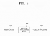
- an artificial intelligence model 400 is a model trained to segment the tubular structure 420 from the medical image when receiving the medical image 410 as an input.
- the artificial intelligence model 400 may be implemented with various types of artificial neural networks such as a convolutional neural network (CNN).
- CNN convolutional neural network
- the artificial intelligence model 400 may be generated by training with a supervised learning method based on training data including medical images labeling the aorta. Since the training process of the artificial intelligence model 400 itself is already a widely known method, an additional explanation thereof will be omitted.
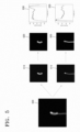
- FIG. 5 is a diagram illustrating an example of detecting the diameter of a tubular structure from a two-dimensional (2D) medical image using a diameter detection method according to an embodiment.
- the diameter detection apparatus 100 acquires an image 500 obtained by segmenting a tubular structure from a 2D medical image. Since the 2D medical image is displayed on one plane by overlapping a plurality of tissues, the tubular structure may be overlapped and displayed on an image 500 obtained by segmenting a region of the tubular structure from the medical image. For example, the aorta may appear to overlap some sections as shown in the image 500 of FIG. 5 according to the photographing direction.
- the diameter detection apparatus 100 segments each tubular structure from the image 500 when the tubular structures overlap.
- the diameter detection apparatus 100 may segment overlapping tubular structures using the brightness value within the image 500.
- Various existing image analysis algorithms or artificial intelligence models for dividing overlapped images may be applied to the present embodiment.
- the diameter detection apparatus 100 performs diameter detection from the images 520 and 525 on the tubular structures 510 and 515. For example, the diameter detection apparatus 100 determines the center line on each tubular structure, as seen in FIGS. 2 and 3 , and detects the diameters of the tubular structure at various locations based on the center line. The diameter detection apparatus 100 may display a diameter for each position of each tubular structure as shown in graphs 530 and 535.
- FIG. 6 is a diagram illustrating an example of detecting the diameter of a tubular structure from a three-dimensional (3D) medical image using a diameter detection method according to an embodiment.
- the diameter detection apparatus 100 may generate images 600 and 650 each including a tubular structure region based on a brightness (i.e., a Hounsfield unit (HU) value) of a voxel from a 3D medical image.
- a brightness i.e., a Hounsfield unit (HU) value
- This embodiment presents an example 610 of detecting the aorta diameter in a normal case and an example 660 of detecting the aorta diameter in the presence of an aneurysm.
- the diameter detection apparatus 100 may output diameters for respective positions to the graphs 620 and 670.
- the diameter detection apparatus 100 may determine the risk of aneurysm based on the diameter data of the aorta in a normal case. For example, when the maximum diameter of the aorta is swollen more than a certain amount compared to the normal case, such aorta diameters may be determined as an aneurysm.
- the diameter detection apparatus 100 may digitize and present the risk of aneurysm based on the difference between the maximum diameter of the normal aorta and the maximum diameter of the swollen aorta.
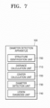
- FIG. 7 is a diagram illustrating a configuration of an example of a diameter detection apparatus according to an embodiment.
- the diameter detection apparatus 100 includes a structure identification unit 700, a distance calculation unit 710, a center calculation unit 720, a diameter detection unit 730, and a lesion diagnosis unit 740.
- the lesion diagnosis unit 740 may be omitted.
- the diameter detection apparatus 100 may be implemented as a computing device including a memory, a processor, and an input/output device. In this case, each component may be implemented in software (program) and then performed by a processor after being loaded on a memory.
- the structure identification unit 700 identifies a tubular structure from a 2D or 3D medical image. For example, the structure identification unit 700 may segment a tubular structure such as the aorta based on a brightness value of the medical image, or segment a tubular structure using the artificial intelligence model of FIG. 4 . In another embodiment, the structure identification unit 700 may generate an image including a tubular structure as a binary image.
- the distance calculation unit 710 obtains a distance map indicating a distance from each point inside the tubular structure to a boundary of the tubular structure.
- the distance calculation unit 710 may obtain a distance map indicating the distance to each point in the tubular structure using Euclidean distance transform.
- the center calculation unit 720 obtains central points based on a gradient of a distance value in the distance map and connects the central points to create a center line.
- a kind of ridge may be obtained by connecting points having a small change in distance value at each point in the tubular structure.
- various methods for obtaining central points based on a distance map may be applied to the present embodiment and embodiments are not limited to specific examples.
- the center calculation unit 720 may obtain a center line smoothly connected in a single line by applying interpolation or smoothing.
- the diameter detection unit 730 determines the distance to the boundary of the tubular structure in a direction perpendicular to the center line and obtains the diameter of the tubular structure for each position.
- the diameter detection unit 730 may obtain the diameter of the tubular structure at regular intervals along the center line, or may obtain the diameter of the tubular structure at each and every point located on the center line.
- the lesion diagnosis unit 740 determines a lesion based on the diameter of the tubular structure. For example, the lesion diagnosis unit 740 may compare the diameter of the aorta identified from the medical image with the diameter of the aorta of a normal group stored in advance to determine the occurrence of aneurysm or a degree of risk (a predefined degree of risk according to a difference in diameter size between the normal group and a control group). In another embodiment, the lesion diagnosis unit 740 may determine whether an aneurysm occurs or a degree of risk based on a change in the diameters of the aorta in medical images captured at various times for the same patient.
- the lesion diagnosis unit 740 may determine that there is a risk of an aneurysm if the maximum diameter of the aorta changes to a predetermined size or more in a plurality of medical images taken at multiple points in time.
- the lesion diagnosis unit 740 may digitize and output the risk of aneurysm based on a change in the diameter size of the aorta over time.
- the present method according to the disclosure may also be implemented as computer-readable program code on a computer-readable recording medium.
- the computer-readable recording medium includes all types of recording devices in which data readable by a computer system is stored. Examples of computer-readable recording media include ROM, RAM, CD-ROM, magnetic tape, floppy disk, optical data storage device, and the like.
- computer-readable recording media are distributed in a network-connected computer system so that computer-readable code may be stored and executed in a distributed manner.
- the diameter of a tubular structure such as an artery may be automatically determined from a 2D or 3D medical image.
- the risk of aneurysm may be numerically provided by detecting the diameter of the aorta.
Landscapes
- Engineering & Computer Science (AREA)
- Health & Medical Sciences (AREA)
- Physics & Mathematics (AREA)
- Life Sciences & Earth Sciences (AREA)
- Medical Informatics (AREA)
- Computer Vision & Pattern Recognition (AREA)
- General Physics & Mathematics (AREA)
- Theoretical Computer Science (AREA)
- General Health & Medical Sciences (AREA)
- Nuclear Medicine, Radiotherapy & Molecular Imaging (AREA)
- Radiology & Medical Imaging (AREA)
- Pathology (AREA)
- Public Health (AREA)
- Veterinary Medicine (AREA)
- Animal Behavior & Ethology (AREA)
- Biophysics (AREA)
- Surgery (AREA)
- Biomedical Technology (AREA)
- Heart & Thoracic Surgery (AREA)
- Molecular Biology (AREA)
- High Energy & Nuclear Physics (AREA)
- Quality & Reliability (AREA)
- Vascular Medicine (AREA)
- Physiology (AREA)
- Optics & Photonics (AREA)
- Geometry (AREA)
- Multimedia (AREA)
- Cardiology (AREA)
- Dentistry (AREA)
- Oral & Maxillofacial Surgery (AREA)
- Apparatus For Radiation Diagnosis (AREA)
- Magnetic Resonance Imaging Apparatus (AREA)
Abstract
Provided are a method and an apparatus for detecting the diameter of a tubular structure in a medical image. The apparatus for detecting the diameter of a tubular structure is configured to identify the tubular structure in a two-dimensional or three-dimensional medical image, calculate a distance map indicating a distance from each point inside the tubular structure to a boundary of the tubular structure, calculate central points, based on a gradient of a distance value in the distance map, connect the central points to create a center line, and obtain the diameter of the tubular structure for each location by determining a distance between the center line and the boundary of the tubular structure in a direction perpendicular to the center line.
Description
- This application is based on the support project of the Ministry of Health and Welfare (Task number: 1465034178, Task number: HI21C1074050021, Research project name: Construction of big data specialized in intensive care and developing AI-based CDSS).
- This application is based on and claims priority under 35 U.S.C. §119 to
Korean Patent Application No. 10-2023-0117642, filed on September 05, 2023 - The disclosure relates to a method and apparatus for detecting the diameters of tubular structures in medical images, and more particularly, to a method and apparatus for detecting the diameters of tubular structures such as aorta for diagnosis of lesions.
- The shapes of tubular structures such as arteries may be identified from medical images. For example, lesions may be diagnosed by identifying the shapes of arteries and the like from a completed tomography (CT) or magnetic resistance imaging (MRI) image. Although an aorta aneurysm occurs slowly without major symptoms, continuous monitoring and early detection are important for diseases such as aorta aneurysms as the mortality rate is more than 80 % after an acute rupture occurs. Although medical staff may directly measure the diameters of blood vessels in medical images, it is difficult to accurately measure the diameter change of a gradually progressing aorta aneurysm without error every time, and it takes much time because the diameters should be obtained from various locations of blood vessels.
- The disclosure provides a method and an apparatus for automatically detecting a diameter of a tubular structure in a medical image.
- Additional aspects will be set forth in part in the description which follows and, in part, will be apparent from the description, or may be learned by practice of the presented embodiments of the disclosure.
- According to an aspect of the disclosure, a method of detecting a diameter of a tubular structure includes identifying the tubular structure in a two-dimensional or three-dimensional medical image, obtaining a distance map indicating a distance from each point inside the tubular structure to a boundary of the tubular structure, obtaining central points based on a gradient of a distance value in the distance map, creating a center line by connecting the central points, and obtaining the diameter of the tubular structure for each location by determining a distance between the center line and the boundary of the tubular structure in a direction perpendicular to the center line.
- According to another aspect of the disclosure, an apparatus for detecting a diameter of a tubular structure includes a structural identification unit configured to identify the tubular structure in a two-dimensional or three-dimensional medical image, a distance calculation unit configured to calculate a distance map indicating a distance from each point inside the tubular structure to a boundary of the tubular structure, a center calculation unit configured to calculate central points based on a gradient of a distance value in the distance map and connect the central points to create a center line, and a diameter detection unit configured to determine a distance to the boundary of the tubular structure in a direction perpendicular to the center line and detect the diameter of the tubular structure for each location.
- The above and other aspects, features, and advantages of certain embodiments of the disclosure will be more apparent from the following description taken in conjunction with the accompanying drawings, in which:
-
FIG. 1 is a diagram illustrating an example of a diameter detection apparatus for detecting the diameter of a tubular structure, according to an embodiment; -
FIGS. 2 and3 are flowcharts illustrating an example of a method of detecting the diameter of a tubular structure, according to an embodiment; -
FIG. 4 is a diagram illustrating an example of a method of segmenting a tubular structure from a medical image by using an artificial intelligence model, according to an embodiment; -
FIG. 5 is a diagram illustrating an example of detecting the diameter of a tubular structure from a two-dimensional (2D) medical image by using a diameter detection method, according to an embodiment; -
FIG. 6 is a diagram illustrating an example of detecting the diameter of a tubular structure from a three-dimensional (3D) medical image by using a diameter detection method, according to an embodiment; and -
FIG. 7 is a diagram illustrating a configuration of an example of a diameter detection apparatus according to an embodiment. - Reference will now be made in detail to embodiments, examples of which are illustrated in the accompanying drawings, wherein like reference numerals refer to like elements throughout. In this regard, the present embodiments may have different forms and should not be construed as being limited to the descriptions set forth herein. Accordingly, the embodiments are merely described below, by referring to the figures, to explain aspects of the present description. As used herein, the term "and/or" includes any and all combinations of one or more of the associated listed items. Expressions such as "at least one of," when preceding a list of elements, modify the entire list of elements and do not modify the individual elements of the list.
- Hereinafter, a method and an apparatus for detecting the diameter of a tubular structure according to an embodiment of the present invention will be described below in detail with reference to the accompanying drawings.
-
FIG. 1 is a diagram illustrating an example of a diameter detection apparatus of detecting diameter of a tubular structure according to an embodiment. - Referring to
FIG. 1 , when receiving amedical image 110 as an input, adiameter detection apparatus 100 identifies a tubular structure region in the medical image and then detects thediameters 120 of the tubular structure at various locations. Here, themedical image 110 may be a 2D medical image such as an X-ray image or a 3D medical image such as CT or MRI. - The tubular structure in the
medical image 110 is a narrow and long tubular structure, and may be various types of human tissues such as arteries (e.g., aorta), veins, and airways. However, hereinafter, for convenience of explanation, an example of detecting the diameter of the aorta will be mainly described below. -
FIGS. 2 and3 are flowcharts illustrating an example of a method of detecting the diameter of a tubular structure according to an embodiment. - Referring to
FIGS. 2 and3 , thediameter detection apparatus 100 identifies at least one tubular structure (e.g., the aortic image 300) in a medical image 110 (S200). For example, thediameter detection apparatus 100 may segment an aortic region from a 2D or 3D medical image capturing the chest. Various types of algorithms for segmenting a specific human tissue in themedical image 110 may be applied to the present embodiment. Alternatively, thediameter detection apparatus 100 may use an artificial intelligence model to segment at least one tubular structure in themedical image 110, which will be described again inFIG. 4 . - In another embodiment, the
diameter detection apparatus 100 may convert themedical image 110 into a binary image including a region of the tubular structure. For example, thediameter detection apparatus 100 may generate a binary image in which the values of the coordinates in the tubular structure region are converted to "0" (or white), and the values of the coordinates in the background region outside the tubular structure region are converted to "1" (or black).FIG. 3 illustrates an example of obtaining a diameter based onbinary images 
- Here, (x,y) denotes coordinates in the medical image.
Equation 1 is an example of a 2D medical image, and in the case of a 3D medical image, the coordinates may include (x, y, z). - The
diameter detection apparatus 100 generates adistance map 310 indicating a distance from each point inside the tubular structure to a boundary of the tubular structure (S210). Thediameter detection apparatus 100 may obtain a distance map using Euclidean distance transform. For example, thediameter detection apparatus 100 may identify, as a distance value at any one point, the shortest distance from the point in the tubular structure (i.e., pixel coordinates of a 2D medical image and voxel coordinates of a 3D medical image) to points that form the boundary of the tubular structure. For example, the distance map may be a map showing a distance value of each point (coordinate or voxel) in the tubular structure. thedistance maps 
- Here, (x,y) means a coordinate value of a specific point in the tubular structure, and (x',y') means a coordinate value of a boundary point of the tubular structure.
- The
diameter detection apparatus 100 obtains central points (i.e., ridge points 320) based on the gradient of the distance value in thedistance map 310, and connects the central points to generate a center line 330 (i.e., skeleton) (S220). In an embodiment, thediameter detection apparatus 100 may determine, as thecentral points 320, points in thedistance map 310 where the magnitude of the gradient of the distance value is less than or equal to a preset threshold. This is expressed in a mathematical equation as follows.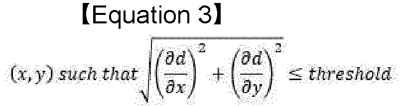
- Here, d denotes a distance value obtained in
Equation 2, and the threshold may be predefined as various values according to embodiments. A coordinate value of (x, y) satisfying Equation 3 becomes thecentral points 320. - In another embodiment, the
central points 320 may be spaced apart by a predetermined distance or noise may exist therein. In this case, the diameter detection apparatus may add central points using interpolation between thecentral points 320 spaced apart from each other by a predetermined distance, or connect and smooth the central points. For example, thediameter detection apparatus 100 may connect a plurality ofcentral points 320 using a linear one-dimensional (1D)-interpolation method and smooth the plurality ofcentral points 320 using a 1D-Gaussian filter. In addition, various conventional methods of connecting and smoothing a plurality ofcentral points 320 to make one line segment may be applied to the present embodiment. - The
diameter detection apparatus 100 detects the diameter (e.g., the maximum diameter 340) of the tubular structure by using the distance between thecenter line 330 and the boundary of the tubular structure in a direction perpendicular to the center line 330 (S230). For example, thediameter detection apparatus 100 may obtain a tangent line at each point of the center line, and obtain the distance between the center line and the boundary of the tubular structure using a line segment perpendicular to the tangent line (i.e., a line segment perpendicular to the center line) based on thebinary images diameter detection apparatus 100 may detect the diameter of the tubular structure at various points of the center line (e.g., central points at regular intervals) or at all points constituting the center line (i.e., all central points). In addition, thediameter detection apparatus 100 may detect and output a maximum value among diameters for respective locations of the tubular structure (as shown in agraph 350 ofFIG. 3 ). - In another embodiment, the
diameter detection apparatus 100 may determine a lesion based on the diameter of the tubular structure. For example, thediameter detection apparatus 100 may determine the risk of aneurysm by detecting the diameter of the aorta from a chest medical image. This will be described again with reference toFIG. 6 . -
FIG. 4 is a diagram illustrating an example of a method of segmenting a tubular structure from a medical image using an artificial intelligence model according to an embodiment. - Referring to
FIG. 4 , anartificial intelligence model 400 is a model trained to segment thetubular structure 420 from the medical image when receiving themedical image 410 as an input. Theartificial intelligence model 400 may be implemented with various types of artificial neural networks such as a convolutional neural network (CNN). - In an embodiment, the
artificial intelligence model 400 may be generated by training with a supervised learning method based on training data including medical images labeling the aorta. Since the training process of theartificial intelligence model 400 itself is already a widely known method, an additional explanation thereof will be omitted. -
FIG. 5 is a diagram illustrating an example of detecting the diameter of a tubular structure from a two-dimensional (2D) medical image using a diameter detection method according to an embodiment. - Referring to
FIG. 5 , thediameter detection apparatus 100 acquires animage 500 obtained by segmenting a tubular structure from a 2D medical image. Since the 2D medical image is displayed on one plane by overlapping a plurality of tissues, the tubular structure may be overlapped and displayed on animage 500 obtained by segmenting a region of the tubular structure from the medical image. For example, the aorta may appear to overlap some sections as shown in theimage 500 ofFIG. 5 according to the photographing direction. - The
diameter detection apparatus 100 segments each tubular structure from theimage 500 when the tubular structures overlap. In an embodiment, thediameter detection apparatus 100 may segment overlapping tubular structures using the brightness value within theimage 500. Various existing image analysis algorithms or artificial intelligence models for dividing overlapped images may be applied to the present embodiment. - The
diameter detection apparatus 100 performs diameter detection from theimages tubular structures diameter detection apparatus 100 determines the center line on each tubular structure, as seen inFIGS. 2 and3 , and detects the diameters of the tubular structure at various locations based on the center line. Thediameter detection apparatus 100 may display a diameter for each position of each tubular structure as shown ingraphs -
FIG. 6 is a diagram illustrating an example of detecting the diameter of a tubular structure from a three-dimensional (3D) medical image using a diameter detection method according to an embodiment. - Referring to
FIG. 6 , thediameter detection apparatus 100 may generateimages diameter detection apparatus 100 may output diameters for respective positions to thegraphs - The
diameter detection apparatus 100 may determine the risk of aneurysm based on the diameter data of the aorta in a normal case. For example, when the maximum diameter of the aorta is swollen more than a certain amount compared to the normal case, such aorta diameters may be determined as an aneurysm. Thediameter detection apparatus 100 may digitize and present the risk of aneurysm based on the difference between the maximum diameter of the normal aorta and the maximum diameter of the swollen aorta. -
FIG. 7 is a diagram illustrating a configuration of an example of a diameter detection apparatus according to an embodiment. - Referring to
FIG. 7 , thediameter detection apparatus 100 includes astructure identification unit 700, adistance calculation unit 710, acenter calculation unit 720, adiameter detection unit 730, and alesion diagnosis unit 740. In an embodiment, thelesion diagnosis unit 740 may be omitted. In another embodiment, thediameter detection apparatus 100 may be implemented as a computing device including a memory, a processor, and an input/output device. In this case, each component may be implemented in software (program) and then performed by a processor after being loaded on a memory. - The
structure identification unit 700 identifies a tubular structure from a 2D or 3D medical image. For example, thestructure identification unit 700 may segment a tubular structure such as the aorta based on a brightness value of the medical image, or segment a tubular structure using the artificial intelligence model ofFIG. 4 . In another embodiment, thestructure identification unit 700 may generate an image including a tubular structure as a binary image. - The
distance calculation unit 710 obtains a distance map indicating a distance from each point inside the tubular structure to a boundary of the tubular structure. For example, thedistance calculation unit 710 may obtain a distance map indicating the distance to each point in the tubular structure using Euclidean distance transform. - The
center calculation unit 720 obtains central points based on a gradient of a distance value in the distance map and connects the central points to create a center line. A kind of ridge may be obtained by connecting points having a small change in distance value at each point in the tubular structure. In addition, various methods for obtaining central points based on a distance map may be applied to the present embodiment and embodiments are not limited to specific examples. In another embodiment, when the central points are not continuous or have an even line shape, thecenter calculation unit 720 may obtain a center line smoothly connected in a single line by applying interpolation or smoothing. - The
diameter detection unit 730 determines the distance to the boundary of the tubular structure in a direction perpendicular to the center line and obtains the diameter of the tubular structure for each position. Thediameter detection unit 730 may obtain the diameter of the tubular structure at regular intervals along the center line, or may obtain the diameter of the tubular structure at each and every point located on the center line. - The
lesion diagnosis unit 740 determines a lesion based on the diameter of the tubular structure. For example, thelesion diagnosis unit 740 may compare the diameter of the aorta identified from the medical image with the diameter of the aorta of a normal group stored in advance to determine the occurrence of aneurysm or a degree of risk (a predefined degree of risk according to a difference in diameter size between the normal group and a control group). In another embodiment, thelesion diagnosis unit 740 may determine whether an aneurysm occurs or a degree of risk based on a change in the diameters of the aorta in medical images captured at various times for the same patient. That is, thelesion diagnosis unit 740 may determine that there is a risk of an aneurysm if the maximum diameter of the aorta changes to a predetermined size or more in a plurality of medical images taken at multiple points in time. Thelesion diagnosis unit 740 may digitize and output the risk of aneurysm based on a change in the diameter size of the aorta over time. - The present method according to the disclosure may also be implemented as computer-readable program code on a computer-readable recording medium. The computer-readable recording medium includes all types of recording devices in which data readable by a computer system is stored. Examples of computer-readable recording media include ROM, RAM, CD-ROM, magnetic tape, floppy disk, optical data storage device, and the like. In addition, computer-readable recording media are distributed in a network-connected computer system so that computer-readable code may be stored and executed in a distributed manner.
- According to an embodiment of the disclosure, the diameter of a tubular structure such as an artery may be automatically determined from a 2D or 3D medical image. In another embodiment, the risk of aneurysm may be numerically provided by detecting the diameter of the aorta.
- It should be understood that embodiments described herein should be considered in a descriptive sense only and not for purposes of limitation. Descriptions of features or aspects within each embodiment should typically be considered as available for other similar features or aspects in other embodiments. While one or more embodiments have been described with reference to the figures, it will be understood by those of ordinary skill in the art that various changes in form and details may be made therein without departing from the spirit and scope of the disclosure as defined by the following claims.
- The invention could be inter alia defined by the following examples:
- 1. A method of detecting a diameter of a tubular structure, the method comprising: preferably receiving a two-dimensional (2D) medical image or a three-dimensional (3D), identifying the tubular structure in the two-dimensional (2D) or three-dimensional (3D) medical image;
- obtaining a distance map indicating a distance from each point inside the tubular structure to a boundary of the tubular structure;
- obtaining central points, based on a gradient of a distance value in the distance map;
- creating a center line by connecting the central points; and
- obtaining the diameter of the tubular structure for each location by determining a distance between the center line and the boundary of the tubular structure in a direction perpendicular to the center line.
- 2. The method of example 1, wherein the 2D or 3D medical image is an X-ray image or a CT or MRI image.
- 3. The method of any one of the preceding examples, wherein the tubular structure comprises an aorta.
- 4. The method of example 3, further comprising determining a risk of aneurysm, based on a diameter of the aorta.
- 5. The method of any one of the preceding examples, wherein the identifying of the tubular structure comprises generating a binary image including a region corresponding to the tubular structure in the 2D or 3D medical image.
- 6. The method of any one of the preceding examples, wherein the obtaining of the distance map comprises generating a distance map including a shortest distance from each point in the tubular structure to a boundary of the tubular structure.
- 7. The method of any one of the preceding examples, wherein the creating of the center line comprises:
- if there are central points spaced apart from each other by a certain distance, adding central points using interpolation; and
- connecting and smoothing the central points.
- 8. An apparatus for detecting a diameter of a tubular structure, the apparatus comprising:
a structural identification unit configured to identify the tubular structure in a two-dimensional or three-dimensional medical image;- a distance calculation unit configured to calculate a distance map indicating a distance from each point inside the tubular structure to a boundary of the tubular structure;
- a center calculation unit configured to calculate central points, based on a gradient of a distance value in the distance map, and connect the central points to create a center line; and
- a diameter detection unit configured to determine a distance to the boundary of the tubular structure in a direction perpendicular to the center line and detect the diameter of the tubular structure for each location.
- 9. The apparatus of example 8, further comprising a lesion diagnosis unit configured to, when the tubular structure is an aorta, determine a risk of aneurysm, based on the diameter of the aorta.
- 10. A computer-readable recording medium on which a computer program for performing the method of any one of the examples 1 to 7 is recorded.
Claims (10)
- A method of detecting a diameter of a tubular structure, the method comprising:identifying the tubular structure in a two-dimensional (2D) or three-dimensional (3D) medical image;obtaining a distance map indicating a distance from each point inside the tubular structure to a boundary of the tubular structure;obtaining central points, based on a gradient of a distance value in the distance map;creating a center line by connecting the central points; andobtaining the diameter of the tubular structure for each location by determining a distance between the center line and the boundary of the tubular structure in a direction perpendicular to the center line.
- The method of claim 1, wherein the 2D or 3D medical image is an X-ray image or a CT or MRI image.
- The method of claim 1, wherein the tubular structure comprises an aorta.
- The method of claim 3, further comprising determining a risk of aneurysm, based on a diameter of the aorta.
- The method of claim 1, wherein the identifying of the tubular structure comprises generating a binary image including a region corresponding to the tubular structure in the 2D or 3D medical image.
- The method of claim 1, wherein the obtaining of the distance map comprises generating a distance map including a shortest distance from each point in the tubular structure to a boundary of the tubular structure.
- The method of claim 1, wherein the creating of the center line comprises:if there are central points spaced apart from each other by a certain distance, adding central points using interpolation; andconnecting and smoothing the central points.
- An apparatus for detecting a diameter of a tubular structure, the apparatus comprising:a structural identification unit configured to identify the tubular structure in a two-dimensional or three-dimensional medical image;a distance calculation unit configured to calculate a distance map indicating a distance from each point inside the tubular structure to a boundary of the tubular structure;a center calculation unit configured to calculate central points, based on a gradient of a distance value in the distance map, and connect the central points to create a center line; anda diameter detection unit configured to determine a distance to the boundary of the tubular structure in a direction perpendicular to the center line and detect the diameter of the tubular structure for each location.
- The apparatus of claim 8, further comprising a lesion diagnosis unit configured to, when the tubular structure is an aorta, determine a risk of aneurysm, based on the diameter of the aorta.
- A computer-readable recording medium on which a computer program for performing the method of claim 1 is recorded.
Applications Claiming Priority (1)
| Application Number | Priority Date | Filing Date | Title |
|---|---|---|---|
| KR1020230117642A KR20250035239A (en) | 2023-09-05 | 2023-09-05 | Method and apparatus for detecting diameter of tubular structure in medical image |
Publications (1)
| Publication Number | Publication Date |
|---|---|
| EP4521356A1 true EP4521356A1 (en) | 2025-03-12 |
Family
ID=91739133
Family Applications (1)
| Application Number | Title | Priority Date | Filing Date |
|---|---|---|---|
| EP24185099.9A Withdrawn EP4521356A1 (en) | 2023-09-05 | 2024-06-27 | Method and apparatus for detecting diameter of tubular structure in medical image |
Country Status (3)
| Country | Link |
|---|---|
| US (1) | US20250078262A1 (en) |
| EP (1) | EP4521356A1 (en) |
| KR (1) | KR20250035239A (en) |
Citations (3)
| Publication number | Priority date | Publication date | Assignee | Title |
|---|---|---|---|---|
| US20080033302A1 (en) * | 2006-04-21 | 2008-02-07 | Siemens Corporate Research, Inc. | System and method for semi-automatic aortic aneurysm analysis |
| CN115937239A (en) * | 2022-12-27 | 2023-04-07 | 沈阳东软智能医疗科技研究院有限公司 | Aortic vessel segmentation method, device, storage medium and electronic equipment |
| KR20230117642A (en) | 2017-07-28 | 2023-08-08 | 프로페셔날 디에테틱스 인터내셔날 에스.알.엘. | Compositions comprising amino acids for use in the treatment of mitochondrial dysfunction-related disease |
-
2023
- 2023-09-05 KR KR1020230117642A patent/KR20250035239A/en active Pending
-
2024
- 2024-06-17 US US18/745,218 patent/US20250078262A1/en active Pending
- 2024-06-27 EP EP24185099.9A patent/EP4521356A1/en not_active Withdrawn
Patent Citations (3)
| Publication number | Priority date | Publication date | Assignee | Title |
|---|---|---|---|---|
| US20080033302A1 (en) * | 2006-04-21 | 2008-02-07 | Siemens Corporate Research, Inc. | System and method for semi-automatic aortic aneurysm analysis |
| KR20230117642A (en) | 2017-07-28 | 2023-08-08 | 프로페셔날 디에테틱스 인터내셔날 에스.알.엘. | Compositions comprising amino acids for use in the treatment of mitochondrial dysfunction-related disease |
| CN115937239A (en) * | 2022-12-27 | 2023-04-07 | 沈阳东软智能医疗科技研究院有限公司 | Aortic vessel segmentation method, device, storage medium and electronic equipment |
Non-Patent Citations (3)
| Title |
|---|
| ANONYMOUS: "MSD Manuals Global Medical Knowledge", 2 December 2024 (2024-12-02), XP093229759, Retrieved from the Internet <URL:https://www.msdmanuals.com/> [retrieved on 20241202] * |
| BOUIX S ET AL: "Flux driven automatic centerline extraction", MEDICAL IMAGE ANALYSIS, OXFORD UNIVERSITY PRESS, OXOFRD, GB, vol. 9, no. 3, 1 June 2005 (2005-06-01), pages 209 - 221, XP027847051, ISSN: 1361-8415, [retrieved on 20050601] * |
| BREWSTER DC ET AL: "Abdominal Aortic Aneurysm Size and Rupture Risk*", 1 January 2003 (2003-01-01), MSD Manual Professional Version, XP093229768, Retrieved from the Internet <URL:https://www.msdmanuals.com/professional/multimedia/table/abdominal-aortic-aneurysm-size-and-rupture-risk> [retrieved on 20241202] * |
Also Published As
| Publication number | Publication date |
|---|---|
| US20250078262A1 (en) | 2025-03-06 |
| KR20250035239A (en) | 2025-03-12 |
Similar Documents
| Publication | Publication Date | Title |
|---|---|---|
| JP7488541B2 (en) | Method and system for identification of cerebrovascular abnormalities - Patents.com | |
| US12458232B2 (en) | Medical image visualization apparatus and method for diagnosis of aorta | |
| EP3886702B1 (en) | Most relevant x-ray image selection for hemodynamic simulation | |
| JP5584006B2 (en) | Projection image generation apparatus, projection image generation program, and projection image generation method | |
| US8422752B2 (en) | Diagnosis assisting apparatus, diagnosis assisting method, and storage medium in which a diagnosis assisting program is recorded | |
| US11122981B2 (en) | Arterial wall characterization in optical coherence tomography imaging | |
| EP3871184B1 (en) | Orientation detection for 2d vessel segmentation for angio-ffr | |
| CN110866914A (en) | Method, system, device and medium for evaluating cerebral aneurysm hemodynamic index | |
| US12079989B2 (en) | Identifying boundaries of lesions within image data | |
| JP2007289704A (en) | System and method for semi-automated analysis of aortic aneurysms | |
| CN114943682B (en) | Method and device for detecting anatomical key points in three-dimensional angiography images | |
| CN111210401A (en) | Automatic detection and quantification of aorta from medical images | |
| JP2020515333A (en) | Imaging with contrast agent injection | |
| KR102402011B1 (en) | Medical image process apparatus and medical image learning method, and medical image process method | |
| JP7803869B2 (en) | Program, information processing device and information processing method | |
| CN116309346A (en) | Medical image detection method, device, equipment, storage medium and program product | |
| JP5558793B2 (en) | Image processing method, image processing apparatus, and program | |
| US12569329B2 (en) | Medical image processing apparatus, medical image processing method, and non-transitory computer-readable storage medium | |
| US20250078262A1 (en) | Method and apparatus for detecting diameter of tubular structure in medical image | |
| WO2020054019A1 (en) | Image processing device, image processing method, and program | |
| US20250266163A1 (en) | Vulnerable plaque assessment and outcome prediction in coronary artery disease | |
| WO2026020541A1 (en) | Sparse representation method and apparatus for vascular model, device, medium, and program product | |
| EP4281929B1 (en) | Vessel shape | |
| KR102781491B1 (en) | blood vessel diameter detection method and apparatus therefor | |
| KR20230085817A (en) | Aortic dissection visualization apparatus and method |
Legal Events
| Date | Code | Title | Description |
|---|---|---|---|
| PUAI | Public reference made under article 153(3) epc to a published international application that has entered the european phase |
Free format text: ORIGINAL CODE: 0009012 |
|
| STAA | Information on the status of an ep patent application or granted ep patent |
Free format text: STATUS: REQUEST FOR EXAMINATION WAS MADE |
|
| 17P | Request for examination filed |
Effective date: 20240627 |
|
| AK | Designated contracting states |
Kind code of ref document: A1 Designated state(s): AL AT BE BG CH CY CZ DE DK EE ES FI FR GB GR HR HU IE IS IT LI LT LU LV MC ME MK MT NL NO PL PT RO RS SE SI SK SM TR |
|
| STAA | Information on the status of an ep patent application or granted ep patent |
Free format text: STATUS: THE APPLICATION IS DEEMED TO BE WITHDRAWN |
|
| 18D | Application deemed to be withdrawn |
Effective date: 20250913 |