EP4521253A2 - Implementing safety measures in applications - Google Patents
Implementing safety measures in applications Download PDFInfo
- Publication number
- EP4521253A2 EP4521253A2 EP24220572.2A EP24220572A EP4521253A2 EP 4521253 A2 EP4521253 A2 EP 4521253A2 EP 24220572 A EP24220572 A EP 24220572A EP 4521253 A2 EP4521253 A2 EP 4521253A2
- Authority
- EP
- European Patent Office
- Prior art keywords
- data
- controller
- application controller
- memory device
- vehicle
- Prior art date
- Legal status (The legal status is an assumption and is not a legal conclusion. Google has not performed a legal analysis and makes no representation as to the accuracy of the status listed.)
- Pending
Links
Images

Classifications
-
- B—PERFORMING OPERATIONS; TRANSPORTING
- B60—VEHICLES IN GENERAL
- B60W—CONJOINT CONTROL OF VEHICLE SUB-UNITS OF DIFFERENT TYPE OR DIFFERENT FUNCTION; CONTROL SYSTEMS SPECIALLY ADAPTED FOR HYBRID VEHICLES; ROAD VEHICLE DRIVE CONTROL SYSTEMS FOR PURPOSES NOT RELATED TO THE CONTROL OF A PARTICULAR SUB-UNIT
- B60W30/00—Purposes of road vehicle drive control systems not related to the control of a particular sub-unit, e.g. of systems using conjoint control of vehicle sub-units
- B60W30/08—Active safety systems predicting or avoiding probable or impending collision or attempting to minimise its consequences
- B60W30/09—Taking automatic action to avoid collision, e.g. braking and steering
-
- B—PERFORMING OPERATIONS; TRANSPORTING
- B60—VEHICLES IN GENERAL
- B60W—CONJOINT CONTROL OF VEHICLE SUB-UNITS OF DIFFERENT TYPE OR DIFFERENT FUNCTION; CONTROL SYSTEMS SPECIALLY ADAPTED FOR HYBRID VEHICLES; ROAD VEHICLE DRIVE CONTROL SYSTEMS FOR PURPOSES NOT RELATED TO THE CONTROL OF A PARTICULAR SUB-UNIT
- B60W50/00—Details of control systems for road vehicle drive control not related to the control of a particular sub-unit, e.g. process diagnostic or vehicle driver interfaces
- B60W50/0098—Details of control systems ensuring comfort, safety or stability not otherwise provided for
-
- G—PHYSICS
- G05—CONTROLLING; REGULATING
- G05B—CONTROL OR REGULATING SYSTEMS IN GENERAL; FUNCTIONAL ELEMENTS OF SUCH SYSTEMS; MONITORING OR TESTING ARRANGEMENTS FOR SUCH SYSTEMS OR ELEMENTS
- G05B9/00—Safety arrangements
- G05B9/02—Safety arrangements electric
- G05B9/03—Safety arrangements electric with multiple-channel loop, i.e. redundant control systems
-
- G—PHYSICS
- G06—COMPUTING OR CALCULATING; COUNTING
- G06F—ELECTRIC DIGITAL DATA PROCESSING
- G06F3/00—Input arrangements for transferring data to be processed into a form capable of being handled by the computer; Output arrangements for transferring data from processing unit to output unit, e.g. interface arrangements
- G06F3/06—Digital input from, or digital output to, record carriers, e.g. RAID, emulated record carriers or networked record carriers
- G06F3/0601—Interfaces specially adapted for storage systems
- G06F3/0602—Interfaces specially adapted for storage systems specifically adapted to achieve a particular effect
- G06F3/0614—Improving the reliability of storage systems
- G06F3/0619—Improving the reliability of storage systems in relation to data integrity, e.g. data losses, bit errors
-
- G—PHYSICS
- G06—COMPUTING OR CALCULATING; COUNTING
- G06F—ELECTRIC DIGITAL DATA PROCESSING
- G06F3/00—Input arrangements for transferring data to be processed into a form capable of being handled by the computer; Output arrangements for transferring data from processing unit to output unit, e.g. interface arrangements
- G06F3/06—Digital input from, or digital output to, record carriers, e.g. RAID, emulated record carriers or networked record carriers
- G06F3/0601—Interfaces specially adapted for storage systems
- G06F3/0628—Interfaces specially adapted for storage systems making use of a particular technique
- G06F3/0646—Horizontal data movement in storage systems, i.e. moving data in between storage devices or systems
- G06F3/065—Replication mechanisms
-
- G—PHYSICS
- G06—COMPUTING OR CALCULATING; COUNTING
- G06F—ELECTRIC DIGITAL DATA PROCESSING
- G06F3/00—Input arrangements for transferring data to be processed into a form capable of being handled by the computer; Output arrangements for transferring data from processing unit to output unit, e.g. interface arrangements
- G06F3/06—Digital input from, or digital output to, record carriers, e.g. RAID, emulated record carriers or networked record carriers
- G06F3/0601—Interfaces specially adapted for storage systems
- G06F3/0628—Interfaces specially adapted for storage systems making use of a particular technique
- G06F3/0655—Vertical data movement, i.e. input-output transfer; data movement between one or more hosts and one or more storage devices
- G06F3/0658—Controller construction arrangements
-
- G—PHYSICS
- G06—COMPUTING OR CALCULATING; COUNTING
- G06F—ELECTRIC DIGITAL DATA PROCESSING
- G06F3/00—Input arrangements for transferring data to be processed into a form capable of being handled by the computer; Output arrangements for transferring data from processing unit to output unit, e.g. interface arrangements
- G06F3/06—Digital input from, or digital output to, record carriers, e.g. RAID, emulated record carriers or networked record carriers
- G06F3/0601—Interfaces specially adapted for storage systems
- G06F3/0628—Interfaces specially adapted for storage systems making use of a particular technique
- G06F3/0655—Vertical data movement, i.e. input-output transfer; data movement between one or more hosts and one or more storage devices
- G06F3/0659—Command handling arrangements, e.g. command buffers, queues, command scheduling
-
- G—PHYSICS
- G06—COMPUTING OR CALCULATING; COUNTING
- G06F—ELECTRIC DIGITAL DATA PROCESSING
- G06F3/00—Input arrangements for transferring data to be processed into a form capable of being handled by the computer; Output arrangements for transferring data from processing unit to output unit, e.g. interface arrangements
- G06F3/06—Digital input from, or digital output to, record carriers, e.g. RAID, emulated record carriers or networked record carriers
- G06F3/0601—Interfaces specially adapted for storage systems
- G06F3/0668—Interfaces specially adapted for storage systems adopting a particular infrastructure
- G06F3/0671—In-line storage system
- G06F3/0673—Single storage device
- G06F3/0679—Non-volatile semiconductor memory device, e.g. flash memory, one time programmable memory [OTP]
-
- G—PHYSICS
- G11—INFORMATION STORAGE
- G11C—STATIC STORES
- G11C7/00—Arrangements for writing information into, or reading information out from, a digital store
- G11C7/24—Memory cell safety or protection circuits, e.g. arrangements for preventing inadvertent reading or writing; Status cells; Test cells
-
- B—PERFORMING OPERATIONS; TRANSPORTING
- B60—VEHICLES IN GENERAL
- B60W—CONJOINT CONTROL OF VEHICLE SUB-UNITS OF DIFFERENT TYPE OR DIFFERENT FUNCTION; CONTROL SYSTEMS SPECIALLY ADAPTED FOR HYBRID VEHICLES; ROAD VEHICLE DRIVE CONTROL SYSTEMS FOR PURPOSES NOT RELATED TO THE CONTROL OF A PARTICULAR SUB-UNIT
- B60W50/00—Details of control systems for road vehicle drive control not related to the control of a particular sub-unit, e.g. process diagnostic or vehicle driver interfaces
- B60W2050/0001—Details of the control system
- B60W2050/0002—Automatic control, details of type of controller or control system architecture
- B60W2050/0004—In digital systems, e.g. discrete-time systems involving sampling
- B60W2050/0005—Processor details or data handling, e.g. memory registers or chip architecture
Definitions
- the present disclosure relates generally to semiconductor memory and methods, and more particularly, to apparatuses and methods related to a safety controller.
- the driver In conventional motor vehicles (e.g., automobiles, cars, trucks, buses, etc.), the driver is critical to operating the vehicle's control system. For example, the driver of a conventional motor vehicle makes decisions regarding the safe operation of the vehicle. Such decisions may include decisions related to the speed of the vehicle, steering of the vehicle, obstacle and/or hazard recognition, and obstacle and/or hazard avoidance. However, a driver's ability to make these decisions and operate the vehicle's control system may be limited in some situations. For example, driver impairment, fatigue, attentiveness, and/or other factors such as visibility (e.g., due to weather or changes in terrain) may limit a driver's ability to safely operate a conventional motor vehicle and/or its control system.
- visibility e.g., due to weather or changes in terrain
- autonomous vehicles In order to alleviate the deficiencies resulting from driver operation of a conventional motor vehicle, various manufacturers have experimented with autonomous vehicles. While autonomous vehicles may allow for a reduction in issues that may arise as a result of the driver's ability to operate the conventional motor vehicle becoming lessened, autonomous vehicles have their own shortcomings.
- autonomous vehicles may rely on various sensors and/or cameras to determine a speed at which to operate the vehicle, steering of the vehicle, obstacle and/or hazard recognition, and obstacle and/or hazard avoidance.
- Data from these sensors and/or devices may be corrupted while being stored on memory or transmitted on a memory bus, for example.
- Data may be corrupted by errors induced by noise, cross talk, and/or other sources of errors.
- a host may receive commands to safely operate the autonomous vehicle and provide updates to the autonomous vehicle based on data.
- the autonomous vehicle may cease to operate or, in worse case scenarios, fail to provide adequate obstacle and/or hazard recognition, and obstacle and/or hazard avoidance, which may result in injury or death to passengers in the autonomous vehicle.
- An example apparatus comprises a memory resource configured to store data and transmit data.
- the apparatus may further include a safety controller coupled to the memory resource configured to receive the data from the memory resource, receive latched data from an application controller, and determine whether to allow an output of a command and/or commands from the application controller in response to a comparison of the data from the memory resource and the latched data from the application controller.
- autonomous vehicles may include a memory device to provide data to a controller.
- the data can include vehicle sensor data, for example obstacle and/or hazard information.
- the memory can store critical code including firmware, software, and/or temporary calculations derived from the data.
- multiple entities e.g., a memory device and/or controller
- Embodiments can be implemented to provide safety measures in applications (e.g., autonomous driving applications in vehicles).
- triple redundancy can include two entities transmitting the same code.
- a third entity can receive the codes and identify whether one or more of the codes are corrupted.
- redundancy can allow a system to avoid failure and/or an accident in the field. For example, redundancy can ensure the correctness of a data transmission between a memory device and a controller. Redundancy can also ensure the correctness of the execution by the controller of the proper code.
- autonomous vehicles may be susceptible to data corruption.
- Data can be corrupted by noise, cross talk, and/or other sources of error. Redundancy prevents a command, for example, "activate brakes" from being sent when the command is based on corrupt data.
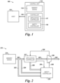
- FIG. 1 is a block diagram of a system 100 in the form of a host 110 and a control unit 112 in accordance with a number of embodiments of the present disclosure.
- a memory device 114, a controller 116, an application controller 117, and/or a safety controller 118 might also be separately considered an "apparatus.”
- apparatus 100 includes a host 110 and a control unit 112.
- the control unit 112 can include a memory resource (e.g., memory device 114) and a controller 116.
- the controller 1 16 can include an application controller 117 and a safety controller 118.
- the memory device 114 may include volatile and/or non-volatile memory configured to store instructions executable by the controller 116.
- the memory device 114 may include flash memory, for example NOR, read-only memory (ROM), programmable read-only memory (PROM), erasable programmable read-only memory (EPROM), electrically erasable programmable read-only memory (EEPROM), dynamic random-access memory (DRAM), static random-access memory (SRAM), and/or other suitable storage media.
- the memory device 114 can be a double edge device.
- the apparatus 100 may be used in autonomous driving applications.
- the control unit 112 can be located on a vehicle.
- the memory device 114 of the control unit 112 may store autonomous vehicle data.
- autonomous vehicle data For example, critical code (e.g., firmware, specific parameters, and data) for an autonomous driving application.
- the data can include data collected from vehicle sensors, photographic data collected from vehicle cameras, and/or a combination thereof.
- the memory device 114 can store data and transmit data.
- the data can be transmitted to the controller 116 including the application controller 117 and the safety controller 118.
- the application controller 117 can receive data from the memory device 114.
- the received data can be used by the application controller 117 to generate commands.
- the data can include information regarding a vehicle approaching a stop sign.
- the application controller 117 can generate a command to stop the car.
- the application can then send the generated command and/or commands to be executed by the vehicle.
- data can be transmitted to the safety controller 118.
- the safety controller 118 can receive data from the memory device 114 and the application controller 117.
- the safety controller 118 can prevent a command and/or commands from being executed by the vehicle in response to comparing the data from the memory device 114 and the data from the application controller 117.
- Figure 2 is a flow diagram 213 associated with triple redundancy in an autonomous driving application in accordance with a number of embodiments of the present disclosure.
- the memory device 214, application controller 217, and the safety controller 218 may be configured to exchange data and/or communications.
- the memory device 214 may transmit data to the safety controller 218 via data paths 222 and 224.
- the memory device 214 may transmit data to the application controller 217 via data path 220.
- the application controller 217 may transmit data to the safety controller 218 via data path 226.
- the application controller 217 can communicate with safety controller 218 via communication path 230.
- the safety controller 218 can communicate with the application controller 217 and the multiplexer 236 (e.g., MUX) via communication path 228.
- MUX multiplexer
- the memory device 214 may store and transmit data.
- the safety controller 218 can be coupled to the memory device 214 via the data paths 222 and 224.
- the safety controller 218 can be configured to receive the data from the memory device 214.
- the data from the memory device 214 can be received by the safety controller 218 as a reverse output via data path 222 and as a direct output via data path 224.
- the reverse output of the data can be transmitted by the memory device 214 on a falling edge of a clock and the direct output of the data can be transmitted by the memory device 214 on a rising edge of the clock, as further discussed in Figure 3 .
- the memory device 214 may transmit data to the application controller 217.
- the application controller 217 can be coupled to the memory device 214 via the data path 220.
- the application controller 217 can be configured to receive the data from the memory device 214.
- the data from the memory device 214 can be received as a direct output by the application controller 217 via data path 220.
- the direct output of the data can be transmitted by the memory device 214 on a rising edge of a clock, as further discussed in Figure 3 .
- the application controller 217 may latch the data in response to receiving the data from the memory device 214.
- the application controller 217 can transmit the latched data to the safety controller 218.
- the application controller 217 can latch the data on a rising edge of the clock.
- the safety controller 218 can be configured to receive latched data from the application controller 217.
- the latched data from the application controller 217 can be received by the safety controller 218 as an output via data path 226.
- the output of the latched data can be transmitted by the application controller 217 on a falling edge of a clock, as further discussed in Figure 3 .
- the safety controller 218 can generate a response and/or determine whether to allow an output of commands via data path 232 from the application controller 217 in response to a comparison of the data from the memory device 214 and the latched data from the application controller 217.
- the data received by the application controller 217 from the memory device 214 can be used to generate commands.
- the commands can be associated with the data from the memory device 214 and can be output from the application controller 217 in response to the application controller 217 receiving the data from the memory device 214.
- the data can include information regarding a higher speed limit.
- the application controller 217 can generate a command and/or commands to accelerate the speed of the vehicle to reach the higher speed limit.
- the data received by the application controller 217 and used to generate the command to accelerate the vehicle could be corrupted, which could mean the vehicle when executing the command is accelerating even though the speed limit did not change and/or the speed limit is different than what is indicated to the application controller 217 by the corrupted data.
- the safety controller 218 can prevent a command from being executed via data path 234 by the vehicle.
- the safety controller 218 can prevent a command from being executed by generating a response and/or transmitting a flag to the MUX 236 and the application controller 217 via communication path 228.
- the safety controller 218 can transmit a flag in response to identifying a difference between the data from the memory device 214 and the latched data from the application controller 217.
- the safety controller 218 can compare the reverse output and direct output from the memory device 214 and the output from the application controller 217. If one and/or more of the data outputs are different, the safety controller 218 can transmit a flag.
- the data outputs being different can indicate that at least one of the data outputs have been corrupted while stored and/or transmitted.
- the memory device 214 and/or the application controller 217 can transmit another portion of data in response to the application controller 217 receiving the flag via communication path 228 from the safety controller 218.
- the flag can indicate that the data outputs from the memory device 214 and/or the application controller 217 are corrupt and that the data needs to be resent.
- the application controller 217 can output a safety acknowledgment signal via communication path 230 to the safety controller 218.
- the safety acknowledgment signal can be sent in response to receiving the flag from the safety controller 218.
- the acknowledgment signal can notify the safety controller 218 that the application controller 217 received the flag and/or the application controller 217 and/or the memory device 214 are resending the data.
- the safety controller 218 can remove the flag. In the absence of a flag and/or if a response is not generated, the MUX 236 will allow the application controller 217 commands to be executed by the vehicle via data path 234.
- the safety controller 218 can allow commands from the application controller 217 to be executed in response to identifying a match between the data from the memory resource 214 and the latched data from the application controller 217. For example, commands can be executed if the direct output data from the memory device 214 and the output data from the application controller 21 7 match and are the opposite of the reverse output data from the memory device 214. Also, the reverse output data can be put in a direct output data state once received by the safety controller 218, and compared against the other output data. Commands can be executed if the direct output data from the memory device 214 and the output data from the application controller 217 match and are the opposite of the reverse output data from the memory device 214.
- FIG. 3 is a diagram of a memory output of a double edge device in accordance with a number of embodiments of the present disclosure.
- a double edge device is a memory device (e.g., memory device 214 in Fig. 2 ).
- data can be transmitted on rising edges 352 and 356 and falling edges 354 and 358 of a double edge device.
- Data 0 at 342 can be transmitted on rising edge 352.
- Data 0 can be a direct output from memory because it is transmitted on a rising edge 352.
- Data 0' at 344 can be a reverse output because it is transmitted on a falling edge 354.
- Data 1 at 346 can be transmitted as a direct output on rising edge 356 and Data 1' at 348 can be transmitted as a reverse output of Data 1 on the falling edge 358.
- the direct output from the memory device can be represented by Data 0 at 342 being transmitted on the rising edge 352.
- the reverse output from the memory device can be represented by Data 0' at 344 being transmitted on the falling edge 354.
- the application controller e.g., application controller 217 in Fig. 2
- latching data from the memory device can be represented by Data 1 at 346 being latched on the rising edge 356.
- the reverse output from the application controller can be represented by Data 1' at 348 being transmitted on the falling edge 358.
- the direct output from memory device (e.g., memory device 214 in Fig. 2 ) transmitted on the rising edge 352, the reverse output from the memory device transmitted on the falling edge 354, and the output from the application controller (e.g., application controller 217 in Fig. 2 ) transmitted on the falling edge 358 can be received by a safety controller (e.g., safety controller 218 in Fig. 2 ).
- the safety controller may allow commands to be outputted from the application controller in response to identifying a match between the data from the memory device and the latched data from the application controller.
- the memory device (e.g., memory device 214 in Fig. 2 ) can be programmed as a double edge device such that the direct data is programmed on every other row of the memory device and the reverse data is programmed adjacent to the corresponding direct data.
- the direct data can be programmed on even addresses and the reverse data can be programmed on odd addresses so that the direct data is transmitted on the rising edge 352 and the reverse data is transmitted on the falling edge 354.
- Figure 4 is a flow diagram including reverse circuitry outputting data in accordance with a number of embodiments of the present disclosure.
- the reverse circuitry as shown in Figure 4 can be used to reverse the pattern of the data from the memory device 414.
- the data can be autonomous vehicle data.
- the data can include photographic data collected from vehicle cameras, and/or data collected from vehicle sensors, but the data is not limited to photographic data or vehicle sensor data.
- the memory device 414 can store and transmit data.
- the memory device 414 can be coupled to reverse circuitry 462.
- the memory device 414 can transmit data 460 to the reverse circuitry.
- the data transmitted by the memory device 414 can be transmitted on a rising edge of a clock and can be a direct output.
- the reverse circuitry 462 can receive the data as a direct output from the memory device 414.
- the reverse circuitry 462 can copy the direct output and reverse the direct output pattern to create a reverse output.
- the reverse circuitry 462 can transmit the direct output 464 from the memory device 414 and the reverse output 465 to a multiplexer 469 (e.g., MUX).
- a multiplexer 469 e.g., MUX
- the combined signal 468 can be received by the application controller 417.
- the application controller 417 can latch the data of the combined signal 468.
- the data can be latched on a rising edge (e.g., rising edge 356 in Fig. 3 ).
- the latched data can be transmitted to the safety controller.
- the latched data can be transmitted as an output sent on a falling edge (e.g., falling edge 358 in Fig. 3 ) of a signal.
- the combined signal 468 can also be received by the safety controller 418.
- the safety controller 418 can determine whether to allow an output of commands from the application controller 417 in response to a comparison of the data from the memory device 414 and the latched data from the application controller 417. For example, the safety controller 418 can compare the direct output and the reverse output from the memory device 414 and the reverse output from the application controller 417
- the application controller may latch the data in response to receiving the data from the memory resource.
- the data may be received by the application controller as a direct output and the data may be received by the safety controller as a reverse output.
- a direct output may be transmitted by the memory resource on a rising edge of a clock and a reverse output is transmitted by the memory resource on a falling edge of the clock.
- a direct output may be programmed on every other row of the memory resource and a reverse output may be programmed adjacent to the corresponding direct output.
- Latched data may be transmitted on a falling edge of a clock.
- an apparatus comprising:
- the memory resource may transmit another portion of data in response to the application controller receiving the flag from the safety controller.
- the application controller may output a safety acknowledgment signal to the safety controller in response to receiving the flag from the safety controller.
- the safety controller may remove the flag in response to receiving a safety acknowledgment signal from the application controller.
- an apparatus comprising:
- the data may include data collected from vehicle sensors, photographic data collected from vehicle cameras, or combinations thereof.
- Also disclosed herein is a method, comprising:
- the method may include transmitting the data from the memory resource as a direct output to a safety controller.
- the method may include transmitting the data from the memory resource to the application controller as a direct output.
- the data from the memory resource to a safety controller may be transmitted on a rising edge of a clock.
- the data from the memory resource to the application controller may be transmitted on a rising edge of a clock.
- Also disclosed herein is a method, comprising:
- Commands may be output from the application controller in response to the response not being generated.
Landscapes
- Engineering & Computer Science (AREA)
- Theoretical Computer Science (AREA)
- Human Computer Interaction (AREA)
- Physics & Mathematics (AREA)
- General Physics & Mathematics (AREA)
- Automation & Control Theory (AREA)
- General Engineering & Computer Science (AREA)
- Mechanical Engineering (AREA)
- Transportation (AREA)
- Computer Security & Cryptography (AREA)
- Techniques For Improving Reliability Of Storages (AREA)
- Storage Device Security (AREA)
- Small-Scale Networks (AREA)
- Debugging And Monitoring (AREA)
- Selective Calling Equipment (AREA)
- Hardware Redundancy (AREA)
Abstract
Description
- The present disclosure relates generally to semiconductor memory and methods, and more particularly, to apparatuses and methods related to a safety controller.
- In conventional motor vehicles (e.g., automobiles, cars, trucks, buses, etc.), the driver is critical to operating the vehicle's control system. For example, the driver of a conventional motor vehicle makes decisions regarding the safe operation of the vehicle. Such decisions may include decisions related to the speed of the vehicle, steering of the vehicle, obstacle and/or hazard recognition, and obstacle and/or hazard avoidance. However, a driver's ability to make these decisions and operate the vehicle's control system may be limited in some situations. For example, driver impairment, fatigue, attentiveness, and/or other factors such as visibility (e.g., due to weather or changes in terrain) may limit a driver's ability to safely operate a conventional motor vehicle and/or its control system.
- In order to alleviate the deficiencies resulting from driver operation of a conventional motor vehicle, various manufacturers have experimented with autonomous vehicles. While autonomous vehicles may allow for a reduction in issues that may arise as a result of the driver's ability to operate the conventional motor vehicle becoming lessened, autonomous vehicles have their own shortcomings.
- For example, autonomous vehicles may rely on various sensors and/or cameras to determine a speed at which to operate the vehicle, steering of the vehicle, obstacle and/or hazard recognition, and obstacle and/or hazard avoidance. Data from these sensors and/or devices may be corrupted while being stored on memory or transmitted on a memory bus, for example. Data may be corrupted by errors induced by noise, cross talk, and/or other sources of errors. A host may receive commands to safely operate the autonomous vehicle and provide updates to the autonomous vehicle based on data. If the data the commands are based on is corrupted the autonomous vehicle may cease to operate or, in worse case scenarios, fail to provide adequate obstacle and/or hazard recognition, and obstacle and/or hazard avoidance, which may result in injury or death to passengers in the autonomous vehicle.
-
-
Figure 1 is a block diagram of a system in the form of a host and a memory device in accordance with a number of embodiments of the present disclosure. -
Figure 2 is a flow diagram associated with triple redundancy in an autonomous driving application in accordance with a number of embodiments of the present disclosure. -
Figure 3 is a diagram of a memory output of a double edge device in accordance with a number of embodiments of the present disclosure. -
Figure 4 is a flow diagram including reverse circuitry outputting data in accordance with a number of embodiments of the present disclosure. - The present disclosure includes apparatuses and methods related to a safety controller. An example apparatus comprises a memory resource configured to store data and transmit data. The apparatus may further include a safety controller coupled to the memory resource configured to receive the data from the memory resource, receive latched data from an application controller, and determine whether to allow an output of a command and/or commands from the application controller in response to a comparison of the data from the memory resource and the latched data from the application controller.
- In some approaches, autonomous vehicles may include a memory device to provide data to a controller. The data can include vehicle sensor data, for example obstacle and/or hazard information. The memory can store critical code including firmware, software, and/or temporary calculations derived from the data.
- To reduce the probability of the autonomous vehicle executing the wrong code, multiple entities (e.g., a memory device and/or controller) can execute and identify a correct output, which can be referred to as redundancy. Embodiments can be implemented to provide safety measures in applications (e.g., autonomous driving applications in vehicles). As an example, triple redundancy can include two entities transmitting the same code. A third entity can receive the codes and identify whether one or more of the codes are corrupted.
- In some embodiments, redundancy can allow a system to avoid failure and/or an accident in the field. For example, redundancy can ensure the correctness of a data transmission between a memory device and a controller. Redundancy can also ensure the correctness of the execution by the controller of the proper code.
- For example, because operation of the control system in an autonomous vehicle may be wholly or partly handled by control circuitry, autonomous vehicles may be susceptible to data corruption. Data can be corrupted by noise, cross talk, and/or other sources of error. Redundancy prevents a command, for example, "activate brakes" from being sent when the command is based on corrupt data.
- The figures herein follow a numbering convention in which the first digit or digits correspond to the drawing figure number and the remaining digits identify an element or component in the drawing. Similar elements or components between different figures may be identified by the use of similar digits. For example, 114 may reference element "14" in
Figure 1 , and a similar element may be referenced as 214 inFigure 2 . As will be appreciated, elements shown in the various embodiments herein can be added, exchanged, and/or eliminated so as to provide a number of additional embodiments of the present disclosure. In addition, as will be appreciated, the proportion and the relative scale of the elements provided in the figures are intended to illustrate certain embodiments of the present invention, and should not be taken in a limiting sense. -
Figure 1 is a block diagram of asystem 100 in the form of ahost 110 and acontrol unit 112 in accordance with a number of embodiments of the present disclosure. As used herein, amemory device 114, acontroller 116, anapplication controller 117, and/or asafety controller 118 might also be separately considered an "apparatus." - As shown in
Figure 1 ,apparatus 100 includes ahost 110 and acontrol unit 112. Thecontrol unit 112 can include a memory resource (e.g., memory device 114) and acontroller 116. Thecontroller 1 16 can include anapplication controller 117 and asafety controller 118. - The
memory device 114 may include volatile and/or non-volatile memory configured to store instructions executable by thecontroller 116. For example, thememory device 114 may include flash memory, for example NOR, read-only memory (ROM), programmable read-only memory (PROM), erasable programmable read-only memory (EPROM), electrically erasable programmable read-only memory (EEPROM), dynamic random-access memory (DRAM), static random-access memory (SRAM), and/or other suitable storage media. In some embodiments, thememory device 114 can be a double edge device. - The
apparatus 100 may be used in autonomous driving applications. For example, thecontrol unit 112 can be located on a vehicle. Thememory device 114 of thecontrol unit 112 may store autonomous vehicle data. For example, critical code (e.g., firmware, specific parameters, and data) for an autonomous driving application. The data can include data collected from vehicle sensors, photographic data collected from vehicle cameras, and/or a combination thereof. In some embodiments thememory device 114 can store data and transmit data. The data can be transmitted to thecontroller 116 including theapplication controller 117 and thesafety controller 118. - The
application controller 117 can receive data from thememory device 114. The received data can be used by theapplication controller 117 to generate commands. For example, the data can include information regarding a vehicle approaching a stop sign. Theapplication controller 117 can generate a command to stop the car. The application can then send the generated command and/or commands to be executed by the vehicle. - In some embodiments, data can be transmitted to the
safety controller 118. Thesafety controller 118 can receive data from thememory device 114 and theapplication controller 117. Thesafety controller 118 can prevent a command and/or commands from being executed by the vehicle in response to comparing the data from thememory device 114 and the data from theapplication controller 117. -
Figure 2 is a flow diagram 213 associated with triple redundancy in an autonomous driving application in accordance with a number of embodiments of the present disclosure. As shown inFigure 2 , thememory device 214,application controller 217, and thesafety controller 218 may be configured to exchange data and/or communications. Thememory device 214 may transmit data to thesafety controller 218 viadata paths memory device 214 may transmit data to theapplication controller 217 viadata path 220. Theapplication controller 217 may transmit data to thesafety controller 218 viadata path 226. Theapplication controller 217 can communicate withsafety controller 218 viacommunication path 230. Thesafety controller 218 can communicate with theapplication controller 217 and the multiplexer 236 (e.g., MUX) viacommunication path 228. - In some embodiments, the
memory device 214 may store and transmit data. Thesafety controller 218 can be coupled to thememory device 214 via thedata paths safety controller 218 can be configured to receive the data from thememory device 214. The data from thememory device 214 can be received by thesafety controller 218 as a reverse output viadata path 222 and as a direct output viadata path 224. The reverse output of the data can be transmitted by thememory device 214 on a falling edge of a clock and the direct output of the data can be transmitted by thememory device 214 on a rising edge of the clock, as further discussed inFigure 3 . - The
memory device 214 may transmit data to theapplication controller 217. Theapplication controller 217 can be coupled to thememory device 214 via thedata path 220. Theapplication controller 217 can be configured to receive the data from thememory device 214. The data from thememory device 214 can be received as a direct output by theapplication controller 217 viadata path 220. The direct output of the data can be transmitted by thememory device 214 on a rising edge of a clock, as further discussed inFigure 3 . - In some embodiments, the
application controller 217 may latch the data in response to receiving the data from thememory device 214. Theapplication controller 217 can transmit the latched data to thesafety controller 218. Theapplication controller 217 can latch the data on a rising edge of the clock. Thesafety controller 218 can be configured to receive latched data from theapplication controller 217. The latched data from theapplication controller 217 can be received by thesafety controller 218 as an output viadata path 226. The output of the latched data can be transmitted by theapplication controller 217 on a falling edge of a clock, as further discussed inFigure 3 . - The
safety controller 218 can generate a response and/or determine whether to allow an output of commands viadata path 232 from theapplication controller 217 in response to a comparison of the data from thememory device 214 and the latched data from theapplication controller 217. The data received by theapplication controller 217 from thememory device 214 can be used to generate commands. The commands can be associated with the data from thememory device 214 and can be output from theapplication controller 217 in response to theapplication controller 217 receiving the data from thememory device 214. For example, the data can include information regarding a higher speed limit. Theapplication controller 217 can generate a command and/or commands to accelerate the speed of the vehicle to reach the higher speed limit. However, the data received by theapplication controller 217 and used to generate the command to accelerate the vehicle could be corrupted, which could mean the vehicle when executing the command is accelerating even though the speed limit did not change and/or the speed limit is different than what is indicated to theapplication controller 217 by the corrupted data. - In some embodiments, the
safety controller 218 can prevent a command from being executed viadata path 234 by the vehicle. Thesafety controller 218 can prevent a command from being executed by generating a response and/or transmitting a flag to theMUX 236 and theapplication controller 217 viacommunication path 228. Thesafety controller 218 can transmit a flag in response to identifying a difference between the data from thememory device 214 and the latched data from theapplication controller 217. In some embodiments, thesafety controller 218 can compare the reverse output and direct output from thememory device 214 and the output from theapplication controller 217. If one and/or more of the data outputs are different, thesafety controller 218 can transmit a flag. The data outputs being different (e.g., different than the direct output from thememory device 214 and the latched data from theapplication controller 217 matching and being the opposite of the reverse output from the memory device 214) can indicate that at least one of the data outputs have been corrupted while stored and/or transmitted. - The
memory device 214 and/or theapplication controller 217 can transmit another portion of data in response to theapplication controller 217 receiving the flag viacommunication path 228 from thesafety controller 218. The flag can indicate that the data outputs from thememory device 214 and/or theapplication controller 217 are corrupt and that the data needs to be resent. - In some embodiments, the
application controller 217 can output a safety acknowledgment signal viacommunication path 230 to thesafety controller 218. The safety acknowledgment signal can be sent in response to receiving the flag from thesafety controller 218. The acknowledgment signal can notify thesafety controller 218 that theapplication controller 217 received the flag and/or theapplication controller 217 and/or thememory device 214 are resending the data. - In response to receiving the safety acknowledgment signal from the
application controller 217, thesafety controller 218 can remove the flag. In the absence of a flag and/or if a response is not generated, theMUX 236 will allow theapplication controller 217 commands to be executed by the vehicle viadata path 234. - The
safety controller 218 can allow commands from theapplication controller 217 to be executed in response to identifying a match between the data from thememory resource 214 and the latched data from theapplication controller 217. For example, commands can be executed if the direct output data from thememory device 214 and the output data from the application controller 21 7 match and are the opposite of the reverse output data from thememory device 214. Also, the reverse output data can be put in a direct output data state once received by thesafety controller 218, and compared against the other output data. Commands can be executed if the direct output data from thememory device 214 and the output data from theapplication controller 217 match and are the opposite of the reverse output data from thememory device 214. -
Figure 3 is a diagram of a memory output of a double edge device in accordance with a number of embodiments of the present disclosure. A double edge device is a memory device (e.g.,memory device 214 inFig. 2 ). As shown inFigure 3 , data can be transmitted on risingedges edges edge 352. Data 0 can be a direct output from memory because it is transmitted on a risingedge 352. Data 0' at 344 can be a reverse output because it is transmitted on a fallingedge 354. Reverse output meaning that Data 0' is identical but reverse (e.g., opposite) of Data 0.Data 1 at 346 can be transmitted as a direct output on risingedge 356 and Data 1' at 348 can be transmitted as a reverse output ofData 1 on the fallingedge 358. - The direct output from the memory device (e.g.,
memory device 214 inFig. 2 ) can be represented by Data 0 at 342 being transmitted on the risingedge 352. The reverse output from the memory device can be represented by Data 0' at 344 being transmitted on the fallingedge 354. The application controller (e.g.,application controller 217 inFig. 2 ) latching data from the memory device can be represented byData 1 at 346 being latched on the risingedge 356. The reverse output from the application controller can be represented by Data 1' at 348 being transmitted on the fallingedge 358. - The direct output from memory device (e.g.,
memory device 214 inFig. 2 ) transmitted on the risingedge 352, the reverse output from the memory device transmitted on the fallingedge 354, and the output from the application controller (e.g.,application controller 217 inFig. 2 ) transmitted on the fallingedge 358 can be received by a safety controller (e.g.,safety controller 218 inFig. 2 ). The safety controller may allow commands to be outputted from the application controller in response to identifying a match between the data from the memory device and the latched data from the application controller. - The memory device (e.g.,
memory device 214 inFig. 2 ) can be programmed as a double edge device such that the direct data is programmed on every other row of the memory device and the reverse data is programmed adjacent to the corresponding direct data. For example, the direct data can be programmed on even addresses and the reverse data can be programmed on odd addresses so that the direct data is transmitted on the risingedge 352 and the reverse data is transmitted on the fallingedge 354. -
Figure 4 is a flow diagram including reverse circuitry outputting data in accordance with a number of embodiments of the present disclosure. The reverse circuitry as shown inFigure 4 can be used to reverse the pattern of the data from thememory device 414. The data can be autonomous vehicle data. For example, the data can include photographic data collected from vehicle cameras, and/or data collected from vehicle sensors, but the data is not limited to photographic data or vehicle sensor data. - The
memory device 414 can store and transmit data. Thememory device 414 can be coupled to reversecircuitry 462. Thememory device 414 can transmit data 460 to the reverse circuitry. The data transmitted by thememory device 414 can be transmitted on a rising edge of a clock and can be a direct output. - The
reverse circuitry 462 can receive the data as a direct output from thememory device 414. Thereverse circuitry 462 can copy the direct output and reverse the direct output pattern to create a reverse output. Thereverse circuitry 462 can transmit thedirect output 464 from thememory device 414 and thereverse output 465 to a multiplexer 469 (e.g., MUX). - The
MUX 469 can combine signals. TheMUX 469 can combine thedirect output 464 and thereverse output 465 into one signal. TheMUX 469 can include aclock 466. Theclock 466 can be used to initiate the sending of the second signal to ensure both signals are sent in one signal. For example, thedirect output 464 can be transmitted on a rising edge (e.g., risingedge 352 inFig. 3 ) to theapplication controller 417 and thesafety controller 418 until the clock initiates the sending of the reverse output on a falling edge (e.g., fallingedge 354 inFig. 3 ) to theapplication controller 417 and thesafety controller 418. - The combined
signal 468 can be received by theapplication controller 417. Theapplication controller 417 can latch the data of the combinedsignal 468. The data can be latched on a rising edge (e.g., risingedge 356 inFig. 3 ). The latched data can be transmitted to the safety controller. The latched data can be transmitted as an output sent on a falling edge (e.g., fallingedge 358 inFig. 3 ) of a signal. - The combined
signal 468 can also be received by thesafety controller 418. Thesafety controller 418 can determine whether to allow an output of commands from theapplication controller 417 in response to a comparison of the data from thememory device 414 and the latched data from theapplication controller 417. For example, thesafety controller 418 can compare the direct output and the reverse output from thememory device 414 and the reverse output from theapplication controller 417 - Also disclosed herein is an apparatus, comprising:
- a memory resource configured to:
- store data; and
- transmit the data, and
- a safety controller coupled to the memory resource, wherein the safety controller is configured to implement safety measures in applications by:
- receiving the data from the memory resource;
- receiving latched data from an application controller; and
- determining whether to allow an output of commands from the application controller in response to a comparison of the data from the memory resource and the latched data from the application controller.
- The memory resource may be a NOR device.
- The application controller may latch the data in response to receiving the data from the memory resource.
- The data may be received by the application controller as a direct output and the data may be received by the safety controller as a reverse output.
- A direct output may be transmitted by the memory resource on a rising edge of a clock and a reverse output is transmitted by the memory resource on a falling edge of the clock.
- A direct output may be programmed on every other row of the memory resource and a reverse output may be programmed adjacent to the corresponding direct output.
- Latched data may be transmitted on a falling edge of a clock.
- Also disclosed herein is an apparatus, comprising:
- a memory resource configured to:
- store data, and
- transmit the data; and
- a safety controller coupled to the memory resource, wherein the safety controller is configured to:
- receive the data from the memory resource,
- receive latched data from an application controller; and
- transmit a flag to the application controller in response to the safety controller identifying a difference between the data from the memory resource and the latched data from the application controller.
- The memory resource may transmit another portion of data in response to the application controller receiving the flag from the safety controller.
- The application controller may output a safety acknowledgment signal to the safety controller in response to receiving the flag from the safety controller.
- The safety controller may remove the flag in response to receiving a safety acknowledgment signal from the application controller.
- Also disclosed herein is an apparatus, comprising:
- a memory resource configured to:
- store data; and
- transmit the data; and
- a safety controller coupled to the memory resource, wherein the safety controller is configured to:
- receive the data from the memory resource;
- receive latched data from an application controller; and
- allow commands to be output from the application controller in response to identifying a match between the data from the memory resource and the latched data from the application controller.
- The data may include data collected from vehicle sensors, photographic data collected from vehicle cameras, or combinations thereof.
- Also disclosed herein is a method, comprising:
- receiving data from a memory resource;
- receiving latched data from an application controller; and
- determining whether to output commands from the application controller in response to a comparison of the data from the memory resource and the latched data from the application controller.
- The method may include transmitting the data from the memory resource as a direct output to a safety controller.
- The method may include transmitting the data from the memory resource to the application controller as a direct output.
- The data from the memory resource to a safety controller may be transmitted on a rising edge of a clock.
- The data from the memory resource to the application controller may be transmitted on a rising edge of a clock.
- Also disclosed herein is a method, comprising:
- receiving data from a memory resource;
- receiving latched data from an application controller; and
- generating a response to an output from the application controller in response to a comparison of the data from the memory resource and the latched data from the application controller.
- Commands may be output from the application controller in response to the response not being generated.
- Although specific embodiments have been illustrated and described herein, those of ordinary skill in the art will appreciate that an arrangement calculated to achieve the same results can be substituted for the specific embodiments shown. This disclosure is intended to cover adaptations or variations of one or more embodiments of the present disclosure. It is to be understood that the above description has been made in an illustrative fashion, and not a restrictive one. Combination of the above embodiments, and other embodiments not specifically described herein will be apparent to those of skill in the art upon reviewing the above description. The scope of the one or more embodiments of the present disclosure includes other applications in which the above structures and methods are used. Therefore, the scope of one or more embodiments of the present disclosure should be determined with reference to the appended claims, along with the full range of equivalents to which such claims are entitled.
- In the foregoing Detailed Description, some features are grouped together in a single embodiment for the purpose of streamlining the disclosure. This method of disclosure is not to be interpreted as reflecting an intention that the disclosed embodiments of the present disclosure have to use more features than are expressly recited in each claim. Rather, as the following claims reflect, inventive subject matter lies in less than all features of a single disclosed embodiment. Thus, the following claims are hereby incorporated into the Detailed Description, with each claim standing on its own as a separate embodiment.
Claims (15)
- An apparatus, comprising:
an application controller (117, 217, 417) configured to:generate a command based on data collected from a sensor of a vehicle; andtransmit the command to be executed by the vehicle; and a safety controller (118, 218, 418) configured to:receive the command;determine, based on the data, whether to prevent the command from being executed by the vehicle; andprevent the command from being executed by the vehicle. - The apparatus of claim 1, wherein the command is to activate brakes.
- The apparatus of claim 1, wherein the data includes information regarding the vehicle approaching a stop sign.
- The apparatus of claim 3, wherein the command is to stop the vehicle.
- The apparatus of claim 1, wherein the data includes information regarding a speed limit.
- The apparatus of claim 5, wherein the command is to accelerate a speed of the vehicle.
- The apparatus of claim 1, further comprising a memory device (114, 214, 414) configured to store the data.
- The apparatus of claim 7, wherein the memory device is configured to transmit the data to the application controller.
- The apparatus of claim 7, wherein the memory device is configured to transmit the data to the safety controller.
- The apparatus of claim 1, wherein the sensor is a camera.
- The apparatus of claim 10, wherein the data is photographic data.
- The apparatus of claim 1, wherein the data is obstacle or hazard information.
- A method, comprising:generating a command at an application controller (117, 217, 417) based on data collected from a sensor of a vehicle;transmitting the command at the application controller to be executed by the vehicle;receiving the command at a safety controller (118, 218, 418);determining, based on the data, whether to prevent the command from being executed by the vehicle at the safety controller; andpreventing the command from being executed by the vehicle.
- The method of claim 13, further comprising receiving the data at the application controller from a memory device (114, 214, 414).
- The method of claim 13, further comprising using redundancy to prevent the command from being executed by the vehicle.
Applications Claiming Priority (3)
| Application Number | Priority Date | Filing Date | Title |
|---|---|---|---|
| US15/847,201 US10836400B2 (en) | 2017-12-19 | 2017-12-19 | Implementing safety measures in applications |
| PCT/US2018/065108 WO2019125847A1 (en) | 2017-12-19 | 2018-12-12 | Implementing safety measures in applications |
| EP18891221.6A EP3729431B1 (en) | 2017-12-19 | 2018-12-12 | Implementing safety measures in applications |
Related Parent Applications (2)
| Application Number | Title | Priority Date | Filing Date |
|---|---|---|---|
| EP18891221.6A Division EP3729431B1 (en) | 2017-12-19 | 2018-12-12 | Implementing safety measures in applications |
| EP18891221.6A Division-Into EP3729431B1 (en) | 2017-12-19 | 2018-12-12 | Implementing safety measures in applications |
Publications (2)
| Publication Number | Publication Date |
|---|---|
| EP4521253A2 true EP4521253A2 (en) | 2025-03-12 |
| EP4521253A3 EP4521253A3 (en) | 2025-05-07 |
Family
ID=66815593
Family Applications (2)
| Application Number | Title | Priority Date | Filing Date |
|---|---|---|---|
| EP24220572.2A Pending EP4521253A3 (en) | 2017-12-19 | 2018-12-12 | Implementing safety measures in applications |
| EP18891221.6A Active EP3729431B1 (en) | 2017-12-19 | 2018-12-12 | Implementing safety measures in applications |
Family Applications After (1)
| Application Number | Title | Priority Date | Filing Date |
|---|---|---|---|
| EP18891221.6A Active EP3729431B1 (en) | 2017-12-19 | 2018-12-12 | Implementing safety measures in applications |
Country Status (4)
| Country | Link |
|---|---|
| US (2) | US10836400B2 (en) |
| EP (2) | EP4521253A3 (en) |
| CN (2) | CN119148936A (en) |
| WO (1) | WO2019125847A1 (en) |
Families Citing this family (1)
| Publication number | Priority date | Publication date | Assignee | Title |
|---|---|---|---|---|
| US11062756B2 (en) | 2019-10-14 | 2021-07-13 | Western Digital Technologies, Inc. | Extending operating temperature of storage device |
Family Cites Families (27)
| Publication number | Priority date | Publication date | Assignee | Title |
|---|---|---|---|---|
| FR2846776A1 (en) * | 2002-10-30 | 2004-05-07 | St Microelectronics Sa | Memory cell with three states, two programmable and one non-programmed state, comprises pre-read stages and programming stages with resistors of polycrystalline silicon |
| JP4066357B2 (en) * | 2003-06-24 | 2008-03-26 | 松下電器産業株式会社 | Semiconductor memory device |
| JP3898682B2 (en) * | 2003-10-03 | 2007-03-28 | 株式会社東芝 | Semiconductor integrated circuit |
| JP4609813B2 (en) * | 2005-05-18 | 2011-01-12 | エルピーダメモリ株式会社 | Semiconductor device |
| US7899610B2 (en) | 2006-10-02 | 2011-03-01 | Inthinc Technology Solutions, Inc. | System and method for reconfiguring an electronic control unit of a motor vehicle to optimize fuel economy |
| US8126642B2 (en) | 2008-10-24 | 2012-02-28 | Gray & Company, Inc. | Control and systems for autonomously driven vehicles |
| US8996851B2 (en) * | 2010-08-10 | 2015-03-31 | Sandisk Il Ltd. | Host device and method for securely booting the host device with operating system code loaded from a storage device |
| JP5653177B2 (en) * | 2010-11-04 | 2015-01-14 | ルネサスエレクトロニクス株式会社 | Memory interface circuit and semiconductor device |
| KR102070626B1 (en) * | 2013-06-26 | 2020-01-30 | 삼성전자주식회사 | Semiconductor memory device, and memory system including the same |
| US9613214B2 (en) | 2013-07-09 | 2017-04-04 | Micron Technology, Inc. | Self-measuring nonvolatile memory devices with remediation capabilities and associated systems and methods |
| US20150074489A1 (en) * | 2013-09-06 | 2015-03-12 | Kabushiki Kaisha Toshiba | Semiconductor storage device and memory system |
| US9915950B2 (en) * | 2013-12-31 | 2018-03-13 | Polysync Technologies, Inc. | Autonomous vehicle interface system |
| US9600183B2 (en) * | 2014-09-22 | 2017-03-21 | Intel Corporation | Apparatus, system and method for determining comparison information based on memory data |
| US9331989B2 (en) | 2014-10-06 | 2016-05-03 | Micron Technology, Inc. | Secure shared key sharing systems and methods |
| US9569622B2 (en) | 2014-11-20 | 2017-02-14 | Micron Technology, Inc. | Self-measuring nonvolatile memory device systems and methods |
| KR20170023249A (en) * | 2015-08-19 | 2017-03-03 | 에스케이하이닉스 주식회사 | Memory device and method operating for memory device |
| KR20170030675A (en) | 2015-09-09 | 2017-03-20 | 에스케이하이닉스 주식회사 | Memory device |
| US9741183B2 (en) | 2015-11-10 | 2017-08-22 | Veniam, Inc | Systems and methods for optimizing data gathering in a network of moving things |
| US20170214744A1 (en) | 2015-11-30 | 2017-07-27 | Veniam, Inc. | Systems and methods for adapting a network of moving things, for example including autonomous vehicles, based on user feedback |
| US9787800B2 (en) | 2015-12-30 | 2017-10-10 | Veniam, Inc. | Systems and methods for remote software update and distribution in a network of moving things |
| US10019170B2 (en) * | 2016-03-30 | 2018-07-10 | Micron Technology, Inc. | Controlling timing and edge transition of a delayed clock signal and data latching methods using such a delayed clock signal |
| US9829884B1 (en) * | 2016-05-10 | 2017-11-28 | Dura Operating, Llc | Scalable driver assistance system |
| US10256890B2 (en) | 2016-05-24 | 2019-04-09 | Veniam, Inc. | Adaptive management of antennas in the network of moving things |
| US11721205B2 (en) | 2016-06-13 | 2023-08-08 | Here Global B.V. | Method, apparatus, and computer program product for processing sensor data |
| US10431268B2 (en) * | 2016-09-13 | 2019-10-01 | Samsung Electronics Co., Ltd. | Semiconductor device and memory controller receiving differential signal |
| KR20180085396A (en) * | 2017-01-18 | 2018-07-27 | 에스케이하이닉스 주식회사 | Non-volatile memory device, and data writing method thereof |
| JP6957156B2 (en) * | 2017-01-19 | 2021-11-02 | ソニーセミコンダクタソリューションズ株式会社 | Image sensor and control method of image sensor, image sensor, and electronic device |
-
2017
- 2017-12-19 US US15/847,201 patent/US10836400B2/en active Active
-
2018
- 2018-12-12 EP EP24220572.2A patent/EP4521253A3/en active Pending
- 2018-12-12 WO PCT/US2018/065108 patent/WO2019125847A1/en not_active Ceased
- 2018-12-12 CN CN202411219627.6A patent/CN119148936A/en active Pending
- 2018-12-12 CN CN201880080089.3A patent/CN111492431B/en active Active
- 2018-12-12 EP EP18891221.6A patent/EP3729431B1/en active Active
-
2020
- 2020-11-12 US US17/096,340 patent/US11618461B2/en active Active
Also Published As
| Publication number | Publication date |
|---|---|
| US20210061297A1 (en) | 2021-03-04 |
| US10836400B2 (en) | 2020-11-17 |
| CN111492431A (en) | 2020-08-04 |
| CN111492431B (en) | 2024-09-17 |
| EP3729431A4 (en) | 2021-09-01 |
| CN119148936A (en) | 2024-12-17 |
| US20190185017A1 (en) | 2019-06-20 |
| EP3729431A1 (en) | 2020-10-28 |
| WO2019125847A1 (en) | 2019-06-27 |
| EP3729431B1 (en) | 2025-01-29 |
| EP4521253A3 (en) | 2025-05-07 |
| US11618461B2 (en) | 2023-04-04 |
Similar Documents
| Publication | Publication Date | Title |
|---|---|---|
| US12330665B2 (en) | Vehicle control device | |
| US11305782B2 (en) | Monitoring system for autonomous vehicle operation | |
| US10824765B2 (en) | Electronic control units for vehicles | |
| US9910437B2 (en) | Method and system for operating a motor vehicle | |
| US10919524B2 (en) | Fault-tolerant computer system for assisted and autonomous driving | |
| US11938964B2 (en) | Method for safely ascertaining infrastructure data | |
| JP2017524587A (en) | Method and apparatus for monitoring a vehicle system that performs at least a semi-automated driving function | |
| CN112537311B (en) | Method for the secure at least partially automated guidance of a motor vehicle | |
| US20170310684A1 (en) | Method and device for avoiding manipulation of a data transmission | |
| CN109017628B (en) | Message sequence evaluation for redundant communication systems | |
| US20210086790A1 (en) | Method for driving a motor vehicle in at least partially automated fashion | |
| CN115771525A (en) | Limp-home mode of autonomous vehicle using secondary autonomous sensor system | |
| CN117968935B (en) | Automatic driving torque calibration method, automatic driving monitoring system, vehicle and medium | |
| US11618461B2 (en) | Implementing safety measures in applications | |
| WO2019076464A1 (en) | Methods for diagnosing error of an ego vehicle and/or a surrounding vehicle | |
| CN112009496B (en) | Security architecture for autonomous vehicle control | |
| US20250115259A1 (en) | Arithmetic processing device and arithmetic processing method | |
| WO2016147723A1 (en) | Communications system | |
| US10838889B2 (en) | I/O expansion device, control system, and automotive system | |
| KR102916950B1 (en) | Driving assistance system and driving assistance method for vehicles | |
| US20250316166A1 (en) | Method for operating an electronic traffic signaling device and for operating a motor vehicle | |
| US20210089044A1 (en) | Method for controlling a motor vehicle remotely | |
| CN120834938A (en) | Method and system for assisting a motor vehicle, method and device for guiding a motor vehicle, computer program and storage medium | |
| GB2592830A (en) | Electronic control units for vehicles | |
| CN121106295A (en) | Vehicle interface systems, devices, storage media, and software products |
Legal Events
| Date | Code | Title | Description |
|---|---|---|---|
| PUAI | Public reference made under article 153(3) epc to a published international application that has entered the european phase |
Free format text: ORIGINAL CODE: 0009012 |
|
| STAA | Information on the status of an ep patent application or granted ep patent |
Free format text: STATUS: THE APPLICATION HAS BEEN PUBLISHED |
|
| AC | Divisional application: reference to earlier application |
Ref document number: 3729431 Country of ref document: EP Kind code of ref document: P |
|
| AK | Designated contracting states |
Kind code of ref document: A2 Designated state(s): AL AT BE BG CH CY CZ DE DK EE ES FI FR GB GR HR HU IE IS IT LI LT LU LV MC MK MT NL NO PL PT RO RS SE SI SK SM TR |
|
| REG | Reference to a national code |
Ref country code: DE Ref legal event code: R079 Free format text: PREVIOUS MAIN CLASS: G06F0011080000 Ipc: G11C0007240000 |
|
| PUAL | Search report despatched |
Free format text: ORIGINAL CODE: 0009013 |
|
| AK | Designated contracting states |
Kind code of ref document: A3 Designated state(s): AL AT BE BG CH CY CZ DE DK EE ES FI FR GB GR HR HU IE IS IT LI LT LU LV MC MK MT NL NO PL PT RO RS SE SI SK SM TR |
|
| RIC1 | Information provided on ipc code assigned before grant |
Ipc: G05B 9/03 20060101ALI20250403BHEP Ipc: B60W 30/09 20120101ALI20250403BHEP Ipc: G06F 11/08 20060101ALI20250403BHEP Ipc: G05B 9/02 20060101ALI20250403BHEP Ipc: G11C 7/10 20060101ALI20250403BHEP Ipc: G11C 7/22 20060101ALI20250403BHEP Ipc: G11C 7/24 20060101AFI20250403BHEP |
|
| STAA | Information on the status of an ep patent application or granted ep patent |
Free format text: STATUS: REQUEST FOR EXAMINATION WAS MADE |
|
| 17P | Request for examination filed |
Effective date: 20251013 |
|
| STAA | Information on the status of an ep patent application or granted ep patent |
Free format text: STATUS: EXAMINATION IS IN PROGRESS |
|
| 17Q | First examination report despatched |
Effective date: 20260304 |